1
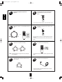
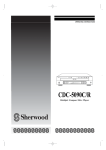
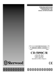
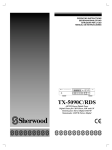
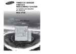
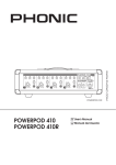
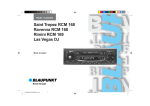
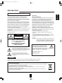
AX5103(G)2007.8.174:43PM페이지 1
Introduction
Congratulations on Your Purchase!
FOR U.S.A.
Your new high fidelity Amplifier is designed to deliver
maximum enjoyment and years of trouble free service.
Please take a few moments to read this manual thoroughly. It
will explain the features and operation of your unit and help
ensure a trouble free installation.
Please unpack your unit carefully. We recommend that you
save the carton and packing material. They will be helpful if
you ever need to move your unit and may be required if you
ever need to return it for service. Your unit is designed to be
placed in a horizontal position and it is important to allow at
least two inches of space behind your unit for adequate
ventilation and cabling convenience.
To avoid damage, never place the unit near radiators, in front
of heating vents, in direct sunlight, or in excessively humid or
dusty location.
Connect your complementary components as illustrated in
the following section.
�FCC INFORMATION
This equipment has been tested and found to comply with
the limits for a Class B digital device, pursuant to Part 15 of
the FCC Rules. These limits are designed to provide
reasonable protection against harmful interference in a
residential installation. This equipment generates, uses and
can radiate radio frequency energy and, if not installed and
used in accordance with the instructions, may cause harmful
interference to radio communications. However, there is no
guarantee that interference will not occur in a particular
installation. If this equipment does cause harmful
interference to radio or television reception, which can be
determined by turning the equipment off and on, the user is
encouraged to try to correct the interference by one or more
of the following measures :
• Reorient or relocate the receiving antenna.
• Increase the separation between the equipment and
receiver.
• Connect the equipment into an outlet on a circuit different
from that to which the receiver is connected.
• Consult the dealer or an experienced radio/TV technician
for help.
CAUTION
RISK OF ELECTRIC SHOCK
DO NOT OPEN
CAUTION : Any changes or modifications in construction of
this device which are not expressly approved by
the party responsible for compliance could void
the user’s authority to operate the equipment.
CAUTION : TO REDUCE THE RISK OF
ELECTRIC SHOCK, DO NOT REMOVE
COVER(OR BACK).
NO USER-SERVICEABLE PARTS INSIDE.
REFER SERVICING TO QUALIFIED
SERVICE PERSONNEL.
Caution regarding placement
(Except for U.S.A. and Canada)
To maintain proper ventilation, be sure to
leave a space around the unit (from the
largest outer dimensions including projections)
equal to, or greater than, shown below.
This symbol is intended to alert the user to the
presence of uninsulated "dangerous voltage" within the
product's enclosure that may be of sufficient magnitude
to constitute a risk of electric shock to persons.
Left and right panels : 5 cm
Rear panel : 10 cm
Top panel : 20 cm
This symbol is intended to alert the user to the
presence of important operating and maintenance
(servicing) instructions in the literature accompanying
the appliance.
WARNING
To reduce the risk of fire or electric shock, do not expose this appliance to rain or moisture.
Caution : Do not block ventilation openings or stack other equipment on the top.
NOTE ON RECYCLING
This product’s packaging materials are recyclable and can be reused. Please dispose of any materials
in accordance with the local recycling regulations.
When discarding the unit, comply with local rules or regulations.
Batteries should never be thrown away or incinerated but disposed of in accordance with the local
regulations concerning chemical waste.
This product and the accessories packed together constitute the applicable product according to the
WEEE directive except batteries.
2
ENGLISH
UNPACKING AND INSTALLATION
AX5103(G)2007.8.174:43PM페이지 2
ENGLISH
READ THIS BEFORE OPERATING YOUR UNIT
FOR U.S.A AND CANADA .............................. 120 V
FOR OTHER COUNTRIES .................. 110 V/ 220 V
FOR YOUR SAFETY
FOR YOUR SAFETY
Units shipped to the U.S.A and Canada are designed for
operation on 120 Volts AC only.
Units shipped to countries other than the above countries
are equipped with an AC voltage selector switch on the
rear panel. Refer to the following paragraph for the
proper setting of this switch.
Observe all safety precaution for use of a polarized AC
plug. However, some products may be supplied with a
non polarized plug.
AC VOLTAGE SELECTION
This unit operates on 110/220 V AC. The AC voltage
selector switch on the rear panel is set to the voltage that
prevails in the area to which the unit is shipped.
Before connecting the power cord to your AC outlet, make
sure that the setting position of this switch matches your
line voltage. If not, it must be set to your voltage in
accordance with the following direction.
CAUTION : To prevent electric shock, match wide blade
of plug to wide slot, insert fully.
FOR EUROPE AND AUSTRALIA ........ 230 V/240 V
AC voltage selector switch
FOR YOUR SAFETY
Units shipped to Australia are designed for operation on
240 V AC only.
To ensure safe operation, the three-pin plug supplied
must be inserted only into a standard three-pin power
point which is effectively earthed through the normal
household wiring. Extension cords used with the
equipment must be three-core and be correctly wired to
provide connection to earth.
Improper extension cords are a major cause of fatalities.
The fact that the equipment operates satisfactorily does
not imply that the power point is earthed and that the
installation is completely safe.
For your safety, if in any doubt about the effective
earthing of the power point, consult a qualified electrician.
AC 220 V
AC 110 V
Move switch lever to match your line voltage with a small
screwdriver or other pointed tool.
PAN-EUROPEAN UNIFIED VOLTAGE
All units are suitable for use on supplies 230-240 V AC.
3
AX5103(G)2007.8.174:43PM페이지 3
CONTENTS
• UNPACKING AND INSTALLATION
|
2
• READ THIS BEFORE OPERATING YOUR UNIT
System Connections
|
5
Front Panel Controls
|
7
|
DIGI LINK III System Remote Controls
|
8
• REMOTE CONTROL OPERATION RANGE
|
9
• LOADING BATTERIES
|
ENGLISH
Introduction
3
9
Operations
• LISTENING TO A PROGRAM SOURCE
• RECORDING
|
Troubleshooting Guide
Specifications
|
10
12
|
|
13
14
4
AX5103(G)2007.8.174:43PM페이지 4
ENGLISH
System Connections
• Do not connect the amplifier to the wall AC outlet when plugging and unplugging connection cords.
• Be sure to connect the white RCA pin cords to the L (left) and the red RCA pin cords to the R (right) jacks when making
connections.
• Make connections firmly and correctly. If not, it can cause loss of sound, noise or damage to the amplifier.
SN.
GND
MODEL NO.
AC INPUT
230V~50Hz
190W
AX-5103
INTEGRATED AMPLIFIER
SPEAKER A
ASSEMBLED IN CHINA
DESIGNED IN USA
PHONO
CD
TUNER
TAPE 1
/MD
TAPE 2
MONITOR
DIGI LINK
230V~50Hz
SWITCHED
100W(0.43A) MAX.
AC OUTLET
IN
OUT
IN
AVIS : RISQUE DE CHOC ELECTRIQUE-NE PAS OUVRIR.
WARNING : SHOCK HAZARD-DO NOT OPEN.
WARNING : TO REDUCE THE RISK OF FIRE OR ELECTRIC
SHOCK, DO NOT EXPOSE THIS APPLIANCE
TO RAIN OR MOISTURE.
OUT
SPEAKER B
�CONNECTING AUDIO
COMPONENTS
�CONNECTING SYSTEM
CONTROL
DIGI LINK
GND
PHONO
CD
TUNER
TAPE 1
/MD
TAPE 2
MONITOR
• Connect this jack to the DIGI LINK jack of the
external Sherwood component that uses the
DIGI LINK II or III remote control system.
• The TAPE1/MD IN/OUT jacks may also be connected to
the LINE OUT/IN jacks of an additional MD recorder.
• The TAPE2 MONITOR IN/OUT jacks may also be
connected to the LINE OUT/IN jacks of an optional graphic
equalizer.
5
AX5103(G)2007.8.174:43PM페이지 5
SN.
GND
MODEL NO.
AC INPUT
230V~50Hz
190W
Plug this cord into a wall AC outlet
AX-5103
INTEGRATED AMPLIFIER
SPEAKER A
ASSEMBLED IN CHINA
DESIGNED IN USA
PHONO
CD
TUNER
TAPE 1
/MD
TAPE 2
MONITOR
DIGI LINK
230V~50Hz
SWITCHED
100W(0.43A) MAX.
AC OUTLET
IN
OUT
IN
OUT
SPEAKER B
AVIS : RISQUE DE CHOC ELECTRIQUE-NE PAS OUVRIR.
WARNING : SHOCK HAZARD-DO NOT OPEN.
WARNING : TO REDUCE THE RISK OF FIRE OR ELECTRIC
SHOCK, DO NOT EXPOSE THIS APPLIANCE
TO RAIN OR MOISTURE.
�SWITCHED AC OUTLET
• This outlet is switched on (power on
mode) and off (standby mode)
according to power control as follows;
(Maximum total capacity is 100 W
(0.43A))
�CONNECTING SPEAKERS
Standby mode - switched AC outlet off
Power on mode - switched AC outlet on
• This amplifier enables you to listen to two pairs of speakers
individually or in various combinations.
Connect your main speakers to the SPEAKER A terminals and
use the SPEAKER B terminals for the remote pair located
elsewhere in your home.
• Never short circuit the + and - speaker cords.
• Be sure to connect speakers firmly and correctly according to the
channel (left and right) and the polarity (+ and -).
Note : For safe amplifier operation, use the speakers with
impedance of over 8Ω when you use either SPEAKER A or B
terminals and use the speakers with impedance of over 16Ω
when you use both SPEAKER A and B terminals.
6
ENGLISH
�AC INPUT CORD
AX5103(G)2007.8.174:43PM페이지 6
ENGLISH
Front Panel Controls
① POWER SWITCH
⑧ BALANCE CONTROL KNOB
Press this switch to enter the power off or the standby
mode.
Adjust the stereo balance between left and right
speakers.
• The center position is the normal condition.
② STANDBY INDICATOR
⑨ TONE DIRECT SWITCH
In the standby mode, this indicator lights up.
Press this switch to bypass the tone (bass and treble)
circuitry for pure sound.
③ SPEAKER SELECTOR A, B BUTTONS/
INDICATORS
⑩ LOUDNESS SWITCH
Press the button to switch the desired speakers on
or off.
Press this switch to emphasize the sound of frequencies
that are difficult to hear at low volume levels.
• The frequency emphasis varies according to the volume
level at which you are listening.
④ INPUT SELECTOR BUTTONS/INDICATORS
Press the button to select the desired input source.
• When the TAPE 2 MONITOR indicator lights up, other
inputs cannot be heard from the speakers.
To listen to a input source other than TAPE 2 MONITOR,
be sure to set the TAPE 2 MONITOR button to off.
⑪ HEADPHONE JACK
Stereo headphones with a standard 1/4 inch plug can be
plugged into this jack for private listening.
• When listening with headphones, turn off both
SPEAKER SELECTOR A and B buttons.
⑤ VOLUME CONTROL KNOB
Adjust the volume to a comfortable listening level.
⑫ REMOTE SENSOR
This receives the signals from the system remote control
unit.
⑥ BASS CONTROL KNOB
Adjust the low-frequency tone.
• The center position is the flat (normal) condition.
⑦ TREBLE CONTROL KNOB
Adjust the high-frequency tone.
• The center position is the flat (normal) condition.
7
AX5103(G)2007.8.174:43PM페이지 7
• You can remotely control not only this amplifier but also Sherwood compatible components bearing the DIGI LINK II or III logo.
• For system remote control operation, first make the DIGI LINK connections.
SPEAKER SELECTOR A, B
BUTTONS
INPUT SELECTOR BUTTONS
POWER BUTTON
In the standby mode, press this button
to enter the operating or the standby mode.
PRESET SCAN BUTTON
For scanning preset stations in sequence
in tuner mode.
NUMERIC BUTTONS
For selecting preset stations in tuner mode.
For selecting a track in CD mode.
MUTE BUTTON
Press this button to temporarily mute
the sound.
Press again to resume the previous
sound level.
SLEEP BUTTON
When the Sherwood components (including
tuner such as TX-5090C) are made
DIGI LINK III connections, the sleep timer of
Sherwood tuner allows the system to continue
operating for a specified period of time before
automatically shutting off.
Each time this button is pressed, the sleep
time on Sherwood tuner changes as follows;
DIMMER BUTTON
Each time this button is pressed,
the brightness of all fluorescent displays of
Sherwood components connected by
the DIGI LINK III changes together
as follows;
VOLUME UP/DOWN (+/-) BUTTONS
When the sleep time is selected, all display
panels of the system are dimly lit.
CD PLAYER SECTION
- to pause play.
- to stop play or to clear a program.
- to begin play.
TAPE DECK SECTION
DECK SELECTOR A, B - for selecting deck
A or B
,
- to begin reverse or forward side
playback.
- to stop playback or recording.
• In the DIGI LINK III remote control system, if pressing PLAY, etc. on CD player or tape deck, CD or TAPE 2 MONITOR is
selected automatically without selecting the input source and then PLAY, etc. starts.
Notes :
• Some functions for CD player or tape deck may not be available.
• For details about functions, refer to the operating instructions of each component.
8
ENGLISH
DIGI LINK III System Remote Controls
AX5103(G)2007.8.174:43PM페이지 8
ENGLISH
REMOTE CONTROL OPERATION RANGE
• Use the remote control unit within a range of about 7
meters (23 feet) and angles of up to 30 degrees aiming at
the remote sensor.
LOADING BATTERIES
1
Load two batteries matching the polarity.
Remove the cover.
2
2×1.5V
R 6/ SUM-3 / AA
• Remove the batteries when they are not used for a
long time.
• Do not use the rechargeable batteries (Ni-Cd type).
9
AX5103(G)2007.8.174:43PM페이지 9
Operations
Before operation
2
• Enter the standby mode.
Switch the desired speakers on.
or
• Then the corresponding SPEAKER indicator lights up
and the sound can be heard the speakers connected
to "SPEAKER A" or (and) "SPEAKER B" terminals.
• When using headphones for private listening, press
both SPEAKER SELECTOR A and B buttons to switch
the speakers off.
Note : For safe amplifier operation, be sure to check
impedance of the speakers connected. (Refer to
“CONNECTING SPEAKERS” on page 6)
• The STANDBY indicator lights up.
This means that the amplifier is not disconnected from
the AC mains and a small amount of current is
retained to support the memorized contents and
operation readiness.
• To switch the power off, push the POWER switch
again, then the power is cut off and the STANDBY
indicator goes off.
1
In the standby mode, turn the power on.
3
Select the desired input source.
or
• Each time the POWER button on the remote control
is pressed, the amplifier is turned on to enter the
operating mode or off to enter the standby mode.
• In the standby mode, if the INPUT SELECTOR
button is pressed, the amplifier is turned on
automatically and the desired input is selected.
• Then the corresponding indicator lights up.
• When the TAPE 2 MONITOR button is set to on so that
the TAPE 2 MONITOR indicator lights up, other inputs
can not be heard from the speakers.
To listen to a input source other than TAPE 2
MONITOR, be sure to set the TAPE 2 MONITOR
button to off.
�SYSTEM POWER ON/OFF
• If the POWER switch of Sherwood component
connected by the DIGI LINK II or III is kept pushed
and its AC input cord is plugged in the switched AC
outlet, each time the amplifier becomes the standby
or the operating mode, its power is turned off or on.
• Under the same conditions, if its AC input cord is not
plugged only in the switched AC outlet, when the
amplifier becomes the standby mode, only its display
is off (meaning that a small amount of current is
retained for operation readiness, etc.)
TAPE MONITOR function
You can connect either a tape deck or a graphic
equalizer to the amplifier’s TAPE 2 MONITOR jacks.
Only when you listen to the component connected to
these jacks, set the TAPE 2 MONITOR button to on.
If you connect a 3-head tape deck, you can listen to the
sound being recorded during recording, not the source
sound.
For further details, refer to the operating instructions of
the component connected.
10
ENGLISH
LISTENING TO A PROGRAM SOURCE
AX5103(G)2007.8.174:43PM페이지 10
8
To emphasize the sound of frequencies
that are difficult to hear at low volume
levels.
ENGLISH
4
Operate the selected component for
playback.
• To cancel the loudness effect, press this switch again.
5
Adjust the volume to a comfortable listening
level.
9
To listen to a program source without the
tone effect.
or
• You can listen to pure sound that bypasses the tone
circuitry.
• To cancel the tone direct function, press this switch
again.
6
Adjust the tone (bass and treble).
10
Note : Extreme settings at high volume may damage
your speakers.
7
To mute the sound temporarily.
• To resume the previous sound level, press this button
again.
Adjust the stereo balance between left and
right speakers.
11
To listen with the headphones
• Ensure that both SPEAKER SELECTOR A and B
buttons are set to off.
11
AX5103(G)2007.8.174:43PM페이지 11
RECORDING
Recording with TAPE 1/MD
1
Recording with TAPE 2 MONITOR
Select the desired input as recording
source except for TAPE 1/MD and TAPE 2
MONITOR.
1
Select the desired input as recording
source except for TAPE 2 MONITOR.
or
or
• Be sure that the TAPE 2 MONITOR indicator goes off.
2
Start recording on the tape deck or the MD
recorder connected to TAPE 1/MD.
2
Set the TAPE 2 MONITOR button to on.
or
3
Start play on the desired input.
3
4
Stat recording on the tape deck connected
to TAPE 2 MONITOR.
Start play on the desired input.
• When the TAPE 1/MD is selected as recording
sources, dubbing will start from TAPE 1/MD to TAPE 2
MONITOR.
• It is not possible to dub from TAPE 2 MONITOR to
TAPE 1/MD.
• For tape monitor function, refer to "TAPE MONITOR
function" on page 10.
12
ENGLISH
• The volume and tone (bass, treble) settings, etc. have no effect on the recording signals.
AX5103(G)2007.8.174:43PM페이지 12
ENGLISH
Troubleshooting Guide
If your unit should not perform as expected, consult the table below to see if the problem can be corrected
before seeking help from your dealer or our service organization.
PROBLEM
POSSIBLE CAUSE
REMEDY
No power
• The AC input cord is disconnected
• Poor connection at AC wall outlet or the outlet
is inactive.
• Connect the cord securely.
• Check the outlet using a lamp or
another appliance.
No sound
• Speaker cords are disconnected.
• Both SPEAKER SELECTOR A and B buttons
are set to off.
• The volume is adjusted too low.
• The MUTE button on the remote control is
pressed to ON.
• Incorrect selection of input source.
• Check the speaker connections.
• Switch the desired speakers on.
• Incorrect connections between the
components.
No recording
• Incorrect connections.
• Incorrect operation of the tape deck (or MD
recorder).
13
• Adjust the volume.
• Press the MUTE button to cancel the
muting effect.
• Select the desired input source
correctly.
• Make connections correctly.
• Make connections correctly.
• Operate the tape deck (or MD
recorder) correctly.
AX5103(G)2007.8.174:43PM페이지 13
Specifications
• Total harmonic distortion, 8 Ω, 100 W, 1 kHz
|
2 X 100 W
|
0.03 %
|
0.05 %
• Intermodulation distortion
60 Hz : 7 kHz = 4 : 1 SMPTE, 8 Ω, 100 W
• Input sensitivity, 47 kΩ
PHONO (MM)
|
3.0 mV
CD, TUNER, TAPE
|
200 mV
• Phono input overload, THD 0.5 %, 1 kHz
|
200 mV
PHONO (MM), RIAA, 40 Hz � 20 kHz
|
±1 dB
CD, TUNER, TAPE, 10 Hz � 60 kHz
|
+0 dB, -2 dB
• Signal to noise ratio, unweighted
PHONO (MM)
|
75 dB
CD, TUNER, TAPE
|
90 dB
• Frequency response
• Crosstalk, 1 kHz, 50 W
TAPE to CD
|
70 dB
CD to TAPE
|
70 dB
• Bass/Treble control, 100 Hz/10 kHz
|
±10 dB
• Loudness contour, 100 Hz/10 kHz
|
+6 dB / +3 dB
�GENERAL
• Power supply
|
230 V~50 Hz
• Power consumption
|
190 W
• AC outlet
Switched
|
TOTAL 100 W(0.43A) max.
• Dimensions (W X H X D)
• Weight (Net)
|
|
440 X 145 X 360 mm (17-3/8 X 5-3/4 X 14-1/8 inches)
8.75 kg (19.3 lbs)
Note : Design and specifications are subject to change without notice for improvements.
14
ENGLISH
• Power output, 8 Ω, THD 0.3 %, 40 Hz�20 kHz