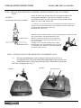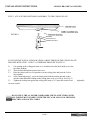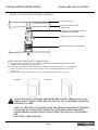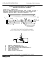
1
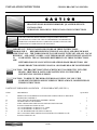
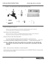
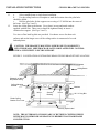
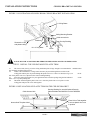
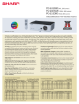
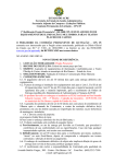
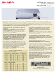
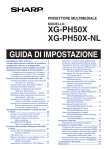
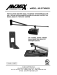
AN-PHCM20
INSTALLATION INSTRUCTIONS
FOR
MOUNTING BRACKET FOR USE
ONLY WITH SHARP PROJECTOR
MODEL XG-PH50X
CEILING MOUNTING
BRACKET AN-PHCM20
CEILING MOUNTING
BRACKET COMBINED
WITH OPTIONAL
ADJUSTABLE
EXTENSION TUBE
MODEL AN-EP101B
COPYRIGHT © 2005 SHARP ELECTRONICS CORPORATION
INSTALLATION INSTRUCTIONS
CEILING BRACKET AN-PHCM20
C A U T I O N
INSTALLATION OF THIS ADJUSTABLE CEILING MOUNTING
BRACKET SHOULD BE PERFORMED BY QUALIFIED SERVICE/
INSTALLATION
PERSONNEL FOLLOWING THE INSTALLATION INSTRUCTIONS
THE EXCLAMATION POINT WITHIN AN EQUILATERAL TRIANGLE
IS INTENDED TO ALERT THE USER TO THE PRESENCE OF IMPORTANT
OPERATING AND MAINTENANCE (SERVICING) INSTRUCTIONS IN THE
LITERATURE ACCOMPANYING THE APPLIANCE.
IMPORTANT! THE INSTALLER SHOULD READ THESE INSTRUCTIONS
THOROUGHLY
BEFORE BEGINNING THE INSTALLATION AND SHOULD MAKE
SURE THAT ALL THE WORK IS DONE IN COMPLIANCE WITH NEC AND ALL LOCAL
BUILDING AND SAFETY CODES. SAVE THIS BOOKLET AFTER THE INSTALLATION
IS
COMPLETED. THE ACCESSORIES REFERRED TO IN THESE INSTRUCTIONS
ARE
INTENDED FOR USE ONLY WITH COMPATIBLE SHARP PROJECTORS. SEE
SHARP PROJECTOR OWNER’S MANUAL OR SHARP DEALER TO DETERMINE
CAUTION: THE BRACKET MOUNTING SCREWS MUST GO DIRECTLY INTO THE
BEAMS. SHEETROCK, LATH AND PLASTER, WILL NOT PROVIDE A
SUFFICIENTLY SECURE SUPPORT.
CAUTION: TO REDUCE THE RISK OF PERSONAL INJURY, USE ONLY THE
COMPONENTS WHICH ARE INCLUDED IN THIS PACKAGE, OR SPECIFIED IN
THESE INSTRUCTIONS.
PARTS LIST FOR MODEL AN-PHCM20
CEILING BRACKET (SEE FIG. 1)
ITEM
DESCRIPTION
A.
PROJECTOR ATTACHMENT PLATE WHICH INCLUDES THE DUAL KNUCKLE
POSITIONING ASSEMBLY.
DUAL KNUCKLE POSITIONING ASSEMBLY DETAIL
LOCKING HEX NUT & WASHER
STEEL CEILING MOUNTING PLATE WITH SECURITY FITTING
PLASTIC TRIM FOR CEILING PLATE
1/4 X 10 HEX HEAD LAG BOLTS 2-1/2” LONG
1/4 X 10 HEX HEAD LAG BOLTS 3” LONG
1/4” I.D. WASHERS FOR USE WITH LAG BOLTS
M4 X 12mm MOUNTING SCREWS FOR USE WITH ATTACHMENT PLATE
PLASTIC TRIM COLLAR
B.
C.
D.
E.
F.
G.
H.
I.
J.
QUANTITY
PAGE 2
1
1
1
1
1
6
6
6
3
1
INSTALLATION INSTRUCTIONS
CEILING BRACKET AN-PHCM20
FIGURE 1. ILLUSTRATION OF PARTS FOR CEILING BRACKET
A.
D.
C.
B.
E.
F.
H.
I.
J.
G.
INVERT THE PROJECTOR IMAGE
Please refer to the owners manual for your LCD Projector for detailed instructions of how to electrically
invert the projected image to accommodate its use in the ceiling mounted mode.
LOCATION OF THE CEILING BRACKET
Please refer to the owner’s manual for your SHARP LCD PROJECTOR for information which will help you to
determine the best location for the placement of the ceiling mounting bracket assembly.
INSTALLATION OF THE CEILING BRACKET
After you have determined the appropriate location for the ceiling bracket, you must locate the exact
location of the ceiling beams. Most standard residential construction uses 16 inches between centers for overhead beams.
You can mount the ceiling bracket by straddling two beams, or you can install the
bracket in line with a single beam.
CAUTION: THE BRACKET MOUNTING SCREWS MUST GO DIRECTLY INTO THE BEAMS.
SHEETROCK, LATH AND PLASTER, WILL NOT PROVIDE A SUFFICIENTLY SECURE
SUPPORT.
STEP 1. INSTALLATION OF THE METAL CEILING BRACKET
After the location for the ceiling bracket has been determined, (see LCD PROJECTOR Owner’s Manual), make
sure to locate beams in the ceiling.
PAGE 3
INSTALLATION INSTRUCTIONS
1.1
1.2
CEILING BRACKET AN-PHCM20
a.
Select straddle beam or single beam installation.
b.
Use the ceiling bracket as a template to mark the location where the pilot holes
should be drilled.
c.
Drill the pilot holes for the support screws using a 1/8” drill bit into the center of
the beam. (See Figs. 2 and 3).
Screw the ceiling plate to the beams. Use at least 6 screws and metal washers
supplied with the unit. These screws should be tightened firmly to insure a
vibration-free support. (See Figs. 2 and 3).
Two sizes of hex head lag bolts are provided. Use shorter screws for sheet rock
surfaces and use the longer screws if the ceiling surface is constructed of a wood
lath and plaster.
CAUTION: THE BRACKET MOUNTING SCREWS MUST GO DIRECTLY
INTO THE BEAMS. SHEETROCK OR LATH AND PLASTER WILL NOT PROVIDE A SUFFICIENTLY SECURE SUPPORT.
FIGURE 2. ILLUSTRATION OF STRADDLE BEAM CEILING BRACKET INSTALLATION
Ceiling Beam
Sheetrock or lath
and plaster ceiling
Ceiling Mounting
Bracket
Washers
Velcro
Security
Bushing
Velcro
1/4 X 10 Lag Bolt
Plastic Ceiling
Bracket Trim Cover
Security Option Label
NOTE: THE OUTER ROW OF HOLES ARE 16” BETWEEN CENTERS WHICH
IS THE MOST COMMON BEAM SPACING IN RESIDENTIAL WOOD FRAME
CONSTRUCTION.
PAGE 4
INSTALLATION INSTRUCTIONS
CEILING BRACKET AN-PHCM20
FIGURE 3 ILLUSTRATION OF SINGLE BEAM CEILING BRACKET INSTALLATION
Ceiling Beam
Ceiling Mounting Bracket
Cable access hole
Washers
Security Bushing
Sheetrock or lath
and plaster ceiling
1/4 x 10 Lag Bolts
Velcro
DO NOT RUN THE AC POWER CORD THROUGH THE CEILING PLATE AND TRIM COVER
STEP 2. INSTALL THE CEILING MOUNT PLASTIC TRIM
2.1
The Access Hole (See Fig. 4) in the ceiling attachment plate is large enough to accommodate the molded connectors commonly used the with projector.
2.2
Audio, Video and other low voltage connections may be passed through the access hole in the
ceiling plate and may also be passed through the plastic trim cover. There is a label (See Fig. 4) on
the inside of the plastic trim cover, adjacent to the center mounting bushing.
2.3
Select the contour appropriate for your application and cut out the opening along the line indicated
on the
label. Use a very sharp cutting tool.
2.4
Thread the cable through the plastic trim cover. Place the plastic trim cover in place over the
ceiling plate and press the velcro tabs together.
FIGURE 4 INSTALLATION OF PLASTIC TRIM ON THE CEILING BRACKET
Security Bushing for use with Optional Security
Cable Kit Model AN-CMCSS16 or AN-CMCSS46
Cable Access Hole
Press Velcro Tabs together
to secure plastic trim cover
in position
Access Hole Template Label
PAGE 5
INSTALLATION INSTRUCTIONS
CEILING BRACKET AN-PHCM20
STEP 3 DETACH THE POSITIONING ASSEMBLY FROM THE PROJECTOR ATTACHMENT
PLATE.
FIGURE 5
POSITIONING KNUCKLE ASSEMBLY
NOTE: PLEASE LOOK OVER THE EXACT MANNER IN WHICH THE
POSITIONING ASSEMBLY AND THE ATTACHMENT PLATE GO
TOGETHER SO THAT YOU WILL BE ABLE TO REASSEMBLE THEM
WHEN YOU HANG THE PROJECTOR.
3.1 Using 9/16” box wrench, remove the nut and split lock washer from the lower
knuckle (vertical position) and slide the center and upper knuckle assembly apart
from the bottom knuckle which is part of the
attachment plate. (See Fig. 5)
REMOVE NUT
LOWER KNUCKLE
SPECIAL NOTE TO INSTALLERS: The positioning knuckle is mounted to provide
correct static balance when the standard lens is used.
When any of the other lens options are used the lens is
heavier and in order to improve the static balance, move
the 3 piece knuckle
assembly to one of the other mounting holes on the attachment plate. If the larger and heavier lens is selected,
use the furthest hole. All other mounting and adjustment
procedures remain the same.
STEP 4 INSTALLATION OF THE PROJECTOR ATTACHMENT PLATE
4.1
Place the attachment plate over the bottom of the projector (See Fig. 6)
and align the holes of the plate with the threaded fittings on the projector case.
4.2
Install the three M4 x 12mm long screws provided. Fasten these securely but
DO NOT overtighten. (See Fig. 7)
FIGURE 6.
FIGURE 7.
PAGE 6
M4x12mm screws
INSTALLATION INSTRUCTIONS
CEILING BRACKET AN-PHCM20
STEP 5 ATTACH THE POSITIONING ASSEMBLY TO THE CEILING PLATE
FIGURE 8
WASHER
LOCKING NUT
UPPER KNUCKLE
IF YOU INTEND TO RUN AUDIO OR VIDEO CABLES THROUGH THE CEILING PLATE
PROCEED WITH STEP 5.1 AND 5.2, OTHERWISE PROCEED TO STEP 5.3:
5.1
Cut opening in the ceiling plate trim cover as indicated on the label inside cover near
the center bushing.
5.2
Thread cables through the plastic trim cover.
5.3
Place the plastic trim cover in position over the ceiling plate and press the Velcro
tabs together.
5.4
After completing step #3, screw the longer shaft with the locking nut and washer
into the center threaded bushing on the ceiling plate as far as it will go. (See Fig. 8)
5.5
Tighten the locking nut against the ceiling plate using a 3/4” open end wrench or an
crescent wrench.
DO NOT RUN THE AC POWER CORD INSIDE THE PLASTIC TRIM COVER.
ALL WIRING MUST COMPLY WITH THE NEC AND ALL LOCAL BUILDING,
ELECTRIC, AND SAFETY CODES.
PAGE 7
adjustable
INSTALLATION INSTRUCTIONS
CEILING BRACKET AN-PHCM20
STEP 6 HANGING THE PROJECTOR FROM POSITIONING ASSEMBLY
IT IS RECOMMENDED THAT TWO PERSONS SUPPORT THE PROJECTOR
WHEN RAISING IT UP IN ORDER TO HANG IT IN PLACE.
6.1
Raise the projector with the mounting plate attached and slide the fitting (See Fig. 9)
over the support stud on the hanging position.
6.2
Replace the locking nut and split lock washer (removed in step 3.1). Using the 9/16”
run the nut up but do not tighten all the way.
box wrench
FIGURE 9
STEP 7 AIM THE PROJECTOR
CAUTION: DO NOT OVER-TIGHTEN THE POSITIONING NUTS. When doing image
positioning alignment, tighten the nuts until the split ring washer flattens out and then only just enough additional tightening to hold the set position.
7.1
After the projector has been property wired, turn it on and loosen the positioning
assembly adjustment nuts just enough so that you can move the projector fairly easily.
(See Fig.
10) DO NOT COMPLETELY LOOSEN THE NUTS.
7.2
Set the Horizontal Centering by loosening the ceiling locking nut, move the projector to center the
image and tighten the nut. (Use 3/4” open end wrench).
7.3
Set the vertical centering and secure the lower positioning adjustment nut.
(See Fig. 10)
7.4
Set the Horizontal tilt and secure the upper positioning adjustment nut. (See Fig. 10)
SECURITY:
The ceiling plate and the projector attachment plate of this
model mounting bracket kit are equipped with
attachment facilities that enable the use of a SHARP Model
AN-CMCSS16 or AN-CMCSS46 theft
prevention security cable optional accessory.
PAGE 8
Threaded hole lines up with
center hole in lock base.
Anti-spin hole aligns with
anti-spin pin on lock base.
INSTALLATION INSTRUCTIONS
CEILING BRACKET AN-PHCM20
FIGURE 11 DETAIL OF POSITIONING ASSEMBLY
CEILING PLATE
PLASTIC CEILING PLATE
TRIM COVER
LOCKING NUT AND HORIZONTAL
POSITION ADJUSTMENT
HORIZONTAL TILT ADJUSTMENT
VERTICAL POSITION ADJUSTMENT
STEP 8 INSTALL THE PLASTIC TRIM COLLAR
8.1 The plastic trim collar may be used as a cosmetic concealment of the positioning adjustment knuckle
assembly and the audio and video signal cables.
8.2 The slit side of the collar enables the installer to spread the collar enough to place it over the adjustment
knuckle. It will curve back by its own spring action to wrap around itself enough to close the gap.
(See Fig. 12)
8.3 If the projector is hung at a sharp angle, you may trim the collar for a better fit. (See Fig. 13)
FIGURE 12
FIGURE 13
DO NOT RUN THE AC POWER CORD INSIDE THE PLASTIC TRIM COLLAR. ALL
WIRING MUST COMPLY WITH THE NEC AND ALL LOCAL BUILDING, ELECTRIC
AND SAFETY CODES.
NOTE: IN THE EVENT YOU WISH TO USE THE SHARP ADJUSTABLE EXTENSION
ACCESSORY IN CONJUNCTION WITH THE CEILING MOUNTING BRACKET,
PLEASE REFER TO THE INSTALLATION INSTRUCTION MANUAL INCLUDED IN
THE
EXTENSION TUBE PACKAGE.
PAGE 9
INSTALLATION INSTRUCTIONS
CEILING BRACKET AN-PHCM20
DIMENSIONS AND MEASUREMENTS OF COMPONENTS FOR
SHARP MOUNTING BRACKET AN-MBCM10
CEILING PLATE 4” WIDE X 18” LONG
DISTANCE BETWEEN SETS OF MOUNTING HOLES: 1st SET 12”, 2nd SET 14”, 3rd SET 16”
ADDITIONAL POSSIBLE COMBINATIONS OF MOUNTING HOLE DISTANCE 13” & 15”
THREAD SIZE OF SWIVEL SHAFT & CEILING PLATE BUSHING 1/2” X 20
15
”
VELCRO
4”
VELCRO
12”
14”
16”
18”
SECURITY ANCHOR FITTING
CENTER BUSHING 7/8” DEEP
1/2X20 THREADED HOLE
CABLE ACCESS HOLE
ATTACHMENT PLATE WITH POSITIONING ASSEMBLY:
SPECIFICATIONS SUBJECT TO CHANGE WITHOUT NOTICE
1 7/8”
7 1/4”
6 1/4”
A.
B.
C.
D.
E.
F.
From ceiling to bottom of projector 13 5/8”
Length of position adjustment knuckle assembly 3 5/8”
Lens offset from center of lens to center of mounting bushing 1 5/8”
Ceiling to center of lens 10 1/16”
Ceiling to top of projector 6 1/2”
Mounting screws M4 X 12mm long metric.
SPECIFICATIONS SUBJECT TO CHANGE WITHOUT NOTICE
PAGE 10
INSTALLATION INSTRUCTIONS
CEILING BRACKET AN-PHCM20
ONE YEAR LIMITED WARRANTY
SHARP Electronics Corporation warrants to the first end use purchaser, that this SHARP brand
product (the “Product”), when shipped in its original container, will be free from defective
workmanship and materials, and agrees that it will, at its option, either repair the defect or replace
the defective product or part thereof at no charge to the purchaser for parts or for labor, excluding
costs of removal and/or installation, for one year from date of purchase.
This warranty does not apply to any appearance items of the Product nor to any Product the
exterior of which has been damaged or defaced, which has been subject to misuse, abnormal
service or handling, or which has been altered or modified in design or construction.
In order to avail the purchaser of his/her rights under this limited warranty, the purchaser should
carry in or ship the Product prepaid and insured, including proof of purchase, to:
SHARP Electronics, c/o AVDEX, 115 Henry Street, Freeport, NY 11520.
The limited warranty described above is in addition to whatever implied warranties may be
granted to purchasers by law. To the extent permitted by applicable law ALL IMPLIED
WARRANTIES INCLUDING THE WARRANTIES OF MERCHANTABILITY AND FITNESS FOR
USE ARE LIMITED TO THE PERIOD(S) FROM THE DATE OF PURCHASE SET FORTH
ABOVE. Some states do not allow limitations on how long an implied warranty lasts, so the
above limitation may not apply to you.
Neither the sales personnel of the seller nor any other person is authorized to make any
warranties other than those described above, or to extend the duration of any warranties beyond
the time period described above on behalf of SHARP.
The warranties described above shall be the sole and exclusive warranties granted by SHARP
and shall be the sole and exclusive remedy available to the purchaser. Correction of defects, in
the manner and for the period of time described herein, shall constitute fulfillment of all liabilities
and responsibilities of SHARP to the purchaser with respect to the Product, and shall constitute
full satisfaction of all claims, whether based on contract, negligence, strict liability or otherwise.
In no event shall SHARP be liable, or in any way responsible, for any damages or defects in the
Product which were caused by repairs or attempted repairs performed by anyone other than
SHARP. Nor shall SHARP be liable or in any way responsible for incidental or consequential
economic or property damage. Some states do not allow the exclusion of incidental or
consequential damages, so the above exclusion may not apply to you.
THE WARRANTY GIVES YOU SPECIFIC LEGAL RIGHTS. YOU MAY ALSO HAVE OTHER
RIGHTS WHICH VARY FROM STATE TO STATE.
Specifications are subject to change without notice.
SHARP ELECTRONICS CORPORATION, SHARP PLAZA, MAHWAH, NJ 07430
PAGE 11
COPYRIGHT © 2005 SHARP ELECTRONICS CORPORATION
AN-PHCM20
SUPPLEMENTAL INSTRUCTIONS
FOR INSTALLATION OF 2” EXTENSIONS TO
LOWER MOUNTING BRACKET FROM CEILING.
CEILING PLATE
COVER
INSTALL
ONE 2” EXTENSION OR
TWO 2” EXTENSIONS
HERE AS NEEDED.
CONTINUE WITH STEP 5
OF THE INSTALLATION
INSTRUCTIONS.
COPYRIGHT © 2005 SHARP ELECTRONICS CORPORATION