1
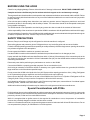
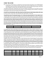
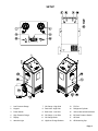
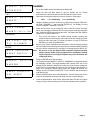
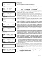
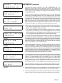
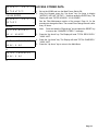
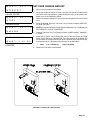
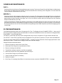
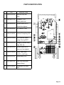
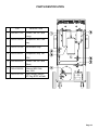
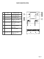
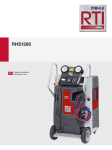
OPERATION
&
MAINTENANCE
MANUAL
AC880
Refrigerant Handling System
Manual P/N 035-80749-00
TABLE OF CONTENTS
AC880
Before Using the AC880 . . . . . . . . . . . . . . . . . . . . . 2
Safety Precautions . . . . . . . . . . . . . . . . . . . . . . . . . . 2
Using the AC880 . . . . . . . . . . . . . . . . . . . . . . . . . . . 3
Setup . . . . . . . . . . . . . . . . . . . . . . . . . . . . . . . . . . . . 4
Fill Charge Cylinder . . . . . . . . . . . . . . . . . . . . . . . . . 5
Recover/Recycle . . . . . . . . . . . . . . . . . . . . . . . . . . . 6
Drain Recovered Oil . . . . . . . . . . . . . . . . . . . . . . . . . 7
Deep Vacuum . . . . . . . . . . . . . . . . . . . . . . . . . . . . . 8
Charge . . . . . . . . . . . . . . . . . . . . . . . . . . . . . . . . . . . 9
Automatic . . . . . . . . . . . . . . . . . . . . . . . . . . . . . . . . . 10
Access Stored Data . . . . . . . . . . . . . . . . . . . . . . . . . 12
Set Over Charge Amount . . . . . . . . . . . . . . . . . . . . . 13
Scheduled Maintenance . . . . . . . . . . . . . . . . . . . . . 14
Filter Maintenance . . . . . . . . . . . . . . . . . . . . . . . . . . 14
Parts Identification . . . . . . . . . . . . . . . . . . . . . . . . . . 15
Troubleshooting Fill Cylinder Procedure . . . . . . . . . 18
CONGRATULATIONS
You have purchased one of the finest Recovery, Recycling,
and Charging Machines available!
Your AC880 was proudly manufactured for MATCO Tools by
RTI Technologies Inc., York, PA.
Fill out and return the Warranty Card within 90 days to
activate the warranty and free lifetime technical support.
TECHNICAL SUPPORT
800-468-2321 (Ext. 259)
[email protected]
BEFORE USING THE AC880
Check for any shipping damage. Place a claim with carrier if damage is discovered. DO NOT USE A DAMAGED UNIT.
Complete and return the Warranty Card to activate technical support service and warranty coverage.
These general instructions describe normal operation and maintenance situations encountered with the AC880. Failure
to read and comply with these instructions or any one of the limitations noted herein can result in serious injury and/or
property damage.
A few minutes spent reading these instructions can make an operator aware of dangerous practices to avoid and
precautions to take for his own safety and the safety of others. The instructions should not be interpreted to anticipate
every possible contingency.
The AC880 should not be operated or serviced by any person who has not read all the contents of this manual.
It is the responsibility of the owner/user to operate the AC880 in accordance with all specifications and laws which apply.
A regular schedule of inspection of the AC880 should be established and records maintained with special attention given
to Hoses, Compressor Oil Level, Vacuum Pump Oil Level, and Filters.
SAFETY PRECAUTIONS
Recover, Recycle, and Charge only the refrigerant for which the machine is configured.
Wear safety glasses and protective gloves. Refrigerant has a very low boiling point and can cause frostbite.
Follow the AC880 operating procedures sequentially to avoid prematurely disconnecting hoses or opening valves which
may release refrigerant to the atmosphere.
Do not expose the AC880 to moisture or operate in wet areas.
Use the AC880 in locations with mechanical ventilation that provides at least four air changes per hour.
Hoses used with the AC880 must have shutoff devices within 12 inches (30 centimeters) of the connection point to the
A/C System to minimize the introduction of Non-Condensable Gas (Air) into the AC880 and the release of refrigerant
when being disconnected.
Disconnect power before performing any maintenance or service on the AC880.
Connect the AC880 to a properly grounded receptacle. Do not overload the circuit.
Avoid using an extension cord with the AC880. If necessary use a good condition three wire, grounded, #14 AWG or
larger extension cord of the shortest possible length.
Do not connect the AC880 to the liquid side of any A/C System with a capacity greater than 4 lbs (1.8 Kg). Refrigerant
in A/C Systems having larger capacities must be recovered from the vapor side only.
Never connect the Red or Blue Hose on the rear of the AC880 to the Liquid Port of a Cylinder of Refrigerant to fill the
Charge Cylinder. Doing so may cause the Compressor to fail and void the warranty.
Avoid breathing refrigerant or lubricant vapor or mist. Exposure may irritate eyes, nose and throat. If accidental system
discharge occurs, ventilate work area before continuing.
Additional health and safety information may be obtained from refrigerant and lubricant manufacturers.
Special Considerations with R134a
R134a has been shown to be nonflammable at ambient temperature and atmospheric pressure. However, tests under
controlled conditions have indicated that at pressures above atmospheric and with air concentrations greater than 60
percent by volume, R134a can form combustible mixtures.
While it is recognized that an ignition source is also required for combustion to occur, the presence of combustible
mixtures is a potentially dangerous situation and should be avoided.
Under no circumstances should any equipment be pressure tested or leak tested with Air and R134a mixtures. Do not
use compressed air (shop air) for leak detection in R134a systems.
Page 2
USING THE AC880
Note: The purpose of this discussion is to familiarize the user with the features and functions of the AC880 Refrigerant
Handling Station. The procedures discussed in this manual assume that the AC880 has been set up in accordance
with the figures which are referred to and that the AC880 has been connected to the proper power supply. This manual
does not illustrate correct A/C service, but rather how to correctly use the AC880.
The AC880 is microprocessor controlled with a menu driven user interface. All of the functions of the AC880 are accessed
by pressing a few simple key strokes and following the prompts. The internal Charging Cylinder is attached to a strain gauge
measuring device (load cell) and the weight is electronically displayed.
The AC880 has a Fill Cylinder feature that allows refrigerant to be loaded directly into the Charging Cylinder without going
through the normal Recover/Recycle mode. When selected, this feature allows the AC880 Charging Cylinder to be re-filled
in just a few minutes, at which point it will automatically stop at approximately 13 lbs (6 Kg).
The AC880 Recovers and Recycles simultaneously in a true “single pass” through the filters and stores the refrigerant in the
Charging Cylinder where it is immediately available for use. This process automatically stops at 17.5 lbs (8 Kg) or when a
15 In Hg (-0.5 Bar) vacuum is sensed. The AC880 will wait for a minimum factory default of two minutes for “out gassing”
of cold refrigerant to raise the pressure back up to 3 psig (0.2 Bar) which would cause the Recover/Recycle process to start
again and reset this two minute Recycle Hold Timer before displaying that the process is complete. The Recycle Hold Timer
can be changed every time a Recover/Recycle procedure is run. Longer times should be selected on colder days or for A/C
Systems with large liquid capacities. Increasing this value may increase total time to Recover/Recycle while decreasing the
time may result in an incomplete Recovery of the A/C System. Refer to the chart below for guidelines on setting the Recycle
Hold Timer. The value entered is stored in the memory of the AC880 and becomes the default value each time it is set. NonCondensable Gases are vented automatically during Recovery/Recycle. The Amount of refrigerant recycled is displayed at
the end of the procedure. This value is added to the Total Amount Recycled and stored in the memory of the AC880 (See
Access Stored Data on Page 12).
Temperature
Recycle Hold Time
Less than 500F (100C)
10 minutes
500F (100C) to 800F (26.50C)
5 minutes
Greater than 800F (26.50C)
2 minutes
An integrated Deep Vacuum Pump draws on both the High and Low Hoses, ensuring complete evacuation of the A/C
System. The amount of time that the Vacuum Pump has been programmed to run will count down on the display. The value
entered is stored in the memory of the AC880 and becomes the default value each time it is set. The Low Pressure Gauge
can be used to monitor a rise in A/C System pressure. When programmed to do so, the AC880 will pause and start a count
up timer indicating how long the Vacuum Pump has been off, thus allowing the operator to determine if a vacuum leak is
present based on increasing pressure over time. A rapid rise in pressure indicates the presence of a large leak that should
be repaired. A slow rise in pressure may simply indicate that a longer Recycle Hold Time or Vacuum Time value should have
been entered. A relatively constant vacuum reading over a long period of time (less than 2 InHg rise over ten minutes) is the
most accurate way to check for vacuum leaks. The AC880 can also be programmed to pause to allow oil to be added to the
A/C System after vacuuming and prior to charging.
Charging is done from the internal Charging Cylinder. The A/C Capacity is entered using the Keypad. The value entered is
stored in the memory of the AC880 and becomes the default value each time it is set. The AC880 can dispense liquid
refrigerant through either the High or Low Side Hose by changing the position of a selector switch. As refrigerant leaves the
AC880, the display will show an increasing weight to the programmed charge amount plus a factory set one ounce (0.03 Kg)
Over Charge Amount necessary for compensation of refrigerant loss in the hoses. This Over Charge Amount can be changed
to accommodate different operating conditions (see Set Over Charge Amount on Page 13.) An integrated heater
automatically engages whenever Charging occurs. The amount of refrigerant charged is added to the total amount charged
and stored in the memory of the AC880 (see Access Stored Data on Page 12).
The AC880 can be programmed to perform the Recover/Recycle, Deep Vacuum and Charge in a completely Automatic
mode. The AC880 will always go through the Recover/Recycle procedure, but will go immediately to the Recycle Hold Timer
if the A/C System is empty. The following matrix outlines the most commonly used options that can be programmed:
Recover/Recycle
Deep Vacuum
Vacuum Leak Check
Add Oil
Charge
X
X
X
X
X
X
X
X
X
X
X
X
X
X
X
X
X
X
X
X
X
X
X
X
Page 3
SETUP
1
Low Pressure Gauge
7
Oil Charge - High Side
13
Fill Port
2
Keypad
8
Red Hose - High Side
14
Refrigerant Cylinder
3
Power Switch
9
Blue Hose - Low Side
15
Yellow Hose w/Anti-blowback
4
High Pressure Gauge
10
Oil Charge - Low Side
16
Oil Drain Pressure Switch
5
Display
11
Oil Charge Bottle
17
Oil Drain
6
Attention Light
12
High/Low Charge Selector
18
Oil Measuring Cup
Page 4
WEIGHT=
L B FILL CHARGE CYLINDER
XX.X
AUTOMATIC?
#
>>>>
WEIGHT=
FILL
XX.X
LB
CYLINDER?
#
N N N EXTREMELY IMPORTANT N N N
Always connect Yellow Hose (15) to Cylinder (14) first and then connect
other end of hose with anti-blowback valve to Fill Port (13) on AC880.
Note:
ENTER
CHECK
HOSES
START?
#
ENTER
XX.X
COMPRESSOR
FILL
LB
ON
XX.X
LB#
3. Open the LIQUID Valve on the Refrigerant Cylinder (14) connected to the Fill
Port (13) with the Yellow Hose (15).
4. Press the ENTER key when ready to start filling the AC880.
ENTER
The Display will read “WEIGHT=XX.X LB” “COMPRESSOR ON”. When the
level is approximately 13 lbs (6 kg), 75 percent of the full capacity, the AC880
will turn OFF, the Display will read “FILL COMPLETE” “FILLED= XX.X LB #”
(the amount of refrigerant removed from the cylinder) and the Attention Light
will turn ON. Close the Liquid Valve on the Refrigerant Cylinder.
*
HIGH
PRESSURE
MANUAL
Note: Press the RESET button on the Keypad to stop the
Fill Cylinder procedure at any time.
**
CYLINDER
GO
The AC880 uses 15.4 lbs (7 Kg) of refrigerant when Filling the first
time. If the Refrigerant Cylinder (14) is emptied, the AC880 will
appear to stop filling (the Weight will stop rising) and will stay in
this condition until the RESET key is pressed.
2. Using the Keypad, press the “Up Arrow” key four times to display “WEIGHT=
XX.X LB” “FILL CYLINDER? #” and press the ENTER key. The Display will
read “CHECK HOSES” “START? #”.
COMPLETE
FILLED=
SEE
1. Set up the AC880 as shown on Page 4 and then turn the Main Power Switch
ON. An adapter is provided with the AC880 (R134a) which permits the Yellow
Hose (15) to be attached to the 1/4 SAE Flare fitting that is on some cylinders
of R134a refrigerant.
Note:
WEIGHT=
For large capacity or multiple A/C Systems where recharge will NOT
be done between successive recoveries, it may be desirable to skip
this procedure.
TO
FULL
CHARGE
#
5. Press the ENTER key to return to the Main Menu.
*
While filling the Charging Cylinder, this screen will display periodically
concurrent with the Attention Light turning ON. This is normal and
nothing to be concerned about. The screen should revert to normal after
a few seconds.
**
This screen will display when the Charging Cylinder fills to capacity,
approximately 17.5 lbs (8 Kg). If this occurs, the weight can be lowered
using the Charge procedure on Page 9 before the AC880 can be used
to recover more refrigerant. Press the ENTER key to return to the Main
Menu.
PROBLEMS ?
Refer to Page 18 should
problems be encountered using
the Fill Cylinder procedure.
Pressure differential between
the cylinder of new refrigerant
and the internal AC880 charge
cylinder greatly affect the
efficiency and speed of the Fill
Charge Cylinder procedure.
Note:
The AC880 Charging Cylinder can also be filled from the GAS or
VAPOR side of a cylinder by following the Recover/Recycle
procedure on Page 6.
Note:
The AC880 will use 1.1 lb (0.5 Kg) more refrigerant than the
displayed value the very first time it is used or after performing
a Calibration Procedure in order to prime the internal
components.
Note:
The Yellow Hose (15) can be removed from the Fill Port (13) and
connected to either the Blue or Red Hose connection port on the
rear of the AC880 to recover the refrigerant left in the Yellow
Hose (15) using the Recover/Recycle procedure on Page 6.
Page 5
WEIGHT=
L B RECOVER/RECYCLE
XX.X
AUTOMATIC?
#
>
WEIGHT=
XX.X
LB
RECYCLE?
1.
Set up the AC880 and turn the Main Power Switch ON.
2.
Attach the Red and Blue Hoses to the A/C System per the vehicle
manufacturer's instructions, open the Red and Blue Hose Valves.
3.
Using the Keypad, press the “Up Arrow” key one time to display “WEIGHT=
XX.X LB” “RECYCLE? #” and press the ENTER key. The Display will read
“RECYCLE HOLD” “TIME XX MIN #”.
#
The Recycle Hold Time is the amount of time that the AC880 waits for “outgassing” or for the pressure in the A/C System to rise enough to automatically
restart the recovery process. The minimum value is two minutes. The value
entered is stored in memory and displays as the default value the next time the
procedure is used.
ENTER
RECYCLE
HOLD
TIME
MIN
XX
#
>< ENTER
CHECK
HOSES
START?
4.
Press the “Up Arrow” key to change the value of the field. Press the “Right
Arrow” key to change to a different field. Press the ENTER key to accept the
value. The Display will then read “CHECK HOSES” “START? #”.
5.
Press the ENTER key to start recovering and recycling with the AC880.
#
The Display will read the “WEIGHT= XX.X LB” “COMPRESSOR ON”. The
AC880 will recover and recycle refrigerant from the A/C System and
automatically cycle OFF when a vacuum is sensed. This vacuum level can be
seen on the Low Pressure Gauge. The Display will read “WEIGHT= XX.X LB”
“COMPRESSOR OFF”
ENTER
WEIGHT=
XX.X
COMPRESSOR
WEIGHT=
LB
OFF
RECYCLED=
XX.X
LB#
ENTER
DRAIN
OIL
#
ENTER
*
SEE
6.
Close the Red and Blue Hose Valves and disconnect the hoses from the A/C
System.
7.
Press the ENTER key. The Display will read “DRAIN RECOVERED OIL NOW!”.
Drain any recovered oil using the Drain Recovered Oil procedure on Page 7.
8.
Press the ENTER key to return to the Main Menu.
*
RECOVERED
NOW!
HIGH
A small quantity of refrigerant will probably remain in the A/C System as
observed by an increasing pressure on the Low Pressure Gauge. The AC880
will automatically cycle ON to continue recovering refrigerant if pressure rises
to a preset level. This automatic cycling will repeat, resetting the Recycle Hold
Timer each time. When the AC880 remains OFF for the duration of the Recycle
Hold Timer value entered in Step 4 the Display will read “AMOUNT
RECYCLED=” “XX.X LB #” from the A/C System and the Attention Light will turn
ON.
ON
XX.X
COMPRESSOR
AMOUNT
LB
This screen will display if there is an internal fault. Turn the AC880 Main
Power Switch OFF. Contact RTI Technical Support.
** This screen will display when the Charging Cylinder fills to capacity,
approximately 17.5 lbs (8 Kg.) If this occurs, the Weight can be lowered
using the Charge procedure on Page 9 before the AC880 can be used to
recover more refrigerant. Press the ENTER key to return to the Main Menu.
PRESSURE
MANUAL
**
CYLINDER
GO
TO
FULL
CHARGE
#
Page 6
DRAIN RECOVERED OIL
Oil is separated from the recovered refrigerant and MUST be removed following
EACH Recover/Recycle procedure to determine the amount (if any) necessary to
add into the A/C System as follows:
Note:
The AC880 must be connected to power source. Drain Recovered Oil
may be done while the AC880 Vacuum Pump is ON.
1.
Press and hold the Oil Drain Re-pressurization Switch (16) for 5 seconds and
then release it.
2.
Slowly open the Oil Drain Valve (17) to drain any oil which may have been
removed from the A/C System.
Unless the A/C System had previously been overfilled, the AC880 will typically
not remove enough oil to make replenishment necessary.
3.
Close the Oil Drain Valve (17).
4.
Press and hold the Oil Drain Re-pressurization Switch (16) for 5 seconds. This
permits any residual Non-Condensable Gas to be re-circulated for reprocessing
during the next recycle procedure.
Page 7
WEIGHT=
XX.X
L B DEEP VACUUM
#
AUTOMATIC?
>>
WEIGHT=
XX.X
LB
1.
Set up the AC880 and turn the Main Power Switch ON.
2.
Attach the Red and Blue Hoses to the A/C System per the vehicle
manufacturer's instructions and open the Red and Blue Hose Valves.
3.
Using the Keypad, press the “Up Arrow” key two times to display “WEIGHT=
XX.X LB” “VACUUM? #” and press the ENTER key. The Display will read
“ENTER VACUUM” “TIME XX MIN #”.
#
VACUUM?
* This screen will display if the AC880 senses a pressure in either the High or Low
ENTER
*
A/C
GO
HAS
TO
Pressure Hoses. When this occurs, the A/C System must be emptied using the
Recover/Recycle procedure on Page 6. Press the ENTER key to return to the
Main Menu.
PRESSURE
RECYCLE
#
4.
Press the “Up Arrow” key to change the value of the field. Press the “Right
Arrow” key to change to a different field. The value entered must be greater than
zero. Press the ENTER key to accept the value. The Display will read
“PERFORM LEAK” “TEST? Y/N#”.
5.
Press the “Right Arrow” key to move the cursor between Y and N to select
whether or not the AC880 pauses at the end of Vacuuming so that a vacuum
leak can be detected in the A/C System. Press the ENTER key to accept the
Yes or No choice. The choice entered is stored in memory and comes up as the
default the next time the procedure is used. The Display will read “ADD OIL?
Y/N#”.
6.
Press the “Right Arrow” key to move the cursor between Y and N to select
whether or not the AC880 pauses at the end of Vacuuming (or Vacuum Leak
Checking) to allow the Adding of Oil to the A/C System. Press the ENTER key
to accept the Yes or No choice. The choice entered is stored in memory and
comes up as the default the next time the procedure is used. The Display will
read “START? #”.
7.
Press the ENTER key to start the Vacuum Pump.
ENTER
ENTER
TIME
VACUUM
XX
MIN
#
>< ENTER
PEFORM
LEAK
Y/N#
TEST?
< ENTER
ADD
Y/N#
OIL?
The Vacuum Pump will turn On, the Display will read “TIME LEFT=XX MIN”
“PUMP ON” and the minutes remaining will count down on the Display. The
Vacuum Pump will turn OFF when the Display reads zero minutes.
< ENTER
8.
If a Vacuum Leak Check was selected by choosing Y in Step 5 the Display will
read “PUMP OFF XX MIN” “CONTINUE? #” and the Attention Light will turn ON.
The elapsed time since the Vacuum Pump turned OFF will count up on the
Display. An increasing pressure on the Low Pressure Gauge is evidence of a
vacuum leak in the A/C System. Press the ENTER key to return to the Main
Menu or to Add Oil if selected in Step 6.
9.
If Add Oil was selected by choosing Y in Step 6 the Display will read “ADD OIL
NOW” “CONTINUE? #”, and the Attention Light will turn ON. Refer to Figure 4
and connect Oil Charge Bottle (11) to Oil Charge High Side (7) or Oil Charge
Low Side (10) based on the vehicle manufacturer’s instructions for charging high
or low side. Open the valve on the Oil Charge Bottle (11), and leaving it open
until the correct amount of oil has left the Oil Charge Bottle. Close the valve on
the Oil Charge Bottle and press the ENTER key to return to the Main Menu.
#
START?
ENTER
TIME
LEFT=XX
PUMP
ON
PUMP
OFF
XX
CONTINUE?
MIN
MIN
#
ENTER
ADD
OIL
NOW
CONTINUE?
#
ENTER
Page 8
WEIGHT=
L B CHARGE
XX.X
#
AUTOMATIC?
>>>
WEIGHT=
XX.X
LB
#
CHARGE?
1.
Set up the AC880 and turn the Main Power Switch ON.
2.
Attach the Red and Blue Hoses to the A/C System per the vehicle
manufacturer's instructions and open the Red and Blue Hose Valves.
3.
Determine the refrigerant capacity of the A/C System to be charged.
Note:
CHARGE
AMOUNT=
XX.X
Using the Keypad, press the “Up Arrow” key three times to display “WEIGHT=
XX.X LB” “CHARGE? #” and press the ENTER key. The Display will read
“ENTER CHARGE” “AMOUNT= XX.X LB #”.
5.
Press the “Up Arrow” key to change the value of the field. Press the “Right
Arrow” key to change to a different field. The value entered must be greater than
zero. Press the ENTER key to accept the value. The Display will read “CHECK
HIGH-LOW” “CHARGE SWITCH #”.
LB#
>< ENTER
*
*
LOW
LEVEL ,
FILL
GO
TO
CYLINDER
#
6.
ENTER
CHECK
HIGH-LOW
CHARGE
#
XX.X
LB
ENTER
WEIGHT=
7.
EVAC
ENTER
COMPLETE
HOSES
#
Do not turn on the A/C System. SAE compliant refrigerant handling
stations, like the AC880, supply refrigerant in the liquid phase. Adding
liquid refrigerant to a running A/C System may cause immediate A/C
compressor failure.
Press the ENTER key to start charging.
The Display will read “WEIGHT= XX.X LB” “CHARGING” as refrigerant leaves
the Charging Cylinder. The weight displayed will increase from zero to the
Charge Amount entered in Step 5 plus a one ounce (0.03 KG) Over Charge set
at the factory to compensate for hose loss. (See Set Over Charge Amount on
Page 13 to change the default value.) When the AC880 has finished, the
Display will read “CHARGE COMPLETE” “EVAC HOSES” and the Attention
Light will turn ON.
CHARGING
CHARGE
This screen will display if the AC880 Charge Cylinder contains less
refrigerant than the entered value. When this occurs, the charging Cylinder
should be filled using the Fill Cylinder procedure on Page 5. Press the
ENTER key to return to the Main Menu.
Based on the vehicle manufacturer’s instructions, choose Charging through
either the High Pressure Hose (preferred) or the Low Pressure Hose by pressing
the top or bottom (respectively) of the High-Low Charge Selector Switch (12).
Note:
SWITCH
1 Lb = 0.45359 Kg
4.
ENTER
ENTER
1 oz = 0.02835 Kg
8.
Press the ENTER key to return to the Main Menu. The A/C System can now be
turned on and tested by monitoring the High and Low Pressure Gauges.
9.
Close the Red and Blue Hose Valves, disconnect them from the A/C System
and go to Page 6 (Recover/Recycle) to Evacuate refrigerant from the Hoses.
Page 9
WEIGHT=
L B AUTOMATIC
XX.X
AUTOMATIC?
#
ENTER
RECYCLE
HOLD
TIME
MIN
XX
#
>< ENTER
ENTER
TIME
1.
Set up the AC880 and turn the Main Power Switch ON.
2.
Attach the Red and Blue Hoses to the A/C System per the vehicle
manufacturer's instructions and open the Red and Blue Hose Valves.
3.
Determine the refrigerant capacity of the A/C System to be charged.
Note:
4.
The Recycle Hold Time is the amount of time that the AC880 waits for “outgassing” or for the pressure in the A/C System being recovered to rise enough
to automatically restart the recovery process. The minimum value is two
minutes. The value entered is stored in memory and displays as the default the
next time the procedure is used.
#
MIN
>< ENTER
PEFORM
LEAK
5.
Press the “Up Arrow” key to change the value of the field. Press the “Right
Arrow” key to change to a different field. Press the ENTER key to accept the
value. The Display will read “ENTER VACUUM” “TIME XX MIN #”.
6.
Press the “Up Arrow” key to change the value of the field. Press the “Right
Arrow” key to change to a different field. Press the ENTER key to accept the
value. The Display will read “PERFORM LEAK” “TEST? Y/N#”.
Y/N#
7.
Press the “Right Arrow” key to move the cursor between Y and N to select
whether or not the AC880 pauses at the end of Vacuuming so that a vacuum
leak can be detected in the A/C System. Press the ENTER key to accept the
Yes or No choice. The choice entered is stored in memory and displays as the
default the next time the procedure is used. The Display will read “ADD OIL?
Y/N#”.
LB#
8.
Press the “Right Arrow” key to move the cursor between Y and N to select
whether or not the AC880 pauses at the end of Vacuuming (or Vacuum Leak
Checking) to allow the Adding of Oil to the A/C System. Press the ENTER key
to accept the Yes or No choice. The choice entered is stored in memory and
displays as the default the next time the procedure is used. The Display will read
“ENTER CHARGE” “AMOUNT= XX.X LB#”.
9.
Press the “Up Arrow” key to change the value of the field. Press the “Right
Arrow” key to change to a different field. The value entered must be greater than
zero. Press the ENTER key to accept the value. The Display will read “CHECK
HIGH-LOW” “CHARGE SWITCH #”.
Y/N#
TEST?
< ENTER
ADD
OIL?
< ENTER
ENTER
CHARGE
AMOUNT=
XX.X
>< ENTER
*
LOW
LEVEL ,
FILL
GO
TO
CYLINDER
#
ENTER
CHECK
HIGH-LOW
CHARGE
SWITCH
*
#
ENTER
CHECK
HOSES
#
START?
ENTER
WEIGHT=
XX.X
COMPRESSOR
1 Lb = 0.45359 Kg
Using the Keypad, press the ENTER key when the Display reads “WEIGHT=
XX.X LB” “AUTOMATIC? #” (this is the default screen of the Main Menu.) The
Display will read “RECYCLE HOLD” “TIME XX MIN #”.
VACUUM
XX
1 oz = 0.02835 Kg
ON
LB
This screen will display if the AC880 Charge Cylinder contains less refrigerant
than the entered value. When this occurs, the charging Cylinder should be
filled using the Fill Cylinder procedure on Page 5. Press the ENTER key to
return to the Main Menu.
10. Based on the vehicle manufacturer’s instructions, choose Charging through
either the High Pressure Hose (preferred) or the Low Pressure Hose by pressing
the top or bottom of the High-Low Charge Selector Switch (12). Press the
ENTER key when finished programming. The Display will read “CHECK
HOSES” “START? #”.
Note: Do Not Turn On The A/C System. SAE compliant refrigerant
handling stations, like the AC880, supply refrigerant in the liquid
phase. Adding liquid refrigerant to a running A/C System may cause
immediate A/C compressor failure.
11. Press the ENTER key to start the Automatic sequence.
Page 10
WEIGHT=
L B AUTOMATIC (continued)
XX.X
COMPRESSOR
OFF
The Display will read the “WEIGHT= XX.X LB” “COMPRESSOR ON”. The
AC880 will recover and recycle refrigerant from the A/C System and
automatically cycle OFF when a vacuum is sensed. This vacuum level can be
seen on the Low Pressure Gauge. The Display will read “WEIGHT= XX.X LB”
“COMPRESSOR OFF”
*
HIGH
SEE
PRESSURE
MANUAL
**
CYLINDER
FULL
CHARGE
#
TIME
LEFT=XX
MIN
PUMP
ON
PUMP
OFF
GO
TO
XX
MIN
#
CONTINUE?
ENTER
ADD
OIL
NOW
#
CONTINUE?
ENTER
WEIGHT=
XX.X
LB
RECYCLED=XX.X
LB
CHARGING
EVAC
HOSES
OIL
ENTER
13. If a Vacuum Leak Check was selected by choosing Y in Step 7 the Display will
read “PUMP OFF XX MIN” “CONTINUE? #” and the Attention Light will turn ON.
The elapsed time since the Vacuum Pump stopped will count up on the Display.
An increasing pressure on the Low Pressure Gauge is evidence of a vacuum
leak in the A/C System. Press the ENTER key to continue with the Automatic
sequence or RESET to return to the Main Menu.
14. If Add Oil was selected by choosing Y in Step 8 the Display will read “ADD OIL
NOW” “CONTINUE? #”, and the Attention Light will turn ON. Refer to Figure 4
and connect Oil Charge Bottle (11) to Oil Charge High Side (7) or Oil Charge
Low Side (10) based on the vehicle manufacturer’s instructions for charging high
or low side. Open the valve on the Oil Charge Bottle (11), and leaving it open
until the correct amount of oil has left the Oil Charge Bottle. Close the valve on
the Oil Charge Bottle and press the ENTER key to continue.
#
#
16. Press the ENTER key. The Display will read “DRAIN RECOVERED OIL NOW!”.
Drain any recovered oil using the Drain Recovered Oil procedure on Page 7.
RECOVERED
NOW!
12. Drain any recovered oil using the Drain Recovered Oil procedure on Page 7.
* This screen will display if there is an internal fault. Turn the AC880 Power
Switch OFF. Contact RTI Technical Support.
** This screen will display when the Charging Cylinder fills to capacity,
approximately 17.5 lbs (8 Kg). If this occurs, the weight can be lowered using
the Charging procedure on Page 9 before the AC880 can be used to recover
more refrigerant. Press the ENTER key to return to the Main Menu.
15. If a Charge Amount greater than zero pounds was entered in Step 9 the Display
will read “WEIGHT= XX.X LB” “CHARGING”as refrigerant leaves the Charging
Cylinder. The weight displayed will be increasing from zero to the charge
amount entered plus a one ounce (0.03 KG) “Over Charge” set at the factory to
compensate for hose loss. (See Setting Over Charge Amount on Page 13 to
change the default value.) When the AC880 has finished, the Display will read
“RECYCLED=XX.X LB” “EVAC HOSES” and the Attention Light will turn ON.
ENTER
DRAIN
A small quantity of refrigerant will probably remain in the A/C System as
observed by an increasing pressure on the Low Pressure Gauge. The AC880
will automatically cycle ON to continue recovering refrigerant if pressure rises
to a preset level. This automatic cycling will repeat resetting the Recycle Hold
Timer each time. If a Vacuum Time greater than zero minutes was entered in
Step 6, the Vacuum Pump will turn ON, the Display will read “TIME LEFT=XX
MIN” “PUMP ON” and the minutes remaining will count down on the Display.
The Vacuum Pump will turn OFF when the Display reads zero minutes.
17. Press the ENTER key to return to the Main Menu. The A/C System can now be
turned on and checked by monitoring the High and Low Pressure Gauges.
18. Close the Red and Blue Hose Valves, disconnect them from the A/C System
and go to Page 6 (Recover/Recycle) to Evacuate refrigerant from the Hoses.
Page 11
WEIGHT=
XX.X
L B ACCESS STORED DATA
#
AUTOMATIC?
>>>>> ENTER
WEIGHT=
XX.X
1.
Set up the AC880 and turn the Main Power Switch ON.
2.
Using the Keypad, press the “Up Arrow” key five times to display
“WEIGHT= XX.X LB” “SETUP? #” and then press the ENTER key. The
Display will read “FILTER HOURS=” “XX.X HOURS”.
LB
See the Filter Maintenance section of the manual, Page 14, for the
procedure to change the filters. The normal Filter Change Interval is after
every 25 hours.
#
SETUP?
ENTER
FILTER
XX.X
HOURS
>
TOTAL
XXXX.X
Note:
HOURS=
RECYCLED=
KG
Press and hold the “Right Arrow” key and press the RESET key
to remove the “CHANGE FILTERS #” message.
3.
Press the “Up Arrow” key. The Display will read “TOTAL RECYCLED=”
“XXXX.X KG”.
4.
Press the “Up Arrow” key. The Display will read “TOTAL CHARGED=”
“XXXX.X KG”.
5.
Press the “Up Arrow” key to return to the Main Menu.
>
TOTAL
XXXX.X
CHARGED=
KG
>
Page 12
WEIGHT=
XX.X
AUTOMATIC?
L B SET OVER CHARGE AMOUNT
#
>>>>> ENTER
WEIGHT=
XX.X
LB
#
SETUP?
Calibration Switch
WEIGHT=
XX.X
LB
CHARGING
>
OVER
CHARGE
AMOUNT=
><ENTER
X.XX
1.
Remove the front panel of the AC880.
2.
Set up the AC880 as shown on Page 4 and then turn the Main Power Switch
ON. Refer to the figure below to locate the Access Hole (on the metal circuit
board cover) to the Calibration Switch.
3.
Remove the plastic Calibration Tool from the mounting hole of the circuit board
cover.
4.
Using the Keypad, press the “Up Arrow” key five times to display “WEIGHT=
XX.X LB” “SETUP? #”.
5.
GENTLY press the Calibration Switch with the Calibration Tool. The Display will
read “WEIGHT= XX.X LB” “CHARGING”.
6.
Press the “Up Arrow” key. The Display will read “OVER CHARGE” “AMOUNT=
X.XX KG#”.
7.
Press the “Up Arrow” key to change the value of the field. Press the “Right
Arrow” key to change to a different field. The value entered will be stored until
this procedure is run again and a new value is entered. Press the ENTER key
to accept the value. The Display will then return to the Main Menu.
KG#
Note:
8.
1 oz = 0.02835 Kg
1 Lb = 0.45359 Kg
Replace the front panel of the AC880.
Calibration Tool Part No. 360-81214-00
Page 13
SCHEDULED MAINTENANCE
DAILY...
Check the oil level in the Vacuum Pump while the pump is running. The Vacuum Pump Oil Level Sight Glass is visible through
a hole in the Lower Rear Panel of the AC880. The oil level should be at the “half-way” point of the glass. If oil is not visible call
Technical Support at 800-468-2321 (Ext. 259).
MONTHLY...
Check the oil level in the Compressor while the motor is not running. The Compressor Oil Level Sight Tube is on the left side
of the lower section of the AC880 as viewed from the front. Remove the front panel from the AC880. The oil level should be
approximately one half inch high in the Sight Tube. If oil is not visible or is above the top of the Sight Tube call Technical
Support at 800-468-2321 (Ext. 259).
Clean the Condenser to maintain high efficiency performance of the AC880. Disconnect power and remove the lower rear
perforated panel and blow compressed air through the cooling fins of the Condenser to remove any debris. Do not bend the
fins on the Condenser coils. Air flow will be restricted causing damage to the AC880. Replace the panel before applying power
to the AC880.
FILTER MAINTENANCE
The AC880 automatically keeps track of Compressor Run Time. The Display will read “CHANGE FILTERS #” after every 25
hours every time the program returns to the Main Menu or whenever the AC880 is turned on as a reminder to change the filters.
Press ENTER # to go to the Main Menu.
The “INLET” Combo Filter (left side) must be changed after every 25 hours of operation. RTI part number 026-80077-00.
The “OUTLET” Combo Filter (right side) must be changed after every 50 hours of operation. RTI part number 026-80069-00.
The Hour Counter is reset when the “CHANGE FILTERS #” message is cleared. Record the filter changes performed to track
when only the “INLET” Combo Filter is changed versus when both are changed.
Change the filters as described below:
1. Remove front panel to service the Combo Filters.
2. Disconnect Flare Fittings from top and bottom of filters.
3. Remove mounting nuts and filters.
4. Transfer filter insulation material to new filter as applicable.
5. Install new Combo Filters using hardware removed in Step 3.
6. Connect Flare Fittings to top and bottom of filters.
7. Check for leaks and repair as necessary.
8. Replace front panel.
9. Go to Page 12, Accessing Stored Data, for instructions on how to reset the “CHANGE FILTERS #” message.
Page 14
PARTS IDENTIFICATION
P/N
1
360-81555-00
DESCRIPTION
Manifold Assy 880
120V
2
024-80037-00
Contactor ½ HP
(120V) 3NO/1NC
3
024-80066-00
Rocker Switch SPDT
Visired Non-lighted
4
360-80369-02
D/P Switch R134A
5
360-81195-03
Vacuum Pump Assy JB
6
360-81314-00
Low Pressure Switch
3 psig-15in Hg SPDT
7
360-81221-01
Charging Cylinder Assy
8 Kg 120V Htr
8
024-80035-00
Rocker Switch SPST
(mom-on) Non-lighted
9
360-81196-03
Check Valve Assy
1/4 FFL > 6/4 Tube
10
360-81337-01
Heater Assy 120V
11
031-80001-00
Load Cell 35Kg (with
Support Assy)
12
360-81344-00
Condenser/Fan Assy
120V
Page 15
PARTS IDENTIFICATION
P/N
1
026-80077-00
DESCRIPTION
Combo Filter 3/8 Flare
(Long)
2
360-81192-00
Compressor Inlet Tube
Assy
3
360-81197-00
Accumulator Assy
4
360-81356-01
Compressor Assy 780
120V
5
026-80069-00
Combo Filter 3/8 Flare
(Short)
6
360-81292-00
Solenoid MOV SubAssy 120V
7
360-81307-00
High Pressure Switch
261 Psig SPDT w/Gask
Page 16
PARTS IDENTIFICATION
P/N
DESCRIPTION
1
024-80040-00
Rocker Switch SPDT
(on-on) Amber 125V
2
024-80060-01
Circuit Board 120V
3
026-80065-03
Gauge 30"-120 Psig
1/4 MFL 3.5"
4
025-80128-00
Lamp Holder w/Clear
Bulb 120V
5
025-80127-00
Clear Bulb Bayonet
Base 120V
6
025-80131-00
Lens Assy Amber
7
026-80071-03
Gauge 0-500 Psig
1/4 MFL 3.5"
Page 17
TROUBLESHOOTING FILL CYLINDER PROCEDURE
1) The cylinder of new refrigerant should be at ambient temperature or greater for best performance of the Fill Cylinder
procedure. Make sure the cylinder was not recently moved from an air-conditioned storage room to a warm work area.
Place the cylinder on a block of wood if necessary to elevate it from a cool concrete floor. Application of a heat belt to
the cylinder will greatly enhance the speed.
2) Verify that the cylinder of new refrigerant (14) is up-side-down as shown in the figure on page 4 and that the cylinder
valve is open.
3) If filling the Charge Cylinder from a DOT Cylinder, make sure the hose is connected to the liquid port and the DOT
Cylinder is right-side-up.
4) If the yellow hose (15) was connected to the Fill Port (13) the first time the AC880 was used, there may be excessive
air in the AC880 Charge Cylinder. At least 4 lbs. of refrigerant must be recovered/recycled into the AC880 Charge
Cylinder following the Recover/Recycle procedure on Page 6. During this process, the air in the AC880 Charge Cylinder
will be automatically purged.
5) Verify that the cylinder of new refrigerant has liquid refrigerant in it by shaking the cylinder or weighing the contents. A
minimum of 4 lbs. of liquid is required.
6) Verify that the Yellow Hose (15) is connected correctly from the Cylinder (14) to the
Fill Port (13). On an R12 AC880, the Fill Port is equipped with a valve core so a
depressor must be present in the hose end (see figure). The Yellow Hose (15) has
a shut-off valve on one end (instead of an anti-blowback valve) which must be
connected to the Fill Port (13). The depressor in the hose may be adjustable, so
extend the depth of the depressor by using needle-nose pliers.
7) Remove the valve core from the Fill Port (13) using a valve core remover.
There may be a machine fault if the above steps do not result in a successful
increase of weight shown on the display after running the Fill Cylinder
procedure for a minimum of 15 minutes.
Contact RTI Technical Support at 800-468-2321 (Ext.259) for help.
Page 18