1
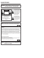
LC-20VM2 SHARP CORPORATION OSAKA, JAPAN PORTUGUÊS OPERATION MANUAL MODE D’EMPLOI MANUAL DE MANEJO MANUAL DE OPERAÇÃO ESPAÑOL FRANÇAIS LCD AV MONITOR MONITEUR AV À CRISTAUX LIQUIDES MONITOR AV LCD MONITOR AV DE TELA DE CRISTAL LÍQUIDO ENGLISH LC-20VM2 PRINTED IN JAPAN IMPRIMÉ AU JAPON IMPRESO EN JAPÓN IMPRESSO NO JAPÃO TINS-6901CEZZ TXXXX-A Important Information WARNING: TO REDUCE THE RISK OF FIRE OR ELECTRIC SHOCK, DO NOT EXPOSE THIS PRODUCT TO RAIN OR MOISTURE. CAUTION RISK OF ELECTRIC SHOCK. DO NOT OPEN CAUTION: TO REDUCE THE RISK OF ELECTRIC SHOCK, DO NOT REMOVE COVER. NO USER-SERVICEABLE PARTS INSIDE. REFER SERVICING TO QUALIFIED SERVICE PERSONNEL. The lightning flash with arrowhead symbol, within an equilateral triangle, is intended to alert the user to the presence of uninsulated “dangerous voltage” within the product’s enclosure that may be of sufficient magnitude to constitute a risk of electric shock to persons. The exclamation point within a triangle is intended to alert the user to the presence of important operating and maintenance (servicing) instructions in the literature accompanying the product. WARNING: FCC Regulations state that any unauthorized changes or modifications to this equipment not expressly approved by the manufacturer could void the user’s authority to operate this equipment. U.S.A. ONLY INFORMATION This equipment has been tested and found to comply with the limits for a Class A digital device, pursuant to Part 15 of the FCC Rules. These limits are designed to provide reasonable protection against harmful interference in a residential installation. This equipment generates, uses, and can radiate radio frequency energy and, if not installed and used in accordance with the instructions, may cause harmful interference to radio communications. However, there is no guarantee that interference will not occur in a particular installation. If this equipment does cause harmful interference to radio or television reception, which can be determined by turning the equipment off and on, the user is encouraged to try to correct the interference by one or more of the following measures: • • • • Relocate or adjust the receiving antenna. Increase the separation between the equipment and receiver. Connect the equipment into an outlet on a circuit different from that to which the receiver is connected. Consult the dealer or an experienced radio/TV technician for help. U.S.A. ONLY CAUTION: TO PREVENT ELECTRIC SHOCK, MATCH WIDE BLADE OF PLUG TO WIDE SLOT, FULLY INSERT. ENGLISH ENGLISH OPERATION MANUAL Contents Page Dear SHARP Customer ................................................. 2 Safety Precautions ........................................................ 2 Supplied Accessories ................................................... 4 Preparation ..................................................................... 5 Example of Application ................................................ 6 Listening with a Headphone .................................... 6 Names of Parts (Main Unit) .......................................... 7 Main Unit (Front View) .............................................. 7 Main Unit (Rear View) ............................................... 8 Names of Parts (Remote Control) ............................... 9 Remote control .......................................................... 9 Basic Operation ........................................................... 10 Turning on POWER ................................................. 10 Switching AV INPUT AV1/AV2/COMPONENT/ RGB .......................................................................... 10 Sound Volume ......................................................... 11 Power ON/OFF standby .......................................... 11 Page Adjustment ................................................................... 12 Adjusting the PICTURE settings ........................... 12 Adjusting the SOUND settings .............................. 14 Adjusting the PRESET settings ............................. 15 Adjusting the FINE SYNC Settings (RGB mode only) ..................................................... 16 Connecting to computer ............................................. 17 Connection Pin Assignments ................................ 18 RGB Input Signals (Recommended Timing) ........ 18 RS232C terminal specifications ............................ 19 Connecting to Video Equipment ............................... 22 Watching TV ............................................................ 22 Connecting with VIDEO Equipment ...................... 24 Troubleshooting .......................................................... 26 Specifications .............................................................. 27 Dimensional Drawings ................................................ 28 Dear SHARP Customer Thank you for your purchase of the Sharp LCD product. To ensure safety and many years of trouble-free operation of your product, please read the Safety Precautions carefully before using this product. Safety Precautions Electricity is used to perform many useful functions, but it can also cause personal injuries and property damage if improperly handled. This product has been engineered and manufactured with the highest priority on safety. However, improper use can result in electric shock and/or fire. In order to prevent potential danger, please observe the following instructions when installing, operating and cleaning the product. To ensure your safety and prolong the service life of your LCD product, please read the following precautions carefully before using the product. 1. Read instructions—All operating instructions must be read and understood before the product is operated. 2. Keep this manual in a safe place—These safety and operating instructions must be kept in a safe place for future reference. 3. Observe warnings—All warnings on the product and in the instructions must be observed closely. 4. Follow instructions—All operating instructions must be followed. 5. Cleaning—Unplug the power cord from the AC outlet before cleaning the product. Use a damp cloth to clean the product. Do not use liquid cleaners or aerosol cleaners. 6. Attachments—Do not use attachments not recommended by the manufacturer. Use of inadequate attachments can result in accidents. 7. Water and moisture—Do not use the product near water, such as bathtub, washbasin, kitchen sink and laundry tub, swimming pool and in a wet basement. 8. Stand—Do not place the product on an unstable cart, stand, tripod or table. Placing the product on an unstable base can cause the product to fall, resulting in serious personal injuries as well as damage to the product. Use only a cart, stand, tripod, bracket or table recommended by the manufacturer or sold with the product. When mounting the product on a wall, be sure to follow the manufacturer’s instructions. Use only the mounting hardware recommended by the manufacturer. 9. When relocating the product placed on a cart, it must be moved with utmost care. Sudden stops, excessive force and uneven floor surface can cause the product to fall from the cart. 10. Ventilation—The vents and other openings in the cabinet are designed for ventilation. Do not cover or block these vents and openings since insufficient ventilation can cause overheating and/or shorten the life of the product. Do not place the product on a bed, sofa, rug or other similar surface, since they can block ventilation openings. This product is not designed for built-in installation; do not place the product in an enclosed place such as a bookcase or rack, unless proper ventilation is provided or the manufacturer’s instructions are followed. US 2 11. Power source—This product must operate on a power source specified on the specification label. If you are not sure of the type of power supply used in your home, consult your dealer or local power company. For units designed to operate on batteries or another power source, refer to the operating instructions. 12. Power cord protection—The power cords must be routed properly to prevent people from stepping on them or objects from resting on them. Check the cords at the plugs and product. 13. Regarding AC adapter and power cord a.If the AC adapter is misplaced or needs to be replaced, obtain the same type of adapter from a Sharp service center or your dealer. b.If the product is to be used overseas, contact a Sharp service center or your dealer and obtain a power cord that complies with the applicable safety regulations of the country in which the product will be used. 14. The LCD panel used in this product is made of glass. Therefore, it can break when the product is dropped or applied with impact. Be careful not to be injured by broken glass pieces in case the LCD panel breaks. 15. Overloading—Do not overload AC outlets or extension cords. Overloading can cause fire or electric shock. 16. Entering of objects and liquids—Never insert an object into the product through vents or openings. High voltage flows in the product, and inserting an object can cause electric shock and/or short internal parts. For the same reason, do not spill water or liquid on the product. 17. Servicing—Do not attempt to service the product yourself. Removing covers can expose you to high voltage and other dangerous conditions. Request a qualified service person to perform servicing. 18. Repair—If any of the following conditions occurs, unplug the power cord from the AC outlet, and request a qualified service person to perform repairs. a.When the power cord or plug is damaged. b.When a liquid was spilled on the product or when objects have fallen into the product. c. When the product has been exposed to rain or water. d.When the product does not operate properly as described in the operating instructions. Do not touch the controls other than those described in the operating instructions. Improper adjustment of controls not described in the instructions can cause damage, which often requires extensive adjustment work by a qualified technician. e.When the product has been dropped or damaged. f. When the product displays an abnormal condition. Any noticeable abnormality in the product indicates that the product needs servicing. 19. Replacement parts—In case the product needs replacement parts, make sure that the service person uses replacement parts specified by the manufacturer, or those with the same characteristics and performance as the original parts. Use of unauthorized parts can result in fire, electric shock and/or other danger. 20. Safety checks—Upon completion of service or repair work, request the service technician to perform safety checks to ensure that the product is in proper operating condition. 21. Wall or ceiling mounting—When mounting the product on a wall or ceiling, be sure to install the product according to the method recommended by the manufacturer. 22. Heat sources—Keep the product away from heat sources such as radiators, heaters, stoves and other heat-generating products (including amplifiers). The LCD panel is a very high technology product with 921,600 thin film transistors, giving you fine picture details. Occasionally, a few non-active pixels may appear on the screen as a fixed point of blue, green or red. Please note that this does not affect the performance of your product. 3 US Supplied Accessories Make sure the following accessories are provided with the product. Operation Manual (×1) (TINS-6901CEZZ) Wireless Remote Control (×1) (RRMCG1459CESA) ON/OFF LC-20VM2 AV INPUT MUTE MENU VOL + SELECT PORTUGUÊS OPERATION MANUAL MODE D’EMPLOI MANUAL DE MANEJO MANUAL DE OPERAÇÃO VOL – ESPAÑOL FRANÇAIS LCD AV MONITOR MONITEUR AV À CRISTAUX LIQUIDES MONITOR AV LCD MONITOR AV DE TELA DE CRISTAL LÍQUIDO ENGLISH SELECT AC cord (×1) (QACCD3088CEZZ) Cable clamp (×2) (LHLDW1028CEZZ) 78- 3/4" (2m) *Product shape varies in some countries US 4 AC adapter (×1) (UADP-0214CEZZ) AV cable (×1) (QCNW-1335TAZZ) 78- 3/4" (2m) 59- 1/16" (1.5m) Size AAA dry battery (×2) (UBATU0026GEZZ) Din-D/sub RS232C cable (×1) (QCNW-5288CEZZ) Preparation Power Connection Connect to DC input terminal of the product. Plug into AC outlet. Press the button before disconnecting the AC adapter from the main unit. Household power outlet *AC cord DC input terminal (DC13V) POWER INPUT DC13V AC adapter * Product shape varies in some countries Batteries for Remote Control If the remote control fails to operate monitor functions, replace the batteries in the remote control. 1 Open the battery cover. ■ Slide the cover while pressing down. 2 Insert batteries (two size-AAA batteries, supplied with product). 3 Close the battery cover. ■ Place batteries with their terminals corresponding to the (+) and (–) indications in the battery compartment. Caution Cautions regarding batteries Improper use of batteries can result in a leakage of chemicals and/or explosion. Be sure to follow the instructions below. • Place batteries with their terminals corresponding to the (+) and (–) indications. • Different types of batteries have different characteristics. Do not mix batteries of different types. • Do not mix old and new batteries. Mixing old and new batteries can shorten the life of new batteries and/or cause old batteries to leak chemicals. • Remove batteries as soon as they are non-operable. Chemicals that leak from batteries can cause a rash. If chemical leakage is found, wipe with a cloth. • The batteries supplied with the product may have a shorter life expectancy due to storage conditions. • If the remote control is not used for an extended period of time, remove batteries from the remote control. 5 US Preparation Removing and mounting the back cover ■ Removal • Remove the back cover when inserting the cords into the terminals. • To remove the back cover, gently pull the part marked forward. 1 ■ Mounting • Insert the four hooks (1) into the cabinet. • Making the back cover bulge forward, insert the four hooks (2) into the cabinet. • Press on the marked parts (3) until the two hooks on the bottom of the cover are locked in place with a click. 2 2 3 Clamping the connection cords • When mounting the cover, clamp the cords using the included cord holders (cable clamps) so that they do not get caught. • Stick the two cable clamps near the CONTROL terminal and the DC input terminal, then insert cables into the main unit. Cable Clamp Example of Application Listening with a Headphone ■ Plug the headphone mini-plug into the headphone jack located on the front side of the set. HEAD PHONE Note US 6 MENU — The headphone is not included in the supplied accessories. Names of Parts (Main Unit) Main Unit (Front View) Speakers Front Control section HEAD PHONE 1 1 2 3 4 2 Remote sensor window HEAD PHONE jack MENU button VOL (+)/(–) buttons MENU 3 − VOL 4 + SELECT AV INPUT POWER POWER 5 6 7 8 5 SELECT buttons 6 AV INPUT button 7 POWER switch 8 POWER indicator * MENU button, VOL (+)/(–) buttons, SELECT buttons and AV INPUT button have the same function as those on the remote control. This manual describes button functions by referring to the buttons on the remote control. 7 US Names of Parts (Main Unit) Main Unit (Rear View) Rear Speaker (woofer) Rear terminal section NTSC / PAL / SECAM AV INPUT 1 CONTROL R AUDIO L VIDEO S-VIDEO NTSC / PAL AV INPUT 2 / AV OUT AUDIO VIDEO R L COMPONENT(INPUT) AUDIO VIDEO Y PB(CB) PR(CR) R L POWER INPUT DC13V AUDIO INPUT RGB INPUT (VGA60Hz) 1 2 3 4 5 6 1 RGB input terminal 2 AUDIO input terminal 3 CONTROL terminal 4 AUDIO input terminal (AV INPUT 1) 5 VIDEO input terminal (AV INPUT 1) 6 S-VIDEO input terminal (AV INPUT 1) US 8 7 8 9 0 q 7 AUDIO input terminal (AV INPUT 2/AV OUT) 8 VIDEO input terminal (AV INPUT 2/AV OUT) 9 VIDEO input terminal (COMPONENT) 0 AUDIO input terminal (COMPONENT) q DC input terminal * 7 and 8 can also be used as video/audio output terminals Names of Parts (Remote Control) Remote control Infrared transmitter window ON/OFF Power ON/OFF button MUTE Sound MUTE button MENU AV INPUT AV INPUT button MENU button SELECT VOL – VOL + SELECT buttons SELECT VOL (+)/(–) buttons ■ The front control section of the main unit is also provided with the AV INPUT, SELECT, VOL (+)/(–) and MENU buttons. * This manual describes button functions by referring to the buttons on the remote control. Front Control section HEAD PHONE ON/OFF AV INPUT MUTE MENU − MENU ON/OFF AV INPUT SELECT VOL – + MUTE MENU SELECT ON/OFF AV INPUT SELECT VOL + SELECT VOL VOL – MUTE MENU POWER POWER ON/OFF AV INPUT SELECT VOL + SELECT AV INPUT VOL – SELECT VOL + SELECT MUTE MENU VOL – VOL + SELECT 9 US Basic Operation Turning on POWER ■ Press POWER, located on the front side of the main unit. ■ When the Power indicator is red, press the POWER ON/OFF on the remote control to turn on the monitor. The Power indicator changes from red to green. Control section of main unit ▼ Screen (Video 1 mode) AV1 PAL 1Input mode indication disappears after three seconds. HEAD PHONE MENU − VOL + SELECT AV INPUT POWER Press POWER Power indicator Switching AV INPUT AV1/AV2/COMPONENT/RGB ON/OFF ■ Turn on the power of the connected video equipment. ■ Press AV INPUT and select the applicable input source. The screen displays AV1, AV2, COMPONENT or RGB at the upper right corner each time AV INPUT is pressed. MUTE AV INPUT Note MENU 1. AV input mode indication remains for three seconds. 2. To change the AV input mode, press AV INPUT while the AV input mode is displayed (within 3 seconds). ◆ AV1: Video equipment connected to the AV1 input terminals. S-video input terminal is additionally provided for the AV1 input. If both Svideo and normal video terminal is connected with cables, the S-video input terminal takes precedence. ◆ AV2: Video equipment connected to the AV2 input terminals. ◆ COMPONENT: Video equipment connected to the component input terminals. ◆ RGB: Personal computer connected to the RGB input terminal. SELECT VOL – VOL + SELECT ■ Each time AV INPUT is pressed, the indication at the upper right corner on the screen changes in the following order. ▼ Screen Initial mode (AV1) AV1 mode AV2 mode AV1 AV2 PAL PAL COMPONENT mode COMPONENT RGB mode RGB AV INPUT * 1st push: Displays the current AV input mode ■ When the AV2 output function is in use, the mode switches among COMPONENT, RGB and AV1. Note US 10 The contents displayed on the screen differ according to the contents of the input signal. Basic Operation Sound Volume ON/OFF AV INPUT MUTE MENU ■ Press VOL (+) to increase sound volume. The segment of indicator increases. VOLUME 5‰ ■ Press VOL (–) to decrease sound volume. The segment of indicator decreases. VOLUME 1‰ SELECT To mute sound VOL – VOL + ■ Press MUTE to temporarily turn off the sound. Screen display flashes. VOLUME ‰ SELECT ■ Press MUTE or VOL (+)/(–) to turn the sound back to the previous level. VOLUME 3‰ Power ON/OFF standby ON/OFF AV INPUT MUTE ■ To turn off the monitor, press Power ON/OFF. The Power indicator will turn red. ■ To turn the monitor back on, press Power ON/OFF again. The Power indicator will turn green. MENU SELECT VOL – VOL + SELECT 11 US Adjustment Adjusting the PICTURE settings 1 Press MENU to display the Menu screen. ON/OFF MUTE MENU AV INPUT 2 Press SELECT to move the cursor to PICTURE. 3 Press VOL (+)/(–) to display the PICTURE Menu screen. 4 Press SELECT to move the cursor and select the desired adjustment item. All of adjustment item is shown in the diagram on page 13. 5 Press VOL (+)/(–) to display the screen for the selected adjustment item. SELECT VOL – VOL + SELECT 6 Note MENU PICTURE SOUND PRESET MENU PICTURE SOUND PRESET PICTURE AV1 CONTRAST [ ‰] TINT [ ‰] COLOR [ ‰] BLACK LEVEL [ ‰] SHARPNESS [ ‰] RED [ ‰] BLUE [ ‰] COLOR SYSTEM [ AUTO] RESET SELECT: • ENTER :( • ) EXIT: MENU PICTURE AV1 CONTRAST [ ‰] TINT [ ‰] COLOR [ ‰] BLACK LEVEL [ ‰] SHARPNESS [ ‰] RED [ ‰] BLUE [ ‰] COLOR SYSTEM [ AUTO] RESET SELECT: • ENTER :( • ) EXIT: MENU COLOR 3‰ SELECT: • ADJUST:( • ) EXIT: MENU Press VOL (+)/(–) to make adjustment. The TINT indication appears only when NTSC (N358/N443) broadcasts are received. Switching the System Set the system to AUTO for normal reception. The AUTO mode automatically detects the receiving signal system and changes the reception system of the set. When the picture or sound is not stable, switching to an appropriate system may improve the picture or sound quality. US 12 Adjustment AV1,2, COMPONENT mode Selected item CONTRAST 3‰ TINT – + ‰ COLOR 3‰ BLACK LEVEL – ‰ + SHARPNESS ‰ – + RED – + – + ‰ BLUE ‰ COLOR SYSTEM Note [ AUTO] Press VOL (–) Press VOL (+) Decrease contrast Increase contrast – + Toward purple Toward green Lower color intensity Higher color intensity – + Less bright More bright – + Soft picture Hard picture – + Less red level More red level – + Less blue level More blue level Press VOL (+) to select color system. → AUTO → N358 → N443 → PAL → PAL-M → SECAM The COMPONENT mode doesn’t contain TINT and COLOR SYSTEM. PAL60 is also displayed when the signal is received in PAL system. RGB mode Selected item CONTRAST 3‰ BLACK LEVEL – ‰ + RED – + – + ‰ BLUE ‰ Note Press VOL (–) Press VOL (+) Decrease contrast Increase contrast – + Less bright More bright – + Less red level More red level – Less blue level + More blue level If no button is pressed for more than approximately 30 seconds, the MENU setting is automatically cancelled and the display returns to the initial screen. If VOL (+)/(–) is pressed after RESET is selected with SELECT, the factory setting is restored. 13 US Adjustment Adjusting the SOUND settings 1 Press MENU to display the Menu screen. ON/OFF MENU PICTURE SOUND PRESET MUTE MENU AV INPUT 2 Press SELECT to move the cursor to SOUND. MENU PICTURE SOUND PRESET 3 Press VOL (+)/(–) to display the SOUND Menu screen. SOUND SPEAKER [ON] LINE OUT [ STABLE] TREBLE [ ‰] BASS [ ‰] BALANCE [ ‰] RESET 4 Press SELECT to move the cursor and select the desired adjustment item. All of adjustment item is shown in the diagram below. 5 Press VOL (+)/(–) to display the selected adjustment screen. SELECT VOL – VOL + SELECT SOUND SPEAKER [ON] LINE OUT [ STABLE] TREBLE [ ‰] BASS [ ‰] BALANCE [ ‰] RESET BASS – + ‰ SELECT: • ADJUST:( • ) EXIT: MENU 6 When the RESET is selected while the SOUND Menu screen is displayed, adjusted items are canceled and the default settings (factory settings) are restored. Note Selected item Press VOL (–) – + – + ‰ BASS – + Lower treble level Higher treble level – ‰ Lower bass level ‰ Shift center of sound toward left BALANCE Press VOL (+) Press VOL (+) to select speaker and Line out settings SPEAKER [ON] SPEAKER [OFF] LINE OUT [STABLE] LINE OUT [VARIABLE] SPEAKER [ON] LINE OUT [ STABLE] S L C TREBLE Press VOL (+)/(–) to make adjustment. + Higher bass level ‰~L3‰ ‰~R3‰ Shift center of sound toward right Note • If no button is pressed for more than approximately 30 seconds, the MENU setting is automatically canceled and the display returns to the initial screen. • When AV2 is set to “OUT”, it is possible to control the volume from AV2 and the turning on and off of the builtin speakers. US 14 Adjustment Adjusting the PRESET settings ■ The preset items can be set by the user. ON/OFF 1 Press MENU to display the Menu screen. MENU PICTURE SOUND PRESET 2 Press SELECT to move the cursor to PRESET. MENU PICTURE SOUND PRESET 3 Press VOL (+)/(–) to display the PRESET screen. PRESET BRIGHTNESS UPSIDE RIGHT/LEFT AV2 IN/OUT AV1 LINE SCREEN MODE MUTE MENU AV INPUT SELECT VOL – VOL + SELECT [BRIGHT] [NORMAL] [NORMAL] [IN ] [NORMAL] [MODE 1] SELECT: • ENTER :( • ) EXIT: MENU 4 Selected item Check the factory setting of each item on the PRESET screen. The user can change the settings by using SELECT and VOL (+)/ (–) buttons. Factory setting Setting change BRIGHTNESS [BRIGHT] Maximum brightness [NORMAL] Brightness 60% → Suitable for viewing in well-lit areas. Saves energy. [DARK] Brightness 20% → Sufficiently bright when viewing in dim areas. UPSIDE [NORMAL] Normal vertical image orientation [DOWN] Inverted image → To display images upside down for special uses. ABC RIGHT/LEFT [NORMAL] Normal horizontal image orientation [MIRROR] Mirror image → To display mirror images for special uses. CBA AV2 IN/OUT [IN] AV input 2 in input mode [OUT] AV input 2 changes to AV output mode → Video/audio signals entering AV input 1 is output from AV output 2 terminals to allow recording. * Setting change possible only for AV INPUT 2 AV1 LINE [NORMAL] The audio signals entering from the AUDIO L and R terminals are output from the left and right speakers respectively. [MONO] Only the audio signals entering from the AUDIO L terminal are output from the left and right speakers. SCREEN MODE [MODE 1] MODE 1 is a simple scan conversion mode and is suited for still pictures. [MODE 2] MODE 2 is a calculated scan conversion mode and is suited for normal pictures. * The scan conversion modes work in PAL and SECAM. Note • The Menu screen and the screen selected on the Menu screen remains on the display for 30 seconds. If no button is pressed during the 30 seconds, the display returns to the initial screen. • The signal input from the S-VIDEO input terminal is not output from the AV OUT terminal for monitoring. 5 After changing PRESET items, press MENU to exit from the Menu screen and return to the initial screen. 15 US Adjustment Adjusting the FINE SYNC Settings(RGB mode only) ■ FINE SYNC settings can be adjusted in RGB mode only. ON/OFF 1 Press MENU to display the Menu screen. MENU PICTURE FINE SYNC SOUND PRESET 2 Press SELECT to move the cursor to FINE SYNC. MENU PICTURE FINE SYNC SOUND PRESET 3 Press VOL(+)/(–) to display the FINE SYNC screen. FINE SYNC CLOCK PHASE H-POS V-POS RESET [ [ [ [ ‰] ‰] ‰] ‰] Press SELECT to move the cursor and select the desired adjustment item. FINE SYNC CLOCK PHASE H-POS V-POS RESET [ [ [ [ ‰] ‰] ‰] ‰] MUTE AV INPUT MENU SELECT VOL – VOL + SELECT 4 5 6 Selected item Press VOL (–) Set to the position at which there is the least noise 1‰ Set to the position at which there is the least noise – + PHASE H-POS ‰ 16 1‰ SELECT: • ( ADJUST: • ) EXIT: MENU Press VOL (+) – + – + Move the on-screen image to the left – + Move the on-screen image to the right – + Move the on-screen image upward – + Move the on-screen image downward ‰ V-POS PHASE Press VOL(+)/(–) to make adjustment. ‰ CLOCK US Press VOL(+)/(–) to display the screen for the selected adjustment item. Connecting to computer This LCD AV monitor can be used as the monitor of personal computer. This unit can be used with the following type of computer and display mode. Horizontal scanning frequency Display mode (Horizontal dots × Vertical lines) Vertical frequency Computer IBM PC(DOS/V, PC/V, PC/AT) and compatible computers 640×480 Clock frequency Note 25.175 MHz VGA 31.4688 kHz 59.9405 Hz ■ Push off the hole cover for PC connection when the back cover is set. AUDIO INPUT RGB INPUT (VGA60Hz) Hole cover To AUDIO input terminal To AUDIO output terminal (commercially available) (commercially available) To RGB input terminal Note To RGB output terminal No RGB connection cable or PC audio cable is included. Use commercially available cables. Handling of the RGB Connection Cable ■ Align the pins of this unit and those of the RGB connection cable used to connect the computer and insert, then securely fasten with the screws located at both ends. 17 US Connecting to computer Connection Pin Assignments RGB input terminal: 15-pin mini D-sub female connector 5 10 4 3 9 2 8 Pin No. 1 2 3 4 5 6 7 8 1 7 6 Pin No. 9 10 11 12 13 14 15 Signal Analog input(red) Analog input(green) Analog input(blue) Not connected Composite sync GND (Analog red) GND (Analog green) GND (Analog blue) Signal Not connected GND GND Not connected Horizontal sync signal Vertical sync signal Not connected 15 14 13 12 11 CONTROL terminal: 9-pin mini Din female connector Pin No. 1 2 3 4 5 6 7 8 9 8 9 7 6 3 4 5 2 1 Signal RD SD SG RS - Name I/O Receive Data Send Data Reference Not connected Connected to internal Connected to internal Not connected Connected to internal Not connected Connected to internal Not connected Not connected Input Output Signal Ground Request to send Output circuit circuit circuit circuit RGB Input Signals (Recommended Timing) Input signal Video signal: Analog input 0 to 0.7Vp-p 75Ω terminal (positive polarity) Horizontal synchronizing signal: TTL level (negative polarity) Vertical synchronizing signal: TTL level (negative polarity) MODE VIDEO Video signal time chart IBM, DOS/V type 1H VIDEO SIGNAL H-SYNC HORIZONTAL SYNC SIGNAL a b c d VIDEO SIGNAL VERTICAL SYNC SIGNAL w x y z 1V V-SYNC FRONT PORCH SYNC BACK PORCH VIDEO PERIOD 1H a b c d 1dot 1/H 1/dot LEVEL SYNC POLARITY FRONT PORCH w SYNC x BACK PORCH y VIDEO PERIOD z 1V 1/V LEVEL SYNC POLARITY US 18 dot line LEVEL TYPE dot dot dot dot dot µs ns kHz MHz +/– H H H H H ms Hz +/– IBM VGA GRAPHIC 640 480 0.7Vp-p, 75Ω load RGB 50 640 800 31.7776 39.7219 31.4688 25.175 TTL – 32 480 525 16.6832 59.9405 TTL – Connecting to computer RS232C terminal specifications ■ When a program is set, the LCD Monitor can be controlled from the computer using the RS232C terminal. The input signal (computer/video) can be selected, the volume can be adjusted and various other adjustments and settings can be made, enabling automatic programed playing. ■ Attach an RS232C cable cross-type (commercially available) to the supplied Din-D/sub RS232C for the connections. This operation system should be used by a person who is accustomed to using computers. Note Connections Connect this unit with the RS232C terminal of the computer. Send the control commands from the computer via the RS232C terminal. Mount the cable clamps when connecting cables to the rear terminal section (see page 6). Note CONTROL Din-D/sub RS232C cable (supplied) RS232C cable cross-type (commercially available) RS232C terminal The specifications of the RS232C terminal of this unit are described below. 8 9 7 6 3 Pin No. 1 2 3 4 5 6 7 8 9 Signal - RD SD - SG - RS - - 4 5 2 1 Communication conditions Set the RS232C communications settings on the computer to match the LCD Monitor’s communications conditions. The LCD Monitor’s communications settings are as follows: Baud rate Data length Parity bit Stop bit Flow control 9,600 bps 8 bits None 1bit None 19 US Connecting to computer Communication procedure Send the control commands from the computer via the RS232C terminal. The LCD Monitor operates according to the received command and sends a response message to the computer. Do not send multiple commands at the same time. Wait until the computer receives the OK response before sending the next command. Command format C1 C2 C3 C4 P1 P2 P3 P4 Command 4-digits Parameter 4-digits Return code (0DH) Response code format Normal response O K Return code (0DH) Problem response (communication error or incorrect command) E R R Return code (0DH) When more than one code is being sent, send each command only after the OK response code for the previous command from the LCD Monitor is verified. Note When using the computer control function of the LCD Monitor, the LCD Monitor operating status cannot be read to the computer. Therefore, confirm the status by transmitting the display commands for each adjustment menu and checking the status with the On-screen Display. If the LCD Monitor receives a command other than a menu display command, it will execute the command without displaying the On-screen Display. Commands Example: The AV input mode set to PAL after switching the display mode to AV1. Computer LCD Monitor I V E D _ _ _ 1 O K M E S Y _ _ _ 2 O K CONTROL CONTENTS POWER OFF POWER ON AV1 AV2 COMPONENT RGB INPUT CHECK AUTO PAL SECAM NTSC 4.43 NTSC 3.58 PAL-M US 20 C1 P P I I I I I M M M M M M COMMAND C2 C3 O W O W V E V E C E R G C H E S E S E S E S E S E S C4 R R D D D B K Y Y Y Y Y Y P1 _ _ _ _ _ _ _ _ _ _ _ _ _ PARAMETER P2 P3 _ _ _ _ _ _ _ _ _ _ _ _ _ _ _ _ _ _ _ _ _ _ _ _ _ _ P4 0 1 1 2 1 1 0 1 2 3 4 5 6 Connecting to computer CONTROL CONTENTS AV1 CONTRAST(0 ~ 60) AV1 BLACK LEVEL(–30 ~ +30) AV1 COLOR(0 ~ 60) AV1 TINT(–30 ~ +30) AV1 SHARPNESS(–30 ~ +30) AV1 RED(–30 ~ +30) AV1 BLUE(–30 ~ +30) AV1 DISPLAY AV1 RESET AV2 CONTRAST(0 ~ 60) AV2 BLACK LEVEL(–30 ~ +30) AV2 COLOR(0 ~ 60) AV2 TINT(–30 ~ +30) AV2 SHARPNESS(–30 ~ +30) AV2 RED(–30 ~ +30) AV2 BLUE(–30 ~ +30) AV2 DISPLAY AV2 RESET COMPONENT CONTRAST(0 ~ 60) COMPONENT BLACK LEVEL(–30 ~ +30) COMPONENT COLOR(–30 ~ +30) COMPONENT SHARPNESS(–30 ~ +30) COMPONENT RED(–30 ~ +30) COMPONENT BLUE(–30 ~ +30) COMPONENT DISPLAY COMPONENT RESET VOLUME(0 ~ 60) MUTE OFF MUTE ON TREBLE BASS BALANCE SOUND DISPLAY SOUND RESET RGB CONTRAST(0 ~ 60) RGB BLACK LEVEL(–30 ~ +30) RGB RED(–30 ~ +30) RGB BLUE(–30 ~ +30) RGB DISPLAY RGB RESET CLOCK(–10 ~ +10) PHASE(0 ~ 20) H-POS(–20 ~ +20) V-POS(–20 ~ +20) FINE SYNC DISPLAY FINE SYNC RESET INVERT OFF INVERT ON REVERSE OFF REVERSE ON INPUT DISPLAY OFF INPUT DISPLAY ON DISPLAY Note C1 V V V V V V V V V V V V V V V V V V C C C C C C C C V M M A A A A A R R R R R R I I I I I I I I I I I I S COMMAND C2 C3 A P A B A C A T A S A R A B A R A R B P B B B C B T B S B R B B B R B R A P A B A C A S A R A B A R A R O L U T U T A T A B A B A R A R A P A B A R A B A R A R N C N P A H A V A R A R M I M I M R M R M D M D Y S C4 I R O I H D E E E I R O I H D E E E I R O H D E E E A E E E A L E E I R D E E E L H P P E E N N E E I I P1 _ _ _ _ _ _ _ _ _ _ _ _ _ _ _ _ _ _ _ _ _ _ _ _ _ _ _ _ _ _ _ _ _ _ _ _ _ _ _ _ _ _ _ _ _ _ _ _ _ _ _ _ E _ PARAMETER P2 P3 * * * * * * * * * * * * * * _ _ _ _ * * * * * * * * * * * * * * _ _ _ _ * * * * * * * * * * * * _ _ _ _ _ * _ _ _ _ * * * * * * _ _ _ _ * * * * * * * * _ _ _ _ * * * * * * * * _ _ _ _ _ _ _ _ _ _ _ _ _ _ _ _ _ P4 * * * * * * * 0 1 * * * * * * * 0 1 * * * * * * 0 1 * 0 1 * * * 0 1 * * * * 0 1 * * * * 0 1 0 1 0 1 0 1 _ 0 If a dash (_) appears in the parameter column, enter a space. If an asterisk (*) appears, enter a value in the range indicated in brackets under CONTROL CONTENTS. 21 US Connecting to Video Equipment Watching TV ■ To view a TV broadcast on the LCD monitor, the set-top box must be used with a TV tuner, satellite tuner or VCR. Refer to the diagram below for wiring. Note Refer to the manual how to connect these tuner to the room antenna terminal. Via TV Via Satellite TV, Pay TV AUDIO R AUDIO L VIDEO To VIDEO/AUDIO input terminal VIDEO To VIDEO/AUDIO output terminal VCR, TV TUNER 22 L To VIDEO/AUDIO input terminal To VIDEO/AUDIO output terminal US R SATELLITE TUNER, SET TOP BOX(FOR PAY TV) Connecting to Video Equipment Via Web TV, Game Unit AUDIO R L VIDEO S-VIDEO To S-VIDEO input terminal To VIDEO/AUDIO input terminal To VIDEO/AUDIO output terminal To S-VIDEO output terminal SET TOP BOX(WEB TV) GAME UNIT 23 US Connecting to Video Equipment Connecting with VIDEO Equipment ■ This LCD AV monitor can be connected with the most of video equipment as follows. Digital Video Disc COMPONENT(INPUT) Y VIDEO PB(CB) PR(CR) AUDIO R L To VIDEO input terminal of COMPONENT To AUDIO input terminal of COMPONENT To VIDEO output terminal of COMPONENT To AUDIO output terminal of COMPONENT DVD TUNER/BAND AUX 1 AUX 2 AUX 3 SURROUND ON/OFF DVD PLAYER US 24 Connecting to Video Equipment Video, Game unit AV INPUT 1 AV INPUT 2 AUDIO R AUDIO L VIDEO S-VIDEO R L To S-VIDEO input terminal To VIDEO/AUDIO input terminal VIDEO To VIDEO/AUDIO input terminal To S-VIDEO output terminal To VIDEO/AUDIO output terminal VIDEO CAMERA ETC. To VIDEO/AUDIO output terminal GAME UNIT 25 US Troubleshooting Problem No image on screen, and no sound from speakers. Check item Pages • Make sure AC power cord plug is securely inserted in AC power outlet and AC adapter. • Make sure AC adapter’s DC output is securely connected to main unit’s DC input terminal. • Make sure main unit’s main power switch is turned on. • Make sure AV input is properly set. • Make sure cables are correctly connected to rear terminal section of LCD monitor. • Make sure remote control batteries have not worn out. • Make sure the unit is not in the standby mode (power indicator is red). 5 10 10 22 • Make sure cables are correctly connected. 22 • Check Color and Tint adjustments. (NTSC ONLY) • Make sure Contrast and Black Level adjustments are not set too high. • Check that Red and Blue adjustments are near the center. • Check component video input cable. 13 13 • Make sure cables are properly connected to rear terminal section of LCD monitor. • Check Sound setting. • Make sure sound is not muted. • Make sure headphone is not connected. 22 • Check to see if Brightness adjustment is not set to DARK. Screen brightness can be set to three levels (DARK, NORMAL and BRIGHT). • Make sure Contrast and Brightness adjustments are not set too low. • Lamp may have reached the end of life. (Contact a Sharp service shop for lamp replacement.) 15 • Check Color adjustment. • Make sure proper color system is set. • In the case of component mode, check to make sure PB (CB) and PR (CR) signals are input. 13 13 • Check to see if batteries in remote control have sufficient power. • Check to make sure (+) and (–) side of batteries are properly positioned in remote control. • Make sure infrared transmitter window is not receiving strong light such as light from fluorescent lamps. 5 5 5 11 Speakers produce sound, but no image on screen. Image is too light or improperly tinted. 13 24 14 11 6 Image is displayed, but no sound from speakers. Image is too dark. 13 No colors on image. Remote control does not work. US 26 5 Specifications ITEM LCD Size (Diagonal) Number of pixel Low reflection Brightness Viewable angle VIDEO AUDIO INTERFACES (TERMINALS) POWER SUPPLY APPEARANCE LC-20VM2 Left to right Upper to lower Life of back light System Digital comb filter for PAL/SECAM 3D Y/C separator for NTSC Wide-band chroma IC Gamma correction circuit Line scanning for PAL/SECAM Output Speaker Full range Woofer AV input 1 AV input 2 Component input RGB input Control Headphone jack DC operation AC operation Power consumption Exterior color Outside dimensions Net weight ACCESSORIES Note Remote control AC adapter Operation manual AC cord AV cable Cable clamp Din-D/sub RS232C cable 20" (Approx. 500 mm) 921,600 = 640(H) × 3(RGB) × 480(V) Non-glare 400cd/m2 (at normally white) 120° 100° 40,000 hours (at normal mode) N358/N443/PAL/PAL-M/PAL60/SECAM Curtailed System 4.0 W 1-3/ 16" [3 cm] × 1- 37/ 64" [4 cm] Oval, 2 pcs. 3-5/ 32" [8 cm] Round, 1 pc. Audio R/L, Video S-terminal/RCA composite Audio R/L, Video RCA composite Audio R/L, Video Y/PB (CB)/PR (CR) Audio φ3.5 R/L VGA (60Hz) computer input RS232C Mini-jack for stereo DC 13V AC100~240V with AC adapter 50.7 W Silver 18-1/ 8" (W) × 17- 9/ 64" (H) × 7-3 /32" (D) (with stand) [460 (W) × 435 (H) × 180 (D) mm] 18-1/ 8" (W) × 15- 63/ 64" (H) × 1-61/ 64" (D) (without stand) [460 (W) × 406 (H) × 49.5 (D) mm] 19.16 lbs [8.7 kg] (with stand) 13.87 lbs [6.3 kg] (without stand) Infrared wireless type Auto-wide type language: English/French/Spanish/Portugues 78-3/ 4" [2 m] 59-1/ 16" [1.5 m] 2 pcs 1 pc Above specification might be changed without notice. 27 US Dimensional Drawings 18-1/8" (460 mm) 1-61/64" (49.5 mm) 15-53/64" (402 mm) /32" (10.5 mm) 17-9/64" (435 mm) 63 7-3/32" (179.9 mm) 15- /64" (406 mm) 13 1-23/32" (44 mm) 7-8/32" (180 mm) US 28 Memo 29 US