1
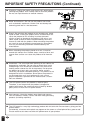
SHARP ELECTRONICS CORPORATION
Sharp Plaza, Mahwah, New Jersey 07430-2135
SHARP CORPORATION
Printed on post-consumer recycled paper.
Imprimé sur du papier recyclé.
Impreso en papel reciclado.
Impresso em papel reciclado pós utilização.
Printed in Japan
Imprimé au Japon
Impreso en Japón
Impresso no Japão
TINS-A156WJN1
02P08-JKG
FRANÇAIS
ENGLISH
OPERATION MANUAL
MODE D’EMPLOI
MANUAL DE OPERACIÓN
MANUAL DE OPERAÇÃO
ESPAÑOL
LIQUID CRYSTAL TELEVISION
TÉLÉVISEUR ACL
TELEVISOR CON PANTALLA
DE CRISTAL LÍQUIDO
TELEVISOR DE CRISTAL
LÍQUIDO
PORTUGUÊS
LC-13E1U/LC-15E1U
LC-13E1U
LC-15E1U
ENGLISH
LC-13E1U
LC-15E1U
LIQUID CRYSTAL TELEVISION
ENGLISH
OPERATION MANUAL
IMPORTANT:
To aid reporting in case of loss or theft, please
record the TV’s model and serial numbers in the
space provided. The numbers are located at the
rear of the TV.
Model No.:
Serial No.:
U.S.A. ONLY
IMPORTANT INFORMATION
WARNING:
TO REDUCE THE RISK OF FIRE OR ELECTRIC SHOCK, DO
NOT EXPOSE THIS PRODUCT TO RAIN OR MOISTURE.
CAUTION
RISK OF ELECTRIC SHOCK.
DO NOT OPEN.
CAUTION: TO REDUCE THE RISK OF ELECTRIC SHOCK,
DO NOT REMOVE COVER (OR BACK).
NO USER-SERVICEABLE PARTS INSIDE.
REFER SERVICING TO QUALIFIED SERVICE
PERSONNEL.
The lightning flash with arrowhead symbol, within an equilateral triangle, is intended to alert
the user to the presence of
uninsulated “dangerous voltage”
within the product’s enclosure
that may be of sufficient
magnitude to constitute a risk of
electric shock to persons.
The exclamation point within a
triangle is intended to alert the
user to the presence of important operating and maintenance
(servicing) instructions in the
literature accompanying the
product.
IMPORTANT INFORMATION
WARNING: FCC Regulations state that any unauthorized changes or modifications to this equipment
not expressly approved by the manufacturer could void the user’s authority to operate this equipment.
U.S.A. ONLY
CAUTION: TO PREVENT ELECTRIC SHOCK, MATCH WIDE BLADE OF
PLUG TO WIDE SLOT, FULLY INSERT.
“Note to CATV system installer: This reminder is provided to call the CATV system installer’s attention to Article 820-40
of the National Electrical Code that provides guidelines for proper grounding and, in particular, specifies that the cable
ground shall be connected to the grounding system of the building, as close to the point of cable entry as practical.”
This product utilizes tin-lead solder, and fluorescent lamp containing a small amount of mercury.
Disposal of these materials may be regulated due to environmental considerations. For disposal or
recycling information, please contact your local authorities or the Electronic Industries Alliance:
www.eia.org
2
DEAR SHARP CUSTOMER
Thank you for your purchase of the Sharp LCD Color TV product. To ensure safety and
many years of trouble-free operation of your product, please read the Safety Precautions carefully before using this product.
IMPORTANT SAFETY PRECAUTIONS
Electricity is used to perform many useful functions, but it can also cause personal injuries and property
damage if improperly handled. This product has been engineered and manufactured with the highest
priority on safety. However, improper use can result in electric shock and/or fire. In order to prevent
potential danger, please observe the following instructions when installing, operating and cleaning the
product. To ensure your safety and prolong the service life of your LCD color TV product, please read
the following precautions carefully before using the product.
■ Read instructions—All operating instructions must be read and understood before the product is
operated.
■ Keep this manual in a safe place—These safety and operating instructions must be kept in a
safe place for future reference.
■ Observe warnings—All warnings on the product and in the instructions must be observed
closely.
■ Follow instructions—All operating instructions must be followed.
■ Attachments—Do not use attachments not recommended by the manufacturer. Use of inadequate attachments can result in accidents.
■ Power source—This product must operate on a power source specified on the specification
label. If you are not sure of the type of power supply used in your home, consult your dealer or
local power company. For units designed to operate on batteries or another power source, refer
to the operating instructions.
■ Power cord protection—The power cords must be routed properly to prevent people from
stepping on them or objects from resting on them. Check the cords at the plugs and product.
■ If the AC adapter is misplaced or needs to be replaced, obtain the same type of adapter from a
SHARP service center or your dealer.
■ Overloading—Do not overload AC outlets or extension cords.
Overloading can cause fire or electric shock.
■ Entering of objects and liquids—Never insert an object into the product through vents or openings. High voltage flows in the product, and inserting an object can cause electric shock and/or
short internal parts. For the same reason, do not spill water or liquid on the product.
■ Servicing—Do not attempt to service the product yourself. Removing covers can expose you to
high voltage and other dangerous conditions. Request a qualified service person to perform
servicing.
■ Repair—If any of the following conditions occurs, unplug the power cord from the AC outlet, and
request a qualified service person to perform repairs.
a. When the power cord or plug is damaged.
b. When a liquid was spilled on the product or when objects have fallen into the product.
c. When the product has been exposed to rain or water.
d. When the product does not operate properly as described in the operating instructions.
Do not touch the controls other than those described in the operating instructions. Improper
adjustment of controls not described in the instructions can cause damage, which often
requires extensive adjustment work by a qualified technician.
e. When the product has been dropped or damaged.
f. When the product displays an abnormal condition. Any noticeable abnormality in the product
indicates that the product needs servicing.
■ Replacement parts—In case the product needs replacement parts, make sure that the service
person uses replacement parts specified by the manufacturer, or those with the same characteristics and performance as the original parts. Use of unauthorized parts can result in fire, electric
shock and/or other danger.
■ Safety checks—Upon completion of service or repair work, request the service technician to
perform safety checks to ensure that the product is in proper operating condition.
■ Wall or ceiling mounting—When mounting the product on a wall or ceiling, be sure to install the
product according to the method recommended by the manufacturer.
■ Polarization—This AC adapter may be equipped with a polarized alternating current line plug (a
plug having one blade wider than the other). This plug will fit into the power outlet only one way.
This is a safety feature. If you are unable to insert the plug fully into the outlet, try reversing the
plug. If the plug should still fail to fit, contact your electrician to replace your obsolete outlet.
Do not defeat the safety purpose of the polarized plug.
3
IMPORTANT SAFETY PRECAUTIONS (Continued)
■ Cleaning—Unplug the power cord from the AC outlet before
cleaning the product. Use a damp cloth to clean the product.
Do not use liquid cleaners or aerosol cleaners.
■ Water and moisture—Do not use the product near water,
such as bathtub, washbasin, kitchen sink and laundry tub,
swimming pool and in a wet basement.
■ Stand—Do not place the product on an unstable cart, stand,
tripod or table. Placing the product on an unstable base can
cause the product to fall, resulting in serious personal
injuries as well as damage to the product. Use only a cart,
stand, tripod, bracket or table recommended by the manufacturer or sold with the product. When mounting the product
on a wall, be sure to follow the manufacturer’s instructions.
Use only the mounting hardware recommended by the
manufacturer.
■ When relocating the product placed on a cart, it must be
moved with utmost care. Sudden stops, excessive force and
uneven floor surface can cause the product to fall from the
cart.
■ Ventilation—The vents and other openings in the cabinet are
designed for ventilation. Do not cover or block these vents
and openings since insufficient ventilation can cause overheating and/or shorten the life of the product. Do not place
the product on a bed, sofa, rug or other similar surface,
since they can block ventilation openings. This product is not
designed for built-in installation; do not place the product in
an enclosed place such as a bookcase or rack, unless
proper ventilation is provided or the manufacturer’s instructions are followed.
■ The LCD panel used in this product is made of glass.
Therefore, it can break when the product is dropped or
applied with impact. Be careful not to be injured by broken
glass pieces in case the LCD panel breaks.
■ Heat sources—Keep the product away from heat sources
such as radiators, heaters, stoves and other heat-generating
products (including amplifiers).
■ The LCD panel is a very high technology product with 921,600 thin film transistors, giving you fine
picture details.
Occasionally, a few non-active pixels may appear on the screen as a fixed point of blue, green or red.
Please note that this does not affect the performance of your product.
4
IMPORTANT SAFETY PRECAUTIONS (Continued)
■ If an outside antenna is connected to the television equipment, be sure the antenna system is
grounded so as to provide some protection against voltage surges and built-up static charges.
Section 810 of the National Electrical Code provides information with respect to proper grounding
of the mast and supporting structure, grounding of the lead-in wire to an antenna discharge unit,
size of grounding conductors, Iocation of antenna-discharge unit, connection to grounding electrodes, and requirements for the grounding electrode.
EXAMPLE OF ANTENNA GROUNDING AS PER
NATIONAL ELECTRICAL CODE
ANTENNA
LEAD IN
WIRE
GROUND
CLAMP
ELECTRIC
SERVICE
EQUIPMENT
NEC—NATIONAL ELECTRICAL CODE
ANTENNA
DISCHARGE UNIT
(NEC SECTION 810-20)
GROUNDING CONDUCTORS
(NEC SECTION 810-21)
GROUND CLAMPS
POWER SERVICE GROUNDING
ELECTRODE SYSTEM
(NEC ART 250, PART H)
■ For added protection for this television equipment during a
lightning storm, or when it is left unattended and unused for
long periods of time, unplug it from the wall outlet and
disconnect the antenna. This will prevent damage to the
equipment due to lightning and power-line surges.
■ An outside antenna system should not be located in the
vicinity of overhead power lines or other electric light or
power circuits, or where it can fall into such power lines or
circuits. When installing an outside antenna system, extreme
care should be taken to keep from touching such power
lines or circuits as contact with them might be fatal.
5
CONTENTS
Page
DEAR SHARP CUSTOMER ............................................................................................................. 3
IMPORTANT SAFETY PRECAUTIONS ....................................................................................... 3-5
SUPPLIED ACCESSORIES ............................................................................................................. 7
PREPARATION ............................................................................................................................ 8-10
Using the Remote Control ......................................................................................................... 8
Batteries for the Remote Control .............................................................................................. 8
Power Connection ...................................................................................................................... 9
Antenna Connection ............................................................................................................. 9, 10
FRONT AND REAR CONTROL OPTIONS ............................................................................. 11-13
Removing the Back Cover ....................................................................................................... 13
Listening with Headphones ..................................................................................................... 13
EZ SETUP ....................................................................................................................................... 14
EZ SETUP during the First Power On .................................................................................... 14
REMOTE CONTROL ...................................................................................................................... 15
BASIC OPERATION ................................................................................................................. 15-18
Turning on POWER ................................................................................................................... 16
Switching TV/VIDEO [AV1/AV2/COMPONENT/TV] Modes ................................................... 16
Sound Volume ........................................................................................................................... 17
ON/OFF Standby ....................................................................................................................... 17
Changing the Channels ............................................................................................................ 18
SELECTING MENU ITEMS ............................................................................................................ 19
Selecting Menu Items ............................................................................................................... 19
ADJUSTMENT .......................................................................................................................... 20-37
Adjusting the SLEEP TIMER Settings .................................................................................... 20
Adjusting the BRIGHTNESS Settings ..................................................................................... 21
Adjusting the PICTURE FLIP Settings ................................................................................... 22
Adjusting the LANGUAGE Settings ........................................................................................ 23
Adjusting the VIDEO ADJUST Settings ........................................................................... 24, 25
Adjusting the PRESET Settings .............................................................................................. 26
SET UP .................................................................................................................................27, 28
Adjusting the BLUE SCREEN Settings .................................................................................. 29
Adjusting the CLOSED CAPTION Settings ...................................................................... 30, 31
Adjusting the V-CHIP Settings .......................................................................................... 32-37
CONNECTING WITH EXTERNAL DEVICES .......................................................................... 38-40
How to Fix the Cables .............................................................................................................. 40
TROUBLESHOOTING .............................................................................................................. 41, 42
SPECIFICATIONS ........................................................................................................................... 43
DIMENSIONAL DRAWINGS .................................................................................................... 44, 45
6
SUPPLIED ACCESSORIES
Make sure the following accessories are provided with the product.
Remote Control
“AAA” size (UM/SUM-4) Dry Battery (×2)
RRMCGA077WJSA (LC-13/15E1U)
RRMCGA077WJSB (LC-13/15E1UB)
RRMCGA077WJSC (LC-13/15E1UW)
UBATU0038CEZZ
Antenna Cable
AC Cord
QCNWG0003CEPA
QACCD3097CEPA
AC Adapter
UADP-0212CEZZ
UADP-A009WJPZ
Operation Manual
UBATU0026GEZZ
TINS-A156WJN1
Cable Clamp
LHLDW0109CESA
(LC-13/15E1U, LC-13/15E1UW)
LHLDW0109CESB
(LC-13/15E1UB)
7
PREPARATION
Using the Remote Control
■ Use the remote control by pointing it towards the remote sensor window
on the main unit. Objects between the remote control and sensor
window may prevent proper operation.
SLEEP indicator
POWER indicator
Remote Sensor
Window
Cautions regarding use of remote control
■ Do not expose the remote control to shock.
In addition, do not expose the remote control to liquid, and do not place
in an area with high humidity.
■ Do not install or place the remote control under direct sunlight. The heat
may cause deformation of the unit.
■ The remote control may not work properly if the remote sensor window
of the main unit is under direct sunlight or strong lighting. In such case,
change the angle of the lighting or LCD TV set, or operate the remote
control closer to the remote sensor window.
Batteries for the Remote Control
Before using the LCD TV set for the first time, install two (“AAA” size, UM/SUM-4) batteries (supplied).
When the batteries become depleted and the remote control fails to operate, replace the batteries with
new (“AAA” size, UM/SUM-4) batteries.
1
Open the battery
cover.
2
Insert two (“AAA” size, UM/
SUM-4) batteries.
3
Close the battery
cover.
–
+
+
–
■ Slide the cover while
pressing the (b) part.
■ Position the positive and
negative ends of the batteries
as indicated in the compartment.
■ Engage the claw on the
cover into the battery
housing and slide shut.
Caution!
Cautions regarding batteries
Improper use of batteries can result in chemical leakage and/or explosion. Be sure to follow the instructions below.
• Place batteries with their terminals corresponding to the (+) and (–) indications.
• Different types of batteries have different characteristics. Do not mix batteries of different types.
• Do not mix old and new batteries. Mixing old and new batteries can shorten the life of new
battery and/or cause the old battery to leak chemicals.
• Remove batteries when they become weak.
Chemicals that leak from batteries can cause a rash. If chemical leakage is found, wipe with a
cloth.
• The batteries supplied with the product may have a shorter life expectancy due to storage conditions.
• If the remote control will not be used for an extended period of time, remove the batteries from the
remote control.
8
PREPARATION (Continued)
Power Connection
ANT.
POWER
INPUT
DC12V
DC input terminal
(DC 12V)
VIDEO
1
AV-IN
L
AUDIO
R
S-VIDEO
HEAD
PHONE
VIDEO
2/OUT
AV-IN
L
Household power outlet
ANT.
AUDIO
R
T
COMPONEN
Y
POWER
T
INPU
DC12V
PB
PR
L
AUDIO
R
AC adapter
AC cord
A
• Use a commercially available AC plug adapter, if necessary, depending on the design of the wall outlet.
• Always turn the MAIN POWER switch of the LCD TV set to off when connecting the AC adapter.
• Always unplug the AC adapter from the product and power outlet when not using for a long period of time.
Antenna Connection
CABLE TV (CATV) CONNECTION
• A 75-ohm coaxial cable connector is built into the set for easy hookup. When connecting the 75ohm coaxial cable to the set, screw the 75-ohm cable to the ANT. terminal.
• Some cable TV companies offer “premium pay channels”. Since the signals of these premium pay
channels are scrambled, a cable TV converter/descrambler is generally provided to the subscriber
by the cable TV company. This converter/descrambler is necessary for normal viewing of the
scrambled channels. (Set your TV to channel 3 or 4, typically one of these channels is used. If this
is unknown, consult your cable TV company.) For more specific instructions on installing cable TV,
consult your cable TV company. One possible method of utilizing the converter/descrambler
provided by your cable TV company is explained below.
Please note: An RF switch provided with two inputs (A and B) is required (not supplied).
“A” position on the RF switch (not supplied) : You can view all unscrambled channels by using the
TV’s channel keys.
“B” position on the RF switch (not supplied) : You can view the scrambled channels via the converter/
descrambler by using the converter’s channel keys.
RF switch (not supplied)
Two-set
signal
splitter
(not
supplied)
OUT
Cable TV Line
IN
Cable TV converter/
descrambler
(not supplied)
A
• Consult your SHARP Dealer or Service Center for the type of splitter, RF switch or combiner that might be
required.
9
PREPARATION (Continued)
Antenna Connection (Continued)
ANTENNAS
• The antenna requirements for good color television reception are more important than those for black & white
television reception. For this reason, a good quality outdoor antenna is strongly recommended.
The following is a brief explanation of the type of connections that are provided with the various antenna
systems.
F-type connector
1. A 75-ohm system is generally a round cable with F-type
connector that can easily be attached to a terminal without
tools (not supplied).
75-ohm coaxial cable (round)
2. A 300-ohm system is a flat “twin-lead” cable that can be
attached to a 75-ohm terminal through a 300-75-ohm
adapter (not supplied).
300-ohm twin-lead cable (flat)
OUTDOOR ANTENNA CONNECTION
• Use one of the following two diagrams if you connect an outdoor antenna.
A: Using a VHF/UHF combination outdoor antenna.
B: Using separate VHF and/or UHF outdoor antennas.
• Connect the outdoor antenna cable lead-in to the ANT. terminal on the rear of the TV set.
A. Combination VHF/UHF Antenna
300/75-ohm
adapter
(not supplied)
VHF/UHF
antenna
VHF/UHF
antenna
or
300-ohm
twin-lead
75-ohm
coaxial cable
VIDEO
1
AV-IN
L
AUDIO
R
S-VID
EO
HEAD
PHONE
VIDEO
2/OUT
ANT.
AV-IN
L
AUDIO
R
T
COMPONEN
Y
ER
POW T
INPU
DC12V
Antenna cable (supplied)
PB
PR
L
AUDIO
R
B. Separate VHF and/or
UHF Antennas
UHF
antenna
VHF
antenna
300-ohm
twin-lead
ANT.
Antenna input
terminal
Combiner
(not supplied)
OUT
POWER
INPUT
DC12V
10
300-ohm
twin-lead
IN
75-ohm
coaxial cable
or
FRONT AND REAR CONTROL OPTIONS
Main unit (front view)
Upper control panel
VOL (–)/(+)
CH ( )/( )
MENU
TV/VIDEO
MAIN POWER
VOL
CH
MENU TV/VIDEO
MAIN POWER
The screen can be
adjusted backwards to an
angle between 12
degrees and 35 degrees.
The screen cannot be set
up straight. When
changing the angle, make
sure to hold the stand and
adjust the screen to the
best viewable angle.
Adjustable
range
Speaker
Remote sensor window
SLEEP indicator
The SLEEP indicator lights up red when
the SLEEP TIMER is set to on.
POWER indicator
A green indicator lights when the power is on and a red indicator lights when in the
standby mode (the indicator will not light when the main power is off).
A
• TV/VIDEO, CH ( )/( ), VOL (–)/(+) and MENU on the main unit have the same functions as the same buttons on
the remote control. Basically, this operation manual provides a description based on operation with the remote
control.
• The outer dimensions and placement of buttons, etc. may slightly differ between the LC-13E1U and LC-15E1U.
However, the basic operations are the same.
11
FRONT AND REAR CONTROL OPTIONS (Continued)
Main unit (rear view)
VIDEO
UT
AV-IN2/O
L
AUDIO
R
COMP
ONENT
Y
PB
PR
L
AUDIO
R
VIDEO
AUDIO
AUDIO
Y
PB
PR
AUDIO
AUDIO
(L)
(R)
AV-IN2/OUT
COMPONENT
(L)
(R)
Carrying handle
VIDEO
1
AV-IN
L
AUDIO
R
S-VIDEO
HEAD
PHONE
VIDEO
2/OUT
ANT.
AV-IN
L
AUDIO
R
T
COMPONEN
Y
POWER
T
INPU
DC12V
PB
PR
L
AUDIO
R
AV-IN1
VIDEO
AUDIO (L)
AUDIO (R)
S-VIDEO
HEADPHONE
Antenna terminal
POWER INPUT
(DC 12V)
12
VIDEO
AV-IN
1
L
AUDIO
R
S-VID
EO
HEAD
PHON
E
ANT.
POWE
INPUTR
DC12V
FRONT AND REAR CONTROL OPTIONS (Continued)
Removing the Back Cover
■ Before connecting a connection cord into the rear terminal, remove the
back cover. Push in the tab and pull out the back cover carefully.
VIDEO
1
AV-IN
L
AUDIO
R
■ To mount the cover, insert the 2 hooks on the bottom of the cover
into the cabinet and press on the upper part of the back cover until
the tab locks in place with a click.
S-VID
EO
HEADE
PHON
VIDEO
2/OUT
ANT.
AV-IN
L
AUDIO
R
NENT
COMPO
Y
ER
POW T
INPUV
DC12
PB
PR
L
AUDIO
R
Listening with Headphones
■ Plug the headphone mini-plug into the HEADPHONE jack located on the rear of the TV set.
▼ On-screen display
c Rear terminal
VIDEO
1
AV-IN
L
AUDIO
R
S-VID
EO
HEADE
PHON
ANT.
ER
POW T
INPUV
DC12
VOLUME
60
Headphones
A
• Headphones are not included in the supplied accessories.
• No sound will be heard from the main unit speakers when a headphone mini-plug is connected into the
HEADPHONE jack.
13
EZ SETUP
EZ SETUP during the First Power On
■ When you turn on the TV for the first time, it will automatically
memorize the broadcasting channels.
Please perform the following instructions before you press MAIN
POWER.
(1) Insert the batteries into the remote control. (See page 8.)
(2) Connect the antenna cable to the TV set. (See page 10.)
(3) Connect the AC adapter to the DC input terminal of the product
and plug in the AC cord to the wall outlet. (See page 9.)
Control section of main unit
MAIN POWER
VOL
MENU TV/VIDEO
CH
MAIN POWER
1
Press MAIN POWER, located on
the upper side of the main unit, to
turn on the TV. The SELECT
LANGUAGE mode will be displayed.
2
Press a/b to select “ENGLISH”,
“ESPAÑOL (SPANISH)” or
“FRANCAIS (FRENCH)”.
3
Press c/d to access EZ SETUP
mode.
4
Press d.
POWER
The tuner will automatically search
for the broadcasting and cable TV
channels. (The CH No. will
automatically increase when it
appears.)
DISPLAY
SLEEP
PIC. FLIP
MENU
MUTE
BRIGHT
CC
CH
SELECT :
ENTER :
EX I T : MENU
CONNECT ANTENNA OR CABLE.
START EZ SETUP?
TV/VIDEO
FLASHBACK
VOL
SE L EC T LANGUAGE
ENGL I SH
ESPAÑOL
FRANCA I S
MENU/
a/b/c/d
If you want to stop the EZ SETUP
process once it has started, press
c and it will be canceled. If you
want to SET UP again, please refer
to pages 27 and 28 on SET UP.
YES :
NO :
EX I T : MENU
To cancel EZ SETUP
Press c.
PLEASE WA I T
AUTO PROGRAMMI NG
STOP :
5
Once EZ SETUP is completed, the
lowest channel number memorized
will be displayed.
2
A
• Do not let the EZ SETUP screen display unattended for a long time.
• If EZ SETUP does not memorize all the channels in your region, please refer to pages 27 and 28 for more
information on manually memorizing the channels using CHANNEL SETTING.
• It may be difficult to PRESET when the broadcasting signals are weak, the channel cycle frequency is incorrect or
the frequency jamming is occurring around the area. Please refer to pages 27 and 28 for more information on
manually memorizing channels using CHANNEL SETTING.
14
REMOTE CONTROL
POWER
POWER (p. 17)
PIC. FLIP (p. 22)
DISPLAY
DISPLAY*1
SLEEP (p. 20)
SLEEP
PIC. FLIP
MENU
BRIGHT (p. 21)
MUTE
BRIGHT
CC
TV/VIDEO
MUTE (p. 17)
MENU/
a/b/c/d (Cursor control)
(p. 19)
CC (CLOSED CAPTION)
(pp. 30, 31)
TV/VIDEO (p. 16)
FLASHBACK
VOL(+)/(–) (p. 17)
CH (
VOL
CH
FLASHBACK*2
)/( )
(p. 18)
Channel Select (p. 18)
MTS*3 (p. 17)
*1 Displays the receiving channel for 10 seconds.
*2 Returns to the previous
channel.
*3 Selects audio settings.
BASIC OPERATION
This product is factory set to comply with the TV broadcasting system in the United States. For Brazil,
Argentina and Uruguay, set the color system according to the country before using this product by
following the table below.
The VIDEO INPUT mode is compatible with color systems worldwide and is automatically set.
Country
TV broadcasting
system
Factory setting of color system
User setting
TV
Video
TV
U.S.A.
Color: NTSC
TV ch: US ch
NTSC (N358)
US ch
World Multi
Auto System
Not required
or N/A
Canada, Mexico,
Latin America
Color: NTSC
TV ch: US ch
NTSC (N358)
US ch
World Multi
Auto System
Not required or N/A
Brazil
Color: PAL-M
TV ch: US ch
NTSC (N358)
US ch
World Multi
Auto System
Set color system to
PAL-M (see page 25)
Argentina,
Uruguay
Color: PAL-N
TV ch: US ch
NTSC (N358)
US ch
World Multi
Auto System
Set color system to
PAL-N (see page 25)
The World Multi Auto System
is compatible with all color
systems indicated below.
1
2
3
4
5
6
7
N358
N443
PAL
PAL-M
PAL-N
SECAM
PAL-60
15
BASIC OPERATION (Continued)
Turning on POWER
Control section of main unit
1
MAIN POWER
VOL
MENU TV/VIDEO
CH
2
MAIN POWER
Press MAIN POWER, located on
the upper side of the main unit, to
on.
▼ On-screen display
2
The POWER indicator instantaneously changes from red to green
and the main unit is turned on.
A
• The input mode indication disappears after
several seconds.
STEREO < ON A I R
SAP
MONO
Notes:
POWER indicator
Switching TV/VIDEO [AV1/AV2/COMPONENT/TV] Modes
POWER
DISPLAY
SLEEP
PIC. FLIP
MENU
MUTE
BRIGHT
CC
16
CH
Turn on the power of the connected video equipment.
2
Press TV/VIDEO and select the
applicable input source. The
screen displays AV1, AV2, COMPONENT or TV mode each time
TV/VIDEO is pressed.
AV1 mode
AV 1
AV2 mode
TV/VIDEO
FLASHBACK
VOL
1
TV/VIDEO
AV 2
A
• The AV input mode indication remains
for 3 seconds.
• AV1: Video equipment connected to the
AV1 input terminals.
An S-Video input terminal is
additionally provided for the AV1 COMPONENT mode
input. If both the S-Video terminal
and normal video terminals are
COMPONE N T
connected with cables, the SVideo input terminal takes priority.
• AV2: AV2 mode is used to adjust the
preset settings and IN or OUT
can be selected. AV2 indication is
not displayed when OUT is
TV mode
selected. (For details on setting
AV2-IN/OUT, see page 26.)
12
• COMPONENT:
Video equipment connected to the
COMPONENT input terminals.
BASIC OPERATION (Continued)
Sound Volume
1
POWER
POWER
Press VOL (+) to increase the sound
volume. The segment of the indicator
increases.
VOLUME
50
DISPLAY
SLEEP
2
PIC. FLIP
MENU
MUTE
BRIGHT
CC
TV/VIDEO
FLASHBACK
VOL
Press VOL (–) to decrease the sound
volume. The segment of the indicator
decreases.
CH
MUTE
VOL
(+)/(–)
VOLUME
10
To mute the sound
1
Press MUTE to temporarily turn off
the sound.
is displayed for
The MUTE mark
4 seconds.
2
Press MUTE or VOL (+)/(–) to turn
the sound back to the previous level.
The mute function is automatically
turned off when any of the following
buttons are pressed: POWER,
VOL (+)/(–) or MTS.
MTS
VOLUME
30
To select MTS (Multi ch TV Sound)
1
Press MTS to display the MTS
screen.
2
Press MTS
settings.
STEREO:
SAP:
MONO:
2
to select the MTS
stereo audio
second audio program
monophonic audio
A
• <ON AIR appears when a STEREO or SAP
broadcast is being aired.
STEREO < ON A I R
SAP
MONO
ON/OFF Standby
To turn off the LCD TV
POWER
Press POWER on the remote control.
The POWER indicator will turn red.
DISPLAY
SLEEP
PIC. FLIP
MENU
MUTE
BRIGHT
CC
To turn the LCD TV back on
TV/VIDEO
FLASHBACK
VOL
POWER
Press POWER again.
The POWER indicator will turn green.
CH
17
BASIC OPERATION (Continued)
Changing the Channels
Changing channels by using Channel Select on the remote control
• This LCD TV set allows you to select up to 125 channels (1 to 125). To select a channel, enter a 2or 3-digit number.
To select a 1- or 2-digit channel
number (e.g., Channel 5):
Complete the following procedure
within 4 seconds.
POWER
DISPLAY
SLEEP
PIC. FLIP
MENU
MUTE
BRIGHT
CC
TV/VIDEO
CH
( )/(
)
1
2
Press the
Press the
0–
5
button.
5
button.
FLASHBACK
VOL
A
• When selecting a 1-digit channel number,
do not fail to press the
button first.
CH
Channel
Select
To select a 3-digit channel number
(e.g., Channel 115):
Complete the following procedure
within 4 seconds.
1
2
3
Press the
button.
Press the
button.
Press the
5
button.
A
• The 3-digit channel number can be
selected only when the receiving mode is
set to CABLE in CH-SETTING. (For details
on setting the receiving mode, see page
27.)
Changing channels with CH (
Air
Cable
18
)/(
) on the remote control
Press CH ( ) and the channels change in the
2 → 3 → . . . → 68 → 69 → 2 → 3 → . . .
Press CH ( ) and the channels change in the
3 → 2 → 69 → 68 → . . . → 3 → 2 → . . .
Press CH ( ) and the channels change in the
1 → 2 → 3 → . . . �