1
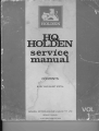
HOLDEN
servtce
rnarrual
CONTENTS
B O D YA N D S H E E TM E T A L
' SA L E SP T Y .L T D .
G E N E R A LM O T O R S - H O L D E N S
. S E R V I C ED I \ , I I S i O N
11I-ICI.DENPU B LICI,T IO N
MANUAL
SERVICE
VOLUME1
FOREWORD
Designed as a reference book for the competent
mechanic and a step by step procedure for the less
experienced,this Manual provides complete descriptive
information, maintenance and repair data on the HQ
Holden.
To use the index, bend the manual back to expose
the black section marks on the pages. Locate the
corresponding black section mark on the pages of the
sectionyou desire to find.
Where warranted, a more detailed table of contents
preceedseach section and an alphabetical index is included in the back of the manual.
Space is provided at the back of each section for
noting any additional service information received,subsequent to the publication of the Manual, through the
medium of ServiceBulletins.
The special tools illustrated are essential for the
efficient servicing of the HQ Holden and are available
throughmajor tool distributors.
The terms used in the description of operations are:
REMOVAL
meaning
AND INSTALLATION
simply to remove or take out a unit or parts of a unit,
and to put back the same unit or parts of unit.
DISASSEMBLY AND ASSEMBLY - means to
completely dismantle and put together a unit or parts.
of a unit after it has been removed from the vehicle.
REPLACE -.- rne&nSthe substitution of a new part
for a defective part.
All information, illustrations and specificationscontained in this manual are based on the latest product
information available at the time of publication approval. The right is reserved to make changes at any
time without notice.
Companion Volumes
N
L
SUSPENSION,BRAKES,
STEERINC. WHEELS
Part No M.37016
?
J
TRANSMISSIONSAND
REAR AXLES
Part No. M.37Ol7
A
-T
ENCINE AND GENERAL
INFORMATION
ELECTRICAL AND
AlR CONDTTIONING
R
J
Part No. M.37018
Part No. M.37019
CONTENTS
C E N E R AILN F O R M A T I O N
UNDERBODY
FRONTEND
REARQUARTER
REARCOMPARTMENT
ENDGATE
DOORS
SEATS
GIASS
STATIONARY
10
ROOF
11
METAL
SHEET
'12
EXTERIOR
ORNAMENTATION
13
RADIATOR
CRILLE
't4
BUMPERS
15
TOOLS
SPECIAL
15
ALPHABETICAL
INDEX
GENERAL MOTORS.HOLDEN'S SALES
PTY. LTD.
SERVICE DEPARTMENT
PARTNo. M.37015
COPYRIGHT REPRODUCTION
GENERAL MOTORS-HOLDEN'S SALES PTY. LTD.
IN WHOLE
OR IN PART PROHIBITED
VT|ITHOUT WRITTEN
APPROVAL
I
G E N E R A L I N F O R M A T I O N1 - 2
sEcrloNI
INDEX
Subiect
lntroduction
M o n u o lI n d e x . - . . - - - - - S e c l i o nI n d e x . . . . - - . - - - .
M o n u o lD e s c r iP t i o n
M o d e l l d e n t if i c o t i o n
B o d yl d e n t i f i c o t i o n
Bosic- Body Consfruction
B o d y S h e l l P o r t s R e p l o c e m e n t" " " " '
B o d y S e o l i n g- - - - - - - - - -
Poge
I - I
I - I
| - 2
I - 3
l-3
1-4
1-4
l-9
l-9
W o t e rL e o k D i o g n o s i so n d R e c t i f i c o t i o n" " " " - "
1-9
B o d y C e m e n t s ,S e o l e r so n d A d h e s i v eC o m p o u n d "s- - "
1-10
Body Lubricotion -..-.----.
M o i n t e n o n c e- A p p e o r o n c e" " " " " - " " "
C o r eo n d C l e o n i n go f I n t e r i o rT r i m " " " " "
L o c k C y l i n d e r s ,K e Y so n d L o c k s
S o f e t yG l o s s - - - - . - - G l o s sP o l i s h i n g - - - - - . - - . "
1 - ll
I - ll
r - 13
l-15
't-16
l-16
-!
I
G E N E R A L I N F O R M A T I O NI - 3
M A N U A LD E S C R I P T I O N
I ndex
Text
Page 1 - 1 contains a "Manual Index" which lists
the section number and subject title of each body
The first page in the major sections has
section.
an index to the subjects included in that section.
An alphabetical index covering the entire manual is
located in the back of the manual.
Unless otherwise specified, each service procedure
Procedures covering
covers all body styles.
specific styles are identified by the model numberor
style.
Model nanes with their corresponding
numbers are covered on this page under "Model
Identification" .
P o g e o n d F i g u r eN u m b e r s
All pase and fieue numbers consist of two sets of
The digits prcceding
digiti ieparatedby a dash.
The
the dash identify the main body area section.
digits following the dash represent the consecutive
page number or fi.gure number within the particular
body section.
ENGINE
Illusirotions
Where possible, illustrations are placed in close
proximity to the accompanying text and should be
used as part of the text.
M O D E LI D E N T I F I C A T I O N
( R i g hH
t o n dD r i v eO n l y )
DESCRIPTION
Hg8013s
v-8
Hg8o235
Belmont Station Sedan
HQ30169
HQ80269
Belmont Sedan
HQ80170
HQ80270
Belmont Panel Van
HQ80180
HQ80280
Belmont Coupe Utility
HQ80335
HQ8043s
Kingswood Station Sedan
HQ80337
HQ80437
Monaro Coupe
HgS0369
HQ80459
Kingswood Sedan
HQ80380
HQ8o48o
Kingswood Coupe Utility
HQ80837
Monaro GTS Coupe
HQ81135
HQS1235
Premier Station Sedan
HQB1169
HQ81269
Premier Sedan
HQ81137
HQ81237
Luxury Sports Coupe
HQ81469
Statesrnan De Ville Sedan
HQ81669
StatesmanSedan
HQ81837
Monaro GTS 350 Coupe
L-6
HQ8156e
G E N E R A L I N F O R M A T I O NI
- 4
BODY IDENTIFICATION
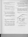
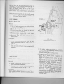
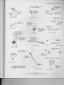
CompleteidentificationofeachbodyisprovidedbyabodyidentificationPlate,
side of the s6roud panel and
lii,r.'tr"t.a Fig. 1 - 1, attached to the upper left hand
plate must not be destroyed
This
is accessible when engine hood is ."it.a.
in its otiginal location'
re-installed
be
and if removed during ilody repairs, must
CEruENAI-MOTORS- HOLDENS PTY LTD.
BODY IDEN-r-tElgATlON---
-TH
T AEAN ESE NUMBERS
CE MU-S
d,NbET,T
coRRES-P
MODEL
HQ 8036e
TRIM
PAfNT
TOP
- 11E
11e8
568- 12203
568- 13134
BODY No. No 1-A
,/,-\
(O
MADE IN AUSTRALIA
FlG. l-l
B O D Y I D E N T I F I C A T I O NP L A T E
I rtm
Model
and
The model number is a combination of letters
stYle.
and
model
body
the
nurnbers identifYing
colour
The trim numbers represent the interior paint
and trim combination.
Point
The paint numbers represent the exterror.paint mat'
erial and colour identification of the basic or lower
colout.
Body
The body number is a numerical teference followed
by a sufhx letter which denotes plant at which body
- Adelaide, B - Brisbane'
*"s rn*trf..tured; i.e. A
- New Zealand'
M - Melboume, S - Sydney and NZ
Top
The top numbers represent the exteriot paint material
rrrd cjoru identification of the roof or upper section
of the body when it differs ftom the basic colour'
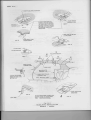
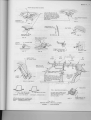
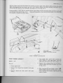
BASIC BODY CONSTRUCTION
The independent
.HQ' Series bodies are of unitised consttuction.
The Holden
front end sheet
for
attachment
ptovides
front end chassis partial frame, which
sides of underboth
along
mounted
'Lbb"t
etc','=
metal, front suspen"iorr,
",,gi"t,
I
d
e
n
t
i
f
i
c
a
t
i
o
nofmajorbody
l
Z
)
'
bodytorearof frontdooroit"lt'g=(seeFig'
andsheetmetalassembli.""r"illustratedinFigs'1-3'l-4and1-5'
S i n c e i n d i v i d u a l b o d y a n d u n d e r b o d y s t e e l c o m p o n e n t s c o n t r i b u t e d i r e c t l cortect
ytothe
as a whole' it is essential that
vehicle
the
of
,igidlty
strength
overall
"rra
sealing techniques be observed during body
alignment, welding, t;t p*ofi"g and
service and rePair oPerations'
-:-l---
G E N E R A L I N F O R M A T I O N1 ' - 5
r
\
,.' -/
G E N ER A L I N F O R M A T I O NI
ui
=
E.
L
J
.F
>-
d.
-lPugFtrlL
>-zzt-uzY.i
aoozoooogEUZeo;
coLu-uftLg;
so€N@
z
9
F
9
lI-
F
ZZ
ul<
<'l6O
l-ltJ
J6
-{
t
gru"t
,t=d
Fo
lut=o
!
06
o
o
dl
oo<oooooou
ooruoo<e(Yo<
u6e.v.0lulLLu@
FNOSnQN@OO
-,!
G E NE R A L I N F O R M A T I O N ' 1 " + ' 9
t!
=
e
lt
J
ju.
;^*<
F
;hiHa
;y22 <
dd3
-uz
{il11ilt
- o-*z'
az=a<6
=|[lo-zo,z
HLu.rusu
(YF(zFIIJF
uzt-zYz
oozouo
zeua.oe
:)rL(Jrr(tL
dGllddc;
F F F F F N
z
o
9Ee
Fo
ia
:e6
tJ;
-a<
,i[5
E= r
llj
I
UJE
a3
c!=
o
o
@
CD
vl
.<
2- a
l uu
;l < r
r-*
=Ee
o-6cI]
L>TL
oao
ooo
<ooz(Joaoooo
frJooo<aY<o')Z'llO
u.dj.Y. d.uv.FdtuIr(tLLao
FNo!n\ON@O\O-f{ot
G E N E R A . I TI N , F O R M A T I O NI - 8
U
=
N
L
.-
=
u>zYz
zou.ou
lcotL(YtL
o{o$N
z
9
F
u
IL
E,"
- 966*
l-ru
-<
|
,iFut
=U.lJ
L=uJ
pO
i!o
uJ=
I
oo
o
o
Co
fru.
Zu
<z
oorud(Y<oo<toE
6EU.tLtL04.g.0zcOtLc0lL
FNOSOAN@6OFN
-- 9
G E N E R A LI N F O R M A T I OIN
B o d y S h e l lP o r t s R e P l o c e m e n t
BodySeoling
When replacing or repairing a Part or sub-assembly,
cate must be taken to ensure that correct alignment
In
and strength of unit as a whole is maintained.
ftame
or
body
to
the
damage
major
some instances,
can be more effectively and economically repaired
be replacing a part or sub-assembly with a new one'
rather than repairing the damaged part.
After replacing body panels or assemblies, all underbody panel joins slrould be sealed with an underWhere it is necessaty to paint ovet
body sealer.
sealer, a neutral plastic sealer should be used.
Considerable attention is given to the sealing of
body shells during the process of manufacture to
For
ensure against the entry of water and dust.
various reasons, however, leaks may ultimately
Accidental damage for
develop in service.
If
example may disturb the sealing of a joint.
new body panels or members are required, various
manufacturing holes must be plugged, and spot
welded flanges coated with sealer.
Spot welding is used extensively for joining panels
together, particularly around the flanged edges of
dash panel, windshield and back window opening,
along edges of rocker panels and lower edge of rear
body.
When replacing a section that is normally attached
by this method and spot-welding equiprnent is not
available, or the location of parts prevents the use
of same, the part or assembly should be attached by
the welding method known as "plug welding", which
is as follows:
1. Remove the damaged part by cutting ttuough
the spot welds between the panels with a thinedged chisel or by drilling the spot welds'
2. Drill 3/16 in. dianeter holes in either the new
or mating part to conespond with the spacing
and location of the original spot welds. (Parts
to be drilled determined by accessibility for
following operations).
3. Clamp new part in position and gas or arc weld
the two parts together through each hole, finally
dressing off high spots on exPosed surfaces.
When replacing parts such as roof panels, rear
quarter or rocker panels; where a butt or overlap
weld is required, the join of the panels must
This
be formed below the normal contout.
join
and
the
over
loading
for
solder
allows
steel
sheet
of
reduction
possible
the
eliminates
thickness following the necessary buffing or
grinding of a normal welding operation
IMPORTANT, Following replacernent or repait
of body components, it is essential that proper
rust proofing techniques be observed.
.
Components should be tust-proofed whenever
body repair operations destroy or damage the
original rust-proofing.
W o t e rL e o k D i o g n o s i so n d R e c t i f i c o t i o n
As with all welded'type body shells, it is extren^ely
difficult to identify all the potential points where
The follovring information is
Ieaks mav occur.
therefore given as a general guide to the procedure
to be followed for diagnosing and rectifying leak
locations.
Diagnosis of leaks is complicated by the fact that
the appearance of water at one point can be caused
by seepage ttuough any one or more of rnanypossible
As an example of this indirect entry,
locations.
the cause of wet front floor coverings may be due
to water entering past the door weatherstrip, through
the door inner panel, between the windshield and
its giazing compound or through any one of the
joints in the floor panel, ventilator or dash panels,
therefore; point or points of water or dust enby
must be established before effective reseeling 6sn
be carded out.
Where autonatic type washit,g equipment is avail'
ab1e, the vehicle shoulci be subjected to a water
At
spray for a minimum period of four minutes.
the end of this period, the underbody should be
sprayed with a high pressure hose to simulate wet
weather conditions.
Alternatively, the watet test should be carried out,
using a medium pressure hose, giving a good delivery of water in the form of a spray to the upper
parts of the body; i.e., windshield, doors, drain
A high pressure hose should be
channels. etc.
used on the underbody in the mannerpreviously
described.
Having established the exact location of a leak,
the atea must be thoroughly cleaned and dried out.
The affected area should, if necessary, be deoxidized; primed and then sealed.
G E N E R A L I N F O R M A T I O NI - I O
B o d y C e m e n t s ,S e o l e r s o n d A d h e s i v e C o m p o u n d s
following list of body cements, sealers and
adhesive compounds, which are the same as those
used during manufacture of the vehicle, are available
7425347
Elastite caulking cornpound for sealing
sheet metal panel joins (2Yz Lb- tin)'
The
7425360 Underbody sealer for sealing underbody
panel joins and holes (2% lb. tin).
from NASCO.
PortNo.:
7425227 Mastic sealer for back window of Statesman models and rear quarter windows of
Station Sedans (1 lb. 3 oz. cylindrical
To be used with applicator
carton).
available from G.M. Skinner Pty. Ltd.,
42 Pine Street, ChiPPendale, N.S.W.
7425228 Plastic adhesive for cementing door
inner panel seals and shock absorber
mounting hole seals (1 Pint tin)'
7425230 P.V.C. adhesive for cementing P.V.C.
headlining
into
position
grey sealing
around tail iights.
742523r Prestik
CaulkingPackage.
2823265
Windshield Silicone
2823266
Rear window Silicone Caulking Package.
The successlul application of sealing and adhesive
compounds depends upon absolute cleanliness of
the areas to be treated, therefore; it is important
to remove all dust, water, grease or rust before
Inflammableadhesives
applyingthecompounds.
should be used in well ventilated
:*.:"tt"tts
(1 pint tin).
strip for sealing
7425233 Neutral plastic sealer for sealing body
joins where it is necessary to paint over
sealer (1 pint tin).
Adhesive compounds ate normally applied to both
surfaces to be loined, allowed to dry until tacky,
then pressed firmly together over the whole area to
If a coating of
provide maximum adhesion.
adhesive is allowed to &y, it can usually be reactivated by wiping with a diluent recommended for
the particular material being used.
For removing any excess sealet from paintwork or
backlight glasses, etc., use a cloth moistened with
white spirit.
7425330 Prestik black sealing strip for steering
colurnn opening cover (five strips per
unit).
I
NOTE: Petrol or paint thinner must not be used.
G E N E R A L l N F O R M A T I O NI - I I
The moving mechanical parts of the body which have metal to metal contact are
lubricated at assembly.
Operating conditions, whether nornal ot otherwise, determine the effective life of
of the lubricant and for this teason, lubrication in service is important.
Equally important is the type of lubricant to be used and for yout guidance we list
locarions and tecommended lubdcants.
result in
W A R N I N G : C a r e l e s s o r e x c e s s i u eo p p l i c a r i o n o f b o . d yl u b r i c a t t t s c a n
and
sparingtv
Lubricants
rc""tothi,g'
;-;;;;;i
p"iii ttit;i
;;i;;;;-,t
.u3i
at
ely'
e
di
imm
s
h
p
t
ain
m
o
ro
c
ati
n
app
li
tal'
o
d,
en
fini
,
u
f
"^o "' " "i
P o r r s R e o d i l yA c c e s s i b l e
P o r t sR e o d i l yA c c e s s i b l e
Where ptacticable, use Zinc Oxide Grease; otheF
wise use light oil.
Engine Hood Catch.
Engine Hood Lock.
Engine Hood Hinge.
Door Hinge and Hold'oPen CliPs.
Instrument Compartment Lid Hinge.
Rear Compartment Lid Hinge.
Rear Compadment Lid Lock Mechanism.
Rear Seat Hinges (Station Sedan).
Floor Filler Panel Hinge (Station Sedan).
End Gate Hinge Assembly.
End Gate Locking Mechanism.
Lowet End Gate Limit Arm.
Plenum Chambet Control.
Apply Powdered Graphite through Key Aperture
(do not oil).
Ignition Lock Cylinder.
Rear Compartment Lid Lock Cylinder.
Doot Lock Cylinder.
Instrument Panel Compartment Lock Cylinder.
End Gate Lock Cylinder.
End Gate Lock and Switch AssemblY.
U S E N A S C OS O L I D O I L
'Door
Lock Striker Bolt.
Door Lock Fork Bolt.
Insttument Compartment Lid Lock Tongue.
MAINTENANCE -
P o r t s C o n c e ol e d N e c e s si t o t i ng D i s o s s e m b l y
Where practicable, use Zinc Oxide Grease, other.
wise use light oil.
Door Window Regulatot.
Door Window Glass and Cams.
Door Lock Mechanism.
Door Lock Remote Control.
Rear Quarter Window Guides and Cams.
Front Seat Adjuster.
End Gate Regulatot.
End Gate Remote Conttol.
APPEARANCE
that it is kept
To presetve the original paint finish of the vehicle, it is essential
grime that
road
and
dirt
washing not only temoves
clean by frequent *.shirrg.
grime, in
such
settles on the vehicle, but also dilutes acids which accomPany
areas which often
particular; salt from air or sea sPray encouuteted in coastal
Tree sap, road tar, exctetion ftom insects and
L..oln. trapped in crevices.
chemicals and other foreign matter that
hannful
contain
indusbial fall out often
These should be removed
the cat'
of
finish
paint
may pennanently damage the
agent'
temovaf
without delay, using an effective
G E N E R A LI N F O R M A T I OIN- I 2
l . R e g u l o rW o s h i n g
2. Polishing
If the vehicle is in continuous use, it should be
washed at least once a week with either cold or
warm water (preferably running water), using clean
chamois leathers, sponges or rags free from dirt or
grit likely to scratch the paint finish.
It is good
practice to first hose the vehicle to remove as much
of the grit and grime as possible before swabbing
the surface.
When hosing, it is important to hose
under the front fenders, rear wheelhouses and along
any underbody ledges to remove any dirt or mud
which can collect in these areas and can, if neglected, cause corrosion.
Over a period of time, foreign matte( (road scum)
may build up on the paint surface to the detriment
In these circrrnstances
of its overall appearance.
the use of Delco General Cleaner and Polish is
recommended.
Do not attempt to polish without first washing the
vehicle to temove existing loose gdt or surface dirt.
Delco General Cleaner and Polish should be applied
with a damp,clean, soft cloth, stockingnet or cheese
cloth, allowed to dry and the final clean up obtained
by polishing with a dry, soft cloth.
Do not wash the vehicle under bright sunlight when
high temperatures are being experienced', as this
will result in a streaky, watermarked finish.
Inspection
V i n y l R o o fC o v e r
The cover should be washed frequently with neutral
soap suds, lukewarm water and a soft bristle brush.
Rinse cover with fresh water until all traces of soap
are removed.
Tor
Tar stains can be removed with Holt's Tar Remover
or Shellite, providing the stain is not allowed to
remain on the paint finish for an indefinite period.
P e t r oI
Regular inspection of the vehicle should be made
for scratch marks, cracks or damaged areas, all of
which could develop rust and thus affect paint finish.
Any deep scratches, cracks or breakdown in the
finish should be repaired without delay.
Care should be taken to ensure that any rusting is
counteracted immediately, otherwise rust "cteep"
This
will extend beyond the damaged area.
applies particularly in sub-tropical areas or coastal
districts, where the moist or salt laden atmosphere
accelerates rusting if it is allowed to develop
The paint finish of the vehicle
through neglect.
gives a very high degree of protection against the
weather, but it should be realised that wear and
deterioration occur when the car is exposed to
elements for prolonged periods.
Wash off with water immediately.
CAUTION' Prolonged contact of petrol with paint
finish will tesult in permanent staining
of the paint.
The vehicle therefore should be garaged whenever
possible.
I n s e c tS p o t s
P r o t e c t i o no f B r i g h tM e t o l P o r t s
Insect spots on the paint finished parts of the vehicle can be easily washed off by using a solution
containing two quarts of water in which half a pound
of baking soda (Bicarbonate of Soda) has been dissolved. trlush the washed parts with clean water.
The destructive forces of salt air and corrosive
atmosphere can be eliminated if bright metal parts
are thoroughly washed regularly in the same manner
as the paint finish of the vehicle.
After washing and drying, park the vehicle in
shaded area.
NOTE: Never scour or
use abrasive polishes.
G E N E R A L I N F O R M A T I O N - I- . I , 3
CARE AND CLEANING OF INTERIOR TRIM
Loose dust and dirt particles that accumulate on the surface of interior trims should
This can be
be removedevery few weeks; more often with constant hard driving.
soft
brush'
or
cleaner
vacuum
teafily achieved, using a
IMpORTANT, Before attempting to remove spots and stains from trim rnaterial,
it is necessary to determine as accurately as possible:
1.
The nature and age of the stain.
2.
The eff'ect of the stain removal agent upon the colout, structure and
general appearance of the trim material.
after
It is essential that stains be removed from trin: rnaterial as soon as possible
indefinitely,
the
material
on
remain
to
allowed
are
they
If
they have been made.
they can become oxidised and removal is difficult, if not impossible'
D e s c r i p i i o no n d C l e o n i n gM e t h o d s
In general, vinyl material is used fot seating, headThe grades of vinyl
lining and auxiliary trimming.
used vary with the particular wear required of them.
The seat insert on some production options are manufactured with synthetic (nylon, rayon) fibres.
CAUTION, When cleaning such fabdcs, do not use
a whisk brush since damage to the fine
threads mav result.
The above cleaning instructions
rubber floor covering.
also apply to the
IMPORTANT, Whete stubborn stains on trim mat'
erial fail to respond to the above methods, a
light application of Delco General Upholstery
Cleaner or white spirits with a soft cloth will
invariably Ptove satisfactorY.
NOTE: Do not use cleaner or white spirits excessively.
C l e o n i n gC o r p e t s
Care of P.V.C, material is a telatively simple but
The surface should be wiped
important matter.
over occasionally with a dry cloth and if dirt, should
accumulate, the following cleaning instructions
should be used:
1. Using lukewatm water and neutral soap, work
.rp . *otp lather on a Piece of cheese cloth
and applY to the material.
A soft bdstled brush may be used to aclvantage
to remove stubbotn stains or dirt embedded in
the grain of the material.
2. The operation should be repeated, using only
a damp cloth a:rd no soaP.
3. The trim should then be wiPed dry with a soft
cloth
In many
Thoroughly brush or vacuum the carpet.
cleaning'
further
no
require
may
carpet
instances the
If the caqpet is excessively soiled, remove carpet
from vehicle, thorougtily vacuum it to remove loose
dirt; then, with a foaming type carpet cleaner, clean
After
apptoximately one square foot at a time'
cleaner
the
of
much
as
.t". is cleaned, remove
"".h
pile.
If oil or grease spots are still present on the calpet,
they nay be removed by using a volatile cleaner'
S p e c i f i cS t o i n sf r o mT r i m
Removing
For certain specific stains, special treatment is
It must be expected, particularly
necessary.
where water treatment is specified, that discolouration and material disturbance may occur.
G E N E R A LI N F O R M A T I OIN- I 4
B o t f e r yA c i d s
Sweets
Apply ordinary household ammonia with a brush or
cloth to the affected atea, saturating it thorougtrly.
Permit the arnmoniato remain on the spot for apProximately one minute to neutralize the acid, then rinse
the spot by rubbing with a clean cloth saturated
with cold water.
Sweet stains other than sweets containing chocolate
can be removed by rubbing the affected area with a
If the stain is
cloth soaked with very hot water.
lightly (after
the
area
rub
removed,
completely
not
cleaner.
volatile
a
with
cloth
wet
a
drying) with
Howevet, no type of treatment will repair damage to
matedal resulting from the action of the acids, particularly after the spot has dried.
Blood
Rub the stain with a clean cloth saturated with cold
Only use clean
water turtil the stain is rernoved.
stain.
rubbing
the
portions of cloth for
This treatment should remove all of the stain. If it
does not,apply a small mount of household ammonia
After a lapse
to the stain with a cloth rr brush.
stain with
the
to
rub
continue
of about one minute,
clean
water.
a clean cloth dipped in
If the stain remains after the use of water and
ammonia, a thick Paste of corn starch and cold
Allow the Paste to remain
water nay be applied.
until it has dried and absorbed the stain, then pick
Brush the surface to remove
off the drv starch.
For bad stains,
starch particles that remarn.
several applications of starch paste may be nec'
essaty.
CAUTION: Do not use hot water ot soap and water
on blood stains as this will set the
stain, thereby making its removal practically impossible.
S w e e t so n d C h o c o l o t e
Sweet stains resulting from cteam and ftuit-filled
clpcolates can be removed more easily by rubbing
with a cloth soaked in lukewarm soaPsuds (mild
neutral soap) and scraping, while wet, with a dull
This treatment is followed with a rinsing
knife.
the spot with a cloth dipped in cold
rubbing
by
water.
Stains resulting from chocolate can be removed by
rubbing the stain with a cloth wet with lukewann
After the spot is dry, rub it lightly with
water.
in a volatile cleaner.
dipped
a cloth
C h e w i n gG u m
Harden the gum with an ice cube and scrape off
[f gum cannot be removed
with a dull knife.
completely by this method, moisten it with a volatile
cleaner and work it from the matedal with a dull
knife, while gum is still moist.
F r u i t S t o i n s L, i q u o r ,W i n e
Practically all fruit stains can be removed by treatWet the stain well by
ment with very hot water.
with a clean cloth.
spot
the
to
applying hot water
off the material
present,
if
pulp,
Scrape all excess
with a cloth
vigorously
rub
then
with a dull knife;
is
very old or
stain
If
the
with very hot water.
hot water
vety
pour
to
deep, it may be necessary
with
tteatnent
this
following
directly on the spot,
hot
of
application
Direct
scraping and rubbing.
for
general
recommended
water to matedal is not
use, since discoloutation usually results.
If the above treatments do not temove the stain,
allow material to dry thorougtrly; then rub lightty
with a clean cloth dipped in a volatile cleanet.
This is the only futther treatment recommended.
Soap and watet are not tecommended, since they will
probably set the stain and cause a permanent discolouration.
G r e o s eo n dO i l
As much grease as possible should be removed by
scraping with a duIl knife.
Grease and oil stains may be removed by rubbing
lightty with a clean cloth saturated in a volatile
cleaner.
Be sure all motions are towards the
centre of the stained area, to decrease the possibility of spreading the stain.
G E N E R A LI N F O R M A T I OIN- : I 5
lce Creom
Tor
The same procedure is recommended for the removal
of ice cream stains as that used for removing fruit
If the stain is persistant, rub the spot
stains.
with a cloth wet with warrn soap suds (mild neuual
Use a clean cloth to apply a cold water
soap).
When dry, rub area lightly with
rinse to the area.
a cloth wet with a volatile cleaner.
Moisten the spot slightly with a volatile cleanet,
then remove as niuch of the tar as possible with a
Follow this operation by rubbing the
dull knife.
spot lightly with a cloth wet with the cleaner until
the stain is removed.
N ou s e o
Sponge with a clean cloth dipped in clear cold water.
After m,rstof the stain has been removed in this way,
wash lightly with soap (mild neutral), using a clean
cloth and lukewarm water, then rub with another
If any of the
clean cloth dipped in cold water.
stain remains after this treatment, gently rub with a
clean cloth moistened with a volatile cleaner.
S h o eP o l i s ho n d D r e s s i n q s
Urine
Sponge the stain with a clean cloth saturated with
lukewarm soapsuds (mild neutral soaP), then rinse
well by rubbing the stain with a clean cloth dipped
Saturate a clean cloth with a solin cold water.
household
ammonia and five parts
ution of one part
cloth
to the stain and allow
Apply the
water.
the solution to remain on the affected area for one
minute; then rinse by rubbing with a clean cloth and
cold water.
For shoe dressings containing starch or dextrine
or some water soluble vehicle, sponge with a clean
cloth dipped in cleat cold water.
L i ps t i c k
Paste ot wax-type shoe polishes may require using
Rub the stain gently with a
a volatile cleaner.
cloth wet with a volatile cleaner until the polish is
removed. Use a clean portion of the cloth for each
rubbing operation, and rub the stained area from outside to centre.
The compositions ofdifferentbrands of lipstick vary,
making the stains very difficult to remove. In sorne
instances, a volatile cleaner may remove the stain.
If some stain remains after repeated application of
volatile cleaner, further treatment is not recommended as this may damage the material.
LOCK CYLINDERS,KEYS AND LOCKS
'HQ'
A11
models are equipped with new, five bitting depths lock cylindets.
Two,
non interchangeable keyways are used in these lock cylinders.
A square headed
key operates the primary keyway of ignition, doors and on station sedans; endgate
lock cylinders.
A.r oval headed key operates the secondary keyway of instrument panel compartment door and rear compartment lid lock cylinders.
Key code
numbers of the ignition and instrument panel compartment lid locks are stamped on
the side of the lock cvlinders.
Key identification
keys.
code numbers are stamped on the KNOCK-OUT
section of the
New "fork type" door locks with "bolt type" lock strikers incorporating a free
wheel action are also featured on these models.
G E N E R A L I N F O R M A T I O NI - I 6
SAFETY GLASS
With the exception of the optional laminated safety glass windshield, all glass
This type of
surrounding the vehicles occupants is armour plate safety glass.
glass, when struck by a stone throyvnup by a passing vehicle, can become opaque
Toughened safety glass windshields incorporate an
in a spider web pattern.
This zone covets an
additionat safety feature in the form of a rnodified zone.
oval area approximately 17.5" wide by 7" deep, and is located at eye level directly
Should the glass shatter, larger particles of glass in the
in front of the driver.
modified zone allow adequate vision, although vision surrounding the zone can be
completely obscure due to smaller particles of glass in the remainder of the windshield.
A11 safety glass in the vehicle is insulated against shock, either by adhesive
caulking compound, rubber retainers or rubber and felt glass run channels.
NOTE. It is possible for the safety glass to be struck by an object thrown up by a
passing vehicle, without the owner being aware and without the immediate
The actual shattedng of the glass can occur
shattering of the glass.
some time after the impact and is due to the effect of the impact onto the
stresses of the glass, together with variations in temperature. Our experience is that safety glass shattering from causes other than being struck
by an object is remote.
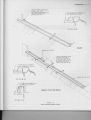
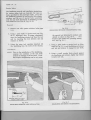
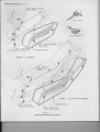
M I N O R G L A S SS C R A T C H EoSn d A B R A S I O NR E M O V A L
De s c r p
i tion
Minor glass scratches and abrasions can be effectively removed or substantially
reduced by utilizing a felt padded low speed rotary polisher in accordance with
the following procedute and precautions.
Removal of minor scratches and abrasions ftom glass is an operation that requires
reasonable care. When removing minor windshield glass scratches and abrasions,
double vision must be prevented from developing in areas that will distort the
Glass distortion is most likely to result when attempting to
drivers vision.
remove deep scratches.
Avoid using excessive plessule when using the rotary polisher as this may ovelThe polisher must never be held in any one spot for longer
heat the glass.
If the glass becom,:s hot to touch, allow the glass
than 40 seconds at a time.
Avoid cooling with cold water
to air cool prior to proceeding with the operation.
as this may crack the glass.
G E N E R A LI N F O R M A T I O N l ' - i f ,
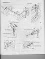
The following equipment is tecommended for minor
glass and abrasion temoval:
(a) A low speed (600-1300R.P.M.) rotary polisher.
(b) A wool felt rotary type polishing pad approximately 3" in diameter and 2" thick.
(c) Powdered Ceric Oxide mixed with water as
an abrasive compound.
(d) A wide mouth container to hold the compound.
G l os s S c r o t c ho n d A b r o si o n R e m o v o lP r o c e d u r e
1. Place a sufficient amount of powdered Ceric
Oxide in the bottom of the containet and mix
in sufficient water to obtain a creamv consistency.
NOTE: If the compound is too thick, it cakes on
the felt pad too quickly and if too thin, the
operation time is extended.
5. Dip the pad into the mixture at 15 second intervals to ensure that the pad and glass are
always wet during the operation.
A dry pad
causes excessive heat to develop.
NOTE: Never fully submerge or allow pad to remain
in compound as this may loosen the bond
between pad and metal plate.
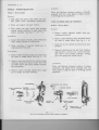
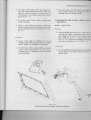
6. Using a moderate but steady pressure, hold
the pad flat against the scratched area of the
glass and using a feathedng out motion to
prevent the possibility of a "bulls-eye", remove
the scratch or abrasion, as illustrated in Fig.
1-6
7. Clean
off
compound and remove ptotective
co vedng.
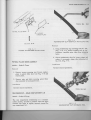
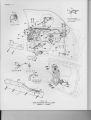
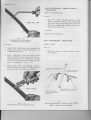
F E A T HE R I N G . O U T
MOTION
GUIDELINES
2 . Place a protective cover over paintwork adjacent to area where the operation is to be
cartied out.
3 . Agitate the compound occasionally to maintain
a creamy consistency. Powdered Ceric Oxide
is insoluble in water and tends to separate.
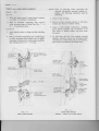
4 . Draw a circle around the scratches or abrasions
on the inside of the glass, using a marking
crayon.
Also draw lines directly behind
scratches or abrations to assist in locating
the rotary polisher, as illustrated in Fig. 1-6.
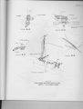
H O L D P A D F L A T A G A I N S TG L A S S
FlG. l-6
M I R R O RG L A S SS C R A T C HR E M O V A L
Q E N E R A I .I N F O R M A T I O N I - I 8
BULLETIN REFERENCES
U N D E R B O D 2Y - ' I
sEcTroN2
INDEX
Subiect
Poge
LlnderbodyAlignment
C o v e r i n g- F r o n t F l o o r - - - - . - . - - -
2 -1
2 - 5
Seot Seporotor----------------
2- 6
2 - 6
Console-TronsmissionControl
T o n n e o uF l o o r - F r o n t - - - - . - - - - - -
2-6
2 - 6
C o v e r i n g- R e q r F l o o r - - - - - - - - -
.-
--
C o v e r i n g- T o n n e o uF l o o r - F r o n t o r R e o r 2 - 7
C o v e r i n g- T o n n e o uF l o o r S i d e S il l - - . - - - - - - -2 - I
2 - g
F i ff e r P o n e l
Covering-FillerPonel
2-g
Sill Plote
2-B
UNDERBODY
ALIGNMENT
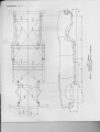
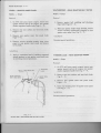
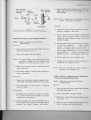
Correct undetbody alignment is essential, as any misalignment of the underbody can affect
suspension, fitment of doots, engine hood, rear compartnent lid or end gate.
The underbody should therefote be aligned to within l/16 i^. of dimensions specified in
Figs. 2-1, 2-2 and 2-3.
These dimensions should be accutately checked with a
tram gauge consisting of a parallel bar or tod, fitted with two adjustable trammels, capable
of gauging all underbody dimensions specified.
In preparing an underbody alignment check, place vehicle.on
weight of the.body supported at wheel locations.
a level surface with the
UNDERBODY
z
=
ut
F
F
0
ei
;l!
=(J
2x
fi
lri
I
J
ul
o
o
=
N,
s
I
e
sb
N
lr)
--------:.1
UNDER'BOD$IP(J{TJ
I
b
$
b
\l
z<
oo
9a
1E5
l - -
OF
i>s
9^o5
r!X
I
E_1
llJ 9.1
2e
J=
o
- \i.
U N D ER B O D Y
2z
a=
-frfr
"i
=i
:>i^
(90
|
oE;
EC
f
U N D E R B o D Y ':a 0 t t B
ATTACH WITH
PVC ADHESIVE
S E C T T OA
N- A
8 r 4 0 0o N L Y
S E C T I O NA - A
S E C T I O NB - B
^--^"'-
--l'-"
D A S HI N S U L A T O R
B E N Dr A B T O R E T A I NT R l i , l
s E c r r o cN- c
T R I M P A N E L S H R O U DL O W E R
C A R P E T M U S TF I T
TUNNELNEATLY
RETAIN FLOOR COVERING
U N D E RT R I M
S E A L W I T HC A U L K I N G
COMPOUND
lll'it
F R O N T F L O O RC O V E R I N G
FASTENER
D. D
SECTION
2 PLACES
R E A RF L O O RF I L L E RM A T
F I T T E DW I T HB U C K E T
MODELS
TEPARATOR
S E A T SW I T H O U S
=1N.
R E A RF L O O RM A TC O V E R I N G
S E C T I O NE - E
F I T T E DW I T H4 S P E E D
MODELS
TRANSMISSION
F L O O RC O N T R O L
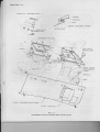
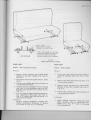
FIG-2 - I
F L O O R C O V E R I N GI N S T A L L A T I O N
C O V E R I N G- F R O N T F L O O R
M o d e l s- A l l
4. Loosen sill
Rernovol
1. Position
3. Where fitted, remove seat separatot ot transmission conttol console (tefer page 2 - 6\.
plate attaching screws.
5. Remove ftont floor covedng.
ftont sea(s) fully re€rwEud.
l n s t ol l o t i o n
2. Remove stuoud lower tdm panels (refet PqSe
3-1).
Revetse temoval operations (see Fig. 2 - 4).
U N D ER B O D Y
C O V E R I N G- R E A R F L O O R
NO N T R O L
C O N S O L E- T R A N S M I S S I OC
M o d e l s- A l l
M o d e l s- G T S C o u p e& O p t i o n o l
Removol
Removo
I
2. Remove handbrake cover.
1. Raise lid of vanity box section of console and
ease away carpet, which is attached to base of
console with neoprene cement.
3. Remove front seat belt to tunnel attaching bolts.
2. Removegear lever control knob (see Fig. 2-5).
4. Where fitted, remove seat seParator or trans'
mission control console (refer this page).
3. Remove ashttay assembly.
1. Position front sea(s) fully forward.
5. Remove tear seat cushion ftame bracket to rear
floor crossbar attaching screws (see View D,
Fis. 8 - 6).
6. Loosen sill plate attaching screws.
7. Remove rear floor covering.
4. Rernove screws securing rear end of console
and ttansmission cover facia to console.
5. On vehicles fitted with automatic transmission,
disconnect transmission indicator illuminative
harness then remove facia.
6. Remove screws securing front end of, console
to transmission tunnel then remove console.
lnstollotion
lnstollotion
Apply caulking compound around front seat belt bolt
to tunnel attaching holes prior to reversing removal
operations (see Fig. 2 - 4),
Apply caulking compound around console to transmission tunnel attaching holes prior to reversing
removal operations.
SEAT SEPARATOR
M o d e l s- C o u p e& O p r i o n o l
T O N N E A UF L O O R- F R O N T
R e m o v Io
M o d e l s- S t o t i o nS e d o n
1. Raise lid of seat separator and ease away
carpet, which is attached to base of seat
separator with neoprene cement.
R em o v oI
1. Lower tear seat squab.
2. Remove ashtray assembly from seat separator.
2. Remove spare wheel cover.
3. Remove screws securing base of seat separator
to transmission tunnel then remove seParator.
3. Remove screws securing outer edges of tonneau
floor to underbody assembly.
lnstollotion
Apply caulking compound around seat separator
to transmission tunnel attaching holes priot to reversing removal operations.
4. Lift out front tonneau floor.
I n s t oI l o t io n
Reverse temoval operations.
UNDERBODY 2 - 7
p
iirlitiir:;
O
itr
ii:riii,
::+
.' ff
FlG.2-5
T R A N S MSI S I O NC O N T R O LC O N S O L E
M O D E L- G T S C O U P E
F L O O R- F R O N To r R E A R
C O V E R I N -G T O N N E A U
M o d e l s- S t o t i o nS e d o ne x c . B e l m o n t
lnstollotion
Removol
1. Remove tonneau floor
structions).
5. Remove or snooth down any hardened adhesive
from edges of tonneau floor and covering.
(refer pteceding in-
1. Apply an even coat of vinyl trim adhesive to
edges of tonneau floor and to inside, outer
edges of coveting.
2 . Remove wear strips.
3 . Remove staples securing edges of covering to
2. Apply covering to tonneau floor, ensuring that
covering is wrinkle free.
base of tonneau floor.
4 . Carefully temove covering, the edges of which
are attached to the tonneau floot
trim adhesive.
3. Staple edges of covering to base of tonneau
floor.
with vinyl
4. Install tonneau floor.
UNDERBODY 2 - 8
I
I
I
C O V E R I N_G T O N N E A U
F L O O RS I D ES I L L
C O V E R I N-G F I L L E RP A N E L
M o d e l s- S t o t i o nS e d o ne x c . B e l m o n t
M o d e l s - S t o t i o nS e d o ne x c . B e l m o n t
Removo
I
Removo
I
1. Lowet rear seat squab.
l.
2. Remove rear quarter trim panels (see page
_ 1).
,4
2. Remove wear strips.
Remove filler panel (refer preceding instructions).
I
I
3 . Rem,cverear tonneau floor.
3. Remove cover strips surrounding outer edge of
filler panel.
4 . Remove screws securing front and rear inner
edge of covering to rear side floor.
Carefully remove covering, which is attached
to the side sill with vinyl trim adhesive.
4. Carefully remove covering, which is attached
to the filler panel with vinyl trim adhesive.
5. Remove or smooth down any hardened adhesive
from panel or covering.
6. Remove or smooth down any hatdened adhesive
from the side siil or covgring.
Instollotion
I n s t o l l oi fo n
1. Spray or brush on an even coat of vinyl tdm
adhesive to side sill and inside of covering.
2. Apply covedng to side sill,
covering is wrinkle free.
ensuring that
3. Install screws to front and rear inner edge of
covering.
4. Install rear tonneau floor and rear quarter trim
panels (refer page 4 - 1).
1. Spray or brush on an even coat of vinyl trim
adhesive to top of filler panel and to inside of
covering.
2. Apply covering to panel, ensuring that edges of
covering fit flush with panel and that covering
is wrinkle free.
3. Install filler panel (refer preceding instructionsl
SILL PLATE
M o d e l s- A l l
Re m o v oI
F I L L E RP A N E L
M o d e l s - S t a t i o nS e d o n
R e m o v oI
1. Lower rear seat squab.
2. Remove screws securing filler panel hinge to
rear floor riser panel.
3. Remove filler panel
Instollotion
Reverse removal operations.
1. Remove screws securing park brake cover to
brake lever base.
2. Remove screws securing sill plate to rocker
panel (see Fig. 2 - 6) then remove sill plate.
NOT E: The removal of the fiont sill plate on sedans
and station sedans necessitates the removal
of the foremost rear sill plate to rocker
panel attaching screw (see Section A_A.
Fis. 2 - 6).
Instollotion
Reverse removal operations.
UNDERBODY 2 - 9
D O O RO P E N I N GP I N C H W E L D
F I N I S HL A C E T O B E
R E T A I N E DU N D E RE A C H E N D
OF SILL PLATE FORA
D I S T A N C EO F . 5 0
F L O O R M A T SO R C A R P E T S
F I T U N D E RS I L L P L A T E S
S E C T I O NA - A
.,--1/
//
C OU P E
R E A RS I L L P L A T E
F R O N TA N D R E A R D O O R
O P E N I N GP I N C H W E L D
F I N I S H I N GL A C E T O B E
R E T A I N E DU N D E RE A C H
E N DO F S I L L P L A T E S
F O R A D I S T A N C EO F ' 5 0
T O F I T U N D E RS I L L P L A T E S
.<
S E C T I O NB - B
M A T SO R C A R P E T ST O
D E RS I L L P L A T E S
S E D A N& S T A T I O NS E D A N
A- A
SECTION
FlG,2 - 6
SILL PLATE INSTALLATION
F R O N TS I L L P L A T E
UNDERBODY 2 - IO
NOTES AND BULLETIN REFERENCES
F R O N T E N D3 - I
sEcfloN 3
INDEX
S ub le c t
V e n t il o t i o n- D e s c r i p t i o n. . . . . . . . . . . - . . . .
A i r D u c t A s s e m b l y- P l e n u mC h o m b e r
U p p e rL e v e l A i r O u t l e t- I n s t r u m e nPt o n e l - . . . - . . . .
G r i l l e - S h r o u dV e n t iI ot o r
'P ^
- Y^ -^
3-2
')A
3-4
H o o d L o c i n g - - S h r o u dL e d g e
C o m p o r t m e n&t D o o r - I n s t r u m e n P
t onel
L o c k C y l i n d e r& H o u s i n g- I n s t r u m e nPf o n e lC o m p o r t m e nDto o r
L o c k S t r i k e r- | n s t r u m e n tP o n eI C o m o o r t m e nDt o o r . . - . . . . . - . - .--. . . . . -
1A
T r i m P q n e l- S h r o u dL o w e r
P o d - l n s t r u m e nPt o n e l
1A
F o c i o - I n s t r u m e nPt o n e l . . . . . - . . . C o n t r o lC o b l e- B o d y V e n t il o t i o n - . - . . . - . . .
3-6
't7
C l o s i n gP o n e l - I n s t r u m e nFt o c i o . . . - . - - . N o m e o l o t e- l n s t r u m e nFt o c i o . . . - . . . . - .
20
H e o f e r& D i s t r i b u t i o nD u c t A s s e m b l y
M o t o r& l m p e l l o rA s s e m b l y- H e o t e r
3-9
'lo
J-Y
C o n t r o l C o b l e - H e o t o n d , / o rD e m i s f
- Windshield
G o r n i s hM o u l d i n g
J -
Windshield
r ssy.- Description
W i p e rM o t o r ,L i n k o g e& W o s h e A
d i p e r& W o s h e r
M o t o r& P u m pA s s e m b l y W i n d s h i e l W
3 - 12
3 - 12
P i v o t& L i n k A s s e m b l i e-s W i n d s h i e lW
d iper
B l o d eA s s e m b l y- W i n d s h i e lW
d iper
3 - 15
R o d A s s e m b l y- W i n d s h i e l d
Wiper
r ontrol
S w i t c hA s s e m b l y W i n d s h i e l d
W i p e r& W o s h e C
3-12
tz
3 - 15
3 - 15
3 - 15
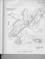
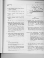
F R O N TE N D
BODY,,FLOW,
THROUGH,,
VENTILATION
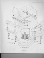
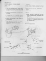
Description
The new ventilation and heating system on all
hot or cold air to "flow through" the body.
'HQ'
models allows fresh or mixed
Fresh air entering the shroud ventilation grille forward of the windshield, passes
into a full width plenum chamber, from where it is directed to the upper and lower
Finger
air outlets located both on and under both ends of the inshument panel.
grip controls marked "VENT" located on each side cf the instrument cluster,
operate flaps within the R & LH air ducts, directing air down on the floor, through
With the "VENT" control pulled fully out, maximum lower level
these ducts.
air flow is attained, with reduced air flow through the upper level outlets.
With
control fully closed, lowet level air flow is shut off and maximum
the "VENT"
Serrated wheels on eithet end of the rotable
upper level air flow is possible.
Balanced
vanes are used to direct or shut off air flow ftom the upper air outlets.
air flow through upper and lowet level air outlets can be achieved by intermediate
setting of the lower vent controls and by opening the upper level air outlet directional vanes.
A heat/demist control incorporating an air induction fan switch is attached to the
RH side of the instrument carder.
Fresh air entering the plenum chamber is
drawn into the heater (air mix unit) via a branch from the LH air duct. This forced
air has alternative routing, either through or by passing the heater core. Control
is achieved by selecting the control knob setting on the RH side of the instrume;rt
cartier, proportioning the hot and cold air mixture, thus achieving the desired discharge.temperature.
This ait flow can be directed to foot, seat level or demist
outlets'in varying proportions or completely shut off, dependent on control knob
setting.
Bowden cables attached to the control knobs operate air deflector doors
within the heater unit.
With all windows in the vehicle closed, air flowing tlnough the body, exhausts
through pressure relief valves fitted to the rear body lock pillars (see Fig. 3 - 1).
This partibl pressurization of the body reduces wind noise and dust entry into the
An optional air conditioning unit available on all 'HQ' models except
vehicle.
GTS l;0 manual, incorporates a heater core.
A four speed air induction fan
attached to the air conditioner induces hot, cold or mixed air to be ducted into the
body via air outlets located centrally and on both ends of the instrument panel,
through the windshield demist ducts or onto the floor, dependent on control knob
setting.
F R O N T E N D3 - 3
69 STYLES
35 STYLES
/
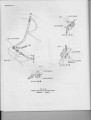
V I E WB
37 STYLES
FrG.3- l
B O D Y" F L O WT H R O U G HV' 'E N T I L A T I O N
FRONTEND3-4
A I R D U C TA S S E M B L-Y P L E N U MC H A M B E R
Instollofion
M o d e l s- A l l
Reverse removal operations, ensuring that seal of
air duct assembly to plenum chamber is water tight.
Removo
I
1. From under instrument panel, remove screws
securing end of ventilator control cable casing
to plenum chamber air duct (see View B, Fig.
U P P E RL E V E L A I R O U T L E T - I N S T R U M E N T
PANEL
3-2).
Models -
2. Disengage end of ventilator door control cable
to air duct.
R e m o v oI
1. When removing LH upper level air outlet,
remove instrument panel compartment (refer
page 3 - 5).
3. Disengage upper level air outlet duct by compressing end of outlet duct attached to plenum
chamber air duct (see Section A-A, Fig. 3 - 2).
2. From behind instrument panel, compress top
and bottom of upper level air outlet(see Section
C-C, Fig. 3 - 2) withdrawing outletinto body
from insttument panel.
4. Remove screws secruing air duct assembly to
plenum chamber.
5. Ease
before
tained
Fig. 3
inner side of assembly down slightly
disengaging outer side, which is reby two plastic lugs (see Section B-8,
- 2).
All
lnstollotion
Reverse removal operations.
I
I
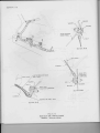
INSTRUMENT
P A N E LP A D
U P P E RL E V E L A I R
O U T L E TD U C T
SECTION
B-B
S E C T I O NC - C
, A.iti,
s r c r r o NA - A
i'\
\
plrNuM cHAMBER
A r RD U c r
V E N TI L A T O R
C O N T R O L& C A B L
VIEWA
VIEWB
Ftc3-2
V E N T I L A T OD
RU C T I N G
& CONTROLS
F R O N TE N D 3 - ' 5
G R I L L E- S H R O U V
DE N T I L A T O R
2. Remove screws securing R & LH hood lacing
retainers to shroud upper panel, then remove
tetainers and lacing.
M o d e l s- A l l
R e m o v oI
lnstollotion
1. Raise engine hood.
2. Remove sctews securing ventilator grille
shroud upper panel, then remove gdlle.
Reverse removal operations.
to
lnstollofion
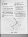
COMPARTMENT
& D O O R- I N S T R U M E N TP A N E L
Reverse removal operations.
Models R e m o v oI
H O O DL A C I N G . S H R O U DL E D G E
M o d e l s-
All
1. Remove
screws secudng instrument panel
compartment hinges to door (see Section A-A,
Fig. 3 - 3) then remove door.
All
I
Removo
1. With engine hood raised, remove scr€wS s€curing front of stnoud ventilator gdlle to shroud
upper panel.
2. Remove screws securing upper and lower rear
edges of compartment to instrument panel.
€,\
/\
/')
6
(b
d
D O O RH I I . I G E
ES C U T C H E O N
L O C KC Y L I N D E R
COMPARTMENT
S E C T I O NA - A
s E c r r o NB- B
Flc.3-3
I N S T R U M E NPTA N E LC O M P A R T M E N
& TD O O RI N S T A L L A T I O N
S E C T I O NC - C
F R O N T E N D3 - 6
3. Remove compartment reatwards, into body
l ns t ol l ot i o n
Reverse removal operations.
2. Remove screws securing lock striker to instrument panel (see Section C-C, Fig. 3 - 3)
and remove striker.
lnstollotion
Reverse removal operations.
- INSTRUMENT
LOCKCYLINDER& HOUSING
PANELCOMPARTMENT
DOOR
M o d e l s-
A d i u st m e n t
Elongated holes in lock striker provide fotward and
rearwatd adjushnent.
All
R e m o v oI
T R I M P A N E L - S H R O U DL O W E R
1. With compartment door open, position lock
cylinder in locked position (key head vertical).
2. With key removed and using a paper clip inserted through slot in top rear end of lock
cylinder housing, depress aluminium coloured
retainet in rear end of lock cvlinder and withdtaw cylinder.
3. Unscrew lock cylindet tetainer, which is secured to compartment door with an escutcheon
(seeFig.3-3).
Instollotion
Models -
All
R e m o v oI
1. Remove ftont lower half of front door finishing
lace which secures rear end of trim panel to
shroud lower panel.
2. Remove screw securing front lower comer of
trim panel to shroud lower panel.
3. Position a wide blade screwdriver between trim
panel and shroud lower panel, prising under
fasteners until trim panel is released.
Reverse removal operations.
Instollotion
Reverse removal operations.
C O D I N GO F I N S T R U M E N T
PANEL COMPARTMENT
D O O RL O C K C Y L I N D E R
PAD - INSTRUMENT
PANEL
1. With the key inserted in the uncoded lock
cylinder, cut or fiIe off both ends of tumblers
flush with body of lock cylinder.
Remove all
burrs from tumblers to ensure free m,:vement.
NOTE: The aluminium coloured tumbler nearest the
head (key entrance) is a locking device and
must not be removed or filed.
L O C K S T R I K E R- I N S T R U M E N T
PANEL
C O M P A R T M E N TD O O R
Models -
Re m o v oI
1. Remove instrument panel compartment (refer
page 3 - 5).
2. From behind top LH side of instrument panel,
compress top and bottom of upper level air outlet and withdraw outlet assembly rearwards
from instrument panel (see Section C-C, Fig.
3 -2).
All
R em o v qI
1. Remove instrument panel compartment (refer
page 3 - 5).
3. From behind instrument panel arrd under pad
on RH side, remove screws and nuts securing
top and bottom of pad to instrument panel and
surrourd (see Fig. 3 - 4), then tem,cve pad
assembly.
F R O N T E N D3 ' 7
INSTRUMENP
TANEL PAD
W I N D S HEIL D G A R N I S HM O U L D I N G
g
)
@
INSTRUMENT
PANEL
lnstollotion
FrG.3-4
I N S T R U M E NPTA N E LP A D& W I N D S H I E LGDA R N I S H
M O U L D I N IGN S T A L L A T I O N
4. Ease out rear edge of instrument facia closing
Reverse removal operations, attaching cenbe of pad
first.
Adiustment
panel, then remove screws secudng lower edge
of facia panel to instrument carrier.
5 . Pull out ventilator and choke controls and ease
Elongated holes in instrument panel provide horizontal adjustnent for pad assembly.
base of facia panel down and tearwards, disengaging top edge of facia panel ftom carder
surrourd (see Section A-A, Fig. 3 - 5).
FACIA PANEL - INSTRUMENT
Models-
All
C O N T R O LC A B L E - B O D Y V E N T I L A T I O N
Models-
I
Removo
1. Remove light switch knob control rod (refer
'HQ'
Electdcal Instruments and
Volume 5,
Gauges).
All
I
Removo
ftom all models except
1. On R & LH control, temove screws securing
finger grip control bmcket to instrument caniet
(see View A, Fig. 3 - 2).
3. Remove screws securing reat edge of facia
closing panel to instrument carrier (see Fig.
2. From under instrument panel, slacken off screw
attaching control cable casing clip to side of
plenum chamber air duct (see View B, Fig.
2. Remove cigar lighter
Belmont.
3-s).
3 -D.
FRONTEND3-8
N A M E P L A T E - I N S T R U M E N TF A C I A
--Z
--\-
,/
-..--
CARRIER
SURROUND
FACIA
T ARRIER
B U M P E R- I N S T R U M E N C
N U T - N A M E P L A T ET O
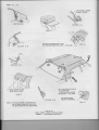
INSTRUMENT
FACIA
S E C T I O NA - A
E
I N S T R U M E N TF A C I A A S S Y .
LIGHT SWITCH
C O N T R O LK N O B
7....-r-.
.-i-KNOB - ENGINE
H O O DC O N T R O L
C A B LE
S P E E DN U T
S C RE W
PANEL - INSTRUMENT
FACIACLOSING
C O V E R- F U S EP A N E L
FrG.3-5
I N S T R U M E NFTA C I A& C L O S I N P
GA N E LI N S T A L L A T I O N
FRONTEND
3-9
3. Disengage end of cable attached to plenum
chamber air duct (see View B, Fig. 3 - 2) and
on LH control cable, ease back clinch over tabs
secuting centre of cable to base of plenum
chamber prior to removing control cable assembly.
lnstollotion
Revetse removal operations.
C L O S I N GP A N E L - I N S T R U M E N TF A C I A
M o d e l s-
All
Removol
1. Remove screws securing closing panel to base
of instrument panel, instrument carrier and
engine hood control cable bracket (see Fig.
3-5).
Instollotion
5. Disconnect heat and demist control cables ftom
top of heat distribution duct assembly (see
Fig. 3 - 7).
6. From inside engine compartment, disconnect
body harness connector from heater impellor
motor.
7. Disconnect inlet and outlet water hoses from
heater assembly (see Fig. 3 - 7).
8. Remove screws and nuts securing blower and
air duct assembly to heat distributlon duct (see
Fig. 3 - 6) then remove blower and air duct
assembly.
9. Remove screw attached retainer securing LH
side of heater core to heat distribution duct.
10. Slacken off screws securing RH heater core
retainer to duct, then withdraw heater core into
engine compartment,LH side first.
Reverse removal operations.
11. From inside vehicle, rem,)ve heat distribution
duct and demist assemblies.
N A M E P L A T E- I N S T R U M E N T
FACIA
I n s t ol l o t i o n
M o d e l s- P r e m i e r ,M o n o r o ,L u x u r y S p o r t s&
Stotesmon
Reverse removal operations, ensuring that the heat
distribution duct cover is effectively sealed (see
sealing note on Fig. 3 - 6).
R e m o v Io
1. Remove instrument facia panel (refer Page 3 -7 ).
2. Renove nuts securing nameplate to instrument
facia then temove nameplate.
NOTE: Run engine at a fast idling speed for five
minutes to ensure full circulation of water
ttuough heater core before topping up radiator.
lnstollotion
Reverse removal operations.
M O T O R& I M P E L L O RA S S E M B L Y- H E A T E R
M o d e l s- A l l
H E A T E R& D I S T R I B U T I O N
DUCT ASSEMBLY
ModelsR e m o v Io
1. Re,nove instrument panel compartment (refer
page 3 -5).
2. Remove LH air outlet from plenum chamber
(refetpageS-4).
3. Remove instrument facia closing panel (see
Fig. 3 - 5).
4. From under instrument panel, remove screws
and butterfly nuts securing demist and heat
distribution duct to instrument panel and heat
distribution duct assembly (see View A, Fig.
3-6).
R e m o v Io
All
1. With engine hood raised, disconnect air induction m')tor to heater resistor lead (see Fig.
3-6).
2. Remove screws securing earth strap and air
induction motor and impellor assembly to air
duct cover and withdraw assemblv.
lnstollotion
Reverse removal operations,
NOTE: For inspection, overhaul and testing of air
induction fan motor, refer VOL. 5, 'HQ'
Electrical Instruments and Gauges.
FRONTEND3-IO
4
DUCT-DEMIST&HEAT
DISTRIBUTION
BUTTERFLY
N U T_ D E M I S T
PTA N E L
D U C TT O I N S T R U M E N
E
t
D U C TA S S Y-. H E A T
DISTRIBUTION
A I R I N D U C T I O NM O T O R& I M P E L L O R A S S Y .
EARTH STRAP
WASHER
H E A T E RC O R E
T I G H T E NM O U N T I N G
AFTER
PLATE SCREWS
ASSY.
HEATER
RESISTORJ
. A P P L Y S E A L E R W I T HA
C O N T I N U O U SR U N
OVER GROOV
FCILLOWING
A P P L Y A C O N T I N U O U SR U N
OF NONHARDENING
SEALER
IN GROOVE
_l
EMALCO
I
B L O W E R& A I R D U C T A S S Y .
s\
& AIRDUCT
S C R E W-S B L O W E R
T O H E A T E RD U C T
T I G H T E NC L A M P S C R E W
A F T E R F I T T I N GR A D I A T O R
Ftc.3-6
M O T O R I S EHDE A T E Ri N S T A L L A T I O N
F R O N T E N D3 - I I
A S S E M B L EC A B L E S W I T H H E A T
A N D D E M I S TC O N T R O LL E V E R S
IN "OFF'' AND"COLD"
POSITIONS
RESPECTIVELY
, . H O T ' 'P O S I T I O N
ON'POSIT
tr
/
'oFF'
I
t-/t
CABLE - HEAT
CONTROL
,/i /
C A B L E - D E M I S TC O N T R O L
\(
\-,
\-V
C O N T R O LA S S Y .HEAT& DEMIST
vtrwB
N O T E : A R R O W SO N I N L E T &
O U T L E T W A T E RN I P P L E S
D E N O T EW A T E RF L O W
D IR E C T IO N .
FtG.3-7
H E A T E R& D E M I S TC O N T R O LI N S T A L L A T I O N
FRONTEND3-12
CONTROLCABLE - HEAT ond/orDEMIST
I n s t oI l o t io n
M o d e l s- A l l
Reverse removal operations.
R e m o v oI
1. Remove instrument facia closing panel (see
Fig. 3 - 5).
WINDSHIELD
G A R N I S HM O U L D I N G
Models -
2. From behind instrument carrier, disconnect
heat and./or demist control cablds) from control
lever(s) (see View B, Fig. 3 - 7).
R e m o v oI
1. Remove screws securing windshield garnish
moulding to insidd of windshield aperture pillar
(seeFig.3-4).
3. Remove instrument panel compartment (refet
page 3 - 5).
4. Disconnect heat and/or demist control cable(s)
ftom control lever(s) on top of heat distribution
duct assembly (see Fig. 3 - 7).
All
lnstollotion
Reverse removal operation.
WINDSHIELD
W I P E RM O T O R ,L I N K A G E o n d W A S H E RA S S E M B L Y
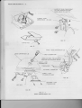
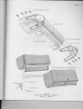
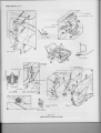
D es c r i p t i o n
The electrically operated windshield wiper assembly illustrated Fig.3 - 8, consists of a two speeil wiper motor attached to links and pivot assemblies that operate wiper blades in a parallel wipe action.
An actuating link attached to the
ddve side wipet tod permits the drive blade to complete its upward travel in a
perpendicular plane, adjacent to the windshield pillar.
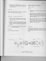
The automatic type waShet pump attached to the windshield wiper motor (see View
B, Fig. 3 - 9) is controlled by a switch mounted button located on the right hand
side of the instrument carrier (see View E, Fig. 3 - 8).
Depressing this button
activates the windshield wiper motor and washer pump simultaneously.
The
knob below this button operates the windshield wiper motor independently.
M O T O R& P U M PA S S E M B L Y- W I N D S H I E L D
WIPER
& WASHER
M o d e l s-
5. Remove screws secuing earth strap to windshield wiper motor and motor to dash panel,
then remove motor.
All
NOTE: Do not remove motor crank attaching nut
as windshield washer operation may be
aftected.
Removol
1. Disconnect
battery gtound cable.
2. Remove shroud ventilator
3 - s).
grille
(refer page
3. Using ignition key, stop motor crank clear of
motor mounting screws to permit removal of
screws.
4. From within plenum chamber, remove clip secudng wiper linkage to windshield wiper motor
crank (see View C, Fig. 3 - 8).
Instollotion
Reverse removal operations, ensuring that motor
crank is in the park position ptiot to installation
of wiper rods and blades (see View C, Fig. 3 - 8).
NOTE: For inspection, overhaul and testing of
windshield wiper motor, refer VOL 5, 'H8'
Electdcal Instrum,-.nts and Gauges.
FRONTEND
3-13
A C T U A TN
I G
LINK
V I E WF
ACTUATING
LINK
WASHER
BUTTON
V I E WE
S H R O U DG R I L L E : 1
Y
I
i\,,
it.
.\-.,' A1 ))
L UCAS
V I E WD
RETAINER
M O T O RC R A N KM U S TB E I N P A R K P O S I T I O N
P R I O RT O I N S T A L L A T I OONF B L A D E S& R O D S
h'Jr^1fiE-
APPLYMOLYBDENUMDI SULPHIDE
C R E A STEO W A S H ED
RU R I N C
A P P L I C A T I OTNOP A R E L L EPLI N
L senrDASHPANEL
v r e wC
A P P L YM O L Y B D E N UDMI S U L P H I DGER E A S E
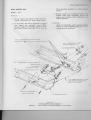
FlG.3-8
WINDSHIELD
W I P E RA S S E M B L Y- I N S T A L L A T I O N
/€€
F R O N T E N D3 - 1 4
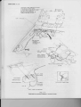
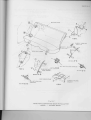
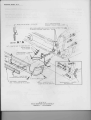
J E T SM U S TS T R I K EW I I D S H I E L D
WITHIN
T H I S4 . O O
D I A , T A R G E TA R E A
I F A D J U S T M E NITS N E C E S S A RBYE N D
O R T W I S TT I P O F N O Z Z L E .
N O Z Z L EM U S TB E C E N T R A LI N
VENTILATOR
G R I L L ES L O T .
t
n
R E T A I NH O S E
IN WIRING
H A R N E SC
S L I P S5 PLACES
t4
I - ' O S -E R E S E R V O I R
TO PUMP
NOTE: ARROWS
D E N O T EW A T E R
F L O WD I R E C T I O N
'- -----=
'-(
NOZZLE
CLIP _ HOOD
LOCK CABLE
FLAT WASHER
WASHER
SPRING
W A T E RR E S E R V I O R
s c R E w- s
L U C A S H O S EC O N N E C T I O N S
R E SE R V O I R
TO FENDER
H O S E- P U M PT O R E S E R V O I R
Ftc.3-9
WINDSHIELD
W A S H E RA S S E M B L YI N S T A L L A T I O N
LH
F R O N T E N D3 - 1 5
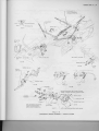
P I V O T& L I N K A S S E M B L I E- S W I N D S H I E LWDI P E R
R O DA S S E M B L-Y W I N D S H I E LWDI P E R
M o d e l s-
M o d e l s-
All
RemovoI
1, Remove rodand blade assembly (refer this page)
2. Remove shroud ventilator gtille.
3. From within plenum chamber, remove screws
secudng LH pivot and link assembly to stuoud
panel (see View B, Fig. 3 - 8).
4. Remove clip securing wiper linkage to windshield wiper motor crank (see View C. Fig.
3 - 8), then disengage inner end of linkage.
5. For removal of RH pivot and link assembly,
remove RH plenum chambet air outlet (see
Fig. 3 - 2).
6. From within RH side of plenum chamber, via
air outlet aperture, remove screws securing
pivot and link assembly to sluoud panel (see
ViewAFig.3-8).
All
Removol
1. Remove blade assembly (refer precefing instructions).
2. On drive side, lift top of clip and slide clip
along actuating link (see View A, Fig. 3 - 8).
3. Position a wide bladed sctewdriver between
shoulder at base of pivot splines and rod, then
prise rod off pivot splines.
I n s t oI l o t i o n
1. Locate wiper rods on pivot splines so that RH
blade is located 1.60" | .16" and LH blade
1.40" I .1.6" above lower section of windshield
reveal moulding.
2. Install actuating link and securing clip to RH
pivot assembly (see View A, Fig. 3 - 8).
lnstollotion
SWITCA
H S S E M B L-Y W I N D S H I E LWDI P E R&
Reverse removal operations.
WASHER
CONTROL
M o d e l s- A l l
WIPER
B L A D E A S S E M B L Y- W I N D S H I E L D
M o d e l s- A l l
I
Removo
1. Insert tip of naftow bladed screwddvet in slot
"A", View F, Fig. 3 - 8 and lever wiper blade
assembly retaining spdng downwards to clear
groove in retaining pin, allowing removal of
blade assembly from rod.
Removol
1. Remove facia panel from instrument carrier
(refer page 3 -7).
2. Remove screws attaching switch assembly to
instrument carrier (see View E, Fig. 3 - 8).
3. From behind instrument catrier, disengage
hamess teuninals from switch, then remove
switch assembly.
l n s t oI l o t i o n
1. Fimly press blade assembly over retaining pin
until blade retaining spring correctly engages
in retaining pin groove.
I n s t oI l o t io n
Revetse removal operations.
NOTES AND BULLETIN REFERENCES
REARQUARTER 1-I
sEcrtoN+
REARQUARTER
I NDEX
Sube
i ct
R e o r Q u o r t e r- D e s c r i p t i o n
R e g u l o t o r- R e o r Q u o r t e rW i n d o w
M o t o r - R e o r Q u o r t e rW i n d o wR e g u l o t o r
W i n d o w- R e o r Q u o r t e r
G u i d e A s s e m b l y- R e o r Q u o r t e rW i n d o w
H o n d l e- R e o r Q u o r t e rW i n d o wR e g u l o t o r - - . - - - - - . T r i m P o n e l - R e o rQ u o r t e rI n n e r- - - - - . - - - - A r m r e s t- R e o rQ u o r l e r
T r i m - R e o r S e o tP o r c e l S h e l f - - - - - - - - - - T r i m - R e o r Q u o r t e rS i d e . . . . - - - - - . . Trim - Wheelhouse
Q u o r t e rT r i m P o n e l F r o n t . . . - - - - - - C o v e r - Q u o r i e rI n n e r P o n e l
W e o t h e r s t r i p- R e o r Q u o r t e rB e l t O u t e r
F i n i s h i n gL o c e - R e o rQ u o r t e rW i n d o w
Poge
4-1
4-3
4-3
4-3
4-5
4-5
4-5
4-6
4-6
4-6
4 -7
4-7
4-8
4-8
4-8
U p p e rW e o t h e r s t r i p
o n d R e t o i n e r - . . - . . . . . . - . . . . . - - - - - - -4- - 9
4-9
S e o l - L o c k P i l l o r U P P e rC o r n e r
4-9
R e l i e fV o l v e - B o d yL o c k P i l l o r - - - - - - - - 4
-9
P r e s s u r eR e l i e f V o l v e - R e o rQ u o r t e rS i d e T r i m
Des c r i P t i o n
The rear quarter innet and outer panels of'HQ' coupes accommodate the vadous
Plastic rollers attached
reEu quarter hardware assemblies illustrated, Fig. 4 - 1.
attached to the
a
guide
assembly
to the sash plate of the quarter window roll in
quarter
window in the
positions
the
A single arm window regulator
inner panel.
desired location.
Forwatd, rearwatd and in and out adjustnent of the qu€utel glass is pnovided by
adjustable studs and slotted holes in the quarter innet panel, and by an adjustable
btacket attached to the lower section of the window guide assembly and quarter
An optional electrically operated teat quarter window tegulator is
inner panel.
available on all coupes excePt 803/437 models.
REARQUARTER 4-2
()
B-B
SECTION
FlG.4-l
R E A R Q U A R T E R H A R D W A R EI N S T A L L A T I O N
M O D E L_ C O U P E
I.
2,
3.
4.
5.
6.
7.
8.
W I N D O WR E G U L A T O R
I N T E R I O RH A N D L E S P R T N G
W I N D O WG U I D E A D J U S T I N GS T U D _ U P P E R
W I N D O WU P T R A V E L S T O P
I N T E R I O RH A N D L E B E A R I N GP L A T E
D O O R A R M R E S T- M O D E L S8 0 8 - 8 I I - 8 I 2 - 8 1 8
WTNDOW
GUTDE
W I N D O WD O W NT R A V E L S T O P
9.
IO.
II.
12.
I3.
14,
15.
16.
D O O R I N T E R I O RH A N D L E
WINDOW
G U I D EA D J U S T I N GB R A C K E T- L O W E R
E L E C T R I C W I N D O WR E G U L A T O RM O T O R- O P T I O N
R E A R Q U A R T E RT R I M P A N E L
- LOWER
WINDOW
G U I D EI N & O U T A D J U S T M E N T
E L E C T R I C W I N D O WR E G U L A T O RS W I T C HS E A L - O P T I O N
E L E C T R T CW I N D O WR E G U L A T O RS W I T C H- O P T I O N
W I N D O WG U I D E F O R W A R D& R E A R W A R DA D J U S T M E N T- L O W E R
R E A R Q U A R T E R4 - 3
R E A R Q U A R T E RW I N D O WR E G U L A T O R
Models -
Coupe
R e m o v oI
1. On GTS and Luxury sports and coqres, remove
reat quarter armrest and on all coupes, rear
quarter window regulator handle (refer page
2. Lock motoi to regulator assembly by using a
l/4" br.ht,3/4" Iong,I.5/8" O.D. flat washer
and an attaching nut attached through hole in
regulator base plate and curved slot in sector
plate.
3. Remove motor to regulator assembly attaching
bolts.
4 -s).
2. Remove rear seat cushion and seat back (refer
page 8 - 1).
3 . Remove rear quarter inner trim panel (refer
page 4 - 5).
lnstollotion
Reverse removal operations, ensuring that fdctional
surfaces of regulatot sector and motor gear are
adequately lubricated with zinc oxide grease or
Iight oil.
4 . Remove screw attached quader inner cover
panel.
5. On models exercising the optional electically
operated window regulator, disconnect electric
harness at motor.
R E A R Q U A R T E RW I N D O W
Models -
Coupe
R e m o v oI
6. With quarter window supported in the raised
position, remove screws securing window regulator to quarter inner panel (see Fig. 4 - 1).
1. On GTS and luxury sports coupes, remove tear
quartet armrest and on all coupes, rear quarter
window regulator handle (refer Page 4 - 5).
7. Disengage window assembly roller from regulator arm cam and remove regulator assembly
out ttuough quarter inner panel aperture.
2. Remove rear seat cushion and seat back (refer
page 8 - 1).
3. Remove rear quarter inner trim panel (refer
page 4 - 5).
l n s t ol l o t i o n
Ensure that frictional surfaces of the quarter window
regulator are adequately lubricated with zinc oxide
grease or light oil prior to reversing removal operations.
4, Remove screw attached quarter inner cover
panel.
5. Remove up-travel stop bracket (see Fig. 4 - 1).
6. Remove quarter belt outer weatherstrip and tear
quarter finishing lace (refer Page 4 - 8).
M O T O R- Q U A R T E RW I N D O WR E G U L A T O R
M o d e f s- O p t i o n o n o l l C o u p e se x c e p t 8 0 3 / 4 3 7
7. Loosen bolt securing adjusting bracket to lower
section of quarter window guide assembly (see
Section A-A, Fig. 4 - 1).
8. Loosen lock nuts locking quarter window guide
assembly upper adjusting studs to quarter inner
panel.
Removo
I
Remove quarter window regulator assembly
( refer preceding instructions).
9. Turn these studs in an anti clockwise direction
to allow window to be positioned for removal
through window aperture.
WARNING: Dc not loosen motor to window regulator attaching bolts prior to performing gperation 2.
10. Raise and remove window assembly out through
window aperture and place on clean protected
surface.
I.
R E A R Q U A R T E R4 - 4
lnsfollotion
Reverse removal operations.
Disossembly
I . With quarter window assembly positioned face
down on a clean protected surface, disengage
tension spring from front roller (see Fig. 4 - 2).
Ad jus tment
Forward, rearward or in and out adjustment of the
rear quarter window is provided by a slotted bracket
attached to the lower section of the guide assembly
and a slotted hole in the quarter inner panel (see
Section A-A, Fig. 4 - 1).
Similar adjustment of the upper section of the guide
assembly is provided by adjusting studs mounted in
the guide assembly and secured through slotted
holes in the quarter inner panel with lock nuts (see
Fig. 4 - 1).
2 . Turn window over and using Tool No. 1A8 (see
Fig. 4 - 3) remove roller tee nuts and plastic
bushings fron- bolts.
3 . Lift glass and weatherstrip assembly off sash
plate and roller assemblies and remove sash
plate filler
A
Slide out weatherstrip ftom retainer on leading
edge of glass
5. Holding glass face down on an insulated surface, tap weathetstrip retainer off glass, sliding
a hammeractoss glass.
WARNING: Ensure that hammer head is smooth
and free from burts, which can damage glass.
-@.
6. Remove and discard old filler strip ftom inside
of weather retainer.
A s s e m bl y
I . Apply a film of liquid soap to rear inner surface
of weatherstrip retainer.
2 . Position glass on its reat edge and place a
new filler strip evenly over leading edge of
quarter window glass.
3 . Locate glass channel of weatherstrip retainer
over filler strip, with end of retainer in line
with top corner of leading edge of glass.
FlG.4-2
R E A R Q U A R T E RW I N D O W
ASSEMBLY
4 . Using a steel strip 6" x 1" x U8" positioned
in weatherstrip channel of retainer, carefully
tap retainer onto glass.
.I.
C H A N N E L- Q U A R T E RW I N D O W
F R O N TS A S H
G L A S S_ Q U A R T E RW I N D O W
W E A T H E R S T R I -P Q U A R T E RW I N D O W
FRONT
F I L L E R - Q U A R T E RW I N D O W
L O W E RS A S HP L A T E
P L A T E - Q U A R T E RW I N D O W
L O W E RS A S H
N U T - Q U A R T E RW I N D O W
G U I D ER O L L E RT E E
B U S H I N G- Q U A R T E RW I N D O W
G U I D ER O L L E R
P I N - Q U A R T E RW I N D O W
G U I D EU P P E RF R T . R O L L E R
S P R I N G- Q U A R T E RW I N D O W
G U I D ER O L L E RT E N S I O N
W A S H E R- Q U A R T E RW I N D O W
GUIDE
L O W E RR O L L E R- R U B B E R
I I . W A S H E R- Q U A R T E RW I N D O W
GUIDE
L O W E RR O L L E R - M E T A L
I 2 . R O L L E R A S S Y .- Q U A R T E RW I N D O W
G U I D EL O W E R
2.
3.
4.
5.
6.
7.
8.
9.
IO.
5 . Apply a film of liquid
soap to weatherstrip
channel of retainer prior to slifing weatherstrip
into channel.
6 . With glass face down, position sash plate
filler, metal washers, sash plate and roller
assemblies over attaching holes in glass.
7
Install plastic bushings and roller tee nuts on
reverse side of glass, torquing tee nuts to 72
in. lbs. (see Fig. 4 - 3).
REARQUARTER 4-5
R O L L E RT E E N U T - 7 2 ' ' L B S .
REGULATOR
HANDLE- REA.RQUARTER
WINDOW
Models-
TOOL NO. IA8
Coupe
R e m o v oI
1. Insert slotted end of door interior handle removal Tool No. 21812X, Fig. 4 - 4, between
base of handle and bearing plate and in line
with arm of handle, disengaging horse-shoe
shaped retaining spring and releasing handle.
T O R Q U EW R E N C H
FlG.4-3
R O L L E RT E E N U T I N S T A L L A T I O N
- REARQUARTERWINDOW
GUIDEASSEMBLY
Models- Coupe
Removol
1. On GTS and Premier coupes, remove teat quarter
armrest and on all coupes, rear guarter window
regulator handle (refer this Page).
2. Remove tear seat cushion and seat back (refer
Page I - 1).
lnstollotion
1. Locate horse-shoe shaped retaining spdng in
handle with open ends of spring towards ann of
handle and press spring into the engaged
position.
2. Install handle beadng plate into regulator
splines with raised face towards door.
3. Press handle onto regulator until retaining
spdng engaSes behind splines, ensuring that
the handle is positioned as illustrated (see
Fig. 4 - 4).
3. Remove rear quarter inner tdm panel (refer
this Page).
4. Remove screw attached quarter inner cover
panel.
5. Remove bolt securing lower section of guide
assembly adjusting bracket to quarter inner
- f)'
panel (see Section A-A, Fig. 4
6. Remove lock nuts locking quarter window guide
assembly upper adjusting studs to inner panel'
7. Tum adjusting studs anti-clockwise until they
become disengaged from guide assembly'
8. Loosen window regulator attaching sctews and
slide regulatot arm cam off quarter window
roller.
T R I M P A N E L - R E A R Q U A R T E RI N N E R
M o d e l s- C o u p e
Removol
1. On GTS and luxury sports coupes, remove rear
quarter armtest and on all coupes, reat quarter
window regulator handle (refer pteceding instructions).
2. Remove rear seat cushion and seat back (refer
Page 8 - 1).
T O O LN o . 2 1 9 1 2 X
R E T A I N I NS
GP R I N G
DISENGAGED
9. Disengage guide assembly from quarter window
tollers and remove assembly out ttrough quartet
inner Panel aPefiure.
Instollotion
P U S HT O O L I N
D I R E C T I O NO F A R R O W
I N S I D EH A N D L E
Reverse removal opetations.
NOTE: Refer to quarter window adjustment, page
4 - 4, for adjustment of guide assembly.
FtG.4-4
WINDOW
R E G U L A T O RH A N D L E R E M O V A L
R E A R Q U A R T E R4 _ 6
A R M R E S T- R E A R Q U A R T E R
Models - All Coupes excePt 803/437
INNER
QUARTER
T R I MP A N E L
R E T AN
I IN C
BRACKET
SECTIONA-A
Removol
1. Remove sctews installed through lowet section
of aunrest, which secure atmtest to rear quartet
inner panel, removing armresL
I n s t oI l o t io n
REAR
QUARTER
Apply caulking compound around aunrest to rear
quarter inner panel attaching screw holes prior to
reversing temoval operations.
I N N E RP A N E L
SECTIONB-B
TRIM- REARSEATPARCELSHELF
F I N I S H I NLGA C E
Models FtG.4-5
R E A RQ U A R T E RT R I MP A N E LR E M O V A L
M O D E L- C O U P E
3. Loosen screw securing tear end of sill plate
to rocker panel, then remove finishing lace ftom
leading edge of rear quader panel (see Fig.
4-5).
S e d o no n d C o u p e
RemovaI
1. Remove rear seat cushibn and seat back (refet
Page 8 - 1).
2. With rear compartment lid open, tap out parcel
shelf plastic fastenets which prottude through
rear parcel shelf into tear comparknent.
3. Lift out reat parcel shelf.
4. Remove plastic sleeve covering seat belt attaching bolt, then remove bolt and associated
parts.
5. Carefully ease off leading edge of trim panel,
whichis attached tpleading edge of rear quarter
panel with adhesive cement.
6. Remove screws secuing rear lowet and upper
end of tdm panel to reat quader inner panel.
7. Using a wide bladed sctewdriver positioned
between leading edge of trim and rear quarter
inner panels, carefully prise trim panel clips
from inner panel (see Fig. 4 - 5).
N o T E: On models fitted with the electric window
regulator, disconnect switch from back of
rear quarter tdm panel.
8. Partly raising lower end of him panel inboaril,
push ttim panel up, off quater inner panel
tetaining brackets, removing trim panel.
lnstollotion
Revetse removal opetations, using new plastic
fasteners to secure tdm panetr to rear parcel shelf.
T R I M - R E A R Q U A R T E RS I D E
Models - Stotion Sedon
Removol
1. Remove rear seat cushion and lower tear seat
back (refer Page 8 - 1).
2. Loosen sctews secudngrear sill plate to rocker
panel.
3. Ease finishing lace covering leading edge of
trim panel off rear body lock piIlar.
Instollotion
Reverse removal operations.
4. Remove screw securing rearlower comer of trim
panel to rear lamp access aperfure.
R E A R Q U A R T E R4 - 7
5. Ease off leading edge of rear quarter side trim,
which is attached to flange of rear body lock
pillar with trim adhesive.
6. Using a 3/8" sharp wood chisel positioned
between tdm panel and head of fastener, tap
end of chisel shalply to pare off head of
fastener.
Altematively, a special tool fabricated to dimensions illustrated in Fig. 4 - 5
can be used to punch centre of fastener through
trim panel, taking care to centralize punch with
centre of fastener.
7. On Kingswood and Belmont models, ease base
of trim panel inboard, fisengaging top edge of
panel ftom trim retainer.
On Premier models,
position a wide bladed screwdriver between
tdm and quarter panels, ptising under each
fastener until trim panel is disengaged.
8. Remove or smooth out any hardened adhesive
cement ftom flange of rear body lock pillar.
3. Remove lear seat back stop.
4. Remove outer seat belt lower attaching bolt.
5. Remove rear quarter tdm panel and quarter triur
panel front. (refer Page 4 - 5 and following
instructions).
6. Remove screw securing ftont end tonneau floor
sill panel covering to sill panel, easing back
covering sufficient to remove wheelhouse cover.
7. Ease off edges of wheelhouse cover,whichare
attached to rear quarter and floor panels with
trim adhesive.
8. Clean or smooth off any hardened adhesive
from rear quarter and floor panels.
Instollotion
I n s t ol l o t i o n
Reverse removal operations, ensuring that during
installation of the rear seat back stop and outer seat
belt lower attaching bolt, caulking compound is used
to seal around attaching holes.
Reverse removal operations, attaching leading edge
of rear quarter side tdm to flange of rear body lock
pillu with PVC adhesive cement and using new trim
fasteners, install lower section of trim panel to rear
quarter inner panel.
Q U A R T E RT R I M P A N E L F R O N T
Models -
MATERIAL.
Bright round
mild steel
L16 DrA
S t o t i o nS e d o n
Removo
I
I
1. Lift out rear seat cushion.
2. Remove rear sill
plate (refer Page 2 -
1).
k""oo.
FtG.4_6
T R I M F A S T E N E RR E M O V A LT O O L
3. Remove finishing lace covering leading edge
of quarter trim panel ftont.
4. Ease leading edge of tdm panel, which is
attached to the rear door aperture flange with
trim adhesive.
T R I M- W H E E L H O U S E
Models- StotionSedonexceptBelmonr
R e m o v Io
1. Remove rear seat cushion and back (tefer page
8-t).
2.
Remove spare wheel cover and ftont tonneau
floor (refer Page I - 1).
5. Using a wide bladed screwdriver positioned
between trim panel and tear quarter panel, pdse
plastic fasteners ftom rear quarter panel.
6. Clean or smooth off any hardened adhesive ftom
rear door aperture flange.
Instollotion
Reverse removal operations.
REARQUARTER 4-8
I N N E RP A N E L
C O V E R- Q U A R T E R
W E A T H E R S T R I -P R E A R Q U A R T E RB E L T O U T E R
Models- Coupe
M o d e l s- C o u p e
Removol
R e m o v oI
1. On GTS and luxury sports coupes, remove rear
quarter armtest and on all coupes, rear quarter
window regulator handle (refer Page 4 - 5).
1. Remove quatter belt moulding and attaching
clips (refet Page 12 - 1).
2. Remove rear seat cushion and seat back (refer
Page 8 - 1).
2. With rear quattet window fully lowered, remove
screws secudng weatherstrip assembly to reat
quarter outer panel (see Fig. 4 - 7).
3. Remove rear quarter inner tdm panel (refer
Page 4 - 5).
4. Remove sctews securing quartet inner covet
panel to rear quartet inner panel and remove
cover panel.
I n s t ol l o t i o n
Reverse removal opetations.
I n s t o ll o t io n
1. Appty a continuous bead of caulking compound
around eerture in rear quarter innet panel prior
to reversing removal operations.
F I N I S H I N GL A C E - R E A R Q U A R T E R W I N D O W
M o d e l s- C o u p e
R e m o v oI
BELT - WEATHERSTRIP
1. On GTS and luxury spotts coupes' remove teat
quarter armrest and on all cotpes, tear quatter
window regulator handle (see Fig. 4 - 4).
2. Remove tear seat cushion and seat back (refer
Fig. 8 - 1).
R EA R Q U A R T E R
BE L T MOULDING
3. Remove tear quattet innet trim panel (refer
Page 4 - 5).
4. Ease rear finishing lace off quarter inner panel
(see Fig. 4 -5 ).
Instollotion
Reverse removal opetations.
FlG.4 -7
O U T ER B E L T W E A T H ER S T R I PI N S T A L L A T I O N
,l
REARQUARTER 4-9
AND RETAINER
U P P E RW E A T H E R S T R I P
Models -
B O D YL O C KP I L L A R
Coupe
S E A L - R E L I E FV A L V E
R e m o v oI
R E L I E FV A L V E
1. With doot open, lower rear quader window on
side from which weatherstdp and/or tetainer is
to be removed.
2. Ease weatherstriP, the front end of which is
attached to tetainer with neoprene cement, out
of retainer.
3. Remove screws secudng weathersttip tetainer
to roof side rail, then remove tetainer.
4. Remove or smooth off any hardened sealet from
weatherstrip retainer and/ot roof side rail.
I n s t oI l q t io n
Apply a continuous bead of plastic sealer between
retainer and roof side tail pdorto reversing temoval
operations.
S E A L . L O C KP I L L A RU P P E RC O R N E R
FlG.4-8
L O C K P I L L A R R E L I E FV A L V E I N S T A L L A T I O N
Models- Coupe
R e m o v oI
1. Remove screw securing leading end of quarter
belt moulding to rear quarter outer panel.
2. Ease off seal, which is attached to lock pillar
uppet cotner with Neoprene cement.
2. Ease out bottom of valve, then disengage
mainder of valve ftom lock pillat.
lnstollotion
Reverse temoval operations.
3. Remove or smooth out any hardened cement
remaining on lock pillar.
I n s t oI l o t io n
Revetse removal opetations.
P R E S S U RREE L I E FV A L V E- R E A RQ U A R T E R
S I D ET R I M
Models- StctionSedon
R E L I E FV A L V E- B O D YL O C KP I L L A R
Models -
All
R e m o v oI
Remove sctews secudng pressute relief valve
rear quartet side trim, then ease out valve.
R e m o v Io
lnstollotion
1. Remove screw securing lower end of relief
valve to body lock pillar (see Fig. 4 - 8).
Reverse temoval operations.
NOTES AND BUTLETIN REFERENCES
REARCOMPARTMENT5-I
sEcTroN5
INDEX
S u bj e c t
Poge
R e o rC o m p o r i m e nLti d A s s e m b l y- D e s c r i p t i o n
5-l
5-3
5-3
5-3
5-4
5-4
5-4
5-5
5-5
R e o r C o m p o r t m e nLt i d . . . . - . . . . . - . .
T o r q u e R o d s - R e o r C o m p o r t m e nLti d
C y l i n d e r- R e o rC o m p o r i m e nLti d L o c k
L o c k - R e o rC o m o o r t m e nLti d
S t r i k e r- R e o r C o m p o r t m e nLt i d L o c k
R e o r C o m p o r t m e nLt o m p & S w i t c h
P e t r o lF i l l e r D o o r
W e o f h e r s t r i p- R e o r C o m p o r t m e nLt i d
L I D A S S E M B L Y- R E A R C O M P A R T M E N T
Description
The reat compattment lid assembly (see Fig. 5-I) is operated by torsion tods attached to
each hinge.
These assist as a counter balance when raising the lid and hold lid in the
raised position when lid is open.
Retaining notches are provided at each hinge for
torsion rod adjustment (see View D, Fig. 5-1).
The lid lock,which is operated by the
lock cylinder and key, releases when the key is tumed.
When the lid is closed, the
spdng loaded lock bolt engages with and locks behind the striker.
Lid adjustnents
are provided for at hinge attachments and lock striker.
REARCOMPARTMENT5-2
L U B R I C A TE R E A R C O M P A R T M E N T
L I D L O C K S T R I K E RW I T H Z I N C
O X I D E G R E A S EO R L I G H T O I L
S T R I KE R - R E A R
C O . M P A R T M E N TL I D L O C K
VIEW C
VIEWA
H I N G E- R E A R C O M P A R T M E N LT I D
/
R E A R C O M P A R T M E N LTI D
L O C K C Y L I N D E RA S S Y .
L U B R I C A T EH I N G E P I N S& B E A R I N G
S U R F A C E SW I T HG R A P H I T EG R E A S E
G A S K E T- L O C K
ASSY.
\YLTNDER
roRSroN
RoDS
\
)
R E T A I N E R- T O R Q U ER O D
G A S K E T- L O C K
C Y L I N D E RR E T A I N E R
VtEW D
R E T A I N E R- L O C K
C Y L I N D E RA S S Y .
LOCK ASSY.
VIEW B
FlG.5-l
R E A R C O M P A R T M E N TL I D
R EA R COMPA RTME,NT,5,r"*
R E A R C O M P A R T M E N TL I D
TORQUE RODS- REAR COMPARTMENTLID
Models-Sedqn&Coupe
Models- Sedon&Coupe
Removol
Removol
l.
Raise rear compartment lid and place a protective cover over adjacent paint finish sutface.
2. Pencil scdbe location of hinge shap on lid
inner panel to facilitate installation.
3. With the aid of an assistant to support lid,
remove hinge to lid attaching bolts (see View
D, Fig. 5-1) then remove lid assembly.
I n s t oI l o t i o n
Reverse removal operations.
'T
1. Raise and support compartment lid.
2. Pencil scribe location of torque rod on retainer
to facilitate installation.
3. Using a length of steel tubing approximately
12" long, with an inside diameter of. L/2" ,pIace
one end of tube over end of torque rod, then
lever torque rod ftom retainer.
4. Disengage opposite end of totque rod from
hinge assembly (see View D, Fig. 5-l) then
remove rod.
Instollotion
Reverse removal operations.
A di u s t m e n t
/
D
Elongated holes in the hinge straps pnrvide
forward, rearward and side adjustnent of the lid.
Hodzontal adjustment of the hinge area of the lid
can be achieved as follows:(a) To raise lid at hinge area, place a shim between lid inner panel and one or both hinge
straps at forward attaching bolt locations.
(b) To lower lid at hinge area, place a shim be
tween lid inner panel and one or both hinge
straps at rearward attaching bolt locations.
Adjust lock striker to allow rear compartment
lid to seat firmly on rubber bumpers located
on each side of compartment lid (see View A,
Fig. 5-l).
A dj u s t m e n t
The position of the torque rods in notches of the
retainer determine the amount of effort required to
open and close the rear compartment lid.
If the
torque rod is located in the lowest notch of the
retainer, a greater amount of effort is required to
open the lid and less effort required to close it.
If the torque rod is located in the top notch of the
retainer, the effect is opposite.
To adjust the
totque rods, position a length of tubing apprcximately 12" long, with an inside diameter of !/2"
over end of torgue tod, then lever torque. rod ftom
retainer.
C Y L I N D E R - R E A R C O M P A R T M E N TL I D L O C K
IMPORTANT: Following any adjustmentof the rear
compartonent lid, it is important that the lid lock
stdker engages correctly with the lid lock.
To
check correct engagement, place a small piece of
plasticine or similar matedal at each side of the
lock bolt cover and close lid.
Open lid and check
engagement of lock cover with striker.
Where
required, adjust striker so that lock engages centrally with stdket
Models-Sedon&Coupe
D e s c r ip t io n
The lid cylinder is attached to the rear compartment
lid with a screw attached retainer (see View B, Fig.
5-l).
A rubber gasket between the retainer and
rear comparknent lid seals against dust and waten
entry into the body.
R E A R C O M P A R T M E N5T- 4
LID LOCK
STRIKER- REARCOMPARTMENT
Removol
1. Remove lock cylindet retainer attaching sctews.
Models-Sedon&Coupe
2. Apply masking tape adjacent to tetainer to protect paint finish.
Removol
3. With a wide bladed screwdriver inserted between
flange of retainer and lid inner panel, partly
prise retainer out (apptoximately 1/2") then
withdraw 1ock cylinder.
1. Pencil scribe location of lock striker on tear
end inner panel to facilitate installation.
2. Remove bolts secudng lock striker to rear end
inner panel (see View C, Fig. 5-1) then remove
striker.
I n s t ol l o t i o n
I ns t ol l o t i o n
Reverse temoval operations.
NOTE: Due to the adverse effect of dust on lock
cylindet operation, it is advisable whenever
the lock cylinder is temoved, to wash it with
petrol, dry it with an air hose and lubricate it
with powdered graphite.
DO NOT USEOIL.
Position lock striker within
install attaching bolts.
scribe
marks and
Adiustment
Slots inrear face of lock striker provide adjustment
for stdker.
L A M P S W I T C H- R E A R C O M P A R T M E N T
M o d e l s- S e d o n& C o u p ee x c . B e l m o n t& K i n g s w o o d
L O C K - R E A R C O M P A R T M E N TL I D
Models-Sedon&Coupe
R e m o v oI
1. Disconnect battery ground cable.
Removol
1. Remove rear compattnent lid lock cylinder (refer
preceding instructions).
2. Remove bolts secudng lock to tear compartment
lid inner panel (see View B, Fig. 5-1) then
remove lock.
Instollotion
Reverse removal operations and dheck operation of
lock.
2. Withrear compartmentlid raised, depress switch
plunger from bracket attached to RH front of
rear comPartment gutter, then remove harness
terminal from base of plunger, disassembling
switch (see Fig. 5-2).
3. Using a thin bladed screwdriver,
prise switch body from bracket.
carefully
I n s t ol l o t i o n .
Reverse removal operations.
L I G H T M U S TB E O F F J U S T B E F O R E
L I D I S C L O S E D . B E N D B R A C K E TI F
NECESSARY
T O A C H I E V ET H I S C O N D I T I O N .
FlG.5-2
REARCOMPARTMENL
T A M P & S W I T C HI N S T A L L A T I O N
M O D E L S- S E D A N& C O U P EE X C . B E L M O N T& K I N G S W O O D
5 T* 5
REAR COMPARTMEN
PETROLFILLER DOOR
N U M B E RP L A T E
fi
SECTION
FRI:;J;I
w E A T H E R s T R IcPL I P
* ,*,,olr-ING TooL
A-A
Removol
F l G .s - 3
P E T R O LF I L L E RD O O RI N S T A L L A T I O N
P E T R O T F I L L E R D O O RA S S E M B L Y
Models-Sedon&Coupe
Removol
1. Using weatherstrip clip inserting tool No. 1A4,
(Fig. 5-4), or a similar suitable tool at clip
locations, carefully pdse clips ftom retaining
holes.
2. Check weatherstrip clips for conect shape and
reform if necessaty, using clip refotming tool
No. 1.{3, (Fig. 5-5).
l ns f o l l o t i o n
Revetse removal opetations.
1. Remove screws secudng reat license number.
plate to petrol filler doot (see Fig. 5-3) and
remove plate.
2. Remove nuts and bolts securing petrol filler
door assembly to back Panel lower.
I n s t oI l o t i o n
Reverse temoval operations.
W E A T H E R S T R I P- R E A R C O M P A R T M E N TL I D
Models-Sedon&Coupe
The rear compEutment weathetstrip is a constant
rubber section, secuted in position with wite clips
inserted into holes at tegulat intervals around the
reat computment lid. .
FlG.5-5
TOOL
WEATHERSTRIC
PLIP REFORMING
NOTES AND BULLETIN REFERDNCES
END GATE'6 - I
sEciloN 6
END GATE
INDEX
S ub i e c t
Po g e
E n d G o t e - D e s c r i p t i o n- - . - . - - - - - . - . - - - - - - -6- ---l.
R e g u l o t o r- E n d G o t e W i n d o w
6-4
M o t o r E l e c t r i c o l l y O p e r o t e dW i n d o w
R e g ul o t o r
6-4
Lock Assembly .-.---.------
6-5
6-5
Lock Striker
LimitArm
S u be
i ct
Poge
W e o rS t r i p s & T r i m P o n e l I n n e r
H q n d l e- W i n d o wR e g u l o f o r
6 -7
6-8
L o c k C y l i n d e r& C o p A s s e m b l y
E l e c t r i cS w i t c h& E s c u t c h e o n
Assembly
6-8
6-9
S o f e t yS w i t c h- E l e c r r i c o l l y O p e r o r e dE n d G o t e
W i n d o wR e g u l o t o r
I n t e r i o r H o n d l eo n d R e m o t eC o n t r o l
6-9
T o r q u eR o d - - - - . - . - . - - -
6-6
6-6
E n d G o t eA s s e m b l y
6-6
- Lower End Gote Aperture
Weotherstrip
6-10
Weothersfrip
O u t e r- E n d G o t e B e l t . _ - _ . _ _ _ _ _ - - _ _ _ - . -
H i n g eA s s e m b l y
6-7
6-7
GlossRunChonneL
l o w e r& R e t o i n e r
G I o s s R u n C h o n n e lU p p e r & R e t o i n e r
W i n d o wA s s e m b l y
E N DG A T E
Descripiion
The, manually conttolled end gate window regulator is operated
by a folding handle located centrally in the end gate outer panel {"eu nig. O_f).
The optional electrically
two switches:
operated end gate window regulator can be operated by one
of
1. A switch located to right of steering corumn, at base of
instrument paner,
operable only with ignition switch',ON..
2. A key-operated lao5k gfli^ndet switch, located cenhally in end gate outer
panel
escutcheon (see Fig. 6-2).
A safety switch located above the LH end.gate lock prevents operation of electdcally
controlled end gate window tegulator when thl end gate is not completely closed.
Aftu.
lo-wedng window, the end gate can be opened by a=remote control handie situated
centrally above the end gate inner trim panel.
The end gate is counter balanced with a single torque rod secured to the RH side
of the
reat end panel and to the end gate inner panel with retainer plates.
When the end
gate is opened, the end_of the torque rod secured to the body remains stationary whilst
the temainder of the rod moves with the end gate, thereby creating an assistini torque
for lowering and raising the end gate.
6-10
6-r0
6 - ll
6 - ll
ENDGATE6-2
:q0
-re
10
LEGEND
1. Handle - Window Regulator
2. Gasket - Window Regulator
3 . Handle - Remote Control
+
5.
6.
7
R
9.
10.
11.
72.
13.
14.
@*a
Remote Control - End Gate
Insulator - End Gate Remote Control Rod
Lifter Channel - End Gate Window
Cam - End Gate Window Lifter Channel
Rod - End Gate Remote Control
Lock - End Gate
Limit Atm - End Gate
Hinge Assembly RH - End Gate
Retainet RH - End Gate Toque Rod'
Burnper - End Gate Glass StoP
Bumpet - End Gate Limit Arm StoP
15.
16.
17.
18.
19.
Totque Rod - End Gate
Retainer - End Gate Glass Rur Charurel
Regulator - End Gate Window
Hinge Assembly LH - End Gate
Retainer LH - End Gate Torque Rod
FIG.6-I
E N D G A T E H A R D W A R EI N S T A L L A T I O N
ENDGATE6-3
/
/
\
---q@
-a@
16
\\'\
LEGEND
1.
2.
34.
5.
6.
7
8.
9.
10.
11.
t2.
13.
14.
15.
Escutcheon - End Gate Switch
Lock Cylinder Case & Switch Assemblv
Gasket - End Gate Switch Escutcheon
Cover Plate - Window Regulator Motor
Cam - End Gate Window Lifter Channel
Handle - R.emoteControl
Connector - Window Regulator Control Switch
Lifter Channel - End Gate Window
Remote Control - End Gate
Harness - Window Regulator Safety Switch
Safety Switch - End Gate
Retainer - End Gate Glass Run Channel
Rod - End Gate Remote Control
lnsulator - End Gate Remote Control Rod
Lock - End Gate
16.
17.
18.
19.
20.
21.
'))
Y*^
Limit Arm
Seal - Window Regulator Hamess to Bodv
Hamess - Electric Window Regulator
Seal - Window Regulator Fiamesb to End Gate
Bumper - End Gate Limit Aun Stop
Motor - Electric Window Regulatoi
Torque Rod - End Gate
23. Regulator - End Gate Window
)A
Bumper - End Gate Glass Stop
25. Hinge Assembly - End Gate
2 6 . Retainer - End Gate Torque Rod
FtG.6_2
E N D G A T E H A R D W A R EI N S T A L L A T I O N
M O D E L S- O P T I C N A L O N K I N G S W O O&D P R E M I E RS T A T I O N
SEDAN
ENDGATE 6-4
- ENDGATEWINDOW
ASSEMBLY
REGULATOR
M A N U A LO R E L E C T R I C
M O T O R- E L E C T R I C A L L Y O P E R A T E D
W I N D O WR E G U L A T O R
Models - Stoiion Sedon
M o d e l s- O p t i o n o lo n K i n g s w o o d& P r e m i e r
S t o t i o nS e d o n s
R e m o v oI
Removol
1. Open end gate and remove wear stdps and inner
trim panel (refer page 6 - 7).
1. Open end gate and temove wear strips and innet
trim panel (refer page 6 - 7').
2. Raise and support end gate window.
2. Raise and suppott end gate window.
operated window regulators,
3. On electrically
disconnect regulator motor hamess.
4. Remove bolts securing window regulator to end
gate (see Fig. 6 - I or 6 - 2).
5. Disengage regulator arm rollers ftom liftei cams
and remove regulator assembly through aPerfute
in end gate inner panel.
CAUTION: Do not oPerate regulator motor after
Operation
regulatot is removed ftom end gate.
of the motor with load r6moved may damageunit.
l n s t o ll o t i o n
Clean and lubricate regulator sector teeth with zinc
oxide grease or light oil pdot to revetsing removal
opetations.
3. Disconnect regulator motot hamess.
4. Remove screws secudng motor to window reg.
ulator and remove motor (see Fig. 6 - 2).
Instollotion
Clean and lubricate tegulator motot geat teeth sparingly with zinc oxide grease or light oil priot to
reversing removal oPetations.
CAUTION: The following opetation MUST be pea
formed if the motor is disengaged from the
regulator in any but the fully taised position.
The regulatot lifter arms, which are under
tension ftom the counter-balance spring, can
cause serious injury if the motor is temoved
without locking the sector gears in position.
G A R N I S HM O U L D I N G
WEATHERSTRIP
LOCK STRIKER
L IMIT ARM
REMOTECONTROL HANDLE
L ENDGATE ASSEMBLY
BUMPER
FrG.6-3
SEDAN
R E A RE N D- S T A T I O N
ENDGATE 6-5
Drill a I/8 in. dia. hole through regulator sector and
back-plate - DO NOT drill th; hol-e closer than I/2
in. to edge of sector back-plate.
Install a pan
head self
(10-12 x 5/8,,) in
screw
_tap_ping.
ireviou'sly drilled 1,28 in. dia. hole to lock regulator
sector gear to retain counter-balance spring tlnsion.
NOTE: For servicing end gate electrically
operated
rllndow regulator motor, tefer Volume-s, .He'
Electrical Service Manua1.
LOCK ASSEMBLY
S PA C E R
AS REQUIRED
M o d e l s- S t o r i o nS e d o n
Removol
1 . Open end gate and remove weat strips and inner
trim panel (refer page 6 - 7\.
2 . Raise and support end gate window.
3 . Remove lower glass run channel on side ftom
which lock is to be removed.
4. Remove screws securing lock to side of end
gate (see Fig. 6 - 1 or 6 - Z).
STRIKER
5. Disengage lock ftom remote control rod and
remove lock.
Instollotion
1. Ensure ftictional surfaces of lock are adeggqtely lubticated with zinc oxide grease or
light oil.
2. Apply caulking compound around face of
lock
ftame.and rotary bolt prior to reversing removal
operations.
LOCK STRIKER
M o d e l s - S t o t i o nS e d o n
Removol
1. Pencil scribe around striker assembly on
lock
pillar to facilitate installation.
2. Remove screws se,curing striker assembly
to
rear end aperture pillar (see Fig. 6 _ 4).
Instollofion
|pply " ribbon of caulking compound around inner
face of sttiker assembly
attaching holes
"id operations.
".."*
pdor to reversing removal
Ftc.6_4
L O C KS T R I K E R
ASSEMBLY
Adiustment
l. To adjust striker lrorizontally
or vertically,
loosen screws secudng sttkei'assemiiy
to ,.".
pillar, move striker to the desired
.aperture
,bod1
locatlon, then tighten attaching screws.
2. To.adjust-striker away from rear
body aperture
pillar and to ensure correct engagement
of
striket and end qate, lock, .rnu.g"i.-y
=p...."
should be install"eo between striker
and lock
pillar.
The end gate
shodJ-1. .orr..Uy
-apertur.
aligned with tear body
bufo_. .fr..f*rrg
gate lock spacer requirements.
To
:n9
qerermrne rt end gatelock striker emergency
al, apply plasticine o.
behind the tooth plate
; housing engages, then
rm an impression in the
compound as shown in
ftominside
faceof
f,.r':,i':;.t;J;
of lock housing is ".til.".T3ln
less th"" ItJt;r,],
in"ol
emergency spacers in accoldance
with the
following table:-
ENDGATE
6-6
TORQUE ROD
Models - Stotion Sedon
Removol
1. 'Remove tear tonneau floot.
2. Remove reat bumper assembly (tefer pages
l4-2, I4-3 otl4-4\.
T I C I N EO R
KING
OUND
3. Position end gate vertically to telieve tension
ftom torque rod, then remove retainet securing
torque rod to body back panel lower. (see Fig.
6-1or6-2\.
4 . Remove wear strips and inner trim panel (refer
page 6 - 7).
5 . Raise and support end gate window.
6 . Remove screws securing torque rod retainer
to end gate, then remove torque rod.
Flc.6-5
L O C KS T R I K E R
ADJUSTMEN
CTH E C K
D imension
"/rr"
1o
"/rr"
5
7t ll
/sZ
ro
'A'
n
/rr"
'/rr"
No. & Size of
Spocers Required
t
/rr"
6
t/rztt
Apply caulking compound atound screw and bolt
attaching holes in body back panel lower and in end
gate pdor to reversing removal opetations.
| - tA""
| _yr"
t
5r rr
/SZ
lnstollotion
l/
tl
,t - / 1 6 !, ,,-lotol31ro'
2 - ' A ' T o r ol "
'B'
ftom centte of lock housing to inside
Dimension
face of striker should not be less than L/8 in.
LIMIT ARM
Models - Stoiion Sedon
Removol
1. With end gate open, provide support for side
from which [mit arm is to be temoved.
2. Remove screws securing limit arm to end gate
and bolts securing limit arm to rear end aperture pillar (see Fig. 6 - 1 or 6 - 2).
l n s t ol l o t i o n
Apply caulking compound around screw and bolt
attaching holes in end gate side and rear body
aperture pillar, priot to reversing removal operations.
END GATE ASSEMBLY
Models - Stotion Sedon
Removol
1. Remove rear tonneau floor.
2. Remove rear bumber assembly (refer pages
I4-2, l4-3 or 14-4).
3. Position end gate vertically to relieve tension
ftom torque rod, then remove retainer secudng
torque rod to body back panel lower. (see Figs.
6-1or6-Z).
4. Fully open and support end gate.
5. Remove screws and bolts securing hinges and
limit amrs to end gate, then remove end gate.
NOTE: On end gate exercising the optional electric
window regulator, disconnect wiring harness
inside spare wheel compartment, temove
wiring sleeve ftom body back panel lower
and remove hamess.
END GATE
Instollotion
WINDOWASSEMBLY
Apply plastic sealer between hinge and limit am to
end gate moturting surfaces prior to reversing removal
operations.
M o d e l s - S t o t i o nS e d o n
N OT E: O,n end gates exercising the optional
electric window regulatot, ensure thit end
gate- wiring hamess sleeve is effectively
bonded to body back panel lower with
neoprene cement.
R e m o v oI
1. Open end gate and remove wear strips, inner
trim panel and inner belt lacing (refer page
6-1).
2. Partly raise and support end gate window to
gain access to glass lifter channel cam attaching bolts (see Fig. 6 - I or 6 - 2\.
A di u s t m e n t
Horizontal and/or vertical
gate can be achieved by:
l.
adjustment of the end
Loosen end gate hinge to body attaching bolts.
2. Position
3. Remove glass lifter channel cam attaching
bolts and cams from lifter channel.
4. Remove window through top of end gate and
place on a clean protected surface.
end gate in the desired location.
- 3. Tighten end gate hinge to body attaching bolts.
CAUTION: Any end gate adjustments necessitate
CAUTtoN: On models fitted with electrically
operated window regulator, do not operate
regulatot motor after regulator is removed from
end gate.
Operation of the motor with load
removed may damage the unit.
Instollotion
Lubricate regulator sector teeth with zinc oxide
grease or light oil prior to reversing removal operations.
H I N G EA S S E M B L Y
Models- Stotion Sedon
Removo
I
1. Open and srryport end gate on side from which
'
hinge is to be removed.
W E A RS T R I P S
A N DT R I MP A N E LI N N E R
Models - Sioiion Sedon
Removol
2. Pencil scdbe around hinge assembly to facilitate installation.
3. Remo-ve hinge to body and hinge to end gate
attaching screws and bolts (s.. nig. 6 _ i o,
6 - 2\ then remove hinge
Instollotion
Apply plastic sealer between mating surfaces
of
hinge to body and hinge to end gate pto'r to reversing
removal operations.
1. Open end gate and remove screws securing
wear strips and trim panel to end gate inner
panel.
I n s t ol l o t i o n
ENDGATE
6-8
HANDLE- WINDOW
REGULATOR
Assembly
Models- StotionSedon
Clean and lubdcate frictional surfaces of handle
assembly with zinc oxide grease or light oil priot
to revetsing removal opetations.
Removol
1. Open gate and remr)ve wear. strips and inner
trim panel (refet preceeding instructions).
LOCK CYLINDERAND CAP ASSEMBLY
2. Raise and suppott end gate window.
M o d e l s- S t q t i o nS e d o n
3. From inside end gate, remove nuts securing
outside handle assemblv to outet panel, then
remove assembly (see Fig. 6 - 1 ot 6 - 2).
Removol
1. Remove window regulator handle (refer preceeding instructions).
l ns t ol l o t i o n
1. Ensute that handle assembly gasket effectively
seals handle aperture in outer panel.
2. Check operation of regulator handle pdor to
replacing innet tdm panel.
D i s o ss e m b l y
1. Remove clutch retaining spdng and slide clutch
off shaft of handle drivet (see Fig. 6 - 6).
2. Using a snap ring removal tool, temove handle
retaining spring and spdng washer from shaft
of handle ddver and temove handle assembly
from escutcheon.
3. Remove screws securing handle driver hinge
pin to handle arrd knob assembly.
2. Remove clutch retaining spdng and slide clutch
off shaft of handle ddver (see Fig. 6 - 5).
3. Insert key in lock cylinder and turn key to lock
position.
4. Depress locking pawl, turn key (lock cylinder)
approximately a quarter turn counter-clockwise
and remove lock cylinder assembly, locking
pawl and spring ftom handle driver.
lnstollotion
Clean and lubricate frictional sutfaces of clutch,
escutcheon and handle driver spadngly with zinc
oxide grease or light oil prior to reversing removal
operations.
ESCUTCHEON
{ANDtE
IETAININGSPRING
FrG"6-6
E N DG A T EW I N D OR
WE G U L A T OHRA N D L EA S S E M B L Y
-t
ENDGATE 6-9,
IOCK CYLINDER
CASE AND CAP SWITCH
RETATNI
ASSEMBTY
IOCK CYTINDER
3. Using suitable pliers, gtasp pin of switch cam
firmly and pull switch cam straight out ftom
lock cvlinder.
NOTE:. Pin is pressed into lock cylinder and may
require a firm pull to release.
swtTcH
CAM
ESCUTCHEON
FlG.6-7
E N D G A T E L O C K C Y L I N D E Ro n d S W I T C H
ASSEMBLY
E L E C T R I C S W I T C H& E S C U T C H E O NA S S E M B L Y
M o d e l s- O p t i o n o lo n K i n g s w o o d& P r e m i e r
S t o t i o nS e d o n s
Removol
1. Open end gate and remove wear strips and inner
tdm panel (refer page 6 - 7).
2. Raise and support end gate window.
A s s e m bl y
1. Insert key in lock cylinder and tum key to"off'
position (straight up and down).
2. Insert switch into lqck cylinder, ensuring that
ends of spring, housed in base of switch cam,
engage in recess opposite major slot in lock
cylinder housing.
3. Holdir,g switch cam in position, check operation
If lock cvlindet
of key (lock cylinder).
operates correctly, apply a small amount of
cernent on serated end of switch cam pin to
ensure secure retention of pin to lock cylinder,
then install pin.
Press or tap pin in until
shoulder of pin is flush against switch cam.
4. Install switch into lock cylinder case.
NOTE: To operate window with end gate open, it is
necessary to depress arm of safety switch
adjacent to LH end gate lock. ( Fig. 6 - 2).
3. Remove nuts secudng switch escutcheon to end
gate outer panel.
5. Position lock cylinder and switch assembly into
escutcheon and engage retainer.
NOTE: The lock cylinder and switch assembly is
serviced as a complete unit.
4. Disconnect hatness connector from switch and
temove escutcheon.
Instollotion
1. Ensure that escutcheon assembly gasket effectively seals escutcheofi aperture in outer panel.
2. Check opetation of switch prior to teplacing
inner trim panel.
Disossembly
1. Disengage lock cylinder case retainer (see Fig.
6 - 7\, and remove lock cylinder and switch
assembly from escutcheon.
2. Using a pointed tool inserted through hole in
lock cylinder case, depress tab of both switch
tetainers and rgmove retainers and switch.
S A F E T Y S W I T C H. E L E C T R I C A L L Y O P E R A T E D
E N D G A T E W I N D O WR E G U L A T O R
M o d e l s- O p t i o n o lo n K i n g s w o o d& P r e m i e r
Stotion Sedons
Removol
1. Open end gate and remove wear stdps and inner
trim panel (refer page 6 - 7).
2. Raise and support end gate window.
3. Disconnect switch hamess ftom inside end gate
(seeFig.6-Z).
4. Remove screws secudng safety switch to LH
side of end gate and temove switch.
ENDGATE 6-IO
I n s t oI l ot i o n
1. Apply PVC adhesive over entire plastic sutf: e
of switch back.
2. Apply mastic sealer under lip of switch actuating lever rubber seal pdor to teversing
removal operations.
I N T E R I O RH A N D L E A N D R E M O T EC O N T R O L
M o d e l s - S t o t i o nS e d o n
3. Ease outer flange of lower weatherstdp retainer
outwards.
4. Ease upper nrn channel tetainers to one side
and ease lowet weathetstrip from tetainer
surrcunding lower end gate aperture.
5. Remove ot smooth out any hailened cement
ftom ends of weathetstdp and retainel
lnsfollotion
Reverse removal operations, installing lower ends of
glass run channel uppet to tetainer with neoprene
cement.
R e m o v oI
1. Open end gate and temove wear strips and inner
trim panel (refer page 6 - 7).
2. Remove screw attached remote control handle
ftom end gate inner panel.
3. Raise and suppott end gate window.
4. Remove screws secu"rng remote conbol to
inside of inner panel (see Fig.6 r l oi 6-2).
5. Disengage anti rattle clip and control rods from
temote control and remove control.
Instollotion
1. Clean and lubricate ftictional surfaces of remote
control.
2.
AppTy mastic sealet between mating sudaces
of remote control and end gate inner panel and
around screw attaching holes prior to reversing
removal opetations.
W E A T H E R S TO
RU
I PT E R
- E N DG A T EB E L T
Models - Siotion Sedon
R e m o v oI
1. Open endgate and remove sctews securing ends
of belt moulding to end gate.
2. Close endgate and apply masking tape adjacent
to belt moulding to protect paint finish.
3. Using a wide bladed screwddvet,
prise moulding from end gate.
carefully
4. Remove screw attached belt moulding retaining
clips ftom end gate.
5. Remove belt weatherstdp outer.
Instollotion
W E A T } T E R S T R I -P L O W E RE N D G A T E A P E R T U R E
M o d e l s- S t o t i o nS e d o n
Removol
When reversing removal operations, ensute that one
edge of belt moulding is located completely over
retaining clips prior to lightly tapping moulding into
position.
. 1. Open end gate and ease out lower ends of glass
run channel upper, which are attached to upper
run channel retainer with neoprene cement.
NoTE:
2. Remove screws secudng lower section of upper
glass run channel retainer to upper aperture.
The finishing lace attached to upper flange
of end gate inner panel is a press-on attachment.
ENDGATE 6-I
G L A S SR U N C H A N N E L L O W E RA N D R E T A I N E R
Models - Stotion Sedon
Removol
1. Open end gate and remove wear strips and inner
trim panel (refet page 6 - 7).
2. Raise and support end gate window.
3. Remove bolts securing glass run channel lower
ietainer assembly to side of end gate inner
panel and remove assembly (see Fig. 6 - 1
or6 - 2).
Instollotion
1. Instatl upper glass run channel retainer to upper
end gate apetture.
2. Apply plastic sealet between leading outer
side of retainer and upper aperture for entire
length of retainer (see Fig. 6 - 8).
3. Install upper glass run channel into retainer,
cementing both ends of channel to retainer for
a distance of 7 inches with neoprene cement.
4. Carefully ease run channel lower, which is
attached to retainer with neoprene cement, from
retainer.
QUARTER
O U T E RP A N E L
5. Remove or smooth out any harrdened cement
from back of run channel and from inside retainer.
Instollotion
1 . Attach entire length of glass run channel lower
to retainer with neoprene cement.
)
Apply caulking compound arornd lower glass
run channel retainer assembly to end gate
attaching holes prior to reversing removal
operations.
A P P L Y P L A S T I CS E A L E R
A L O N G ' E N T I R EL E N G T H
O F U P P E R G L A S SR U N
CHANNELRETAINER
U P P E RG L A S S
C H A N N E LR E T A I N E R
E N D G A T E G L A S SR U N
U P P E RC H A N N E L
G L A S SR U NC H A N N E LU P P E RA N D R E T A I N E R
ENDGATE OPENING
G A R N I S HM O U L D I N G
Models- Stofion Sedon
E N D G A T E S L I D I N GG L A S S
Removol
1. Open end gate and remove inner garnish mouldings ftom end gate upper aperture (see Fig.
6-8).
)
Carefully ease out upper glass run channel,
the lower ends of which are attached to the re
tainer with neoprene cement for a distance of
7 inches.
3 . Remove screw attached upperglass run channel
retainer ftom end gate upper aperture.
4 . Remove or smooth out any hardened cement or
plastic sealer ftom upper glass run charurel or
tetainer.
Ftc.5_8
U P P E RG L A S SR U NC H A N N E L
A N DR E T A I N E R
INSTALLATION
ENDGATE 6_12
NOTESAND BULLETINREFERENCES
sEcTtoN7
oRs
INDEX
S ub ie c t
Poge
D e s c ri p t io n
7-1
Front DoorHordwore
7-2
DoorHordwore -..-..-..
7-4
R e o r D o o rH o r d w o r e
7-6
D o o rA s s e m b l i e s
7-8
D o o r A d j u s t m e n t. - - - . . . . - - - .
7-9
H i n g eA s s e m b l v- . . - - . - . .-. . 7-9
L o c k A s s e m b l v. . - . . . - . . .7-9
S n i bL o c k R o d - . - . . . . . . . - 7 -10
C y l i n d e r- F r o n t D o o rL o c k . .
7 -10
R e m o t eC o n t r o l - D o o r L o c k . - . . . . . _ - . .
7 -11
S t r i k e rB o l t A s s e m b l y- D o o rL o c k . . _ . . . . . . . _ . . -7- _
-12
R e g u l o t o r- D o o r W i n d o w
7-12
M o t o r - W i n d o wR e g u l o t o r
7-13
S w i t c h- D o o r J o m b . - - - . - . . . . _
7 -13
W i n d o wA s s e m b l y- D o o r
7-13
D o o r W i n d o wG l o s s o n d , / o rL i f t e r C h o n n e l. . . _ _ - 7 - 1 5
D o o r W i n d o wG l o s s o n d , / o rS o s hP l o t e _ . _ . . . . . . _ . .7 -16
Fixed Gloss - ReorDoor -.-.-----._
7 -16
S ub j e c t
Pog
D i v i s i o n C h q n n e -l R e o r D o o r
7 -lt
R e t o i n e rA s s e m b l y- F r o n t D o o rR e o rG l o s s
RunChonnel
7 -1(
G u i d e W i n d o wC o m - F r o n t o n d / o r R e o r D o o r
7-l)
C o mA s s e m b l y- S l i d i n gG l o s s . . - - - . _ . . _
7 -lj
l n n e rT r i m P o n e l - D o o r . . . . - . . . - .
. . 7- 1 t
A r m r e s t- D o o r
7-1t
H on dl e D o o r I n t e r i o r
7 -lt
H o n d l e- D o o r E x t e r i o r
7 -19
WeotherstriA
p s s e m b l y- D o o r
7 -ts
- Frontond ReorDoor
Belt Weotherstrip
Outer
7-2C
- D o o rO u t e r
Belt Weotherstrip
7-2C
- DoorInner
Belt Weotherstrip
7-2I
G l o s s R u n C h o n n e -l F r o n t D o o r
7 -21
G l o s s R u n C h o n n e -l R e o r D o o r
7 -21
G fo s s R u n C h o n n e -l R e o r D o o rD i v i s i o n - . . . . . 7 - 2 2
W o t e rD e fl e c t o r - D o o r I n n e r P o n e l
7-22
D es c r i p t i o n
All doors of 'HQ' Sedans and Station Sedans consist
of inner and outer panels,
welded together at surrounding door flanges.
An upper ftame roled section
reinforcement provides retention for gla"ss run channers.
Doors on 'HQ' Corpes consist of half ir
leafing, bottom and trailing door flange
pillar facings and floating anchor plJt<
Concealed door hinges mounted on leadir
which include door check and hold open
the rear door lower hinge.
Double arm window regulators operate door sliding windows in guides and cams
attached to door inner panels.
"Lift bar" type outside door hindles and lever
type remote control
lqdl_." op,erate fork type door locks in conjunction with a
free wheeling door lock bolt striker.
Door snib rods control the locking of door locks from inside the vehicle.
A
headed key operates the five bitting depth lock cylinders installed on
l9uat9
ftont doors.
The doot weathetstrip incorpotates wire clips which retain the weatherstrip in
holes located around the side of the door inner panel.
DOORS7 - 2
E C T I O NB - B
N
\Si
\J
s e c r t o uD - D
RH. SIDEONLY
WITHA3I
FlG.7-l
F R O N T D O O RH A R D W A R EI N S T A L L A T I O N
M O D E L S- A L L e x c e P tC O U P E
,/
A l l e x c e p tC o u p e
l.
Adjusting Stud - Front Guide Window Cam
2.
Knob - Door Lock Snib Rod
3.
Adjusting Bolt - Sliding Glass Cam Assembly
4.
Lifter Channel - Front Door Glass
5.
Glass Run Channel & Retainer Assembly - Rear
6.
Connecting Rod - Front Dcor Lock to Outside Handle Assembly
7.
Retainer - Door Lock Cylinder
8.
Cylinder - Door Lock
9.
Lock - Front Door
10.
Cam - Glass Lifter
11.
Atmrest - Ftont Door (Models - A11except Belmont)
12.
Regulator - Front Door Window
13.
Remote Control - Ftont Door Lock
14.
Cam Assembly - Sliding Glass
15.
Connecting Rod - Remote Contn:l to Pivot Lever
16.
Guide Window Cam - Ftont
17.
Handle - Remote Control (Models - Belmont)
18.
Handle - Remote Control (Models - All except Belmont)
19.
Handle - Window Regulator
20.
Regulator - Electrically Operated Front Door Window
(Option on Premier & Statesman)
2L.
Armrest - Front Door (Option on Premier & Statesman)
22.
Motot - Ftont Door Window Regulatot
(Option on Premier & Statesrnan)
23.
Switch - Elechically Operated Front Door Window Regulator
(Option on Ptemier & Statesmen)
S E C T I O NB - B
Ftc.7 - 2
NSTALLATION
D O O RH A R D W A RIE
M O D E L S- C O U P E
DOORS
DOOR HARDWARE
INSTALLATION
Models -
Coupe
1 . Weatherstrip - Door Belt Outer
2 . N{oulding - Door Belt
'l--\
3.
Weatherstrip - Door Belt Inner
4.
Knob - Door Lock Snib Rod
5.
Strip Assembly - Door Window Anti-Rattle
6.
Cylinder - Door Lock
7
Connecting Rod - Door Lock to Outside Handle Assembly
8.
Strip Assembly - Door Window Anti-Rattle Front
9.
Lifter Channel - Door Glass
10.
Connecting Rod - Door Lock to Inside Locking Lever
11.
Lock - Front Door
t2.
Cam Assembly - Sliding Glass
13.
Armrest - Door
L4.
Connecting Rod - Door Lock to Remote Control
15.
Remote Conho1 - Door Lock
16.
Handle - Remote Control
17.
Guide Window Cam - Rear
18.
Guide Window Cam - Ftont
19.
Handle - Window Regulator
20.
Adjusting Stud - Front and Rear Gurde Window Cams
2I.
Regulator - Electdcally Operated Door Window
(Option on GTS Monaro& Luxury Sports Coupe)
)7
Adjusting Stud - Sliding Glass Cam Assembly
23. Switch - Electrically Operated Door Window Regulator
(Option on GTS Monaro & Luxury Sports Coupe)
24. Armrest - Door
(Option on G'IS Monaro& Luxury Sports Coupe)
25. Motor - Door \flindow Regulator
(Option on GTS Monaro & Luxury Sports Coupe)
S E C T I O NB - B
S E C T I O NC - C
Ftc.7-3
R E A RD O O RH A R D W A RIEN S T A L L A T I O N
- ALL excepC
MODELS
r OUPE
REAR DOOR HARDWAREINSTALLATION
Models -
All except Coupe
1.
Knob - Door Lock Snib Rod
2.
seal - Elechically operated Rear Door window Regulator
switch
(Option on Premier & Statesman)
34.
connecting Rod - Rear Door Lock to outside Handre Assembrv
Channel Assembly - Rear Door Division
5.
Lifter Charnel - Rear Door Glass
6.
switch - Electdcany^operated Rear Door window Regulator
(Option on premiei& S6a;;;;j-
7.
Cam - Glass Lifter
8.
Connecting Rod - Rear Door Lock to pivot Lever
Lock - Rear Door
9.
.J
11.
Corurecting Rod - Rear Door Lock to Remote Control
Adjusting Stud - Front Guide Window Cam
L2.
Adjusting BoIt - Sliding Glass Cam Assembly
13.
Cam Assembly - Sliding Glass
14.
Regulatot - Rear Door Window
15.
Guide Window Cam - Front
16.
Handle - Remote control (Moders - Belmont,Kingswood
and Station Sedan)
Handle - Remote Control (Models - premier & Statesman
Sedan)
Handle - Window Regulator
10.
17.
18.
19.
20.
Armrest - Rear Door (Models - ptemier & Statesman Sedan)
Armrest - Rear Door
(Option on Premier & Statesman Sedan)
21.
Motor - Rear Door Window Regulator
(Option on Premier & Statesman)
22.
Regulator - Electdcally Operated Rear Door Window
(Option on Premier & Statesman)
23-
Switch - Electdcally operated Rear Dcor window Regulator
(Option on Premier & Statesman Sedan)
DOORS 7 - I
FRONT ond/ot REAR DOOR ASSEMBLY
Models -
All
Removol
NOTE: Pdor to removing doors exetcising the
optional electrically operated window tegulator, the following opentions must be
pedotmed:
1. With door open, pencil scdbe hinge locations
on pillar to facilitate installation.
1. Remove snib rod knob.
2. With an assistant supporting door, remove
bolts securing hinge to pillar (see Fig. 7 - 4
or7 - 5) and remove door.
2. Remove sctews securing armrest on all doors
except rear doors of station sedan.
I n s t oI l ot i o n
1. Apply plastic sealer on hinge topillar attaching
face.
2. With an assistant supporting door, install hinge
to pillar attaching bolts loosely, pdor to aligning hinges within pencil scdbe marks on pillars
and torquing bolts to L4 - 17 ft. lbs.
3. Using a wide bladed sctewdrivet, carefully
pdse switch assembly out of alrmest, ot on
rear doors of station sedan, rear doot inner
tdm panel.
4. On RH front and tear door anmrest mounted
regulator switches, temove nut securing switch
escutcheon to switch base and on all switches,
pdse switch escutcheon off switch base.
l=U P P E R H I N G ET O
PILLAR ATTACHING
BOLTS
TO DOOR
ATTACHING
UPPER
TOPIL
ATTAC
vTlj
D O O RH O L D .
O P E NL E V E R
D O O RL O C K
BOLT STRIKER
DOORHOLD,/OPEN SPRING
SEAL- OPTION
HOLD-OPEN
LEVER
LOWER
HINGE
TO DOOR
ATTACHING
BOLTS
L O W E RH I N G E
TO PILLAR
ATTACHING BOLTS
FtG.7 - 4
F R O N T D O O RH I N G E S
L O W E RH I N G E
TO PILLAR
ATTACHING
BOLTS
L O W E RH I N G E
TO DOOR
ATTACHING
B OL T S
FrG.7-5
R E A RD O O RH I N G E S
- S E D A N& S T A T I O N
MODELS
SEDAN
DOORS7 - 9
s Remove door interior handles, inner trim panel
and door inner panel water deflectors (refer
Page 7 - 1).
6 . Ease off end of window regulator hamess seal
(see Fig. 7 - 4 or7 - 5) which is attached to
leading face of door with Neoprene cement.
7
Disconnect regulator harness connector and
thread switch base and motor and switch harnesses through harness apeture on ftont face
of door.
- DOORS
HINGEASSEMBLY
M o d e l s- A l l
R e m o v oI
1. With door open, pencil scribe around hinge to
pillar and hinge to door, to facilitate install:
ation.
2. With an assistant supporting door, remove
bolts securing hinge to door and pillar, then
remove hinge.
I n s t ol l o t i o n
lnstollotion
Reverse removal operations, using Neoprene cement
to attach window regulator harness seal to leading
face of door.
t . Apply plastic sealer on hinge to pillar and
hinge to door attaching faces.
2 . With an assistant supporting door, align hinge
within pencil scribe matks on pillar.and door,
then install bolts, torquing them to 14 - 17
ft. lbs.
Door Adjustment
In making door adjustnents, attention should be
given to uniform spacing and alignm,:nt between
door edges and surrounding parts.
Oversize hcrles
in pillars and doors in addition to floating anchor
plates provide horizontal, vertical and in and out
door adiustment.
LOCKASSEMBLY
- DOORS
M o d e l s-
To check door for misalignment and then adjust,
proceed as follows:
1 . Pencil scribe around lock striker to facilitate
installation.
2 . Using a 5/16" Allen Key in tool recess in head
of striker bolt (see Fig. 7 - 5) remove striker,
allowing door to hang fteely.
3 . If the check reveals horizontal or vertical
misalignment, support door, loosen hinge to
pillar attaching bolts (see Fig. 7 - 4 or7 -5)
move door to the desired position, then retighten bolts.
4 . If the check reveals an in or out misalignment,
support door, loosen hinge to door attaching
bolts, move door to the desired position, then
retighten bolts.
All
R e m o v oI
I. With docr open and widow taised, remove
snib rod knob.
.,
Remove armrest (where fitted) disconnect electrically operated window regulator switch
(where fitted) remove door interior handles,
inner trim panel and door inner panel water
deflectors (refer Page 7 - I).
3 . Remove screws securing lock to rear face of
door.
4 . Fiom inside door, disengage remote control,
snib lock knob, outside handle and on front
doors, lock cylinder pawl connecting rods
from lock (see Fig. 7 - I,7 - 2 or 7 - 3) and
remove lock through door inner panel aperture.
-
DooRs 7 - l0
l n s t ol l o t i o n
1. Ensure ftictional surfaces of lock are adequate'
ly lubricated with zinc oxide Srease ot light
oi1.
2. Apply caulking compound around edge of outet
fa& of lock and around screw attaching holes
to effect a water tight seal.
3. Aftet installation of lock, check operation of
all lock connecting tods pdot to teversing
removal operations.
NoTE:
Figs. 7 - 5 and 7 - 7 identify the various
parts which make up the ftont and rear door
locks.
SNIB LOCK ROD ASSEMBLY
4. On coupe and tean doors, remove bolt securing
inside locking lever to door innet Panel. (see
Figs. 7-2 and 7-3), disengage locking lever to
door lock connecting rod, then temove locking
Ievet.
l n s t ol l o t i o n
Revetse removal operations, ensuring that on tear
door, the bolt secudng locking lever to door inner
panel is adequately sealed.
CYLINDER - FRONTDOORLOCK
Models -
All
R e m o v oI
Models- All
1. With door open and window taised, remove snib
rod knob.
Removol
1. With door open and window raised, remove
snib rod knob.
2. Remove atrnrest (where fitted) disconnect
electrically operated window tegulatot switch
(where fitted) temove door interiot handles,
inner trim panel and doot inner panel water
deflector (tefer Page 7 - I).
3. On all doors excePt teat doors, disengage lock
end of snib rod ftom lock.
disconnect
2. Remove armtest (where fitted
switch
tegulator
electrically operated window
(where fitted) remove dcor interior handles,
inner trim panel and door inner panel water
deflectors (refet Page 7 - I).
3. From inside door, disengage spdng clip securing cylinder to door outer panel (see Fig. 7 - I
ot7 - 2).
L O C K I N GL E V E R
TRIP LEVER
T R I PL E V E R
A N T I - R A T T LE
C L IP
LEVER.
LOCKING
INTERMITENL
TE V E R
ANTI.RATTLE
CLIP
FORK BOLT
FORK RETURN
SPRING
F O R KB & T
BACK PLATE
F O R KR E T U R N
SPRING
BACK PLATE
R E M O T EL E V E R
LEVER
REMOTE
LOCK FRAM
A C T U A T I N GL E V E R
S PR I N G
OVER CENTRE SPRING
A C T U A T I N LGE V E RS P R I N G
LEVER
INTERMITENT
LOCK FRAME
A C T U A T I N GL E V E R - - I
A C T U A T I N GL E V E R
ETENTLEVER
OVERCENTRE
SPRING
FlG.7 -6
F R O N T D O O RL O C K
FlG.7 - 7
R E A R D O O RL O C K
4. Disengage lock cylinder pawl from lock connecting rod and remove cylinder assembly from
door outer panel.
REMOTECONTROL- DOORLOCK, )
M o d e l s-
All
Removol
lnstollotion
Install and check operation of door lock cvlinder
priot to reversing removal operations.
D i s o s s e m b l y- F r o n t D o o rL o c k C y l i n d e r
1 . With lock cylinder assembly removd ftom door,
prise off clip securing pawl to lock cylinder
(seeFig.7-8).
2 . lemove lock cylinder housing scalp by prising
folded over edge of scalp ftom lock .yma.i
assembly, then removing lock cylinder from
housing.
CAUTION: When removing scalp, hold down spring
loaded cylindet cap.
1. With door open and window raised,
rod knob.
2. Remove armrest (where fitted) and
elechically operated window regulator
(where fitted) remove door interior t
inner trim panel and door inner panel
deflector (refer Page 7 - 1).
3. Remove screws securing remote control ," ej$
inner panel (see Figs. 7 - 1,7 - 2 ot Z -S
and from inside door, fisengage control ftoqN
remote control rod, then remove conhol throudl[
aperture in door inner panel.
:
I n s t oI l o t i o n
Install and check operation of remote control priol
to adequately sealing remote control to door inriei
panel attaching screw, then reverse removal ofeil
ations.
,
Reossembly
Reverse disassembly operations.
HOUSING
S PR I N G
PAWL
FtG.7_8
C Y L I N D E R- F R O N T D O O RL O C K
D O O R S7 - t 2
S T R I K E R B O L T A S S E M B L Y- D O O R L O C K
R E G U L A T O R- D O O RW I N D O W
Models -
Models -
All
R e m o v oI
All
R e m o v oI
1. Pencil scribe position of lock sbiker bolt
assembly on body lock pillar to facilitate installation.
2: Using a 5/16" Allen key in tool recess in head
of striker bo1t, remove striker bolt assembly
and spacer (see Fig. 7 - 9).
lnstollofion
1. With door open and window supported in the
raised position, remove snib rod knob.
2. Remove armrest (where fitted) and disconnect
electrically opetated window regulatot switch
(where fitted) remove door interior handles,
inner tdm panel and doot inner panel water
deflector (refet Page 7 - l).
3, Remove nuts secudng sliding glass cam assembly to doot innet panel (see Fig.7 - I,7 - 2
or7 - 3) then remove cam assembly.
Reverse removal operations
IMPORTANT: Whenever a door has been replaced
or realigned, do not completely close door until
a visual check is made to detetmine if lock fork
bolt will conectly engage striker.
4. Remove bolts securing window regulator assembly to door inner panel and from inside door,
disengage regulatot atm :ollers from glass
cams and temove regulator assembly
lifter
thtough lower apertute in door inner panel.
Adiustment
To adjust stdker hodzontally or vettically, loosen
striker bolt and position shiker assembly in the
desired location.
Forward or rearwatd adiusknent of sbiket is
achieved by addition or deletion of spacers between
striker bolt assembly and lock pillar as required.
5. On electrically operated window regulators,
disengage window regulator harness connector
from motor.
I n s t o l l o t i o-n
1. Ensure that frictional surfaces of window regulator assembly, sliding glass and glass lifter
cams are adequately lubdcated with zinc oxide
grease or light oil.
\
ANCHOR
2. Position window regulator assembly in bottom
of door.
3. Loosely install slifing glass cam into door
inner panel, using rear attaching sctew only.
4. With an assistant supporting top of window,
position window regulator arm rollets into glass
lifter and sliding glass cams.
L O C KS T R I K E R
BOLT ASSY.
FlG.7 -9
D O O RL O C K S T R I K E RB O L T I N S T A L L A T I O N
5. With the assistant positioning window in its
raised position, line up window tegulator assembly and sliding glass cam to door inner panel
attaching holes and install bolts and screws.
NOTE: Use washer markings in sealing compound
arormd bolt and screw attaching holes as
location guides when replacing doot hardware.
6 . On electrically
operated window regulators,
connect harress to window regulator motor.
- DOORJAMB
SWITCH
;..1Ii,itls
FrontDoor- Modets- All excepr:Bdll
7
Check operation of window regulator prior to
adequately sealing window tegulator assembly
and sliding glass cam attaching bolts and
screws, then reverse removal operations.
R e o r D o o r - M o d e l s- P r e m i e r& S t o
Removol
1. Disconnect
2.
'"rl
battery
ground shap.
Aq7ply masking tape adjacent to Jamb r
to protect paint finish.
3. Using a thin bladed screwdriver, carefriil
switch assembly from pillar.
M O T O R- W I N D O WR E G U L A T O R
M o d e l s- O p t i o n o n P r e m i e r& S t o t e s m o n
4. Depress plunger and remove switch lead
base of plunger, disassembling ja.b
(see Fig.7 - 10).
I n s t ol l o t i o n
Revetse removal opetations.
Removol
1. Remove window regulator assembly (refer preceeding instructions).
W I N D O WA S S E M B L Y- D O O R
M o d e l s- A l l
2. Measue distance between window regulator
sector plate stop and end of cut-out in sector
plate to facilitate installation.
3. Remove bolt secudng window regulator motor
to window regulator (see Figs. 7 - I,7 - 2 or
7 - 3) removing motor.
Removol
1. With door open and window lowered, removei
door belt outer weatherstrip (refer Page 7-lg).
2. Raise and support window and remove snib
rod knob.
I n s t oI l o t i o n
1. Couectly locate and fasten window regulator
motor to window regulator, using measurement
taken prior to removal of motor.
2. Adequately lubdcate ftictional surfaces of
motor and window regulator with zinc oxide
grease or light oil and adequately seal window
.regulator attaching bolts prior to reversing
re:uoval operations.
NOTE: For inspection, overhaul and testing of
window regulator motor, refer Vol. 5 'HO'
Electrical Instruments and Gauges,
u\:ITHLEAD
_ BODY
L spnrNc
PLUNGER
Ftc: 7 - l0
D O O RJ A M B S W I T C HI N S T A L L A T I O N
F R O N T D O O R- M O D E L S- A L L e x c e p rB E L M O N T
R E A R D O O R- M O D E L S- P R E M I E R& S T A T E S M A N
D O O R S7 - 1 4
3. Remove atmrest (where fitted) and disconnect
electrically :opetated window regulator switch
(wlrere fitted) remove door interiot handles,
, inner tdm panel, door inner panel water deflectots and door window regulator assembly
(referPageT-1).
lnstollotion
1 . With an assistant supporting top of window,
position window rollers in top of front, and on
coupe door, rear guide window cams.
install bolts securing top of ftont
and/ot tear guide window cam to door inner
panel (see Figs. 7 - l,'7 - 2 or 7 - T.
2 . Loosely
4. On coupe doors, remove bolts sectrdng window
travel stops and window anti-rattle brackets
to doot inner panel, removing stops arrd brackets ftom inside door (see Fig. 7 -2).
3 . Install door window regulator assembly (tefer
Page 7 -
L2).
4 . With window in the raised position, tighten
cam to doot inner panel attaching bolts.
Remove bolts securing top of front and/or rear
guide window cam to door inner panel (see
Figs.7 -I,7 -2ot7 -3).
NOTE: Use washer matkings in sealing compound
atound bolt and screw attaching holes as
location guides when teplacing door hanil'
ware.
6 . Tutn ftont and/ot tear guide window cam lower
adjusting stud(s) anti-clockwise, positioning
top of window inboard and lift window assembly
out thtough top of door.
5. Set adjusting stud(s) secuting bottom of guide
window cam(s) to door inner panel to effect
sm,roth operation of door window assembly.
F R O N T D O O RG L A S SL I F T E R C H A N N E L
R E A R ' D O O RG L A S SL I F T E R C H A N N E L
GLASS
FILLERSTRIP
S U P P O R TC H A N N E L
LIFTER CHANNEL
'35
.5/
F R O N T & R E A R D O O RG L A S SA S S E M B L Y
M O D E L S- S E D A N& S T A T I O NS E D A N
secrroxA-A
D O O R S7 _ I
5 . On coupe doors, install and set window travel
2. Holding window with concave side uppermo
carefully tap off support channel (see Secti
A-A, Fig. 7 - 11) by sliding a srnoothhead
hammer across glass, against upper edge
support channel.
stops and window anti-rattle brackets (see
Fig. 7 - 2).
7 . Adequately
lubricate frictional surfaces of
window guide and lifter cams with zinc oxide
grease or light oil.
CAUTION: Ensure that hammer head is smo
and free from burrs so as to preve
damageto glass.
8. Check operation of window prior to adequately
sealing window guide cam bolts and adjusting
stud(s) then reverse removal operations.
A d i us t m e n f
3. When replacing broken glass, prise brokr
fragments from support channel.
O versize holes in top and bottom of door inner panel
together with an adjusting stud provide forward,
rearward and in and out adjustment of guide window
cam on all models except coupe.
4. Remove and discard support channel fill,
strip (see Section A-A, Fig. 7 - 11).
Two adjusting sfuds on coupe doors provide a
similar adjustment.
5. Ensure that support channel inner surfac
are clean and free from burrs, distortions, el
A s s e m bl y
On coupe door, adjustable window travel stops
govern height to which window can be raised.
Adjustable window anti-rattle brackets assist in
overco;ning window vibration when the window is
not fully raised.
1. Apply a thin film of iight oil to inner surfac
of support channel.
2. Position glass on its top edge and place
new filler strip evenly over bottom edge
glass.
D O O RW I N D O G
WL A S So r L I F T E RC H A N N E L
M o d e l s- A l l e x c e p tC o u p e
3. With open side of lifter cams towards conca
side of glass, position support channel, usi
dimensions illustrated in Fig. 7 - II.
Disossembly
1. Place window assembly on a clean protected
surface.
S L I D I N GG L A S S
4. Using a rubber mallet, tap support chann
onto glass.
\\
"L
/
K\
\ {t,
o o ^ car '\ O
@
@
@
L O W ER S A S HP L A T E _ R E A R
oo
o
tr
tr
G L A S SL I F T E R C H A N N E L
Ftc.7 - t2
D O O RG L A S S
ASSEMBL
M O D E L S- C O U P E
L O W E RS A S HP L A T E _ F R O N T
D O O R S7 - 1 6
D O O RW I N D O WG L A S So r S A S HP L A T E
I n s f ol l o t i o n
M o d e l s- C o u p e
Revetse removal operations.
D i s o ss e m b l y
1. Place window assembly face up on a clean
ptotected surface.
D I V I S I O NC H A N N E L - R E A R D O O R
M o d e l s - S e d o no n d S t o t i o nS e d o n
2. Using Tool No. 1A8, remove roller tee nuts and
plastic bushings from bolts (see Fig. 7 - I2).
R e m o v o ol n d I n s t o l l o t i o n
Refet preceeding instructions.
3. Lift glass off front and rear sash plate assemblies.
4. Pdse rubber glass beadng fastener and cap
off glass.
A s s e m bl y
Reverse to disassembly.
F I X E D G L A S S- R E A R D O O R
M o d e l s - S e d o no n d S t o t i o nS e d o n
R e m o v oI
1. With door open and window raised, remove
snib rod knob.
2. Remove armrest (where fitted) disconnect
electrically operated regulator switch (where
fitted) remove door interior handles, inner
trim panel, doot inner panel water deflector
and door window (refer Page 7 - I).
3. Ease reat end of uppet glass run channel out
of top'of door.
4. Remove screws securing top and bottom of
rear door division channel, (see Fig. 7 - 3)
ease channel forward and upwards, out of
window aperture.
A d i us t m e n t
To adjust top of door division channel forwanil or
rearward, loosen screw securing top of division
channel to top of door inner frame (see Fig. 7 - 3)
move channel to desired location, then tighten
sctew.
To adjust lower end of division channel
in or out, loosen sctew securing lower end of division channel to tear lower section of doot inner
panel, move channel to desired location, then tighten
sc[ew.
R E T A I N E R A S S E M B L Y- F R O N T D O O R R E A R
G L A S SR U N C H A N N E L
M o d e l s- S e d o no n d S t o t i o nS e d o n
R e m o v oI
1. lvith door open and window raised, remove
snib rod knob.
2. Remove amrest (where fitted) disconnect
electrically operated window regulator switch
(where fitted) remove door interior handles,
innet tdm panel and door inner panel water
deflectors (refer Page 7 - 1).
3. Remove. screw securing glass run channel
retainer assembly to rear face of door inner
panel (see Fig. 7 - 1).
4" From inside door, disengage glass run channel
fton retainer, then remove retainer out through
aperture in door inner panel.
5. Holding fixed glass assembly firmly, slide
assembly forward and out of door window
aperture.
Instollotion
6. Remove weathetstrip sutrounding fixed glass.
Reverse removal operations.
GUIDEWINDOW
CAM- FRONTond/orREARDOOR
- SLIDINGGLASS.
CAII ASSEMBLY
M o d e l s-
Models -
All
R e m o v oI
1 . With door open and window raised, remove snib
tod knob.
)
Remove atmrest (where fitted) disconnect
electdcally operated window regulator switch
(where fitted) remove door interior handles,
inner trim panel and door inner panel water
deflectots (refer Page 7 - 1).
Remove bolts adjusting stud securing front
guide window cam to door inner panel (see
Figs. 7 - I,7 - 2 and 7 -,
and on all doors
except coupe, disengage and remove cam ftom
door window rollers.
4 . On coupe door, remove bolts securing front
and rear guide window up travel stops to door
inner pariel.
5 . On coupe door, remove bolt and adjusting stud
R e m o v oI
1. With door open and window raised,
rod knob.
2. Remove atmrest (where fitted)
electrically operated window regulator,
(where fitted) remove door interior
inner tdm panel and door inner panel_
I
deflectots (refet Page 7 - I).
{
t{E
3. Remove bolts secudng sliding gt""" .#
embly to door inner panel (see Figs. 7,--'
;!s
7-2ot7-r.
4. From inside door, disengage cErmt orn *i'fif,j
regulator aun roller and remove cam tluoui
aperture in door inner panel
Instollotion
Reverse removal operations, ensuring that regrilai
roller bearing surfaces of cam are adequately lul
ricated with zinc oxide grease or light oil and t!
cam attaching bolts are adequately sealed. " .l
securing rear guide windcw cam to door inner
panel (see Fig. 7 - 2).
6 . Disengage and remove cams from door window
rollers.
I N N E RT R I M P A N E L - D O O R
Models-
All
lnstollotion
Removol
Reverse removal operations, ensuring that window
roller beadng surfaces of cams are adequately lub
ricated with zinc oxide grease or light oil and that
cam bolts and adjusting stud(s) are adequately
sealed.
NOTE: Use washer markings in sealing conpound
around cam bolts and adjusting stud(s)
, attaching holes as location guides when
replacing door hardware.
1. With door open and window lowered, remov
snib rod knob.
2. Remove armrest (where fitted) disconnec
electrically operated window regulator switcl
(where fitted) and remove door interior handtre
(referPageT-I').
3. Using a wide bladed screwdriver positioned
between rear lower corner of trim and door inne
panel, carefully pdse rear, bottom and ftoni
edges of trim from door inner panel (see Fig
7 - r3\.
D O O R S7 ; 1 8
4. Lift trim panel inwards and upwards, disengaging nibs of inner trim panel from slots in
top of door inner panel.
l n s t ol l o t i o n
Reverse removal opetations.
! n s t ol l o t i o n
Reveise removal operations.
H A N D L E . D O O RI N T E R I O R
F r o n t D o o r - M o d e l- B e l m o n t
ARMREST -
DOOR
F r o n t D o o r - A l l e x c e p tB e l m o n t
R e o r D o o r - M o d e l - s- B e l m o n t ,K i n g s w o o d
o n d P r e m i e rS t o i i o nS e d o n
R e o r D o o r - P r e m i e r& S t o t e s m o nS e d o n
R e m o v oI
Re m o v oI
1. On models fitted with the optional electrically
operated window regulator, carefully prise
switch assembly out of armrest and on RH
front and rear doors, remove nut securing switch
base to switch escutcheon (see Figs. 7 - L,
7 -2or7 -3).
2. Remove screws securing armrest to door inner
panel, then remove armrest.
1. Insert interior handle removal Tool No. 2I8I2X,
between base of handle and beadng plate and
in line with arm of handle, fisengaging horseshoe shaped retaining spring, as illustrated in
Fig. 7 - 14.
Instollotion
1. Locate retaining spring in handle with open
ends of spring facing arm of handle, pressing
spring into the engaged position.
2. Place handle beadng plate onto remote control
splines, with raised face towards door.
D O O RP A N E L T R I M A S S Y .
DOORTRIMPANEL
RETAININ
G
BRACKET
3. Press handle onto remote control splines until
horse.shoe retaining spring engages in groove
at base of remote contrcl splines, ensudng
that handle is located symetrically with handle
on opposite door, i.e., end of handle pointing
forward in a hodzontal plane.
SECTION
A-A
TOOL No. 21812X
PUSHTOOL IN
DTRECTION
OF ARROW
RETA|N|NGSpRtNG
DISENGAGED
tNstDEHANDLE
D O O RT R J MP A N E LR E T A I N I N CC L I P
D O O RT R I MP A N E LS E A L T N C
PLUG
F t c .7 _ 1 3
D O O RI N N E RT R I MP A N E LR E M O V A L
F t G . 7_ 1 4
D O O Rl N T E R I O R
H A N D L ER E M O V A L
DOORS7 .
H A N D L E - D O O RI N T E R I O R
W E A T H E R S T R I PA S S E M B L Y- D O O R
F r o n t D o o r- M o d e l s- A l l e x c e p tB e l m o n i
Models -
R e o r D o o r - M o d e l s- P r e m i e ro n d S t o i e s m o n
Sedon
R e m o v oI
R e m o v oI
1. Remove armrest and screw securing door interior handle to remote conhol assembly (see
Figs.7-I,7-2or7-3).
I n s t oI l ot i o n
Reverse removal operations, ensuring that handle
is positioned in a hodzontal plane, in line with top
of armrest.
A l l e x c e p tC o u p e
1. Using end of weatherstrip removal and inserti
Tool No.1A4 (see Fig.7 - 15)betweenweath
strip and door inner panel at clip location
carefully prise clips from weathetstdp reta
ing holes.
2. Check weatherstrip clips for correct shape e
reform if necessary, using clip reforming Tr
No. 1A3 (see Fig. 7 - 16).
Instollotion
1. Ensure that weatherstrip clip attaching ho
sealing plugs are conectly installed in
holes below door belt line.
HANDLE- DOORE X T E R I O R
M o d e l s- A l l
R e m o v oI
2. Insert weatherstrip clips into holes arot
door inner panel by positioning notched end
weathetstrip inserting Tooi (No. 1A4) into c
and inserting clip into hole as illustrated
Fig. 7 - 15.
1. With door open and window raised, remove snib
rod knob.
2. Remove armrest (where fitted) and disconnect
electrically operated window regirlator switch
(where fitted) remove door interior handles,
inner trim panel and door inner panel water
deflectors, (refer Fig. 7 - 1).
3. From inside door, remove nuts secudng exterior handle to door outer panel (see Vi.ew A,
Figs.7-I"7-2or7-r.
4. Disengage handle to lock connecting rod from
door lock and remove handle from outside door.
Instollotion
Reverse removal operations.
Adiustment
With door lock in locked position and from inside
door, turn plastic nut attached to lower end of exterior handle to door lock connecting rod ( see Figs.
7 - 7, 7 - 2 ot7 - 3\ in a clockwise directionto
relieve connecting rod tension, or anti-clockwise to
inctease tension.
W E A T H E R S T R I PA S S E M B L Y- D O O R S
M o d e l s- C o u p e
Removo
I
1. Carefully ease off front and rear upper ends
weatherstrip, which are attached to the dr
inner panel with Neoprene cement.
2. Using end of weatherstrip removal and inse
ing Tool No. 1A4 (see Fig. 7 - 15) betw
weatherstdp and door inner panel at ciip lr
ations, carefully prise clips from weatherst
retaining holes.
3 . Clean or smooth off any hardened cement fr,
front and rear uppqr section of door inner pan
4 . Check weatherstrip clips for correct shape a
teform if necessary, using clip reforming Tc
No. 1A3 (see Fig. 7 - 16).
-
DOORS 7 - 20
B E L TW E A T H E R S T R-I PF R O N To n dR E A R
D O O RO U T E R
Models - All except Coupe
R e m o v oI
1. With door window lowered, position a wide
bladed screwdriver between belt weatherstrip
and inner flange of door outer panel, then care
fully prise weatherstrip retaining clips out of
slots in door outer panel.
Instolloiion
Reverse removal operations.
I
F t G .7 _ 1 5
W E A T H E R S T R ICPL I P R E M O V A L
ANDINSTALLATION
TOOL
B E L TW E A T H E R S T R_I P
D O O RO U T E R
M o d e l s- C o u p e
lnstollotion
1 . Ensure that weatherstrip clip attaching hole
sealing plugs are correctly installed
weatherstrip clip holes.
in all
R e m o v Io
1. With door open and window lowered, remove
snib rod knob.
2 . Insert
weatherstrip clips into holes around
sides and bottom of door inner panel by positioning notched errd of weatherstrip inserting
Tool (No. 1A4) into clip and inserting clip into
hole, as illustrated in Fig. 7 - 15.
3 . Attach upper ends of weatherstrip, between
attaching clips and ends of weatherstrip, to
door inner panel with Neoprene cement.
D O O RB E L T W E A T H E R S T R I P
OUTER
D O O RI N N E RB E L T
WEATHERSTRIP
R ET A I N I N GC L I P _ D O O R
I N N E RT R I MP A NE L
E T A I N I N GC L I P BELT WEATHERSTRIP
OUTER
FIG.7 - 16
W E A T H E R S T R ICPL I P R E F O R M I N G
TOOL
F t G .7 - 1 7
B E L T W E A T H E R S T R I P- SF R O N T& R E A R
M O D E L - S E D A N& S T A T I O NS E D A N
DOORS7 _
2. Remove armrest (where fitted) disconnect
electrically operated window regulator switch
(where fitted) remove door interior handles,
inner trim panel and door belt inner weather=
strip (refer Page 7 - 1).
3.
Loosen bolts securing window anti-rattie
brackets to door inner panel (see Fig. 7 - 2).
4. Remove screw securing rear end of door belt
moulding to door.
Appiy masking tape adjacent to door belt
moulding and using a wide bladed screwdriver,
carefully prise moulding off retaining clips.
6 . Remove screw attached door belt moulding
retaining clips from door outer panel, ease top
of window inboard, then remove screws secudng outer belt weatherstrip to inner flange of
door outer panel, releasing weatherstrip.
I n stqI loti on
GLASSRUNCHANNEL- FRONTDOOR
M o d e l s- A l l e x c e pC
t oupe
Removol
1 . With door open and window lowered, remo
snib rod knob.
)
Remove armrest (where fitted) disconne
electrically operated window regulator swit<
(where fitted) remove door interior handle
inner trim panel and rear end of door inner pan
water deflector (refer Page 7 - 1).
3 . Loosen off bolts secudng top of front guic
window cam todoor inner panel(see Fig.7 - I
A
Holding top of window, ease window forwa
to relieve pressure from rear lower end o{ n
channel.
5. Ease glass run channel out of upper door ftan
and retainer, inside trailing edge of door.
Reverse removal operations.
Instollotion
B E L T W E A T H E R S T R-I PD O O RI N N E R
Models R e m o v Io
1. Feed rear lower end of glass run channel inl
retainer inside trailing edge of door, throug
window aperture.
2. Install remainder of glass run channel int
upper door frame prior to reversing remova
operations.
1. With door open and window lowered, remove
snib rod knob.
I
Remove armrest (where fitted) disconnect
electrically operated window regulator switch
(where fitted) remove door interior handles and
inner trim panel (refer Page 7 - t ).
GLASSRUNCHANNEL- REARDOOR
M o d e l s- S e d o no n d S t o t i o nS e d o n
3 . Remove door belt inner weatherstrip, which on
all doors except coupe is screwed to the top,
outer flange of inner trim panel.
On coupe
door, lift door belt inner weatherstrip off door
inner panel flange.
R e m o v oI
1. With window lowered, ease glass run channe
out of upper door frame.
Instollotion
Instollotion
Reverse removal operations.
Reverse removal operations.
D O O R S7 - 2 2
G L A S SR U N C H A N N E L - R E A R D O O RD I V I S I O N
M o d e l s - S e d o no n d S t o t i o nS e d o n
3. tnstall upper end of glass. run channel into
division channel prior to reversing removal
operation.
Removol
1. With door open and window lowered, temove
snib tod knob.
2. Remove armtest (where fitted) disconnect
electtically opetated window regulator switch
(where fitted) temove door intedot handles,
inner trim panel and doot inner panel upper
water deflector (refer Page 7 - 1).
3. Loosen off bolts securing top of ftont guide
window cam todoor innet panel (see Fig.7 - 3).
4. Holding top of window, ease window forward
to relieve pressure from glass run channel.
W A T E RD E F L E C T O R- D O O RI N N E R P A N E L
Models -
All
R e m o v oI
1. With door open, remove snib rod knob.
2. Remove atmrest (where fitted) disconnect
electtically operated window regulator switch
(where fitted) temove door interiot handles and
inner trim panel (refet Page 7 - 1).
5. Ease out rear'end of reatdoot glass run charurel.
.sharp
knife, catefully peel deflector(s)
3. Using a
inner panel.
door
from
away
6. Ease doot division glass run channel out of
division channel and out through window aperture.
4. Clean ot smooth off any hardened adhesive
ftom surface to which deflector is to be attached.
lnstollotion
I n s t oI l ot i o n
1. Holding top of window, ease window forwatd,
channel to be fed down into doot
allowing
fivision channel.
2. Raising erndlowedng windowand working inside
door, locatg lowet end of run channel into lower
end of door division channel.
1. Apply PVC trim adhesive atound edge of doot
inner panel aperture.
2. Cover aperture with deflector, ensuting edge
of deflector is wrinkle free and bonded firmly
to door inner panel prior to reversing removal
operations.
NOTES AND BULLETIN REFERENCES
s E A T S8 - t
sEcTtoN8
SEATS
INDEX
S ub i e c t
Poge
Subject
Seots- Description
Qr
Recliner ond/or Arm Assembly ..
8-6
Front Seot
8-2
ReorSeot
Q2
F r o n t S e o tA d i u s t e r
8-4
Reor Seot Bock Lock ond
H o n d l eA s s e m b l y
8-9
R e r n o t eC o n t r o l - F r o n t S e o t
A dj u s t e r
8-6
S e o tB e l t s
poge
8-10
SEATS
D e s c ri p i i o n
The general construction and method of upholstering the front bench,
bucket, reclining
and rear seats ate similar and comprise basic steel frames, accommodatingZIG-ZAG
type springs over which upholstery is applied.
The upholstery is attacheJto the seat
springs and fiames with a combination of "Hog" rings, clinch over tabs, retaining
wires,
trim clips and Neoprene cement.
Fig. 8-l illustrates the front bench seat assemblv
and shows typical construction through a cut-away section of the upholsiery.
The fiont seats can be adjusted forwards and rearwardsby means ofslidingseat
adjusters
(see Figs. 8-3 and 8-4).
An additional one inch rearward adjustment'I"., be obt.i.,ud
by repositioning the seat adjuster to floor attaching bolts in the forward set
of attac6rng
holes in the seat adjusters (see View A, Fig. 8-3).
The rear seat cushion on all models is screwed to the rear floor crossbar,
through brackets
attached to the lower section of the rear seat cushion frame (see view D,
Fig. a _ ol.
On sedans and.co-upes,the upper section of the rear seat back frame is hooked
over hanger
brackets attached to the rear compartmentfront panel (see View A, Fig. g - 6).
The outer lower section of the sedan and coupe seat back frame is secured
to the rear
wheelhouses with clinch-over tabs.
On coupes, these tabs are screwed to the rear
wheelhouses (see View C, Fig. 8 - 6).
View B, Fig. 8 - 6 illustrates the method of
attaching the inner lowet ends of the seat back on sedanJ and coupes.
On sedans, the
bend-over tabs are screwed to the rear compartment front panel (see Sectiion A-A,
Fig.
8-6).
The rear seat back on station sedans is hinged at the rear wheelhouse and is retained
in
the updght position by remote control plungers engaging in rear seat back stop brackets
(see Section A-A, Fig. 8 - 7).
sEATS 8-2
P A , D-
END COVER
SEAT BACK PAD ASS'EMBLY
SEAT BACK COVER ASSEMBLY
A S H TR A Y
ASHTRAY BASE
vtEv{EJ
C U S H I O NC O V E R A S S E M B L Y
ADJUSTERLEVER
C U S H I O NP A D A S S E M B L Y C U S H I O NP A D A S S E M B L Y-
UPPER
LOWER
S P R I N GA N D F R A M E A S S E M B L Y
C U S H I O NS P R I N GI N S U L A T O R S
C U S H I O NS P R I N GI N S U L A T O R S
S E A T A D J U S T E RA S S E M B L Y
Fi9.8-l
F R O N TS E A T
FRONTSEAT
4. With the aid of assistant, remove front seat
ftom body and place on a clean protected
surface.
M o d e l s- A l l
R e m o v oI
1 . Loosen sill plate attaching screws and ease
floor covering away from seat adjuster to floor
attaching bolts.
2. Position seat fully rearward and using a thin
ratchet sp€rnner with a 5/16" female hexagon
insert, remove bolts securing ftont end of seat
adjusters to floor (see Section A-A, Fig. 8-2).
3 . Position seat fully forward and temove bolts
securing rear end of seat adjuster to floor.
I n s t ol l o t i o n
].
Ensure that ftictional surfaces of the seat
adjusters are adequately lubricated with zinc
oxide grease or light oil.
2. Apply caulking compound around seat adjuster
to floor attaching bolt holes pdor to reversing
removal operations (see Section A-A, Fig.
8_2).
BOLT- SEAT
ADJUSTER
TO FLOOR
T O R Q U ET O I O - I 5 F T . t B S "
A P P L Y . 1 8 D I A , B E A DO F C A U L K I N G
COMPOUND
A R O U N DT O P E D G E O F
H O L E SI N F L O O R P A N B E F O R E
I N S T A L L A T I O NO F S E A T A S S E M B L Y
F is. 8_2
FRONT SEAT INSTALLATTON
REAR SEAT
REAR SEAT
M o d e l s - A l l e x c e p t S t o t i o nS e d o n
M o d e l s- S t o t i o nS e d q n
R e m o v oI
Removol
1. Remove screws secunng seat cushion frame
brackets to rear floor crossbar (see View D,
Fig. 8-6).
2. On Coupes, temove rear quarter armrest, whete
fitted.
3. Lift rear seat cushioq from body and place on
a clean protected surface
4. Unclinch retainers andremove screws securing
seat back to rear wheelhouse and rear compartment front panels (see ViewsB and C,
Fig. s-oy.
. 5. Lift seat back off hanger btackets attached to
rear son-lpartment front panel (see View A,
Fig. 8-6), remove from body and place on a
clean protected surface.
I ns t ol l o t i o n
Reverse removal operations, ensudng that
sealing instructions illustrated in Section
A-A and B-B, Fig. 8-6, are observed-
1. Lower rear seat back and rerxove hinge to
seat back attaching bolts (see View B, Fig.
8-7).
2. Reaove seat back frorn body and place on a
clean protected surface.
3. Remove screws securing seat cushion frame
brackets to rear floor crossbar (see View C,
Fig. 8-7).
4. Lift ieat seat cushion ftom body and place on
a clean protected surface.
I ns t ol l o t i o n
1. Apply
caulking compound around seat back
attaching holes in wheelhouse (see
F"g:
Section E-E, Fig. 8-7) prior to reversing
removal operations.
sEATS 8-4
FRONT SEAT ADJUSTER
Models -
AII
D es c r i p t i o n
hand channel
The ftont seat adjuster (see Figs. 8-3 and 8-4) comprises a right and-left
lock bars'
loaded
spring
rack
engaging
and
.".h i..olporating f,all tollers
;;";;it,
adjuster at front of
The seat adjuster control lever, located adjacent to the outer seat
locking wites
Auxiliaty
control'
seat (RH side only on bench seat) govern a temote
adjusters'
seat
the
on
attached to the remote control activate Iocking bats
mechanism is provided
The conect tensron required to operate the bench seat adjuster
to one of a series
attached
thrgugh
passing
wire,
by the LH auxiliary locking
:.bt1e:l
(see hlg' 6-J)'
oi adjustment holes in the seat cushion trame
SEAT ADJUSTERASSEMBLY RH
& FRAME
B O L T A S S E M B L Y- A D J U S T E R T O S P R I N G
S
U
P
PORT
L
E
V
E
R
ATTACHING SCREWS
LEVER -
S E A T A D J U S T E RC O N T R O L
S P R I N G& F R A M E A S S E M B L Y
S U P P O R T- S E A T A D J U S T E RL E V E R
S P R I N G-
SEAT ADJUSTERLEVER
W I R EA S S Y .- A D J U S T E RA U X I L I A R YL O C K { N G L H
W I R EA S S Y .- A D J U S T E RA U X I L I A R YL O C K I N G - t \
B O L T A S S Y . . A D J U S T E RT O F R A M EA S S Y .
S P R I N G- R E L E A S EL E V E R
S E A TA D J U S T E R
A S S Y .L H
A S S I S TS P R I N GSEATADJUSTENIU
W A S H E R- R E M O T EC O N T R O LH A N D L E
\ r y I R ER E T A I N I N GS P R I N G
B O L T - F R O N TS E A T R E M O T E
C O N T R O LH A N D L E
EE V E R
S PR I N G- R E L E A S L
A S S I S TS P RI N G SEATADJUSTER LH
C O N T R O LH A N D L E
W A S H E R- R E M O T E
SECTION
A-A
V I E WA
Fie.8-3
FRONT BENCH SEAT ADJUSTERASSEMBLY
sEATS 8-"s
F R O N TS E A TA D J U S T E R
adjuster to be removed, slide spring tetainel
over end and disengage wire from adjuster (see
View A, Fig. 8-3).
M o d e l -s A l l
R e m o v oI
1. Remove front seat (refer page 8-2) and place
face down on a clean protected surface.
2. Depress end of locking wire attached to seat
3. Remove adjuster assembly to seat frame attach_
ing bolts and remove assembly.
Instollotion
Reverse removal operations.
B O L T A S S Y .S E A T A D J U S T E RT O F R A M E A S S Y .
L E V E R - S E A T A D J U S T E RG O N T R O L
S E A T A D J U S T E RA S SY
A S S I S TS P R I N G-
S P R I N G- R E M O T E
C O N T R O LH A N D L E
S E A T A D J U S T E RR H
S P R I N GR E L E A S EL E V E R
A S S I S TS P R I N GS E A T A D J U S T E RL H
S P R I N G- R E L E A S
L EVER
W I R EA S S Y .- A D J U S T E R
A U X I L I A R YL O C K I N G
S P R I N G& F R A M E A S S E M B L Y
W A S H E R- R E M O T EC O N T R O LH A N D L E
S E A T A D J U S T E RA S S E M B L YL H
B O L T - F R O N TS E A T R E M O T E
C O N T R O LH A N D L E
WASHE R - R E M O T EC O N T R O LH A N D L E
SECTION
Fis. B_4
B U C K E T S E A TA D J U S T E R
ASSEMBLY
A-A
SEATS 8 - 6
R E M O T EC O N T R O L- F R O N T S E A T A D J U S T E R
Models -
All
R e m o v oI
l.
2. Locate seat back in its fully folded position
(see Fig.8 - 5).
Remove front seat (refer Page 8 - 2) and
place face down on a clean protected surface.
3. Remove screws securing outer or inner ann
assembly to seat cushion and back.
4. Disengage arm assembly(ies)
tube, removing assembly(ies).
from torque
2, Remove bolt securing remote control handle
to seat cushion frame (see Section A-A, Fig.
8-3).
3 . Depress end of locking wires attached to
remote control, slide spring retainer over end
and disengage wires ftom remote control (see
Fig. 8 - 3).
4 . On bench type seats, remove screw attached
seat adjuster lever support and on all frcnt
seats, remove control assemblv.
I n s t ol l ot i o n
Reverse removal operations.
R E C L I N E RA R M A S S E M B L Y
M o d e l s - C o u p e ,S t o t e s m o nD e V i l l e
o n d O p t i o n o lo n o t h e r M o d e l s
RemovoI
1. Position
bucket seat fu1ly forward to allow
access to outer recliner aun assemlly to seat
attaching screws.
NOTE: Removal of inner recliner ann assembly
necessitates removal of seat separator
ot transmission control console (refer
Page 2 - 1).
I n s t oI l o ti o n
Ensure that recliner arm assembly(ies) are
in the fully unloaded position (see Fig. 8 - 5)
and that the seat is fully fiolded pdor to reversing removal operations.
IMPORTANT, It is essential that the first tooth
on each arm assembly sector plate engage
simultaneously.
CAUTION: Remrval of the spring loaded recliner
arm assemblies in any but the fully
folded position can cause injury.
SEATS 8 - 7
S C R E W& W A S H E RA S S E M B L Y
%\
R E C L I N E RA R M A S S E M B L Y
ACTUATING
S E C T O RP L A T E
C O V E R A S S E M B L Y_ F R O N T S E A T B A C K
A T T A C HW I T HN E O P R E N EC E M E N T
A P PL I E D T O B O T H C O N T A C T I N G
SURFACES.
R E T A I N E RW I R E
T R I MF A S T E N E R
T I O NA - A
Fis.8_5
FRONT SEAT RECLINER ASSEMBLY
MODELS - COUPE
s E A T S8 - 8
S E A T B A C K F R A M EW I R E
SEAT BACK FRAME
S E A T B A C K H A N G E RB R A C K E T
W I T HN O N
VIEW A
S E C T I O NB +
SEATBACK FRAME
- REAR SEAT BACK
I
SEATBACKLOWER
RETAINER. BENDAS
I
SHOWN
V I E WC 6 9 S T Y L E S
S E C T I O NA - A
\
\
/' )\
SEAT CUSHION
CARPET
O R M A TT O B E R E T A I N E D
U N D E RS E A T C U S H I O NF R A M E
S E A T B A C K F R A M EW I R E
S E A T B A C K L O W E RR E T A I N E R
BEND AS SHOWN
VIEW B 69 STYLES
S E A T C U S H I O NF R A M E
S E A T B A C K F R A M EW I R E
2
S E A TB A C KO U T E RR E T A I N E R .
C U S H I O NA T T A C H I N GB R A C K E T
BEND AS SHOWN
v i E w B 3 7s r Y L E s
v t e wD
FlG.8-6
R E A R S E A T C U S H I O N& B A C K I N S T A L L A T I O N
MODELS-SEDAN&COUPE
REAR SEAT BACK
c\
t*'
_,/_Y_\c
A
V I E WA
REAR SEATCUSHTON
-os E c T I oB
N -B
R E A RS E A T B A C K
w,_
I
H I N G EA S S E M B L Y
scrw D-D
S E A T C U S H I O NF R A M E
s e c r r o Nf - f
C U S H I O NA T T A C H I N G
BRACKET
SEAL WITHCAUL|<ING
COMPOUND
v l E wc
F ie. 8-7
R E A R S E A T C U S H I O NA N D B A C K I N S T A L L A T I O N
MODEL - STATIONSEDAN
('
s E A T S8 - 1 0
4. Disengage lock bar attaching clips from lock
plunger assembly and remove lock handle assembly ftom seat back.
REAR SEAT BACK LOCK & HANDLE ASSEMBLY
M o d e l s - S t o t i o nS e d o n
5. Withdraw lock plunger assemblies from sides
of seat back.
RemovoI
1. Lower rear seat back.
2. Remove screw attached plate covering seat
back lock handle assemb1Y.
I n s t ol l o t i o n
3. Remove screws securing lock handle assembly
to seat back (see Section A-A, Fig. 8-8).
Lubricate frictional surfaces of lock plunger
and handle assembly prior to reversing removal
operations.
H A N D L EA S M R E A R S E A T B A C K L O C K
C L I P , R E A RS E A T B A C K I O C K B A R
P L U N G E RA S M _ = \
S P R I N G - P L U N G EARS M
L U B R I C A T EF R I C I I O N A LS U R F A C E SW I T H
I I N C O X I D TG R T A S I O R I I G H I O I L
/
REAR SEAT BACK
S C R E W . L O C KH A N D L E A S I V 1T O R E A R S E A T _
P A N E L R E A RS E A T B A C K
i
i
I
FLAT WASHER
F is. 8-8
R E A R S E A T B A C K L O C K A N D H A N D L EA S S E M B L Y
SECTION
LOCK WASHER
WASHE
R
W A S H ER
SPACER
C E N T R EB E L
LOCKWASHER
S E A L W I T HC A U L
COMPO
UND
s E c r r o NA - A
s E c l o Nc - c
-/
LOCK WASHER 7
/
,/
l/
s E c r r o ND - D
\o""
F is. 8-9
F R O N T B E N C HS E A T B E L T I N S T A L L A T I O N
M O D E L S - A L L E X C E P TC O U P E
sEATS8-12
BOLT
LOCK WASHER
P R I N GW A S H E R
s E c r r o NA - A
BOLT
LOCK WASHER
S E A TB E L T
SEAL WITHCAULKING
,,,/
SECTION
L O C KW A S H E R
S P R I N GW A S H E R
SECTION
B'B
F i e .8 - 1 0
F R O N TS E A TB E L T I N S T A L L A T I O N
M O D E L S_ C O U P E
COitPOUND
c-c
L A P & S H O U L D ES
RE A T
BELT ASSY.
WASHER
S E A TB A C K
BOLT
/
S E A LW I T H
C A U L KI N G . C O M P O U N D
\
C E N T R EL A P B E L T A S S Y .
SECTIONA-A
REARPARCEL SHELF
CUSHION
BOLT
S E A LW I T HC A U L K I N G
COMPOUND
S PA C E R
WASHER
sEcrtoNc-c
S E C T I O NB - B
Ftc.8-ll
R E A RS E A TB E L T I N S T A L L A T I O N
MODELS-COUPE&SEDAN
S E A T SI - 1 4
---=-='
SPACER
WASHER
REARQUARTER
INNERPANEL
SECTIONA-A
S E A TB A C K
CUSHION
S E A LW I T H
CAULKING
COMPOUND
RE A T
L A P & S H O U L D ES
BELTASSY.
WASHER
W A S H ER
S PA C E R
SEAL WITH
CAULKINGCOMPOUND
secrtoNB-B
CENTRE LAP BELT ASSY.
SecrtonC-C
F l G .8 - 1 2
R E A RS E A TB E L T I N S T A L L A T I O N
M O D E L S- S T A T I O NS E D A N
S T A T I O N A R YG L A 5 S 9 - I
SECTION9
STATIONARYGLASS
INDEX
Subiect
Poge
W i n d s h i e l d - D e s c r i p t i o n - . _ . . . . . - . . . . . . . . . -9. .- .l _ . . _
W i n d s h i e l d- E l e c t r i c C u r i n gM e t h o d . . . 9-3
W i n d s h i e l d- A i r C u r i n gM e t h o d
BockWindow
9-5
R e o rQ u o r t e rW i n d o w
E-6
9-6
Descripiion
The windshield is of toughened arurour plate glass and includes as a safety feature.
a
modified Zone.
This Zone covers an area 17.5 in. wide by 7 in. deep, ellipticai in
shape and is located at eye level directly in front of the driver.
Should tire glass
shatter, the modified Zone remains comparatively clear due to larger particles of glass
in this area, thus allowing sufficient vision to stop the vehicle.
Armour plate glass windshields with a modified Safety Zone can be identified with
the
work "ZONE" in the manufactuter's mark etched in the bottom centre of the glass containing the modified Zone.
Optional laminated windshields, including one flaturing a
tinted band across the top of the windshield, are available on all 'He' models.
Installation of windshield and back window of all 'HQ' models involves a relatively
new
concept in the bonding of glass to metal.
It comprises a5/I6 in. dia. bead of ..,rlki.rg
compound "SOLBIT" approximately 15 feet long, incorporating a centralized copper
wire
which is placed around the inner pedphery of the glass.
The ends of the Le"d
crossed at a point along the top edge of the glass, between weld studs, with ends"r.
of
coppet wire protruding (see View D, Fig. 9 - 2).
The ends of the wire are then connected to a24 volt, 12 amp electric supply for 12 minutes.
This electric current softens
the Solbit, allowing the glass to be pressed into the body opening, effecting a watertight
seal and simultaneously starting the curing process.
Two different types of matedal for replacement of windshields and back windows
in
Service are available.
The first, an electric curing type similar to that used during
production of the vehicle is available from BOSTIK AUST. PTY. LTD., or their Agencies.
This kit comprises:-
S T A T I O N A R YG L A S S 9 - 2
1.
qtorage
Coil of SOLBIT caulking compound bead which requires reftigerated
at 30o F or below.
1.
Container of paint finish primet'
1.
Container of glass Primer.
2.
Water soluble spacers (for locating glass)'
2.
- 2).
Emergency water soluble spacers (to achieve .28 dimension in Fig' 9
1.
Length of music wire (for cutting out old glass)'
F and below, therefore it
The curing of Silicone Sealant is slow at temperatures of-50o
immediately after
condition
this
for
should not be used in cold climates without provision
installation.
NASCO stock this material in the following two kits:Part No. 2823265
part No. 2823266
Windshield Silicone Caulking Package
Rear Window Silicone Caulking Package
All Styles'
Sedans & Coupes.
These Kits comprise:1.
not require
container of silicone adhesive caulking compound, which does
reftigerated storage.
1.
Plastic
1.
around
Foam rubber (adhesive backed) seal, (for positioning caulking compound
pedphery of glass).
2.
Watet soluble spacers (for locating glass)'
2.
9 - 3).
Emergency water soluble spacers (to achieve .28 fimension in Fig'
1.
Container of paint finish pdmer'
1.
Length of music wire (for cutting out o1d glass)'
nozzle (for application of caulking matedaD '
in the kit starts to cure
CAUTION: This silicone caulking adhesive matedal supplied
Any undue Ptessute on
immediately it is dispensed ftom the container'
doot is slammed
the inside of the glass (such as would be exerted when a
vent fully open with
with all windows .losed, or the vehicle driven with the
twenty fout houts after
all windows closed) should be avoided for at least
glass installation.
S T A T I O N A R YG L A S S 9 - 3
WINDSHIELD
Models Removo
I
1. Place protective covering over the paint finish
adjacent to windshield.
2. Remove windshield wiper rod and blade assemblies ( refer Page 3 - 1).
3. Remove windshield
Page 12 - 1).
reveal mouldings (refer
4. Remove internal rear vision mirror assembly.
5. Remove windshieid gamish mouldings (refer
Page 3 - 1).
6. Remove front headlining finishing lace (refer
Page 10 - 1).
7 . From inside body, pierce,caulking compound
bead at top of windshield and insert one end of
a 2' approx. length of .020" music wire through
bead and copper wire core.
8 . Securely attach wooden handles to both ends of
music wire ( see Fig. 9 - 1) and with the aid of
an assistant inside the body, worl< wire around
periphery of windshield using a saw like action
to cut tlnough caulking compound bead.
FtG.9_t
W I N D S H I E LRDE M O V A L
t+,
Centrally position glass in body opening on
spacer blocks, then apply a piece of masking
tape over each'side edge of glass and adjacent
front body pillar.
Slit tape vertically at
edge of glass.
During installation, tape on
glass and pillar can be aligned,ensuring correct
location of glass.
5 . Place glass on a clean protected sudace, then
apply a thin coating of glass primer around the
entire pedmeter of the glass contacting area to
dirnensions illustrated in View C, Fig. 9 - 2.
9. Remove windshield.
10. Remove surplus caulking compound bead remaining on flanges of body opening, then thorougtrly clean flanges with a clean cloth dampened with an oil free cleaning solvent such as
Shell X-55 Solvent or equivalent.
CAUTION: Avoid touching pdmed areas of glass
and body opening flanges.
Also avoid
spillage of glass primer onto glass, as
this is extremely difficult to remove.
When applying solvents to the optional
laminated windshield, avoid contacting
edge ofwindshield with solvents as such
contact can create a wick action, dis_
colouring the plastic laminate between
sheets of glass.
Inslollotion
E L E C T R I CC U R I N GM E T H O D
6 . With Solbit bead still in its plastic container,
1. Visually checkbody opening flanges and correct
any existing irregularities.
bare ends of bead to copper wire core for approximately 1" .
2. Prime shaded area of complete body opening
flange with the paint finish pdmer supplied in
kit (see Views A and B, Fig. 9 - 2).
7 . Pre-heat Solbit by connecting copper ends of
3. Position two spacer blocks at locations illustrated in View E, Fig. 9 - 2).
bead to a 24 volt, 12 amp electric supply for
approximately 15 to 30 seconds, depending on
ambient temperature, allowing Solbit to become
pliable; then blow off any moisture existing on
the Solbit coil using an air hose.
STATIONARYGLASS 9 - 4
METAL PRIMER
VIEWA
VIEW F
W I N D S H I E L DS E A L E R
FOR WATER LEAK
CORRECTION
SOLBIT
U T O F F E N D SO F
S O L B I TB E A D
ASSHOWN
B-B
1
l
GLASS
VIEW D
PRIMER
WINDSHIELD
,rlt
rllltr
lt
SOLBIT
BEAD
PRIMER
/
TO BE CLEAN LINE
FOR APPEARANCE
il.
ttt
,/
.I8 MAX.
.12 MtN.
SPACER
BLOCK
v r e wB
FlG.9-2
W I N D S H I E L DI N S T A L L A T I O N
( E L E C T R ] C C U R I N GM E T H O D )
VIEW
STATION
A R Y G L A S S9 - 5
8. Apply Solbit bead to inner periphery of windshield commencing with approxirrately 3 ins. of
bead protruding above top edge of windshield.
Continue positioning bead around perimeter of
windshield, terminating at top centre.
16. Dry off water around edges of windshield then
apply VALVOLINE 506 TECTYL rust inhibitor
around al1 flanges of body opening, between
edge of Solbit bead and outer edge of moulding
clips.
1 7 . Install
front headlining finishing lace (refer
Page 10 - 1).
NOTE: During this process, care must be taken not
to ffatten the Solbit bead or indent it with
finger marks as this wiil lead to subsequent
leaks
CAUTION, Avoid touching glass primed surface.
If this does occur, repnme.
1 8 . Install
gamish mouldings (refer
19. Install
internal rear vision mirror assembly.
windshield
Page 3 - 1).
20. Install
windshield
Page 12 - 1)
reveal
mouldings (refer
21. Install
9 . T'wist both ends of bead together, as illustrated
in View D, Fig. 9 - 2, gently kneading beads
together at the crossover, creating amalgamation
of the material.
windshield wiper rod and blade assemblies (refer Page 3 - i).
I n s t oI l ot i o n
A I R C I . J R I NM
GE T H OD
1 0 . With the aid of an assistant, locate windshield
centrally
in body opening on spacer blocks.
WA RN I N G: Ensure that windshield does not strike
body opening during installation.
Chipped edges can cause subsequent break
age of rvindshield.
Also ensure that
windshield is not installed with edees
contacting reveal moulding clips.
1 1 . Connect ends of copper rvire core to a 24 volt,
L2 amp electric supply for 12 minutes, ensuring
that electric connectors are insulated to orotect
paint finish.
As the Solbit softens, apply even pressure over
complete windshield to obtain correct compression of Solbit (see View F, Fig. 9 - 2).
13. Disconnect electric supply and cut off ends of
Solbit bead (see Section B-B, View F, Fig.
9-2).
T H E C U R I N CO F S / I / C O N FS E A L A N T
I S S L O WA T T E M P
ERATURES
OF 50' F AND BELOW,
THEREFORE
IT SHOUL
N O T B E U S E D/ N C O L DC L I M A T EW
S I T H O UPTR O Y | 5 / O
F O RT H I SC O N D / T / OINM M E D I A T EALFYr E R/ N S I A L t A r / O N
1. Visually check body opening flange and correct
any existing irregularities.
2. Prime shaded area of all body opening flanges
with the paint finish primer supplied in the Kit
(see Views A and B, Fig. 9 - 3).
3. Position two spacer blocks at locations illustrated in View C, Fig. 9 - 3.
4. Centrally position glass in body opening on
spacer blocks, then apply a piece of masking
tape over each side edge of glass and adjacent
front body pillar.
Slit tape vertically at edge
of glass.
During installation, tape on glass
and pillar can be aligned, ensuring correcf
location of glass.
5. Place glass on a clean protected surface then
water clean and dry inner surface of glass to
which the caulking compound is to be applied.
14. Water test windshield by applying a moderate
spray of water arouzd edges of windshield,
gradually working water spray up from bottom
of windshield to top.
6. Remove backing material protecting contact
adhesive from foam rubber seal.
NOTE: Avoid using a strong jei of water directly
onto the edges of windshield.
7. Evenly apply seal .187" inboard of edge of
glass(see View D, Fig. 9 - 3).
15. If any water leaks are evident, they can be
corrected by thoroughly drying out and +plying
windshield sealer to the leak area.
CAUTION' Avoid touching cleaned area of glass to
which adhesive caulking material is to
be applied. If this does occur, reclean.
STATIONARYGLASS 9-6
8 . Rernove cap and protective end cover ftom fube
of adhesive caulking compound and install
Insert tube into hand opetated
rnlozzte.
household type G.E.N. caulking gun, available
from Dow Coming Aust. ot their Agencies.
9. Apply a .38" high smooth continuous bead of
adhesive caulking material to inside sudace of
glass, between seal and edge of glass (see
View E, Fig. 9 - 3) using cut-out in end of
plastic nozzle against edge of glass to guide
application of material.
15. Install
windshield
Page 12 - 1).
reveal
mouldings
(refet
16. Install windshield wiper rod assemblies (refet
Page 3 - 1).
1 7 . Install
headlining
finishing
lace (refer Page
10 - 1).
ftont body pillar
Page 3 - 1).
1 8 . Install
19. Install
gamish panels (refer
internal- tear vision mirror.
IMPORTANT' Due to the fast cudng charactedstics
of adhesive caulking material, glass installation should be completed within 15 minutes
ftom start of application of material to glass.
10. With the aid of an assistant, locate windshield
centrally in body opening on sPacet blocks.
BACKWINDOW
M o d e l s- S e d o no n d C o u p e
WARNING: Ensure that windshield does not strike
Chipbody opening during installation.
cause
brealrsubseqgent
ped edges can
Also, ensure that
age of windshield.
windshield is not installed with edges
contacting reveal moulding clips.
11. Press glass firmly to bed caulking matedal to
dimensions illushated in View C and F, Fig.
9 -3.
12. Run a flat bladed screwddver ot spatula arourd
edge of gtass, ensudqg that no g4s in caulking
comporurd exist between rubbet seal and edge of
glass (see View F, Fig. 9 - 3).
13. Water test windshield immediately, using a
If any water leaks
moderate watet spray.
are encounteted, apply additional material to
leak area using a flat-bladed screwdriver or
spafula to work caulking material into leak
point to cotrect leak.
CAUTION: Do not tun a heavy sbeam of r;vatef
directly on caulking material while the
matedal is still soft.
14. Dry off watet atound edges of windshield then
apply VALVOLINE 506 TECTYL rust inhibitot
around all flanges of body opening, between
edge of caulking matedal and outer edge of
moulding clips.
Back window removal and electric or air cudng
methods of installation ate similar to those employed
for windshield; however, on Statesman model.s, the
application of windshield sealet along lowet edge of
rear body opening, adjacent to front of back panel
upper (see View F, Fig. 9 - 4) is also tequired.
wARNING: The Sotbit Kit available from Bostik
Aust. and the Silicone Caulking Packages available from NASCO, which have
been refened to in the preceding instructions, are the only materials recommended by GMH for windshield and
rear window installation.
REAR QUARTERWINDOW
Models - Stotion Sedon
Removol
1. Remove rear quarter upper and lower reveal
mouldings (refet Page 12 - 1).
2. From inside body, ease retaining lip of glass
retainirlg channel away from body opening
flange, using a putty knife or equivalent.
S T A T I O N A R YG L A S S 9 -
R U B B E RS E A L
ADHESIVE
CAULKING COMPOUND
v r E wE
TO BE CLEAN LIN.E
FOR APPEARANCE
P R I M ER
VIEWF
VIEWA
\
. 1 8M A X x. r
. 1 2 M t N .- T
(
S P A C ER B L O C K
VIEWB
V I E WC
FtG.9_3
W I ND S H I E L DI N S T A L L A T I O {
( A I R C U R I N GM E T H O D )
STATIONARYGLASS 9-8
S O L B T TB E A D
'- -,l: .,'
\,\,1
l
(b.-;
GLASS
METAL P
VIEWA
VIEW B
F.I8 MAX.
.12 MtN.
s o L B t rB E A D
R
8 1 4 , . 5 ,06N L Y
A-A
N TA L
H OR . I Z O
. 2 8 M lN , , - /
1
R E A RW I N D O W
O PE N I N GL I N E
SPACER BLOCK
B A C KW I N D O W
VIEWC
r w I N D S H I E L DS E A L E R F O R
W A T E RL E A K C O R R E C T I O N
20.00
t7
C U T O F F E N D SO F
A D H E S I V EA S S H O W N
B-B
HORIZONTAL
W I N D S H I E L DS E A L E R
\x
\
REAR WINDOW
OPENINGLINE
.rs uri..<(a uoxtj-
v t e w F 8 1 4 , 5 , 6o N L Y
\\ .12 MIN r
v r e wE
FlG.9-4
INSTALLATION
BACKWINDOW
MODELS-SEDAN&COUPE
STATIONARil
3. With the aid of an assistant outside body to
support window, commence bumping top of
window outwatds, using the palm of the hand.
Remove and place window assembly on a clean
protected surface.
NOTE: As a safety precaution,leathet or thick cloth
gloves should be wom.
4. Remove windshield sealer from body opening
flange and glass retaining channel.
5. Visually check body opening flange and conect
any existing irtegularities.
lnstollotion
1. Apply glass retaining channel to tear quarter
window.
3. Insert a strong cord inside body opening'
cavity of glass retaining channelleal
protruding centrally at inside uppel
window assembly (see B, Fig. 9 - 5).
4. Place window and channel assembly in
opening and while pressing assembly
ftom outside body, have an assistant
body slowly pull cord, seating lip of
retaining channel over complete body operiing
flange.
5. Apply windshield sealet between glass and U;
of retainiirg channel,. around complete perimeter*
of window (see C, Section A-A, Fig.9 - 5).
6. Use white spirits to clean off any excess windshield sealer from around window.
2. Apply a5/16" bead of windshield sealer around
complete body opening flange (see Section
A-A,Fig.9-5).
7 . Install
rear quarter, upper and lower reveal
moulfings (refer Page 12 - L).
S E C T I O NA - A
Ftc.9-5
W I N D O IW
NSTALLATION
R E A RQ U A R T E R
M O D E L- S T A T I O N
SEDAN
NOTES AND BULLETIN REFERENCES
sEcrroNr0
INDEX
Subject
Poge
H e o d l i n i n g- D e s c r i p t i o n. . . . . - . . . - . - . - - . l0-l
H e o d l i n i n g A s s e m b l y- S e d o n& C o u p e - . . - 1 0 - 2
R o o f I n t e r i o rL o m p I n s t o l l o t i o n
l0-3
H e o d l i n i n gA s s e m b l y- S f o t i o nS e d o n - . . . . . l 0 - 8
V i n y l R o o fC o v e r . . . - . - . . .
10-10
HEADLINING
D es c r i p t i o n
The roof headlining, which follows the contour of the roof, is supported in its curved
shape with transvetse listing wires.
These wires are located inholes spaced atregular
intervals along the roof side rails (see Figs. 10-2, 10-3, 10-4 and 10-8).
These
listing wires are inserted through a series of stitched listing pockets, the stitch lines of
which are visible across the headlining.
The edges of the headlining are cemented to
the ftont and on all except Station Sedans,the rear headlining retainers and roof sid6 rails.
T'he finishing lace attached to the front and rear headlining retainers and door openings
assist in retaining and protecting the headlining.
NoTE:
Clean hands are essential when handling body intedor trim.
I
ROOF l0 - 2
H E A D L I N I N GA S S E M B L Y
M o d e l s - S e d o n so n d C o u P e s
R e m o v oI
1. Disconnect battety ground cable and temove
intedor lamP(s) (see Fig' 10-1) bY:
(a) PLacing fingers between outer edge of lamp
base'
lens and base, pulling lens away ftom
(b) Remove lamp and on dome lamp b-ase'
se:urinq^ba:S
straighterr roof syPPor!-lanC1
Fig' 10-1)'
(see
A'
Vieur
support
t6"f
t
(c) On rear quatter interior lamps' temove sctews
base to reat quarter inner ga191
securingiamp^Views
("see
B and F' Fig' 10-1)
"nn"t
base
(d) Disengage l"'oP holders frrm lamp
(see Views C,D & E,Fig' 10-1) then temove
base.
vision
2. Remove sun visots and interior rear
gamish
bodY
and
Pillar
mittot, coat hooks
panels.
tetainer
3. Remove ftont and reat headlining
-Figs'10-2
F'
and
A
(see
Views
lace
fil;lti"g
to 10-4 inclusive).
and tear
4.- Remove reat seat cushion, back
par."t shelf (refer pages 8-1 and 4-l)'
side edges
5. Remove finishing lace protecting
10-2 to
of headlining (see Section A-A' Figs'
10-4 inclusive).
of headlining
6. Carefully ease off outet edges
and reat
cemented to roof side rails and front
headlining retainers'
and 4 listing
7. Disconnect ends of Nos' l' 2''5
wires ftom roof side rails'
3 listing wire
8. Ease back tabs securing No'
10-2 to
to toof support (see View D' Figs'
of listing
10-4 inclusive), disengage ends
assembly'
wire, then remove headlining
cement from
9. Clean or srnooth off any hardened
headlining
roof side rails and ftont and tear
retainers.
lnstollotion
removed or if a
1. lf the listing wites have been
install
new headlining is to be installed'
pockets'
listing
listing wites in their couect
by a daub of
NOTE: Listing wires ate identified
(see Figs'
coloured paint on end of wites
IO-2, 10-3, 10-4 and 10-8)'
atound
2. Apply a 2" band of adhesive cement
outer edge of headlining'
rails and
3. Apply adhesive cement to toof side
tetainets'
ftont and reat headlining
toof
4. Install ends of No. 3 listing wire into
side rails.
installed' it
NOTE: If a new headlining is being
pockets
listing
may be necessaty to ttin
sufficient
away from ends of listing wites
to clear toof side rails'
with roof
5. Pietce No. 3 listing pocket in line
under
tabs
locate
support clinch over tabs,
wire
listing wire and bend tabs over, secuting
to
to roof support (see View D, Figs' 10-2
10-4 inclusive).
5 listing wires
6. Install ends of Nos' 2, 1, 4 and
into roof side rails'
of headlining
7. Locate front and teat ends
retainets'
centrally into headlining
NoTE:
Whe-npositioning headlining' it is important
and
that the stitched seams temain straight
the roof'
aligned with each other actoss
I
RO O F r 0
B E N D T A N G ST O
RETAIN BASE
R E A R Q U A R T E RL A M P F E E D L E A D A S S Y .
( F R O MD O M E L A M P , O R A N G E )
REAR DOOR
JAMB SWITCH
LEAD ASSY.
(WHITE)
,.
<,.\
R E A RQ U A R T E R
LAMP
L E A DA S S Y .
AMP BASE
LAMP LENS
R H R E A R D O O RJ A M B S W I T C H
L E A D( W H I T E )
LAMP LENS
R E A RQ U A R T E R
L A M PA N DW T R I NRGH S I D E8 I 4
V I E WB
D O M EL A M p& W t R t N G
F O R8 ! 1 , 8 t 2 , 8 t s , 8 1 6
V I E WA
L H R E A RD O O RJ A M BS W I T C L
HE A D( W H I T E )
S:.
ORANGE
R E A R Q U A R T E RL A M P
F E E D L E A D A S S Y .( O R A N G E )
I
D O M E L A M P W I R I N GF O R 8 I 4
v r e wD
R E A , RQ U A R T E R L A M P W I R I N GL H S t D E 8 I 4
vrewC
REAR COMPT.LAMP LEAD ASSY.
B R O W NR) H S I D EO N L Y
DOMELAMP LEAD ASSY.>
\-.--
REAR QUARTER
I \]
L A M P H A R N E S SA S S Y . ' 1
LAMP LENS
D O M EL A M PW I R I N G
F O R8 0 I , 8 0 2 , 8 0 3 , 8 0 4
v r e wE
R E A R Q U A R T E RL A M P & W I R I N G- C O U P E S
v r e wF
Fi9. l0- I
R O O F I N T E R I O R L A M P I N S T A L L A TI O N
ROOFt0 - 4
8. Install headlining around reat quarter'
nicking
window and rear body pillas,
to obtain wrinkle free installation'
back
radii
to be
9. On sedans, fold part of headlining
attached to centre pillar back on itself' suff'
icient to align folded edge of headlining with
original cement mark on pillar, then cem€nt
(see
this part of headlining to centre pillar
Section B-B, Figs. 10-2 and 10-4)'
10-4 inclusive).
head11. Clean off any excess cement around
lining area, using a cloth moistened with white
spirit.
'use petrcl or paint thinners'
CAUTION: Do not
lace around door aperture
flnishing
12. Install
flanges and headlining retainers (see Section
A-A and View A and F, Figs. 10-2 to 10-4
inclusive).
and
13. Install rear parcel shelf, rear seat back
cushion'(refer pages 4-1 and 8-l)'
visots
14. 'Install intedot reat vision mittot, sun
and coat hooks.
15. ,Install
rcof interior lamps (see Fig' 10-1) by:
(a) Pushing toof support lamp base retaining
tabs ttuough headlining and splitting head'
lining in cenEe of tabs, sufficient to allow
lamp hamess to pass tluough headlining'
(b) On reat quartet interior lamps, locate hole
through headlining in reat quarter innet
panel uppet, slitting a closs' approximately
lt' long, in cenbe ofhole'
(c) Pu]l lamp hamess through headlining, then
(see Views
install lamp holders in lamp base
C, D or E, Fig. 10-1)'
(d) Install lamp base on roof suppott by passing
roof support tabs through base and firmly
twisting tabs (see Viertu A, Fig' 10-1)'
(e) Install sctews securing reat quartet interior
lamp base to rear quartet innet panel upper
(see Views B andF, Fig. L0-1)'
(f)
Install
lamp and lens to lamp base'
R O O Ft 0 F R O N T H E A D L I N I N GR E T A T N E R
A T T A C H H E A D L I N T N GT O
F R O N T& R E A R R E T A I N E R S
( A 5 S H O W NA
) ND TO OUTSIDE
O F D O O RO P E N I N GF L A N G E S
( s E c T t o N a - A ) W | T HC E M E N T
FOR ENTIRE LENGTHOF
H E A D LI NI N G .
WIND5H
IE L D
F I N I S H I N GL A C E
FINISHING
VIEW F
BENDTABS TO RETAIN
L I S T I N GW I R E S
H E A D L I N I N GT O B E
T U R N E DU N D E R
V I E WB
RE A R H E A D L I N I N G
RETAINERS
L I S T I N GF O C K E T S
V I E WD
V I E WE
L I S T I N GW I R E
COAT HOOK
T R I M- Q U A R T E R
SIDELOWER
H E A D LI N I N G
\7
V I E WG
8 0 3 , 4 6 9& 8 1 t . 2 6 9
vtEwll
.5U
H E A D L I N I N GT O B E
T U R N E DU N D E R .
TTI
tr
tr
WHII2
GREEN
I
r
P L A T NO R B L A C K
E
WHITE
tr
r RED
BODYPILLAR
G A R N I S HP A N E L
R E A R D O O RA P E R T U R E
F I N I S H I N GL A C E
H E A D L I N I N GT O
B E T U R N ED
UNDER ___f_
c E N T R EP t L L A R I
'30
-
TS E C T I O NB - B
\y_
/
___
-f
/
_ --li
__l
I r
,,,
A T T A C H H E A D L I N I N GT O B O D Y W I T H
C E M E N T 7 4 2 5 2 3 0A T A R E A S
THUSJ
Fis. l0_2
H E A D L I N I N GI N S T A L L A T T O N
M O D E L S- A L L S E D A N S
e x c e p tS T A T E S M A N
ROOF l0-6
F R O N T H E A D L I N I N GR E T A I N E R
B A C KW I N D O W
F I N I S H I NLGA C E
A T T A C H H E A O L I N I N GT O
F R O N T& R E A R R E T A I N E R S
( A S S H O W N )A N D T O O U T S I D E
O F D O O RO P E N I N GF L A N G E S
(sEcTroN A-A) wlTH CEMENT
FOR ENTIRELENGTH OF
v r E wt
HEADLINING.
SEND TABS TO RETAIN
L I S T I N GW I R E S
-,.'t'
H E A D L I N I N GT O B E
TURNEDUNDER
v r E wI
v r E wD
L I S T I N GW I R E
L I S T I N GP O C K E T S
:::i-:i
vtEw
lfiii
c
tr
T
tr
tr
PLAIN OR BLACK
RED
G R EE N
E
WHITE
tr
BLUE
E&F
BODY PILLER
G A R N I S HP A N E L
CEIIENT HEADLINING
OVER THISAREA ONLY
SECTIONA-A
REAR HEADLINING
RETAINERS
C O A TH O O K
A T T A C HH E A D L I N I NTGO B O D YW I T H
CEMENT7125230AT AREASSHOWN
THUS: .N
Fis. l0-3
H E A D L I N I N GI N S T A L L A T I O N
M O D E L S- C O U P E
6
V I E WE
R O O Fr 0 - 7
F R O N T H E A D L I N I N GR E T A I N E R
A T T A C H H E A D L I N I N GT O
F R O N T& R E A R R E T A I N E R s
( A S s H O W N )A N D T O O U T S I D E
O F D O O R O P E N I N GF L A N G E S
( S E C T I O NA - A ) W I T H C E M E N T
F O R E N T I R EL E N G T HO F
H E A D LI N I N G .
BACK WINDOW
FI N I S H I N G
LACE
T V I N D S H ILED
FINISHING
LACE
VIEW F
H E A D L I N I N GT O
T U R N E DU N D E R
COAT HOOK
H E A D L I N I NTGO B E
TURNED
UNDER
V I E WB
BENDTABS TO RETAIN
L I S T I N CW I R E 5
SEAT BELT
v r E wc
STOWAGE HOOK
V I E WD
SECTION A-A
VIEW K
E
A55IST STRAP
R E T A I N I N G5 C RE I {
GREEN
tr
t-ir
PLAIN OR BLACK
wHt'te
2'
tr
E
BLUE
WHITE
B O D YP I L L A R
G A R N I S HP A N E L
0N L Y )
v r E w J ( 8 1 4 0o
H E A D LI N I N G
T R I M - Q U A R T E RS I D EL O W E R
P A D - C E N T R EP I L L A R
ATTACH WITHCEMENT
S E C T I O N D - D ( 8 1 . t 0 0o N L Y )
PILLARTRIM
S E C T | O N D - D ( 8 r 5 , 6 0 0O N L Y )
ATTACH TRIM TO BODYWITH
C E M E N TA P P L I E D T O M E T A L
AND TRIMOVER ENTIRE
C O N T A C TA R E A
A T T A C H H E A D L I N I N GT O B O D Y W I T H
C E M E N T ' 7 4 2 5 2 3 0 DA T A R E A S S H O W N
THUS: .Ss
VIEI{ H
Fis. l0-4
HEADLINING INSTALLATION
MODEL - STATESMAN
H E A D L I N I N GT O
T U R N ED U N D ER
ROOFl0 - 8
Stotion Sedon
The headlining temoval and installation instructions
for station sedan body are basically the same as
those specified for the passenger sedan, except for
the adfitional operation of removing the side quarter
windows and the use of special tools associated
with the saw tooth attachment of headlining to rear
toof headet bar (see View H, Fig. 10-8).
\tt
LEAD
I
ilarERrAl'r'a
tt-'"" tJr'il,.*@
-*
lHARDTN
^ AND TEIAPEREND
R e m o v oI
1. ,Remove rear side quadet windows (refer page
9_1).
2. Using a putty knife or special tool (see Fig.
10-5) fabricated ftom 16-gauge sheetmetal,
ease the headlining tetainet out from the roof
rail by inserting the tool between rail and
tetainer as shown.
3. Using the same tool similady inserted, lift
the headlining ftom the teeth of the retainer.
Fi s . l 0 - 6
TG
OOL
STRAIGHTENIN
H E A D L I N I NR
GE T A I N E R
the special tool fabricated to conform with
(For
details as shown in Fig. 10-6.
location and method for operating setting
tool, see Fig. 10-7.
1. Using a putty knife or special tool as illus'
bated in Fig. 10-5,tuck headlining up between
rcof tail and tetainer to engage on saw teeth'
lnstollotion
NOTE: Pdor to the installation of the headlining,
examine the confition of the saw tooth
tetainer for damage or off-set teeth. Teeth
that require sttaightening can be set, using
2. Using a small wooden block placed against
the headtning and tetainer, Ughtly tap retainer
towards roof rail.
HEADLIN/N6
I
F-
7"---4
rt
M A T E R , I A LI 5. G A M . S . P L A T E
R E M O V ES H A R , PE D G E S
Fis. l0-5
L N DI N S T A L L A T I O N
H E A D L I N I NR
GE M O V A A
Fis. l0-7
R
E
T A I N E RS T . R A T G H T E N I N G
HEADLINING
BEND TABS TO
L I S T I N GW I R E S
lttt?-'
da 5 5 t 5 T
STRAP
V I E WD
(2 PLACES)
V I E WK
8 0 3 3 5 , 4 3I5r,3 5 , 12 3 s
EJ
r;l
LI
E
PLAIN OR BLACK
tr
'lt
L-i
PLAIN OR BLACK
E
BRowN
E
YELLOW
WHITE -
E
PLAINOR BLACK
BROWN
BROWN
A
BODYPILLAR
G A R N I S HP A N E L
F R O N TD O O R
APERTURE
F I N I S H I NLGA C E
R E A RD O O R
A PE R T U R E
F I N I S H I NLGA C E
TRIM CENTREPILLAR
\=_,
TTACH TO CENTRE PILLA
W I T H C E M E N TA P P L I E D T O
TRIMOVER ENTIRE
CONTACT
,..
/
CE'iENT HEADLINING
OVER THIS AREA ONLY
---7------'----
t
iii_r__._1
,/\
\ \. \
SECTION E'E
\
S E C T | O NC - C
C O A TH O O K
F R O N T H E A D L I N I N GR E T A I N E R
secrroxo-d
WINDSHIELD
FINISHING
LACE
v t E wA
A T T A C H H E A D L I N I N GT O F R O N T R E T A I N E R
A N D T O O U T S I D E O F D O O R O P E N I N G SA N D
R E A R Q U A R T E RW I N D O W
O P E N I N GF L A N G E S
(sEcrroNsc-c & E-E)t{trH CEMENT
,
V I E WF
MODELS
8 0 3 , , 1 3&58 l 1 , 2 3 5
C L O S ER E T A I N E RA G A I N S TR O O F
REAR INNERRAIL AFTER
INSTALLATION OF
:,:ri.,:
A P P L I E D T O H E A D L I N I N G ,F O R E N T I R E
L E N G T H O F H E A D L I N I N GO V E R A R E A S
SHOWN THUS: NS\SSNN
Z
vrEw B
}IEADLINING TO
T U R N E DU N D E R
V I E WH
V I E WG
Fie. l0-8
H E A D L I N I N GI N S T A L L A T T O N
M O D E L - S T A T I O NS E D A N
A T T A C HH E A D L I N I N G
T O B O D YW I T T I
CEMENT7125230
At AREASSflOWN
THUS: SNNS\\\SSIN\
ROOFl0 -
l0
VINYL ROOF COVER
M o d e l s - L u x u r y S p o r t sC o u p e , S t o f e s m o nD e V i l l e
o n d o p t i o n o n o l l o t h e r S e d o n so n d C o u p e s
excePt Belmont.
NoTE: An xylol solvent such as 3M adhesive
cleaner or equivalent should be used to
Exercise cate to
teniove o1d cement.
avoid excessive softening of roof panel
Manufacturers directions
acrylic sealer.
must be followed when using cement
remover
RemovoI
1. Protect painted surfaces by maslcing over aII
doots, rear end of engine hood and ftont
fendets, back panel upper and ftont end of
teat quafter panels.
2. Remove windshield and back window reveal
moulding and tetaining clips (tefer page 12-1)'
3. Remove roof side reved and rear quarter upper
mouldings and tetaining cliPs.
(see Section
4. Remove toof panel cover tetaine$
C-C, Figs. 10-9 and 10-10) by inserting tip
of thin, wide bladed sctewdriver under inside
(against covet) end of cover retainer and care'
easing retainer upwards, disengaging
fully
it from driP gutter.
l n s t ol l o t i o n
To enable easier fitting and temoval of ait pockets
from roof cover, install cover at room tempetatute
(apptoximateby 72o F\.
1. Determine centte line of roof and mark with
chalk.
2. Place cover face down on roofpanel and apply
an even coat of 3M Nitrile adhesive cement to
Allow
the complete inner surface of cover.
covet to completely dry, which usually takes
between fifteen and twenty minutes.
of Nitrile adhesive
IMPORTANT: Application
cementshouldbe as thin as possible
as an excess amount of cement maY
result in trappdd solvents (blistets)
ot higlilights (cement build up) be'
tween roof Panel and covet.
NOTE: Application of heat to cover will soften
adhesive and assist temoval of covet'
3. Revetse covet so that gnin is on the outside.
4. Loosely fold cover lengthwise to detemrine
cenbe line of cover' marking ftont and rear
locations with chalk.
CAUTIoN:
Heat may be applied by lamps held no
closet then 18" from cover, until cover
Lamps held too close ot
is warm.
covet heated ovet 200o"F can cause
the cover to lose its grain, blister or
become objectionally shinY.
CAUTIoN: It is essential that ivhen folding cover'
no pressute is brought to bear on the
actual fold, as the crease marl< that
to
can result is extremely difficult
remove.
5 . Loosen cemented edges of ncof covet at windshield, drip guttet, back window and reat
quarter atea; then carefully ease cover ftom
remaining cemented ateas of roof panel.
6. Remove ot smooth down any existing hadened
cement ftom roof panel or inside of cover.
5. Align front and rear markings of folded cover
with centre line of root ensudng adequate
over hang of matedai at windshield and back
window reveal moulding weld studs (see
Sections A-A and B-B,Figs.10-9 and 10-10)
S E C T I O NA - A
V ] E WC
rD
N O T C H I N C O R N E RM U S TN O T
E X T E N D B E Y O N DT H t S . L I N E- 2 P L A C E S
ROOFCOVER
C U T A N D R E M O V EF O L D
TO ELIMINATE
3 T H I C K N E S S EU
SN D E R
M O U L D I N G- 4 P L A C E S
T O L I N EU P W I T H
E D G EO F M O U L D I N G
V I E WA
R E T A I N E R- R O O F
PANEL COVER
sEcTroN
c-c
T R I MC O V E RF L U S H
W I T HW E L DS T U D S
V I E WB
N O T E : A T T A C HC O V E RT O R O O FW I T H
3 MN I T R I L EA D H E S I VA
EP P L I E D
T O B O T HC O N T A C T I N S
GU R F A C E S .
S ECTION D-D
FlG. l0-9
VINYL ROOF COVER INSTALLATION
M O D E L - L U X U R Y S P O R T SC O U P E
ROOFt0 -
t2
R E T A I N E R- R O O F
PANEL COVER
S E C T I O NA - A
s E c T l o Nc - c
VIEWC
N O T C H I N C O R N E RM U S TN O T
E X T E N D B E Y O N DT H I S L I N E - 2 P L A C E S
V I E WD
S E C T I O NE - E
C U T A N D R E M O V EF O L D
TO ELIMINATE
3 T H I C K N E S S EU
SN D E R
M O U L D I N G- 4 P L A C E S
TRIMCOVERFLUSH
W I T HW E L D S T U D S
V I E WB
S E C T I O ND - D
TO LINE UP WITH
E D G EO F M O U L D I N G
N O T E : A T T A C HC o V E RT O R O O Fw l T H
EP P L I E D
3 M N I T R I L EA D H E S I V A
GU R F A C E S .
T O B O T HC O N T A C T I N S
FlG.l0-10
VINYL ROOF COVER INSTALLATION
MODEL - STATESMANDE VILLE
V I E WA
6. Apply an even coat of Nitrile adhesive cement
to RH side of roof, between cenbe line of
toof and ddp gutter.
7. Commencing at the fold, carefully smooth out
cover between cenbe line of roof panel and
drip gutter, ensuring that any air pockets or
wrinkles in the cover are smoothed out.
8. Repeat this operation on LH side of roof.
9. Using a strip of plastic, 8" x 2" x l/8"
with rounded edges and comers, rub along
This opetation
stitched seams of cover.
increases adhesion of cover to roof and also
tightens rp cover.
Use this plastic tool
when inserting cover into drip gutter (see
Section C-C,
Figs. 10-9 and 10-10).
10. Lift
roof cover off RH rear quarter panel
upper, then apply an even, coat of Nitrile
adhesive cement to this area.
14. Carefully trim cover along top of
back window and arormd rear quarter''
uppet (see Sections A-A, B-B j
E-8, Figs. 10-9 and 10-10).
15. Ensure that all edges of cover are
pletely adhered to roof panel.
't
16. ,Pdor
to installation of roof panel .over,:l
retainers (see Section C-C, Figs. l0-9 anil :
10-10), spread walls of retainers to ensurq
a tight fit.
N OT E: Two pairs of adjustable vice grip clamps
and a metal bar, l' x 3/8" x 3/16" ate
required to insed the retainers.
17; Locate retainer in rear of roof drip gutter,
place metal bat inside retainer and apply
adjustable clamps at ends of bar, one jaw
located below drip gutter and the other on
Tighten clamps until retainer
top of bar.
fingers "click"
under lip of drip gutter.
11. Carefully smooth out cover over re€u quarter
panel upper, ensuting that any air pockets or
in the cover are smoothed out.
wrinkles
18. Continue moving bar and clamps prpgrcssforward, until
ively
both retainers are
correctly installed (see Section C-C, Figs.
10-9 and 10-10).
12. Notch cover at upper comers of back window
to dim,ensions illustated in View D, Figs.
10-9 and 10-10).
19. Install windshield and back window reveal
moulding clips and mouldings (refer page
12-1).
13. Cut and re4ove fold at end of stitched seams
above windshield and back window (see View
A, Figs. 10-9 and 10-10).
20. Install
rear quarter upper panel and roof
side teveal moulding retaining clips and
mouldings (tefer irage l2-L).
NOTES AI\D BI.JLLETIN REI'ERENCES
sEcfloN | |
INDEX
Subject
Poge
F r o n t F e n d e rA s s e m b l y . - - - - - - - . - - : I l - 3
Subiect
Poge
B r q c k e tA s s e m b l y- H o o d L o c k
Plunger
ll-6
F r o n t E n d P o n e lA s s e m b l y
I l-5
E n g i n eH o o d
ll-5
C o b l e - E n g i n eH o o dR e l e o s e - -
ll-6
t s s e m b l y- L o c k P l o t e & S u p p o rA
ll-5
H i n g eA s s e m b l y- E n g i n eH o o d
ll-6
SHEET
METAL
DescriPtion
The ftont end sheet metalis attached to the body and ftont end partial frame and compdses
the engine hood, front fender, engine skirt, radiatot support and front end panel assemblies
(see Figs. 11-L, t1-2 and 11-3).
It is attached to spring loaded
The e'ngine hood assembly is of double skin consttuction.
The engine hood hinge
hinges, which in tum, are attached to the engine skirt panels.
spdngs are positioned so they assist in raising the engine hood and support it in the fully
open position.
A control cable knob situated below the RH side of the instrument panel, conhols the
The engine hood, when
concealed hood lock telease catch (see view A, Fig. 11-3).
To open the
released from the locked position, engages on a secondbry safety catch.
hood following its release ftom the locked position, insert the fingers beneath leading
edge of engine hood, then press upwards on the catch.
S H E E TM E T A L I I - 2
S P R I N G- H I N G E
- F RONT E N D S H E E T
METAL TO FRAME
PANEL ASSEMBLY
R A D I A T O RS U P P O R T
WASHER
B O D Y M O U N TU P P € R
B U M P E R- E N G I N EH O O D I -
B O D Y M O U N TL O W E R
lil
,t!
ASSEMBL
Y
FLAT WASHER
S E C T T OBN. B
A T T A C H W I T HN E O P R E N E
CEMENT
F E N O E RA S S E M B L Y
Fis. I I -l
S H EE T M E T A L I N S T A L L A T I O N
S H E E TM E
with the engine hood and front bumper bar removed, and the engine hood release cable and head and
lights fisconnected, the front fender and skirt panel, radiator support and front end panel assemblies
c'an
removed from the vehicle as one assembly (see views A, B, & D, Fig. 1l-l).
During assembly, a .020" shim is installed between upper flange of fiont end partial frame and body mount
uppd
(see Section B-B, View B, Fig. 11-,1).
Horizontal adjustment of the ftont end sheet metal can be effectejby
the inclusion or deletion of these shims.
\
h
9Zt\=+
ENGINE
sKlRr
FENDER ASSEMBLY
N U T- F E N D E R
TO SKIRT
BOLT - SKIRT
TO FENDER
F R O N TW H E E L
O P E N I N GM O U L D I N G
- A L L E X C E P TB E L M O N T
MODELS
Fis. I I -2
FRONT FENDER ILLUSTRATION
FRONT FENDER ASSEMBLY
end of fender to cowl upper panel, front body
pillar and rocker panel ( see View A, Fig. Il-f ).
M o d e l s- A l l
5 . Remove bolts securing ftont end of feniler to
Removol
1. Raise engine hood.
2. Remove front bumper bar assembly (refer page
14-1).
3. lemove
3-1).
4 . From inside body, remove bolts securing rear
sluoud trim inner panel (refer page
radiator support and front end panels (see View
,r::
D, Fig. 11-t ).
6 . When removing RH
'ftont
fender, ."*ou. d#shield washer reservoir and disconnect washel ' :
hoses and hood lock release cable attached td
.,'
'."r.i,,
inside of fender.
S H E E TM E T A L I I - 4
PLATE & SUPPORT
A S S E M B L Y- H O O D L O C K
",/r/'l)
K N O B - H O O DC A B L E R E L E A S E
B R A C K E TA S S E M B L Y
HOOD LOCK PLUNGER
S P R I N G- H O O D L O C K
R E T A I N E R- H O O D L O C K S P R I N G
PLUNGER B9LT - HOOD LOCK
t,/
t\i
,SAFETY CATCH - ENGINE HOOD LOCK
G R O M M E T_ D A S H P A N E L
R E T A I N E R - H O O DC A B L E R E L E A S E
A N C H O R - H O O DC A B L E R E L E A S E
C L I P - H O O DC A B L E R E l
HOOD LOCK CONTROL WIRE
TO BE BENT AROUNT ANCHOR
Fie.ll-3
H O O DL O C K I N S T A L L A T I O N
S H E E TM E T . A I
7. From inside front wheelhouse, remove bolts
securing fender to fender skirt (see View A,
Fig. 11-2) and remove fender.
Instollotion
Reverse removal operations, ensuring that the
front fender seal attached to the cowl upper
flange seals effectively (see Section D-D,
View E, Fig. lt-L).
FRONT END PANEL ASSEMBLY
M o d e l s- A l l
A d i u s t m e n-t E n g i n eH o o d
When adjusting engine hood, it is important tihat
uniform spacing and alignment between hood
and related parts be maintained.
Slots in engine hood hinge brackets to hood
inner panel and fender assemblies provide vertical and horizontal adjustment for rear end of
engine hood. (see View C, Fig. l1-l).
Vertical adjustment to front end of engine hood
is provided by adjustable engine hood bumpers
attached to both sides of radiator support panel
and to an adjustable hood lock bolt (see View
D, Fig. 11-1 and Fig. 11-3).
Removol
1. Raise engine hood.
2. Disconnect front parking lights.
CAUTION: Following any adjustment to engine hood,
it is essential that lock operation be checked
for alignment and effectiveness (refer engine
hood lock and plate adjustment on this page)
3. Remove ftont bumper bar assembly (refer page
14_1).
4. Remove bolts securing ftont of hood lock sup.
port assembly to front end panel (see View C,
Fig. il-3).
5. Remove bolts securing front end panel assembly
to front fender and radiator support panel and
L O C K P L A T E o n d S U P P O R TA S S E M B L Y ENGINE HOOD
M o d e l s- A l l
Removol
remove assembly (see View D, Fig. l1-1).
1. Raise engine hood.
I n s t ol l o ti o n
Reverse removal operations.
2. Disconnect hood cable release anchor and
retaining clip (see View D, Fig. 11-3).
3. Remove screws securing lock plate and support
assemblyto radiator support and ftontend panel.
(see View C, Fig. 1l-3) and remove assembly.
ENGINE HOOD
M o d e l s- A l l
R e m o v oI
1. Raise engine hood and place protective covers
over ftont fenders and upper cowl panel.
2. Pencil scribe location of hinge brackets on
hood inner panel to facilitate installation.
3. With an assistant supporting engine hood,
remove bolts attaching hood to hinge assemblies
and remove hood.
I ns t ol l o t i o n
Reverse removal operations.
A d j u s t m e n t- E n g i n eH o o d L o c k
1. With engine hood raised, loosen lock plate and
support assembly to radiator support and ftont
end panel attaching screws (see View C, Fig.
11_3).
2. Carefully lower engine hood sufficient to permit
tapered end of lock plunger bolt to enter and
position lock plate in its correct location Do not completely close engine hood.
3. Raise engine hood without disturbing lock
plate, then tighten lock plate and support
assembly attaching screws.
4. Lower enginehood to check engaqement tension
of lock plunger bolt in relatiJn-to lock ptrate.
S H E E TM E T A L I I - 6
5. To achieve correct engagement between lock
plunger bolt and lock plate, position an oPen
ended spanner between hood lock plunger
bracket assembly and engine hood (see Fig'
11-3), loosen lock nut and using a screwdriver,
turn plunger bolt clockwise to increase tension
and anti-clockwise to achieve opposite effect.
6. When correct adjustment is achieved, tighten
plunger lock nut.
B R A C K E T A S S E M B L Y-
3. From within vehicle, to rig\t of steering column
and from below instrument panel, withdraw
control'knob and cable assembly (see View A,
Fig. 11-3).
4. Remove nut securing cable casing to hood
release control bracket and withdraw casing.
lnsiollotion
Reverse removal oPerations.
H o o dL o c k P l u n s e r
M o d e l s- A l l
R e m o v oI
l. Raise engine hood.
2. Remove sctew attached hood lock bracket from
engine hood assembly (see Fig. 11-3)'
H I N G E A S S E M B L Y-
E N G I N EH O O D
M o d e l s- A l l
l n s t ol l o t i o n
R e m o v oI
Reverse temoval operations, obsewing cautionary paragraPh following "Engine Hood Adjustment" on page 11-5.
CABLE _
M o d e l s-
1. Raise engine hood and place ptotecbve cover
over fendet on side ftom which hinge assembly
is to be removed.
2. Pencil scribe location of hinge brackets on
hood inner panel and fender assembly to
facilitate installation.
E N G I N EH O O DR E L E A S E
All
3. With an assistant sr4porting engine hood,
temove bolts securing hinge assembly to hood
inner panel and front fender and remove assembly (see View C, Fig. U-1).
Removol
1. Raise engine hood.
2. Disconnect front end of engine hood release
cable from cable anchor and tetaining clips
securing cable to lock plate, radiator support
panel and ftont fendet (see Views B, C, and D,
Fig. 11-3).
lnstollotion
Reverse removal oPerations.
NOTES
E X T E R I O RO R N A M E N T A T I OIN2 - I
SECTIONI2
INDEX
S ub ie c t
P oge
E x t e r io r O r n q m e n t oot in - D e s c r ip f i o n _ . . . - . _ _ . - _ . _ .
12-1
W i n d s h i e l dU p p e rR e v e o lM o u l d i n g
Subiect
Pooe
Q u o r t e rM o u l d i n g
lZ-lZ
12-8
W i n d s h i e lSd i d eR e v e o lM o u l d i n g
12 - 8
W i n d s h i e l Ld o w e rR e v e o lM o u l d i n g
12-8
R o o f D r i p G u t t e r- R e o r
r 2-8
R o o f S i d e R e v e o lM o u l d i n g
t2-9
R o o fS i d e R e v e o lM o u l d i n g- C o u p e
12-9
Q u o r t e rB e l t M o u l d i n s . - . . . . . . . - . . . . . . .
t2-9
F r o n t& R e o r D o o r B e l t M o u l d i n g. . . - . - . . . . . . . . - - - . . . . .
t2-9
F r o n t & R e o r D o o r S c ol p M o u l d i n g. . . - . . . . . . . . . . - . . . . .
12-10
R e o rW i n d o wU p p e rR e v e o lM o u l d i n g
l2-10
R e o rW i n d o wR e v e o lM o u l d i n g
l2-10
R e o r Q u o r t e rU p p e rM o u l d i n g - . - . - . . . . . . - .
t2-10
W h e e lO p e ni n g R e v e o lM o u l d i n g
12-14
N o m e p l o i e- F r o n t F e n d e r
- R e o r C o m p o r t m e nL ti d o n d
Nomeplote
End Gote
12-14
12-14
R e o rQ u o r t e rS i d e U p p e r& L o w e r R e v e o l
M o uI di ng
N o m e p l o t eo r E m b l e m- R e o rC o m p o r t m e n t
L i d - S t o t e s m oD
n eV i l l e . . . . . . . -
12-14
l2-lt
E n d G q t eG l o s s O p e n i n gM o u l d i n g
12-12
E n d G o t e O u t e r & C e n t r eB e l t M o u l d i n s - . . . . . . . 1 2 - 1 2
E n d G o t eM o u l d i n g
.. 12-12
R e o r C o m p o r t m e nL ti d M o u l d i n g
R e o rE n d M o ul d i n g
l2-13
..
T o i l L o m pR e v e oM
l oulding
RockeP
r o n e l M o u l d i n g. . . . . . . . . . . . .
E X T E R I O RO R N A M E N T A T I O N
Descriptio
n
Extedor nameplates, emblems and mouldings are secured to the body and sheet metal with
vadous plastic and spring steel retaining clips, anchor plates, screws, sealing nuts and
tubular lock type clips.
NOTE: During rernoval and installation of extedor mouldings retained by plastic clips,
the retaining edges of the clips can become damaged. Such damagenecessitates
replacement of clips.
Figs. 12 - 1 through to and including 12 - 6, illustrate these methods of attachment
through sections of the mouldings.
Figs. 12 - 3 to and includinClz - 6, also identify
the varieus mouldings.
Exterior omamentatiqt is generally applied over paint finish surfaces, therefore, it is
important that it be ptotected against damage by the use of masking tape applied adjacent
to the part to be removed.
Whete screws or tubular lock type clips are used to secure
nameplates or moulding retainers to panels, it is essential that a sealing compoundbe
applied around nameplate or moulding holes prior to installation of screws or clips to
effect a watertight seal.
12-13
12-13
..
l2-,|3
E X T E R I O RO R N A M E N T A T I O NI 2 - 2
C L I P- R E A R
REVEAL
WINDOW
M O U L D I NU
GP P E R
MOI.JLDIN_
G WINDSHIELD
CLIP - WINDSHIELD
UPPER REVEAL
M O U L D IN G
REVEAL
LOWER
M O U L D I N -G
R E A RW I N D O W
R E V E A LU P P E R
M O U L D I N GWINDSHIELD
UPPERREVEAL
sEcrtoNc-c
LOWER
CLIP - WINDSHIELD
REVEALMOULDING
S E C T I O NA - A
s e c r t o nB - B
CLIP - ENDGATE GLASS
O P E N I N GM O U L D I N G
M O U L D I N G- W I N D S H I E L D
S I D ER E V E A L
R E T A I N E R- R E A R
REVEAL
WINDOW
MOULDING
M O U L D I N-G
E N DG A T E
OPENING
GLASS
M O U L D I N GREARWINDOW
L O W E RR E V E A L
S E C T I O NF - F
M O U L D I N GWINDSHIELD
S I D ER E V E A L
E X T E N S I O N- R E A R
WINDOW REVEAL
M O U L D I N GL O W E R
S E C T I O ND - D
secrtoNE-E
M O U L D I N G- R O O F
S I D ER E V E A L
M O U L D I N G- R O O F
G-G
SECTTON
S I D ER E V E A L
C L I P - D O O RB E L T
MOULDING
M O U L D I N G- D O O R
BELT
secrtoNH-H
M O U L D I N G- D O O R
BELT
s E c T l o Nl - l
ilt
^
\
C L I P - D O O RB E L T
MOULDING
S E C T I O NK - K
PLATE - BELT
M O U L D I N GT O
P L A T E- B E L T
M O U L D I N&G
W E A T HR
ES T R I P
S E C T I O NL - L
PLATE _ BELT MOULDING
PO
& W E A T H E R S T R IT
WASHER
secrtoHM-M
Jv )
oF
oeNotes APPLIcATIoN
c o M P o u N DA R o U N D
sEALtNG
M O U LD I N GS C RE WA T T A C H I N G
H O LE S .
FlG. 12- I
B O D Y E X T ER I O RM O U L D I N GI N S T A L L A T I O N
srcrron N-N
CLIP - REARQUARTER
U P P E RM O U L D I N G
M O U L D I N GREAR
QUARTER
UPPER
CLIP - REAR
Q U A R TE R
MOULDING
MOULDINGREAR
QUARTER
MOULDING
REARQUARTE
U P PE R
ANCHOR
PLATE
ASSY
SE C T I O N
o-o
sEcrroN
S E A L I N GW A S H E R
& NUT ASSY.
Q-a
P-P
SECTION
CLIP - END
GATE MOULDING
M O U L D I N G_ E N D
GATE BELT
M O U L D I N G-
R E A RQ U A R T E R
S I D EL O W E R
REVEAL
MOULDING
ENDGATE
S E C T I O NR - R
CLIP- REAR
Q U A R T E RS I D E
L O W E RR E V E A L
MOULDING
CLIP - REAR
Q U A R T ER S I D E
UPPER REVEAL
MOULDING
C L I P - E N DG A T E
M OU LD I N G
S E C T I O NS - S
M O U L D I N GR E A RQ U A R T E R
S I D EU P P E R
REVEAL
ON T-T
CLIP _ REAR
COMPARTMENT
LID MOULDING
M O U L D I N G- R E A R
C O M P A R T M E N TL I D
M O U L D I N G- F R O N T
W H E E LO P E N I N G
W A S H ER
S E C T I O NV - V
sEcroNw-lv
S E C T I O NU - U
S E A L I N GW A S H E R
&
NUT ASSY.
CLIP - ROCKER
PANEL MOULDING
M O U L D I N GREARWHEEL
OPENING
T U B U LA R
L O C KT Y P E
CLIP
M O U L D I N GR O C KE R
PANEL
N A M E P L A T E & E M B L E MA T T A C H M E N T S
M O U L D I N GFRONT WHEEL
O PE N I N G
S E C T I O NX - X
at /)
D E N O T E SA P P L ! C A T I O NO F
S E A L I N G C O M P O U N DA R O U N D
M O U L D I N GS C R E WA T T A C H I N G
H O L ES .
MOULDING
ROCKER
PANEL
SECTION
Y.Y
FlG. 12- 2
B O D Y E X T E R I O RM O U L D I N GI N S T A L L A T I O N
sEcrtoN
z-z
E X T E R I O RO R N A M E N T A T I O N1 2 - 4
14 /15 16
I.
2.
3.
4.
5.
6.
7.
8.
9.
IO.
II.
I2.
I3.
r4.
I5.
16.
17.
I8.
t9.
20.
2t.
22.
23.
24.
25,
ln
19 20
22 23
M O U L D I N G - W I N D S H I E L DS I D E R E V E A L R . H .
M O U L D I N G - Y ' I N D S H I E L DL O W E R R E V E A L . R & L H .
M O U L D I N G - W I N D S H I E L DU P P E R R E V E A L . R & L H .
M O U L D I N G - W I N D S H I E L DS I D E R E V E A L L . H .
P L A T E - M O D E L N A M E ( A C C O R D I N GT O M O D E L )
M O U L D I N G - R O O F S r D E R E V E A L ( 8 0 3 , 8 0 4 , 8 1 1 , 8 1 2 6 9O N L Y )
GUTTER - ROOF DRIP REAR
M O U L D I N G- R E A R Q U A R T E R U P P E R ( W I T H T W O - T O N E P A I N T & V I N Y L R O O F )
M O U L D I N G - R E A R W I N D O WR E V E A L L . H .
M O U L D I N G - R E A R W I N D O WR E V E A L U P P E R
M O U L D I N G - R E A R W I N D O WR E V E A L R . H .
ONLY)
PLATE'TRIMATIC' NAME(WITHTRIMATIC TRANSMISSION
M O U L D I N G* F R O N T W H E E L O P E N I N G ( 8 0 3 , 8 0 4 , 8 I I , 8 I 2 6 9 O N L Y )
9 NLY)
M O U L D T N G- F R O N T D O O R B E L T ( 8 0 3 , 8 0 4 , 8 1 1 , 8 1 2 6 O
M O U L D I N G _ R O C K E R P A N E L ( 8 0 3 , 8 0 4 6 9O N L Y )
M O U L D I N G - R E A R D O O R B E L T ( 8 0 3 , 8 0 4 , 8 1 r , 8 1 2 6 9O N L Y )
M O U L D T N G_ R O C K E R p A N E L ( 8 1 1 , 8 1 2 5 9O N L y )
M O U L D I N G- R E A R W H E E L O P E N I N G ( 8 0 3 , 8 0 4 , 8 I I , 8 I 2 6 9 O N L Y )
M O U L D t N G _ R E A R E N O ( 8 1 1 , 8 1 2 6 9O N L y )
P L A T E - E N G I N E I D E N T I F I C A T I O N ( A C C O R D ! N GT O E N G I N E F I T T E D )
M O U L D T N G_ R E A R C O M P A R T M E N TL t D ( 8 t 1 , 8 t 2 6 9 O N L y )
P L A T E - M O D E L N A M E ( A C C O R D I N GT O M O D E L )
M O U L D T N G_ R E A R E N D ( 8 1 1 , 8 1 2 5 9O N L y )
E M B L E M - R A D I A T O R G R I L L E ( A L L E X C E P T 8 1 4 0 0 ,s 0 0 , 6 0 0 , 8 0 8 , 8 1 8 3 7 )
G . T . S . E M B L E M - R A D I A T O R G R I L L E ( 8 0 8 , 8 I 8 3 7O N L Y )
FlG.l2 - 3
DENTIFICATION
B O D Y E X T E R I O RO R N A M E N T A T I OIN
M O D E L S- S E D A NE X C E P T S T A T E S M A N
E X T E R I O RO R N A M E N T A
I.
2.
3.
4.
5.
6.
7.
8.
9.
IO.
II.
12.
r3.
14.
I5.
16.
I7.
18.
I9.
20.
2I.
22.
23.
24.
25.
M O U L D I N G- W I N D S H I E L DS I D E R E V E A L R . H .
M O U L D I N G - W l N D S H I E L DL O W E R R E V E A L . R & L H .
M O U L D I N G- W I N D S H I E L DU P P E R R E V E A L . R & L H .
M O U L D I N G- W I N D S H I E L DS I D E R E V E A L L . H .
M O U L D T N G- R O O F S I D E R E V E A L F R O N T L " H . ( 8 0 3 , 8 0 4 , 8 1 1 , 8 1 2 3 O
5 NLy)
5 NLy)
M O U L D T N G- Q U A R T E R F R O N T L . H . ( 8 0 3 , 8 0 4 , 8 r 1 , 8 1 2 3 O
M O U L D I N G- R O O F S I D E R E V E A L R E A R L . H , ( 8 0 3 , 8 0 4 , 8 II , 8 I 2 3 5 O N L Y )
M O U L D I N G_ Q U A R T E R S t D E U P P E R R E V E A L L . H .
M O U L D I N GA S S Y . _ E N D G A T E G L A S S O P E N
PLATE -'TRIMATIC'NAME (WITHTRIMATIC TRANSMISSIOO
NNLY)
P L A T E - M O D E L N A M E ( A C C O R D I N GT O M O D E L )
P L A T E - M O D E L N A M E ( A C C O R D I N GT O M O D E L )
M O U L D T N G- F R O N T I V H E E L O p E N t N G L . H . ( 8 0 3 , 8 0 4 , 8 1 t , 8 1 2 3 5O N L y )
M O U L D T N G- F R O N T D O O R B E L T t - . H .( 8 0 3 , 8 0 4 , 8 i l . 8 1 2 3 5 O N L y )
M O U L D I N G- R O C K E R P A N E L L . H . ( 8 0 3 , 8 0 4 3 5O N L Y )
5 NLy)
M O U L D T N G- R E A R D O O R B E L T L . H . ( 8 0 3 , 8 0 4 , 8 1 1 , 8 1 2 3 O
M O U L D I N G- R O C K E R P A N E L L . H . ( 8 I I , 8 I 2 3 5 O N L Y )
M O U L D I N G - R E A R W H E E L O p E N t N G L . H . ( 8 0 3 , 8 0 4 , 8 i l , 8 1 2 3 5O N L y )
M O U L D I N G_ Q U A R T E R S I D E L O W E R R E V E A L L . H .
M O U L D I N G- Q U A R T E R L . H . ( W I T H D 9 9 O N L Y )
P L A T E - E N G I N E I D E N T l F I C A T I O N( A C C O R D I N GT O E N G I N E F I T T E D )
M O U L D I N G A S S Y ,- E N D G A T E B E L T
MOULD - END GATE
MOULD - END GATE LOWER
EMBLEM - RADIATORGRILLE (ALL EXCEPT 8I400,500,600,808,8I837)
F t c . 1 2- 4
B O D YE X T E R I O R
ORNAMENTATIO
I DNE N T I F I C A T I O N
- STATION
MODELS
SEDAN
E X T E R I O RO R N A M E N T A T I O NI 2 - 5
I.
2.
3.
4.
5.
5.
7.
8.
9.
IO.
II.
12.
I3.
I4.
I5.
I6.
I7.
I8.
19.
20.
N A M E P L A T E - ' M O N A R O (( 8 0 3 , 8 0 4 3 7O N L Y )
NAMEPLATE -'MONARO LS'(8I1,81237 ONLY)
M O U L D I N G- R O O F S I D E R E V E A L
M O U L D I N G- Q U A R T E R B E L T
M O U L D I N G - R E A R Q U A R T E R U P P E R ( 8 i l . 8 1 2 3 7 . 8 0 3 . 8 0 4 3W7| T HC 2 7 .C 0 8& C B I O N L Y )
M O U L D I N G - R E A R W I N D O WR E V E A L U P P E R
M O U L D I N G - R E A R W I N D O WR E V E A L L . H .
M O U L D I N G - R E A R W I N D O WR E V E A L R . H .
N A M E P L A T E - ' T R I M A T I C ' ( W I T H M 4 OO N L Y )
N A M E P L A T E - ( A C C O R D I N GT O M O D E L )
M O U L D I N G- F R O N T W H E E L O P E N l N G
c T S E M B L E M - R A D T A T O RG R T L LE ( 8 0 8 ,8 1 8 3 7 O N L Y )
M O U L D I N G- D O O R B E L T
M O U L D I N G - R O C K ER P A N E L ( 8 0 3 , 8 0 4 3 7O N L Y )
M O U L D I N G- R O C K E R P A N E L ( 8 I 1 , 8 1 2 3 7O N L Y )
M O U L D I N G- R E A R W H E E L O P E N I N G
M O U L D I N G- R E A R E N D ( 8 I I , 8 I 2 3 7 O N L Y )
PLATE - ENGINEIDENTIFICATION
M O U L D T N G- R E A R C O M P A R T M E N TL I D ( 8 1 I , 8 1 2 3 7 O N L Y )
7 NLY)
M O U L D T N G- R E A R E N D ( 8 1 1 , 8 ' , t 2 3O
FlG.l2 - 5
IDENTIFICATION
B O D Y E X T E R I O RO R N A M E N T A T I O N
M O D E L S- C O U P E
E X T E R I O RO R N A M E N T A |
I.
2.
3.
4.
5.
6.
7.
8.
9.
IO.
I I.
I2.
r3.
14.
I5.
I5.
I7.
18. NAMEPLATE - 'TRIMATIC' (8I5,600
M O U L D I N G- W l N D S H I E L DS I D E R E V E A L R . H .
W I T H M 4 OO N L Y )
M O U L D I N G W I N D S H I E L DL O W E R R E V E A L . R & L H
M O U L D T N G- W I N D S H I E L DU P P E R R E V E A L . R & L H 1 9 . N A M E P L A T E - ' S T A T E S M A N '
2 0 . N A M E P L A T E . ' D E V I L L E ( 8 I 4 O OO N L Y )
M O U L D I N G- W I N D S H I E L DS I D E R E V E A L L . H .
2 1 . M O U L D I N G- F R O N T W H E E L O P E N I N G
E M B L E M - ( 8 1 4 0 0o N L Y )
22. M O U L D I N G - F R O N T D O O R B E L T
NAMEPLATE -'STATESMAN'
2 3 . M O U L D I N G- F R O N T D O O R S C A L P R E A R L . H .
M O U L D I N G- F R O N T D O O R S C A L P F R O N T
(8t400 ()NLY)
L.H. (8r4000NLY)
2 4 . M O U L D T N G- R O C K E R P A N E L ( 8 1 5 , 5 0 0O N L Y )
M O U L D I N G- F R O N T D O O R S C A L P U P P E R
2 5 . M O U L D I N G- R E A R D O O R B E L T
L . H . ( 8 1 4 0 00 N L Y )
2 6 . M O U L D I N G- R E A R D C O R S C A L P R E A R
M O U L D I N G- R E A R D O O R S C A L P F R O N T L . H .
(8r400oNLY)
(8r400oNLY)
2 7 . M O U L D I N G- R O C K E R P A N E L ( 8 I 4 O OO N L Y )
M O U L D I N G- R E A R D O O R S C A L P U P P E R L . H .
( 8 1 4 0 0o N L Y )
2 8 . M O U L D I N G_ R E A R Q U A R T E R U P P E R
( 8 1 4 0 0 , 8 t 5 , 6 0 0 W t T H C 2 7 , C O 8&
M O U L D I N G- R O O F S I D E R E V E A L
cBl oNLY)
GUTTER - ROOF DRIP REAR
2 9 . M O U L D I N G- R E A R W H E E L O P E N I N G
E M B L E M - ( 8 1 4 0 4O N L Y )
3 0 . M O U L D I N G- T A I L L A M P R E V E A L
M O U L D I N G - R E A R W I N D O WR E V E A L L . H .
3I. PLATE - ENGINEIDENTIFICATION
M O U L D I N G - R E A R W I N D O WR E V E A L U P P E R
32. EMBLEM- (81400,ONLY)
M O U L D I N G - R E A R W I N D O WR E V E A L L O W E R
'DE
33. NAMEPLATE V I L L E ' ( 8 I 4 O OO N L Y )
M O U L D I N G - R E A R W I N D O WR E V E A L R . H .
FlG.12- 6
B O D Y E X T E R I O RO R N A M E N T A T I OI N
DENTIFICATION
M O D E L S- S T A T E S M A N
\t
E X T E R I O RO R N A M E N T A T I O NI 2 - 8
L O W E RR E V E A L M O U L D I N G- V I I N D S H I E L D
Models -
Atl
R e m o v oI
1. Remove windshield wiper rods (refer Page 3-1).
2. Remove screws securing ends of moulding.to
ftont body pillar.
F l G . 1 2- 7
GE M O V A L
R
E
W I N D S H I E L D V E A LM O U L D I N R
U P P E R R E V E A L M O U L D I N G- W I N D S H I E L D
Models -
All
R e m o v oI
3. Locate moulding removal tool No. 1,{6 between
moulding and glass, until point of tool engages
with one of the retaining clips, then using the
tool in a rocking m,ltion (see Fig. 12 - 7) ptc.
gressively disengage moulding ftom clips (see
Section B-B, Fig. 12 - 1).
lnstollotion
1. Ensure that moulding tetaining flanges and
retaining clips are not damaged pdot to installing moulding onto cliPs.
1. Locate moulding removal rool No. 1A6 between
moulding and glass, until point of tool engages
with one of the retaining clips, then using the
tool in a rocking motion (see Fig. 12 - 7) Pxo'
gressively disengage moulding ftom cliPs (see
Section A-A, Fig. 12 - l).
lnstollotion
Enstue that moulding tetaining flanges and attaching
clips are not damaged prior to installing moulding
onto clips.
S I D E R E V E A L M O U L D I N G S- W I N D S H I E L D
FlG.12- 8
R O O FS I D E R E V E A L M O U L D I N GR E M O V A L
Models -
All
R e m o v oI
1' With door open, remove sctews secuting side
reveal mouldings to frmt body pillar(see Section
On coupes, it is neF-F, Fig. 12 - 1).
cessary to remeve the upper weatherstdp and
retainer (see Section G-G, Fig. 12 - l).
2. Lift off moulding.
R O O F D R I P G U T T E R- R E A R
M o d e l s - S e d o n s& S t o t i o nS e d o n s
excepl Belmont
R e m o v oI
1. With reat door open, remove screws securing
ddp gutter to quarter panel, then remove gutter.
lnstollotion
l n s t ol l o t i o n
Reverse removal operations.
Reverse removal operations.
EXTERIOR ORNAME,}ff,1TN
R O O FS I D E R E V E A L M O U L D I N G
Q U A R T E RB E L T M O U L D I N G
M o d e l s - A l l e x c e p t C o u p e& B e l m o n t
Models - Coupe
R e m o v oI
Removo I
'U'
1. Position
shaped section of moulding removal
tool No. 1A7 under rear lower edge of moulding,
raising tool and disengaging moulding from
toof side rail (see Fig. 12 - 8).
2. Cohtinue this operation progressively along the
moulding, disengaging ftont end of moulding
ftom under windshield upper reveal moulding.
NOTE: On Station Sedans, a ftont and rear roof side
reveal moulding is fitted.
I n s t oI l o t i o n
1. Locate front end of toof side reveal moulding
under upper windshield reveal moulding and
over top of toof side rail, then using the hand
or a rubber mallet, lightly tap moulding into
position.
1. With door open, rem,)ve screw secudng-Secffif
law€1
end of moulding to body lock pillat (see
M-M, Fig. 12 - 1).
f,{
2. To protect paint finish, apply masking tape
below moulding to be temoved.
3. Using a wide bladed screwddver,
prise moulding off tetaining clips.
carefully
l n s i ol l o t i o n
1. Engage upper edge of quarter belt moulding
ovet top of retaining clips.
2. Using the hand or a rubber mallet, lightly tap
moulding into position.
3. Apply sealing compound around moulding attaching screw hole pdor to installing sqew and
removing masking tape.
- F R O N T& R E A R D O O R S
BELT MOULDINGS
R O O FS I D E R E V E A L M O U L D I N G
Models Models -
A l l e x c e p lB e l m o n t
Coupe
Removol
Removo
I
1. Open door and lower quarter windows on side
from which moulding is to be temoved.
2. Remove rear roof drip gutter (refer Page 12 - 8).
3. Ease out upper weatherstrip adjacent to moulding ftom tetainer.
4. Loosen screws secudng weatherstrip retainer
to roof side rail, then slide moulding out ftom
between roof side rail and weatherstrip retainer
(see Section I-I, Fig. 12 - 1).
l n s t oI l o t i o n
Apply sealing compound between toof side rail and
weatherstdp retainer prior to reversing removal
opetations.
1. To protect paint finish, apply masking tape
below moulding to be removed.
2. With doot open, remove screws securing rear
end of ftont door belt mouldng to doot (see
Secdon L-L or M-M, Fig. 12 - 1).
3. On reat doot, remove screws securing front and
rear ends of belt moulding to door (see Sections
L-L and N-N, Fig. 12 - 7).
4. Using a wide bladed screwddver, carefully
prise moulding off retaining clips. (See Section
J-J o. K-K, Fig. 12 - 1).
lnstollotion
1. Locate upper edge of moulding over top of
retaining clips, then using the hand or a rubber
mallet, lightly tap moulding into position.
EXTERIOR
O R N A M E N T A T I O1N2 - I O
2. Apply sealing compound around moulding attaching screw holes pdor to installing sctew(s)
and removing masking tape.
- REARY{INDOW
REVEALMOULDINGS
Models- Coupe& SedonexcepiStotesmon
Removol
S C A L P M O U L D I N G S- F R O N T & R E A R D O O R
M o d e l s- S t o t e s m o D
n eVille
R e m o v oI
1. Remove door belt
instructions).
moulding (refet preceding
2. Unclinch retaining tabs at inside ends of upper
scalp molrlfing.
3. With window lowered, partly remove upper glass
run channel.
4. Position a wide bladed sctewdriver against end
of lower edge of uppet scalp moulding and using
innet wall of door uppet frame as a fulcnrm,
carefully prise scalp moulding from door upper
ftame.
5. Using the same procedure, temove the front and
rear scalp moulding from the door upper frame.
l n s t ol l o fi o n
Ensure that flanges of scalp mouldings are not
damaged prior to reversing removal operations.
U P P E R R E V E A L M O U L D I N G. R E A R W I N D O W
1 . Raise tear compartment lid, then remove sctews
secudng rear window reveal moulding extension
to rear compartment upper panel (see Section
E-E, Fig. 12 - 1).
2. Locate moulding removal tool No. 146 between
moulding and glass, until point of tool engages
with one of the retaining clips, then using the
tool in a rocking motion (see Fig. 12 - 7) progressively disengage moulding from clips (see
Section C-C, Fig. 12 - 1).
3. Disengage reveal mouldings from upper teveal
moulding.
lnstollotion
1 . Locate top end of reveal moulding into lower
end of upper reveal moulding,
moulfing onto retaining clips.
then install
2 . Apply sealing compound around moulding extension attaching sctew holes prior to installing extension onto back panel upper.
NoTE: On Statesman models, the method of retaining the rear window reveal mouldings ate
similar, however, no moulding extension
covedng the lowet reveal moulding attaching
clips are used and the sequence of installation is lowet, sides then upper re€u window
teveal mouldings.
Models-Sedon&Coupe
I
Removo
1. Locate moulding removal tool No. 1A6 between
moulfing and glass, until point of tool engages
with one of the retaining clips, then using the
tool in a rocking motion (see Fig. 12 - 7) pogressively disengage moulding from clips (see
Section C-C, Fig. 12 - 1).
R E A R Q U A R T E RU P P E R M O U L D I N G
M o d e l s- S t o t e s m o nD e V i l l e , L S M o n o r o
& O p t i o n o lo n A l l S e d o n s& C o u p e s
R e m o v oI
l n s t oI l o t i o n
1. On Statesman models, temove lower teveal
moulding (refet precefing instructions).
Ensute that moulding tetaining flanges and attaching
clips are not damaged prior to installing moulding
onto clips.
2. On Statesman models, remove screw secudng
tear end of moulding to rear quattet panel (see
Section R-R, Fig. 12 - 2).
E X T E R I O RO R N A M E N T A T I O NI 2 - ' I . I
3. On coupes and sedans other than Statesman,
open rear compartment lid and from within compattment, remove sealing nut securing rear end
of moulding to rear quarter panel (see Section
Q-Q, Fie. 12 2).
4. To protect paint
below moulding.
finish,
apply masking tape
5. Using a wide bladed screwddver located be
tween mouldingand panel, carefully prise moulding off retaining clips (see Section P-P, Fig.
L2_D.
lnstollotion
1. Locate upper edge of moulding over top of
retaining clips and using the hand or a rubber
mallet, lightly tap moulding into position.
3. On other models and from inside reat compartment, install sealing nut secudng rear end of
moulding onto tear quatter panel.
R E A RQ U A R T E R
S I D EU P P E R& L O W E RR E V E A
MOULDINGS
Models- StotionSedon
R e m o v oI
1. Insert moulding removal tool No. 1A6, between
moulding and rubber weatherstrip, until point of
tool engages with one of the retaining clips,
then using the tool in a rocking motion (see
Fig. 12 - 9), progressively disengage moulding
ftom clips (see Section U-U, Fig. 72 - 2').
Instollotion
2. On Statesman models, apply caulking compound
around screw attaching hole at tear end of
moulding prior to installing screw and lower
reveal moulding.
1. Locate moulding over retaining clips and lightly
tap moulding into position, using the hand or a
rubber mallet.
FlG.12- 9
R E A R Q U A R T E RS I D E R E V E A L M O U L D ] N GR E M O V A L
E X T E R I O R O R N A M E N T A T I O N1 2 - 1 2
M O U L D I N G- Q U A R T E R
2. To protect paint finish,
below centte moulding.
M o d e l s - P r e m i e rS t o t i o nS e d o n& O p t i o n o l
on other Stotion Sedons
Removol
apply masking tape
3. Using a wide bladed screwdriver, carcfirlly
pdse centre moulding off retaining clips (see
Section T-T, Fig. LZ - 2).
1. With end gate lowered, remove screw secruing
tear end of moulding to end gate body pillar.
lnstollotion
2. To protect paint finish, apply masking tape
below moulding to be removed.
3. Using a wide bladed screwdtiver,
prise moulding off retaining clips.
carefully
lnstollotion
1. Locate upper edge of moulding over top of
retaining clips, then using the hand or a rubber
mallet, lightly tap moulding into position.
1. Locate upper edge of centte moulding over top
of retaining clips, then using the hand or a
rubber mallet,lightly tap moulfing into position.
2. Locate outer mouldings under ends of centre
moulding.
3. Apply sealing compound around outer moulding
attaching screw holes prior to installing screws
and temoving masking tape.
2. Apply sealing compound around moulding attaching screw hole pdor to installing screw and
removing masking tape.
E N D G A T E G L A S SO P E N I N GM O U L D I N G
M O U L D I N G- E N D G A T E
M o d e l s - S t o t i o nS e d o n
M o d e l s - K i n g s w o o d& P r e m i e rS t o t i o nS e d o n
R e m o v oI
Removol
1. From inside body, temove screws securing
moulding to end gate body pillar and temove
m,ruldin8 (see Section D-D, Fig. 12 - 1).
l n s t oI l o t i o n
Apply sealing compound around moulding attaching
screw holes priot to revetsing removal operations.
E N DG A T EO U T E R& C E N T R EB E L T M O U L D I N G
M o d e l s- S t o t i o nS e d o n
Removol
1. With end gate open, remove screws securing
outer end gate moulfings to end gate, then
remove outer mouldings.
1. With end gate open, temove screws secuting
ends of moulding to end gate.
2. To protect paint finish, apply masking tape
below end gate moulding.
3. Using a wide bladed sctewdriver located
between moulfing and panel, carefully prise
end gate moulding off retainirtg clips (see
Section T-T, Fig. L2 - 2).
lnstollotion
1. Locate upper edge of end gate moulding over
top of retaining clips, then using the hand ot a
rubber mallet,lightly tap moulding into position.
2. Apply sealing compound around moulding attaching screw holes prior to installing screws
and reruoving masking tape.
I
l
E X T E R I O R O R N A M E N T A T I O NI 2 -
REARCOMPARTMENT
LID MOULDING
T A I L L A M PR E V E A LM O U L D I N G
M o d e l s- P r e m i e rS e d o n& M o n o r oL S
Models- Stotesmon
R e m o v oI
RernovoI
1. With rear compartment lid open, remove screws
securing ends of moulding to rear compartment
lid (see Section V-V, Fig. 12 - 2).
2. To protect paint finish, apply masking tape
below moulding to be removed.
3. Using a wide bladed screwdriver located
between moulding and lid, carefully pdse
moulding off retaining clips.
I n s t ol l o t i o n
1. Locate upper edge of moulding over top of
retaining clips, then using the hand or a rubber
mallsl, lightly tap moulding into position.
2.
AppIy sealing compound around moulding attaching screw holes prior to installing screws
and removing masking tape.
M O U L D I N G- R E A R E N D R o r L H
I3
1. Remove rear lamp (tefer Vol. 5, 'HQ' Electuical
Instruments and Gauges).
2. Remove screw securing top of moulding to reat
lamp recess.
3. To protect paint finish,
adjacent to moulding.
apply masking tape
4. Using a wide bladed screwdriver positioned
between moulding and rear quarter panel, carefully prise moulding studs out of spring retainers.
Instollotion
1. Apply sealing compound around moulding screw
and stud attaching holes in rear quarter panel.
2. Install moulding onto end of rear quarter panel,
using new spring retainers.
3. Install screw into top of moulding.
M o d e l s - P r e m i e rS e d o n& M o n o r oL S
R O C K E RP A N E L M O U L D I N G
R e m o v oI
Models 1. From inside rear compartment, remove sealing
nut securing outer end of moulding to rear
quarter panel.
2. To protect paint finish, apply masking tape
below reat end moulfing.
3. Using a wide bladed screwddver located
between moulding and panel, carefully prise
moulding off retaining clip.
Instollotion
1. Locate upper edge of moulding over top of
retaining clip, then using the hand or a rubber
mallet, lightly tap moulding into position.
2. From inside rear compartment, install sealing
nut securing outer edge of rear end moulding to
rear quarter panel.
A l l e x c e p tB e l m o n t
R e m o v oI
1. On Kingswood and Statesman models and from
inside rear wheelhouse, remove nut secudng
rear end of moulding to rocker panel.
2. On Premier, Monaro LS and StatesmanDeVille
models, remove screws securing base of moulding to rocker panel (see Section Y-Y, Fig.2-2)
then lift moulding off upper retaining clips.
3. On Kingswood and Statesman models, apply
masking tape below moulding to protect paint
finish.
4. Using a wide bladed screwdriver located be.
tween moulding and panel, carefully pdse
moulding off retaining clips and disengage
front end of moulding from under front wheel
opening moulding (see Section Z-Z,Fig.I2-2).
E X T E R I O RO R N A M E N T A T I O1N2 - 1 4
- REARCOMPARTMENT
LID
NAMEPLATE
A N DE N DG A T E
I n s t oI l q t i o n
1.. On Kingswood and Statesman models, locate
ftont end of moulding under ftont wheel opening
moulding (see Section Z-2, Fig. 12-2), and
the upper edge, over top of retaining dips.
2. Using the hand or a rubbet mallet, lightly tap
moulding into Position.
3. From inside front of rear wheelhouse, install
nut secudng rear end of moulding to rocker
panel, then temove masking trye.
4. On Premiet, Monaro LS and Statesman DeVille
models, locate upper edge of moulding over top
of retaining clips and install screws along
bottom of moulding (see Section Y-Y,Fig.12-2).
n eV i l l e
M o d e l s- A l l e x c e p lS t o t e s m o D
Removql
1. To protect paint finish, aPPly masking tape
below nameplate to be temoved.
2. Using a wide bladed screwddvet located be'
tween nameplate and panel, carefully prise
nameplate ftom tubulat lock type clips (see
Fig. 12 - 2).
l n s t ol l o t i o n
1. Apply sealing compound around nameplate
attaching studs prior to inserting studs into
clips and lightly tapping nameplate into position, using the hand or a rubber mallet.
2. Remove masking tape.
W H E E LO P E N I N GR E V E A L M O U L D I N G
M o d e l s- A l l e x c e p t B e l m o n t
R e m o v oI
1. Rem,cve sctews securing moulding to ftont
fendet or rear quatter panel (see Sections W-W,
X-X or Z-2, Fig. 12-2) then remove moulding.
l n s t ol l o t i o n
Reverse removal opetations.
N A M E P L A T E A N D / O R E M B L E M- R E A R
LID
COMPARTMENT
M o d e l s- S i o t e s m q nD e V i l l e
RernovoI
1. With rear comPattment lid taised and ftom be'
tween inner and outer panels of lid, temove
sealing nut secudng one side of emblem or
- 2).
nameplate to lid (see Fig. 12
2. To protect paint finish, apPly masking tape
adjacent to emblem ot nameplate to be removed-
N A M E P L A T E- F R O N T F E N D E R
Models -
All
R e m o v oI
1. From within ftont end of engine compartunent,
remove sealing nuts securing nameplate to front
fender outer panel (see Fig. 12 - 2)
lnstollotion
Reverse temoval operation.
3. Using a wide bladed sctewddvet located be'
tween emblem ot nameplate and pdnel, carefully pdse emblem or nameplate ftom tubular
lock type clip (see Fig. 12 - 2).
I nstoI lotion
1. &pty
sealing compound around emblem or
nameplate attaching stud prior to inserting
stud into clip and lightly tapping emblem or
nameplate into position, using the hand or a
rubber mallet.
2. From between inner and outer panels of lid,
install sealing nut, then remove masking tape.
SECTIONI3
Description
The tadiatot grille on all models is of moulded plastic - two piece on Statesman and
one piece on all other models, (see Fig. 13 - 1).
Special paint treatnent employed on the rafiator grille of GTS and GTS 350 models is
distinct from that of other models.
RADIATORGRILLE
I3 - 2
NUT _ GRILLETO FRONT
PANELUPPER
,a-:
l ,,,,
81
)
.1'
,/.
BOLT _ GRILLE TO FRONT
PANELUPPER
BOLT- GRILLE
T O F R O N TP A N E L L O W E R
M O D E L S-
R A D I A T O RG R I L L E
STATESMAN
N U T - G R I L L ET O
I
F R O N TP A N E L
UPPER
MODELS -
R A D I A T OG
RR I L L E
BOLT - GRILLETO
F R O N TP A N E L U P P E R
F t c . 1 3- I
R A D I A T O RG R I L L E I N S T A I - L A T I O N
ALL EXCEPTSTATESMAN
RADIAT"Oru
RADIATORGRILLE
E M B L E MO R N A M E P L A T E - R A D I A T O R
M o d e l s-
Models -
All
All
R e m o v oI
Removol
1. Raise engine hood.
1. Raise engine hood:
and bottom of
radiator grille to front end panel (see Sections
A-A and B-B, Fig. 13 - 1).
2. Remove bolts
secudng
top
2. From between radiator and gdlle, temove nut
securing emblem ot nameplate to rear of gtille
(see Fig. 13 - 2).
3. Remove emblem or nameplate.
I n s t ol l o t i o n
Instollotion
Revetse temoval operations.
Reverse removal operations.
- E M B L E MT O G R I L L E
W A S H E R- E M B L E MT O G R I L L E ,
G T S G R I L L E N A M EP L A T E
M O D E L S- G T S C O U P E S
N U T - I N S E R TT O
GRILLE EMBLEM
- R A D I A T O RG R I L L E
EMBLEM
- A L L E X C E P TG T SC O U P E
MODELS
A N DSTATESMAN
I N S E R T- G R I L L E E M B L E M
FlG. 13- 2
N A M E P L A T E A N D E M B L E MI N S T A L L A T I O N- R A D I A T O RG R I L L E
RADIATORGRILLE I3 - 4
NOTES AND BULLETIN REFERENCES
irAct
sEcTroN
r4
t;1
!ix$.
Description
The one piece front bumper bar fitted to HQ rnodels is mounted to front of partial pedmeter
It features horizontal tum signal and park lamp
frcnt end ftame (see Fig. 14-1).
apertures located around bottom outet ledge of bumper.
The one piece rear bumper bar fitted to Station Sedans is mounted to body below rear
lamps (see Fig. 14-2).
On all other body styles except Statesman, apertures in the one piece rear bumper
sumound horizontal motif style rear lamps (see Fig. 14-3).
On Statesman models, rear lamp cleatance cut outs are feafured on ends of the one piece
bumper. Decorative trim panels are attached to either side of number plate on Statesman
De Ville models (see Fig. 14-4)
INNER BRACXEY BUTPER BAR TOUNTINC
FLAT WASHER
SPRING WASHER
BOLT-INNER&OUTER
flOUNTINGBRACKET
s
?
)
FRONTBUTPERBAR
Li
NUT - EUHPERBAR TO OUTERTOUXTING
EXTENSION
SPRING WASIIER
I
,
FL
T YASHER
I
T - BUAIPER
BAR TO
OUTERTOUNTINCEXTENSION
E X T E N S I O-NO U T E RB U M P E R
B A RM O U N T I N G
- BUMPER
O U T E RB R A C I ( E T
B A RA i O U N T I N G
WEV A
Fis. l4- I
F R O N TB U M P E R
B A RA S S E M B L Y
BOLT - EUIIPERMR TO
OUTERT'OUNTING
BRACKET
B U M P E RB A R S I 4 - 2
outer mounting brackets to partial perimeter
ftont end ftame (see Fig. 14-1) and place
assembly on a clean protected surface.
FRONT BUMPER BAR
Models-
All
2. Remove inner and outer mounting brackets
ftom front bumper.
Removol
1. With an assistant to support front bumper bar
assembly, temove bolts securing inner and
lnstollotion
Reverse removal opetations.
B O L T - B A C K P A N E L L O W E R T O M O U N T I N GB R A C K E T
P P L Y N O N H A R D E N I N GS E A L E R
O AREAS MARKEDTHUS M
O EFFECT A WATER TIGHT SEAL
N U T - R E A R B U M P E RB A R
TO MOUNTING
BRACKET
S P R I N GW A S H E R
FLAT WASHER
REAR BUMPER BAR
M O U N T I N GB R A C K E T
SPACER_ BUMPER BAR MOTJNTING
B O L T * M O U N T I N GB R A C K E T
TO BACK FANEL LOWER
B O L T - B U M P E RT O
MOUNTING
B R A C KE T
REAR BUMPERBAR
M O DE L S - S T A T I O N S E D A N
Fis.14-2
R E A R B U M P E RB A R A S S E M B L Y
M O D E L S- S T A T I O NS E D A N
R E A R B U M P E RB A R 1 4 - 3
14-4) and place assembly on a clean protected
surface.
R E A R B U M P E RB A R
Models- All
Removol
1. On all coupes and sedans excePt Statesman
models, disconnect rear lamp wiring hamess.
2. On all models and with an assistant to support
rear bumper bar assembly, remove bolts
securing bumper bar mounting bracket to body
back panel lower (see Figs. 14-2, l4-3 or
3. Remove bumper bar mounting brackets, rear
licence plate lamp assemblies and on all
coupes and sedans except Statesman, rear
lamp assemblies.
Instollotion
Apply non hardening sealer around mounting
bracket to body attaching holes prior to reversing removal operations.
A P P L Y N O N H A R D E N I N GS E A L E R T O A R E A S
M A R K E DT H U S M
T O E F F E C T A W A T E RT I G H T S E A L
B O L T - B A C K P A N E L L O W E RT O
M O U N T I N GB R A C K E T -
,/
s r A R s PRr N G* A S H ER
\\...S
N U T _ B U M P E R B A R T O M O U N T I N GB R A C K E T
S P R I N GW A S H E R
FLAT WASHER
S T A R S P R I N GW A S H E R
B R A C K E T _ B U M P E RB A R M O U N T I N G
*.t'
t
F E E D c o N N E c r o R B o D Yo F R E A R
1
L - l l u p H A R N E s rsH R o u c H H o L E
A N D I N S T A L LG R O M M E T
M O U N T I N GB R A C K E T
MODELS -
F is. l4_3
REAR BUMPER BAR ASSEMBLY
ALL EXCEPT STATIONSEDAN& STATESMAN
B U M P E RB A R S I 4 - 4
/.:
INNERBRACKET BAR MOUNTING
in
BUMPER
,/
B O L T _ B U M P E RB A R
nrcxrgl
r o r N N EM
R o u N r r NaG
/
TRIM PANEL - REAR BUMPER
B A R - S T A T E S M A ND E V I L L E O N L Y
O U T E R M O U N T I N GB R A C K E T
Fis. l4-4
R E A R B U M P E RB A R A S S E M B L Y
M O D E L S- S T A T E S M A N
OUTERBRACKET _ BUMPER
BAR MOUNTING
SPECIALTOOLS I5.I
sEcfloN t 5
\_..,$d
No.lA3
TOOL IA3
TOOL I A4
TOOL
WEATHERSTRIP
CLIP REFORMING
TOOL
W E A T H E R S T R ICPL I P I N S E R T I N G
TOOL IA6
ANDREAR
W I N D S H I E L DB,A C K W I N D O W
Q U A R T E RS I D EM O U L D I N GR E M O V A LT O O L
R O L L E RT E E N U T _ 7 2 ' ' L B S .
TOOL IA7
R O O F S I D EM O U L D I N GR E M O V A LT O O L
T O O L N O .I A 8
T O R Q I J EW R E N C H
TOOL IA8
R O L L E RT E E N U T I N S T A L L I N GT O O L
T O O LN O .2 l 8 l 2 X
D O O RI N T E R I O RH A N D L E R E M O V A LT O O L
S P E C T A LT O O L S l 5 - 2
NOTES AND BULLETIN REFERENCES
ALPHABETICAL INDEX I6 - I
sEcTloNt6
ALPHABETICAL
SUBJECT
PAGE
A i r D u c tA s s e m b l y
A l p h o b e t i c ol n
l dex
A r m r e s t- D o o r
A r m r e s t- R e q r Q u o r t e r
16- 1
7 -18
4-6
B o c kW i n d o w
Bosic BodyConstruction
B e l t W e o t h e r s t r i-p D o o rl n n e r
B e l t W e o t h e r s t r i-p D o o rO u t e r
B e l t W e o t h e r s t r i -p F r o n t & R e o r D o o r O u t e r . .
B l o d eA s s e m b l y- W i n d s h i e lW
d iper
B o d y C e m e n t sS, e o l e r s& A d h e s i v eC o m p o u n o s
Bodyldentificotion
B o d yL u b r i c o t i o n , . . . . . . . . . . . .
B o d y S e o 1 i n g. . . . . . . . . . . .
B o d y S h e l lP o r t s R e p l o c e m e n t
B r o c k e tA s s e m b l y- H o o dL o c k P l u n g e r . . . . . .
B u m p e rB o r A s s e m b l i e s
1t
9- 6
1- 4
7 -21
7-20
7 -20
3-15
r- 1 0
1- 4
t-11
t- 9
t-
t
il- 6
14- 1
C o b l e- E n g i n eH o o d R e l e o s e. . . . . . . . . . . . . . . .
C o mA s s e m b l y- S l i d i n gG l o s s
C o r e& C l e o n i n go f I n t e r i o rT r i m . .
C l o s i n gP o n e l- I n s t r u m e nFto c i o . .
Comportme&
n t D o o r- I n s t r u m e nPf o n e l . .
C o n s o l e- T r o n s m i s s i o n
Control
C o nf r oI C ob l e - B o d y V e n ti l o ti o n . .. .. .. ..
C o n t r o lC o b l e - H e o t o n d , / o rD e m i s t
- F i l l e rP o n e l
Covering
C o v e r i n g- F r o n t F l o o r
C o v e r i n g- R e o r F l o o r . .
C o v e r i n g- T o n n e o uF l o o r - F r o n t o r R e o r . .
C o v e r i n g- T o n n e o uF l o o r S i d eS i l l
C o v e r- Q u o r t e rI n n e rP q n e l
C y l i n d e r- F r o n t D o o rL o c k
C y l i n d e r- R e o rC o m p o r t m e n
L ti d L o c k
1r- 6
D e s c r i p t i o n- R e o rQ u o r t e r
D i v i s i o nC h o n n e -l R e o r D o o r . .
D o o rA d j u s t m e n t. . . . . . . . . . . . . .
D o o rA s s e m b l i e .s. . . . .
D o o rH o r d w o r e. .. . . . . . . . . . . . . . .
D o o r s- D e s c r i p t i o n
D o o rW i n d o wG l o s s o n d / o rL i f t e r C h o n n e l
D o o r W i n d o wG l o s s o n d , / o rS o s hP l o f e . .
4-l
7 -16
7- 9
7- 8
E l e c t r i cS w i t c h& E s c u t c h e o A
n ssemblv
- R o d i o t o rG r i l l e
E m b l e mo r N o m e p l o t e
E n d G o t eA s s e m b l y
E n d G o t eD e s c r i p f i o n
E n d G o t eG l o s sO p e n i n g
Moulding
7 -17
r-13
3-9
2-6
3-7
J-tl
2-8
2-5
2-6
2-7
z-6
4-8
7 -10
5-3
i-,i I
6-9
13- 3
6-6
6-t
12-12
ALPHABETICAL INDEX 16 - 2
SUBJECT
PAGE
E n d G o t eM o u l d i n g
E n d G o t e O u t e r& C e n t r eB e l t M o u l d i n s. . . . . . . . . .
E n g i n eH o o d . . . . . . . . . .
E x t e r i o rO r n o m e n t o t i o-n D e s c r i p t i o n. . . .
12-12
12-12
il- 5
l2- I
F o c i o - I n s t r u m e nPt o n e r . . . .
F i l l e r - P o n e l. .
F i n i s h i n gL o c e - R e o rQ u o r t e rW i n d o w
F i x e d G l o s s - R e o rD o o r . . . . . . . . . . .
F r o n t & R e o r D o o r B e l t M o u l d i n g. . . . . . . . . . . . . . . .
F r o n t & R e o r D o o rS c o l pM o u l d i n g. . . .
F r o n t B u m p e rB o r . .
Front Door Hordwore
F r o n t E n d P o n e l A s s e m b l y. . . .
F ' o n t F e n d e rA s s e m b l y
Front Seot
F r o n t S e o tA d j u s t e r
3-7
2-8
4-8
7 -16
12- I
12-10
14- |
7-2
I l- 5
t 1- 3
8-2
8-4
G o r n i s hM o u l d i n g- W i n d s h i e l d
G l o s sP o l i s h i n g
G l o s s R u n C h o n n e -l F r o n t D o o r
G l o s s R u n C h o n n e Ll o w e r & R e t o i n e r- E n d G o t e
GlossRunChonneU
l p p e r& R e t o i n e -r E n d G o t e
G l o s s R u n C h o n n e -l R e o r D o o r , . . . . . . . . .
G l o s s R u n C h o n n e -l R e o rD o o rD i v i s r o n
G u i d eA s s e m b l y- R e o rQ u o r t e rW i n d o w
G u i d e W i n d o wC o m - F r o n t & R e o r D o o r
G r i l l e - S h r o u dV e n t i l o t i o n
3-l2
l-16
7-21
6-l I
6-il
7 -21
7-22
4-5
7 -17
3-5
I
i
I
H o n d l e- D o o r E x t e r i o r . . . . . . . . . . . . . .
H o n d l e- D o o rI n t e r i o r . . . . . . . . . . . . . . . . . . .
H o n d l e- E n d G o t eW i n d o wR e g u l o t o r
H o n d l e- R e o rQ u o r t e rW i n d o w R e g u l o f o. .r . .
H e o d l i n i n gA s s e m b l y- S e d q n& C o u p e
H e o d l i n i n gA s s e m b l y- S t o t i o nS e d o n. . . . . .
H e o d l i n i n g- D e s c r i p t i o n . . . . . . . . . . . . . . . .
H e o t e r& D i s t r i b u t i o nD u c t A s s e m b l y
H i n g e A s s e m b l y- D o o r s
H i n g eA s s e m b l y- E n d G o r e . . . . . . . . . . . .
H i n g g A s s e m b l y- E n g i n eH o o d . .
H o o d L o c i n g - S h r o u dL e d g e
I n n e rT r i m P o n e l - D o o r
l n t e r i o r H o n d l e - E n d G o t e R e m o t eC o n t r o l
L i m i tArm - End Gote
L o c k A s s e m b l y- D o o r s
L o c k A s s e m b l y- E n d G o f e , .
L o c k Q v l i n d e rS C o p A s s e m b l y- E n d G o t e . . . .
Lock
i n d e r& H o u s i n g , - l n s t r u m e nP
t o n e l C o m p o r t m e nDto o r
L o c k !CVyl l i n d e r s- K " y & - L o c k s
Lock Plote&_SuppoA
r t s s e m b l y- E n g i n eH o o d
L ock
Lock
L o c k S t r i k e r- I n s t r u m e n P
t o n e l C o m p o r t m e nDf o o r
7-19
7-18
6-8
4-5
10- 2
r0- I
t0- I
3-9
7- I
6-7
ll- 6
3-5
7 -t7
6-l0
6-6
7-9
6-5
6-8
3-6
l-15
il-5
5-4
6-5
3-6
.l
_J
ALPHABETICAL
I
SUBJECT
M oi n t e n o n c e- A p p e o r o n c e. . . - . ' . .
M o n u oI D e s c r i o t i o n
M o n u oI I n d e x
M o d e ll d e n t i f i c o t i o n
M o t o r& l m p e l l o rA s s e m b l y- H e q t e r
d i p e r& W q s h e r
M o t o r& P u m pA s s e m b l y- W i n d s h i e lW
M o t o r - D o o r W i n d o wR e g u l o t o r
M o t o r- E l e c t r i c o l l y0 p e r o t e dE n d G o t eW i n d o wR e g u l o t o r
M o t o r - R e o r Q u o r t e rW i n d o wR e g u l o t o r
N o m e o l o t e- l n s fr u m e n tF o c i o
N o m e o l o t e- F r o n t F e n o e r
N o m e p l o toer E m b l e m- R e o rC o m p o r t m eLnitd - S t o t e s m oDn e V i l l e . . . . . . . . . ' . '
L ti d & E n d G o t e . .
N o m e p l o t e- R e o r C o m p o r t m e n
P o d - I n s t r u m e nPf o n e l . . . . . . . .
P e t r o lF i l l e r D o o r
P i v o t & L i n k A s s e m b l i e-s W i n d s h i e lW
d i p e r. .
I
_l
PAGE
t-ll
l- 3
l- I
l- 3
J-7
3-12
7 -13
6-4
4-3
3- 9
12-14
t2-14
12-14
3-6
3-15
Q u o r t e rB e l t M o u l d i n s . . . . . . . . . . . . . . . .
Q u o r t e rM o u l d i n g
Q u o r t e rT r i m P o n e l F r o n r
12- 9
12-12
4-7
R o d i o t o rG r i l l e . .
R e o rB u m o e rB o r . . . . . . . . . .
R e o rD o o rH o r d w o r e
R e o r C o m p o r t m e nLf o m p & S w i t c h
R e o rC o m o o r t m e nLti d
R e o rC o m p o r t m e nL ti d A s s e m b l y- D e s c r i p t i o n
R e o r C o m o o r t m e nL ti d - M o ul di n o . . . . . . . .
R e o rE n d M o u l d i n g
R e o rQ u o r t e rS i d eU p p e r& L o w e r R e v e oI M o ul di n g . . . . . . . . . . . . . .
R e o rQ u o r t e rU p p e rM o u l d i n g . . . . . . . . . . . . .
R e o r Q u o r t e rW i n d o w- C o u p e
R e o r Q u o r t e rW i n d o w- S t o t i o nS e d o n . .
R e o rS e o t
R e o rS e o tB o c k L o c k & H o n d l eA s s e m b l y
R e o rW i n d o wR e v e o lM o u l d i n g
R e o rWi n d o wU p p e rR e v e oI M o ul di n g
R e c l i n e ro n d / o r A r m A s s e m b l y. . . . . . . .
R e g u l o t o-r D c o rW i n d o w
R e g u l o t o-r E n d G o t e W i n d o w
R e g u l o t o r- R e o r Q u o r t e rW i n d o w
R e l i e fV o l v e- B o d yL o c k P i l l o r
R e l i e f V o l v e - R e o rQ u o r t e rS i d e
R e m o t eC o n i r o l- D o o r L o c k
R e m o t eC o n t r o l- F r o n t S e o tA d i u s t e r
RetoineA
r s s e m b l y- F r o n t D o o r R e o rG l o s s R u n C h o n n e l
R o c k e rP o n e l M o u l d i n g
R o d A s s e m b l y- W i n d s h i e l d
Wiper
R o o f D r i o G u t t e rR e o r . . . . . . . . . . .
R o o fI n t e r i o Lr o m pI n s t o l l o t i o n
R o o fS i d e R e v e o lM o u l d i n g
R e e f S i d e R e v e o lM o u l d i n g- C o u p e
13- I
14- 2
7- 6
5-4
S o f e t yG l o s s
S o f e t yS w i t c h- E l e c t r i c o l l y0 p e r o t e dE n d G o i e W i n d o wR e g u l o t o r
S e o l- L o c k P i l l o r U p p e rC o r n e r
S e o i B el t s . .. . . . . . . . . . . .
5-t
t2-13
12-13
l2-11
l2-t0
4-3
9-6
8-3
8-9
l2-t0
12-10
8,- 6
7 -12
6-4
4-3
4-9
4-9
7 -11
8-6
7 -16
t2-t 3
3- t5
12- 8
r0- 3
12- 9
t2- 9
l-16
6-9
4-9
8- 10
ALPHABETICAL INDEX 16 - 4
SUBJECT
PAGE
S e o t s- D e s c r i p t i o n
S e o tS e o o r o t o r. . . . . . . . . . . . . . . .
S e c t i o nI n d e x - G e n e r o lI n f o r m o t i o n
S h e e tM e t o l - D e s c r i p t i o n' . ' . ' . . .
Sill Plote
S n i bL o c k R o d . . . . . . . . . .
S p e c i o lT o o l s
S t o t i o n o rG
y loss- Description
S t r i k e r B o l t A s s e m b l y- D o o r L o c - k. .
S t r i k e r- R e o r C o m p o r t m e nLt i d L o c k
S w i t c hA s s e m b l y- W i n d s h i e l dW i p e r& W o s h e C
r ontrol
S w i t c h- D o o rJ o m b . .
8-t
2-6
1-2
il-I
2-8
7 -10
15- I
9-l
7 -12
5-4
3-r5
7 -13
T o i l L o m p R e v e o lM o u l d i n g
T o n n e o uF l o o r - F r o n t . .
T o r q u eR o d - E n d G o t e . . . . . . . . . . . .
T o r q u eR o d s- R e o r C o m p o r t m e nL ti d . . . . . . . . . .
T r i m P o n e l - R e o rQ u q r t e rI n n e r . .
T r i m P o n e l - S h r o u dL o w e r
T r i m - R e o r Q u o r f e rS i d e . .
T r i m - R e o rS e o tP q r c e l S h e l f . . . . . . . . . . .
Trim - Wheelhouse
l2-r3
2-6
6-6
5-3
4-5
3-6
4-6
4-6
4-7
UnderbodA
y lignment
U p p e rL e v e l A i r O u t l e t - I n s i r u m e nPt o n e l
U p p e rW e o t h e r s t r i p& R e t o i n e r
2-1
3-4
4-9
V e n t i l o t i o n- D es c r i p t i o n
V i n y l R o o f Cover
3-2
I0-'10
W o t e rD e fl e c t o r - D o o r I n n e rP o n e l
W o t e rL e o k D i o g n o s i s& R e c t i f i c o t i o n. . . .
W e o rS t r i p s& T r i m - I n n e rP o n e l - E n d G o i e
W e o t h e r s t r i pA s s e m b l y- D o o r
- Lower End GoteAperture
Weotherstrip
W e o f h e r s t r iO
p u t e r- E n d G o t e B e l t . . . . . . . . . . .
W e o t h e r s t r i-p R e o rC o m p o r t m e nL ti d . . . . . . . . . .
W e o t h e r s t r i p- R e o r Q u o r t e rB e l t O u t e r
WheeO
l p e n i n gR e v e o lM o u l d i n g
W i n d o wA s s e m b l y- D o o r
W i n d o wA s s e m b l y- E n d G o f e . . . . . . . . . . .
W i n d s h i e l d- D e s c r i p t i o n . . . . . . . . . . . . . . . .
i V i n d s h i e l Idn s t o l l o t i o n- A i r C u r i n gM e t h o d
W i n d s h i e l dl n s t o l l o t i o n- E l e c t r i c C u r i n gM e t h o d
W i n d s h i e l dL o w e r R e v e o lM o u l d i n g
W i n d s h i e lS
d i d eR e v e o M
l ouldinq
W i n ds hi e l d U p p e r R e v e oI M o ul d i - n g
W i n d s h i e l dW i p e rM o t o r ,L i n k o g e& W o s h e A
r ssembly
7 -22
l- 9
6-7
7-19
6-r0
6-r0
5-5
4-8
12- 4
7-l 3
6-7
9-t
9-5
9-3
12- 8
12- I
12- 8
3-12
NOTES AND BULTETIN REFERENCES