1
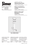
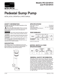
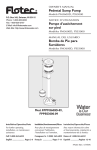
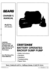
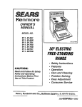
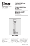
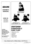
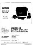
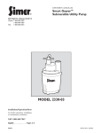
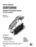
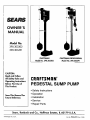
OWNER'S
MANUAL
Model No.
390.303302
390.303491
CRAFTSMAN
Model No. 390.303302
CAUTION:
Read and Follow
All Safely Rulesand
Operating Instructions
Before FirstUse of
This Product.
CRAFTSMANPROFESSIONAL
Model No. 390.303491
CRAFTSMAN+
PEDESTAL SUMP PUMP
• Safety Instructions
Save ThisManual For
Future Reference.
• Operation
• Installation
• Service
• Repair Parts
Sears, Roebuck and Co., Hoffman Estates, IL 60179
PRINTED
IN
U.S.A.
U.S.A.
Form No.
F642-2001
(Rev. 4/19/04)
CONTENTS
Introduction
INTRODUCTION
........................................................................
2
Warranty ..............................................................................
Safety Rules ..........................................................................
Installation
........................................................................
Service .................................................................................
2
2
3-5
5
Repair
6-7
Parts .......................................................................
Please read our instructions
before you install and use your
new pump; this will help you obtain full value and good service from it. It will also help you avoid needless service costs
that result from causes we cannot control and cannot cover
in our warranty.
+
RULES
Carefully
read and follow
manual
or on pump.
FOR SAFE INSTALLATION
all safety
instructions
in this
warns
injury,
death
[&WARNING t warns
personal
injury,
death
[& CAUTION ] warns
minor
personal
The word
important
injury
about
hazards
or major
about
that
property
hazards
that
or major property
about
hazards
or property
will cause
damage
2,
serious
serious
[.&WARNING] Risk
if ignored.
lows
which
atmospheres.
if pmnp
of electric
needs
shock.
motors
Proceed
are de-
as fol-
servicing:
A. Disconnect
power
to pump
outlet
box before
pulling
pump
cord plug! After plug is pulled, let
pump cool for 20 minutes before attempting
to work
on it.
if ignored.
NOTICE indicates special instructions
but not related to hazards.
Check your local Electrical and Plumbing Codes before
installing pump. You must comply with their rules.
Do not touch an operating motor. Modern
signed to run at high temperatures.
that will or can cause
damage
•
OPERATION
['_WARNING_DO not use in explosive
Pump water only with this pump.
if ignored.
can cause
damage
•
1. Read these Instructions
and Safety Rules carefully.
Failure to follow them could cause serious bodily injury
and!or property
damage.
This is the safety alert symboL
When you see this
symbol on your pump or in this manual, look for one of the
following signal words and be alert to the potential
for personal injury!
personal
AND
•
are
Electrically powered
sump pumps normally give many years
of trouble-free
service when correctly
installed, maintained,
and used. However,
unusual circumstances
(interruption
of
power to the pump, dirt/debris
in the sump, flooding that exceeds the pump's capacity, electrical or mechanical
failure in
the pump, etc.) may prevent
your pump from functioning
normally. To prevent possible water damage due to flooding,
consult your local Sears store about installing a secondary
sump pump or a DC backup sump pump. See "Service",
Page 5, for information
about common
sump pump problems and remedies.
B. Take extreme
care when
changing
fuses. To reduce the chance of fatal electrical
shocks, DO NOT
stand in water or put your finger in the fuse socket.
C. Ground
the electrical outlet box.
D.Use
only
a grounded
outlet
for cord plug.
E. Do not handle pump motor with wet hands or when
standing on wet or damp surface, or in water.
3.
NOTICE: This unit is not designed for applications
involving
salt water or brine! Use with salt water or brine will void
warranty.
Never run pump dry. To do so can damage internal parts,
overheat the pump (which can cause burns to people handling or servicing the purnp), and will void the warranty!
[.&WARNING IF IRE HAZARD
- Do not store
or rest ob-
jects on or near motor
or switch
linkage.
Keep
flamLmmble objects
or liquids away from motor.
2
all
PUMP INSTALLATION
4. This pump is recommended
for use in permanent installations only. Do not install on clay, earth, or sand surfaces.
1
A CAUTION j Pump
must
cal) when operating.
switch may overheat
be level
(column
If motor is tilted,
and damage motor.
must
internal
be vertistart/run
ADDITIONAL
INSTALLATION
MATERIALS
SumpFLTtility Pump Hose Kit, SEARS Stock No. 27909, containing 24' of 1-1/4" flexible plastic pipe, a 1-1/4" plastic
adapter and a stainless steel clamp.
Check
Valve, SEARS Stock
No. 2789 or 2792.
THE SUMP
The sump should be located at the lowest place in the basement or area to be drained. Floor drains from other areas in
the basement may be tiled into the sump. Drain tile around
a house foundation can also be tried into the sump, effectively removing water and relieving pressure from this area.
A suitable sump can be a 20" or 24" sewer tile. Sump must
be at least 12" in diameter.
A sump
Consult
cover is desirable
to exclude refuse from the sump.
local code for sump cover specifications.
SPECIFICATIONS
Power
supply
required
....................................
115V, 60 HZ.
Horsepower
(390.303302)
.............................................
1/3
Horsepower
(390.303491)
.............................................
1/2
Motor
duty .........................................................
Liquid Temp.
Individual
Requirement
Range ........................
Branch
Intermittent
Check your local Electrical and Plumbing Codes before installing pump. You must comply with their rules.
Set the pump on the bottom of the sump, making sure that
it sits solidly and is level. Be sure there is enough space
around the pump to allow the switch free movement as
the sump water level changes. Do not install on clay,
earth, or sand.
[A _
Risk of flooding. If a flexible discharge
hose is used, pump may move around in sump
when motor starts. If it moves far enough so that the
switch hits the side of the sump, the switch may stick and
prevent pump from starting. Make sure that pump is secured so that it cannot "walk around" in sump.
NOTE: To avoid backflow into the sump when the pump
shuts off, install a Check Valve, SEARSStock No. 2789, in the
threaded discharge port of pump (390.303302) or 1-1/2"xl1/4" reducer bushing (390.303491). Reducer bushing is included with Model 390.303491. Be sure arrow on check
valve body points away from the pump. This Check Valve is
equipped with an air bleed hole to prevent airlocking the
pump. If using any other check valve, drill 1/8" (3.2 ram)
hole in discharge pipe just above pump body but below
check valve to prevent air locks.
Use 1-1/4" plastic pipe from Hose Kit No. 27909 for the discharge pipe. Run the discharge pipe to the nearest sewer
outlet or other point of disposal. Use the most direct route
with the fewest turns and elbows possible.
Use Teflon tape to seal threads in plastic pipe. Hand tighten
only.
32 ° F to 70 ° F (0°-21°C)
Circuit
20 =to 24"
GFCI Class A ......................................
1/4"
15 Amps
Motor
full load (maximum
- 390.303302)
.............
Motor
full load (maximum
- 390.303491)
............. 7.3 Amps
Sump Cover
\
Basement Floor
3.5 Amps
Discharge
(390.303302)
......................................
1-1/4" NPT
"_ischarge
(390.303491)
......................................
1-1/2" NPT
SewerTile
12" Mm
Sewer Tile , ',',,
20" to 24" Diam.
Figure
I
+
_ g
Concrete
ROD AND FLOAT
SWITCH
INSTALLATION
The switch
2.
float rod into float until it is firmly hand tight.
Slide rod guide over float rod; follow it with a rod stop
bushing (A) set about eight inches down from the top of
the rod.
3.
Slide float rod up through the eye in the switch
a rod stop bushing (B) at the top of the rod.
4.
Open large loop on
column. Fasten with
hangs vertically from
rod guide. Make sure
Adjust rod stop bushings
6.
Lift the rod up and down to be sure the switch
and that the arm does not bind on the rubber
The rod must also move freely in the guide.
7.
Fill the sump and run pump
to check switch operation.
for designed
through
level control.
Switch Arm
When the water rises in the sump, the float lifts the svdtch
rod. The buoyancy will push the switch arm up and turn
the switch on.
3. When the water is pumped out of the sump, the float
drops down again. The weight of the float will allow the
rod and switch arm to lower and turn the drainer switch
off.
DO NOT ALLOW
cycle
Ill
PUMP TO RUN DRY
Pump should not be allowed
To do so voids the warranty
to run dry prior to shutting
and could ruin the pump.
ELECTRICAL
CONNECTIONS
Risk of electric
shock.
The Sump Pump
has a 3-prong
electric
plug. The third prong
is used to
ground
the pump to prevent
possible
fatal shock. The
third prong should
never be removed.
Your electrical
outlet should
be the 3-prong,
polarized
type with an
internal
ground.
DO NOT
Testing
into a 15 amp GFCI protected
USE AN EXTENSION
for Ground
For your safety, check your outlet for ground using a Circuit
Analyzer, (Figure 3). A Circuit Analyzer will tell you by a pattern of lights if the power, neutral, and ground wires are correctly connected
to your outlet. It can also be used to check
other outlets in your home. A Circuit Analyzer is available in
the SEARS Electrical Department.
UL Listed
Analyzer
Rod Guide
Outl_
Figure 3
Figure 2
individ-
CORD.
Sump Cover
Float
off.
adjust the float so this will not happen.
Pump must be wired
ual branch circuit.
III
Float Rod
2.
If necessary,
will click
bushings.
one complete
Rod Sto
Rod Stop (A)
arm. Add
rod guide and mount it around the
screw, making sure that the float rod
the switch and moves freely in the
the rod guide is tightly clamped.
5.
as follows:
1. When the sump is dry, the float rod hangs from the switch
alan. Its weight holds the switch off.
See Figure 2 for stop positions.
1. Thread
unit operates
8650194
Grounding
GENERATOR
Outlet
SIZING
If outlet is not grounded, install a copper wire (at least 14
gauge) from the outlet box, as shown in Figure 4, to a metal
cold water pipe. Use ground clamp on pipe.
Below is the Engine-Generator
Watt rating required
to
power this pump motor. Any additional loads, such as lights,
must be added to the listed load and the generator
sized ac-
IMPORTANT: The cold water pipe you use as a ground
must have metal continuity to electrical ground. If continuity
is interrupted by plastic, rubber, or other electrical insulators; such as hoses, fittings, washers or gaskets (including
water meter or pump), a metal bypass must be used. Any
electrically insulated connector should be jumped (as shown
in Figure 5), with a length of No. 4 wire clamped securely
at both ends.
cordingly.
Pump
Motor HP
Minimum Watt
Rating of Generator
1/3
2,200
1/2
2,800
SERVICE
Outlet
Box
General
AWARNING]Risk
Bare co per wire to
coldwatPe_r
pipe.
6690194
Figure 4
1.
No, 4
Wire
of electric
shock.
When
servicing
pump
always
disconnect
power
to electrical
outlet
and remove
pump
electric
cord from outlet. Inspect
sump pump
and system
components
monthly.
Keep
free of debris
and foreign
objects.
Clamp
If pump
does not operate:
a.
Check
b.
Check for blown fuses or tripped
fuse box/circuit
breaker box.
for loose
plug at electric
outlet.
circuit
breakers
at
c. Be sure nothing interferes with action of float switch.
d. ff a, b, and c above check OK, plug in a light that you
know works, ff it fights, take your pump to SEARS for
service, flit doesn't light, the electrical circuit is faulty;
consult a licensed electrician.
Metal Water
Pipe
Metar
670 01_4
Figure 5
Automatic
Thermal
Overload
2. Pump
Protection
This pump motor has a built:m automatic
thermal overload
protector.
If the motor overheats,
the protector
will open
and cut off power to the motor before the heat damages it
internally.
The overload
will reset automatically
and the
pump will restart after the pump cools down below the danger point.
IA WARNING]DO NOT attempt to work on the pump or
motor if the overload
seems to have tripped. The
motor may restart without warning at any time. You
could be injured and the pump damaged if it starts
when you are working on it.
DO NOT attempt to repair a sump pump. Take it to SEARS
for service by a qualified technician.
starts,
but blows
fuses/trips
circuit
breakers:
After disconnecting
power
to pump, remove
it from
sump. Remove the plate from the bottom of the pump
and make sure that the impeller turns freely. Remove any
debris obstructing
impeller. If pump still does not operate correctly,
return it to your nearest
SEARS Service
Department
for repairs.
3.
Pump
runs, but does not empty
intake
sump:
a.
Clean pump
screen.
b.
Water may be enteO.ng sump
discharge it.
c.
Be sure vertical distance from pump discharge outlet
to discharge
pipe outlet is 18 feet or less for Model
390.303302
(20 feet or less for Model 390.303491).
d.
Be sure discharge
faster than the pump
pipe is not plugged
can
or frozen.
LUBRICATION
Motor has been lubricated
at the factory.
additional
oil. Bronze hearing
in volute
pregnated.
It does not require additional
It does not require
housing
is oil imoil.
Craftsman
Model 390.303302
,,
3
-..
4
9A
6
"-5
659 0594
Key No.
1
2
3
4
5
6
7
8
9
9A
10
11
Part Number
U30-932ZP
RP0005257
RP0005246A
$101-33P
SC004-116
FT0013-63
RP005168S
RP0005249
U30-929ZP
2773
RP0005248
U17-318
• Not illustrated.
** If motor fails, replace entire pump.
Description
Motor with Cord and Switch
Screw #8 x 1/2" Hex Head (2 Required)
Shaft
Column
Impeller Assembly
Screw #8-18 x 3/8 Self Tap
Float
Rod
Rod Guide
Screw #8 x 1" Phillips Head
Switch
Float Stop (2 Required)
Cord and Plug
Craftsman Professional
Model 390.303491
13
10
1
2
12
3
4
I
6
I
7
27121196
Key No,
1
2
3
4
5
6
7
8
9
9A
10
11
12
13
Part Number
Description
Motor with Cord and Switch
U30-946PH
RP0005257
$15-37SS
$1-32B
$5-13P
PS4-17P
U30-571BT
RP0005249
U30-929ZP
RP0005248
FT0013-63
RP005168S
2773
U17-318
U78-130P*
Set Screw (4 Required)
Shaft
Column
Volute
impeller
Base Plate
Screw #8-32 x 1/2 Hex Head (8 Required)
Rod Guide
Screw #8xl" Phillips Head
Rod Bushing (2 Required)
Float
Rod
Switch
Cord and Plug
1-1/2" x 1-1/4" Reducer Bushing
• Not illustrated
* May be purchased locally.
** If motor fails, replace entire pump.
"7
SEARS
OWNER'S
MANUAL
I:RRFTSMRN°
PEDESTAL SUMP PUMP
Model No.
390.303302
390.303491
Forthe repair or replacementpartsyou need
Call7 am - 7 pm, 7 daysa week
1-800-366-PART
(1-800-366-7278)
Forin-homemajorbrandrepairservice
Call24 hours a day, 7 days a week
The model number of
1-800-4-REPAIR
(1-80D-473-7247)
your PedestalSump Pump
will be located on the side
of the motor.
When requesting service
or ordering parts, always
give the following
information:
• Product Type
• Model Number
• Part Number
• Part Description
Forthe locationof a
SearsRepairServiceCenterin yourarea
Call24 hours a day,7 daysa week
1-800-488-1222
Forinformationonpurchasinga Sears
MaintenanceAgreementor to inquire
aboutan existingAgreement
call 9 am - 5 pm, Monday-Saturday
A
,_SSARS
1-800-827-6655
SEARS
Arner_.a's Repair SpecJalists
Sears, Roebuck and Co., Hoffman Estates, IL 60179
U.S.A.