1
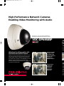
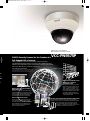
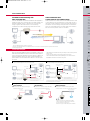
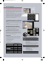
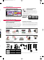
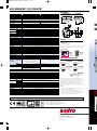
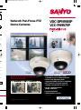
45.5 (1.8)
115.5 (4.5)
nch)]
Network Pan-Focus PTZ
Dome Cameras
VDC-DPN9585P
VCC-PN9575P
a unit.
only).
-70
ra
l unit
75PA
ni
mera
575P
ni PTZ
mera
200P
roof
mera
ehe
tium
r
their
Network Indoor Mini
Dome Camera
Network Vandal-Resistant
Day/Night Dome Camera
VCC-PN9575P
VDC-DPN9585P
e
t;
cifi-
Built-in X2.6 Motorized Zoom
Pan-Focus Lens
(f = 2.8–7.3 mm, F = 1.9–3.0) No focus adjustments
Pan-focus lens image
Varifocal lens image
• Networked Surveillance with
Two-Way Voice Communications
• Power-over-Ethernet (PoE)
Supported (IEEE 802.3af Compliant)
• PTZ Control & Remote Camera
Setting via Network or VAC-70
• 25 IPS, High-Resolution
Image Selection
• Vandal-Resistant *
• IP66 Rated Enclosure *
*VDC-DPN9585P
Comparative images are representations only.
The products introduced here are manufactured in Japan
utilizing advanced technologies and quality control.
High-Performance Network Cameras
Enabling Video Monitoring with Audio
Network 1/4” Color CCD DSP High-Resolution
Day/Night Vandal-Resistant PTZ Dome Camera
VDC-DPN9585P
SA
Fu
Vide
VAsoft
from
live
* Use
netwo
camer
Wide Area Surveillance with a x2.6
Pan-Focus Lens and PTZ Control
Deep focus technology brings every area on-screen
into crisp and clear focus for a precise picture with
greater depth of field. In addition to the pan-focus
lens developed by SANYO, VDC-DPN9585P and VCCPN9575P cameras feature pan-tilt-zoom (PTZ)
functions allowing remote control over a network for
surveillance of wide areas.
• Clear focus on entire
viewing area with
great depth of field
• No focus adjustments
• Remote zoom
adjustment via
Network or VAC-70
Digi
Netw
Pan-focus lens image
• Clear focusing on
a specific area
• Manual focus
adjustments
• Manual zoom
adjustments
Varifocal lens image
Imag
ing v
miss
ens t
and
Alar
Whe
ted,
from
alarm
be se
sent
Network 1/4” Color CCD DSP
High-Resolution PTZ Dome Camera
VCC-PN9575P
SANYO Security Systems for the Creation of a
Full-fledged LAN or Internet
Video captured by camera can be viewed using the bundled
VA-SW3050LITE viewer software. Use of the VA-SW3050 archiving
software (sold separately) allows simultaneous monitoring of streams
from up to 128 cameras as well as recording of
live audio and video data.
* Use of the VDC-DPN9585P’s or the VCC-PN9575P’s built-in
networking features allows viewing of video from a single
camera with a generic web browser (Internet Explorer).
ire
d
ents
I
0
Digital Image Processing Suited to
Networked Output
Image processing of JPEG images offering versatility has been adopted for transmission of high-quality images. This lightens the burden placed on the network
and increases precision in surveillance.
N
T
E
R
N
E
T
Networked Centralized Control
of Data from a Variety of
Surveillance Points
Management of video from surveillance points under a variety of conditions — whether outdoors, at remote locations, or at night — can
be consolidated at a PC in a control
center. This enables efficient operation of 24/7 systems and broadbased surveillance for retail outlets
or large-scale facilities.
Alarm Notification Functions
Two-Way Voice Transmissions between Camera and PC
When a potential security threat is detected, a single surveillance video image
from that moment is sent by email as an
alarm notification. Email addresses can
be set in advance so that notification is
sent to up to five locations.
Two-way communications inclusive of voice exchanges
between a control room and surveillance points allow instructions issued from the control room to surveillance points while viewing images sent from
cameras or, conversely, voicing of opinions from
surveillance points to the control room.
Voice Communications
Netw
VDC-DPN9585P/VCC-PN9575P
VA-
Surveillance-Point Monitoring with
Video and Audio Data
Audio Transmission from
Control Center PC to Surveillance Point
The VDC-DPN9585P and the VCC-PN9575P are equipped to
enable two-way voice communications via audio signals sent
between cameras and PCs. Transmission of crystal clear
images together with audio offers those overseeing
surveillance as a sense of being right there at the scene.
Audio transmissions can be sent from the administrator’s side
to the camera so as to provide advice or cautionary notices in
the event of unaccounted for activity and other events during
surveillance. Voice exchanges with personnel at surveillance
points not only enable a more accurate grasp of the situation
but also serve to prevent crimes or accidents.
Monitor
Speaker
Camera
Video and Audio Data
The
VA-S
sent
also
eras
agem
VA-S
answ
capt
VA-S
cord
pow
Audio Data / Power Supply* / Mechanical Control
Speaker
S
LAN cable
Microphone
PC
Microphone
• The VCC-PN9575P features a built-in microphone.
• Both the VDC-DPN9585P and the VCC-PN9575P can be connected to external microphones, speakers and monitors.
* Power adapter required.
*CPU
Pictu
Connection Examples
Both the VDC-DPN9585P and the VCC-PN9575P support the
IEEE 802.3af standard for Power-over-Ethernet (PoE) applications to allow power supplied over LAN cabling. In addition to
making installation easier, this allows camera installation in
places where it would otherwise be difficult to secure a power source.
PoE Example 1:
• LAN cable types required will vary according to the switching hub or
router used.
• Do not use the camera’s power supply when using PoE.
• The VA-50H heater board (sold separately) for use with the VDCDPN9585P cannot be used when using PoE.
Use of PoE Supported Switching Hub
LAN Cable (Straight Type)
Up to 100 Meters
LAN Cable (Straight Type)
Up to 100 Meters
Switching Hub
Speaker
Audio Output
(3.5 mm Mini Jack)
Speaker
Speaker
Video Output
(BNC Connector)
TV Monitor
Up to 100 Meters
Video Output
(BNC Connector)
Microphone
Audio Output
(3.5 mm Mini Jack)
Speaker
Oth
Microphone
Video/Audio Data
+ Power Supply
External Mic Intput
(3.5 mm Mini Jack)
Microphone
External Mic Intput
( 3.5 mm Mini Jack)
Audio Sent to Camera Side
Audio Confirmed on PC Side
Audio Sent to Camera Side
• Longer transmission distances are possible than those using a power adapter
and a switching hub as in example 1.
Audio Confirmed on PC Side
Reco
simu
diffe
ty to
to m
PC
LAN Cable (Straight Type)
Video/Audio Data + Power Supply
Microphone
PoE Supported
Switching Hub
PC
PoE Supported
Adapter
S
Sett
each
ing,
S
PoE Example 2:
Use of Power Adapter and Port-Switching Hub
TV Monitor
VA-S
data
reco
with
• Dis
• Sim
• Fle
• Ea
• Tim
• Ala
• Tim
Example of Use without PoE
VA-S
Basic Connection
LAN Connection
Internet Connection
Connection by LAN cabling (crossed type)
between camera and PC.
Connection of camera to LAN by LAN cable
(straight type) using switching hub, etc.
Connection of camera and router by LAN cable
or ADSL modem, etc. when used for LAN connection.
Router or ADSL Modem
Switching Hub
LAN Cable
(Crossed Type)
LAN Cable
(Straight Type)
PC
Internet
LAN
AC Adapter
AC Adapter
Num
Num
Sea
Live
Cam
AC Adapter
• Router connected using straight type cabling.
• Confirm connection method when connecting
an ADSL modem or other device.
• Please use a type of LAN cabling that is shielded.
Reco
Play
Vide
Back
Dow
Network Archiving Software
VA-SW3050 (Sold separately)
de
n
g
e
n
The VDC-DPN9585P and the VCC-PN9575P are bundled with
VA-SW3050LITE viewer software allowing live video streams
sent from cameras to be monitored on a PC. This software
also supports audio transmissions and remote control of cameras, making it excellent for smooth configuration and management of surveillance systems.
Main window
VA-SW3050 network archiving software is sold separately in
answer to needs for archiving of surveillance video and audio
captured by cameras. With a PC used as a local server, the
VA-SW3050 software enables not only data playback and recording but also improved system operability, making it a
powerful tool for network management.
Simultaneous Recording from Up to 128 Cameras
VA-SW3050 software simultaneously records video and audio
data from up to 128 cameras. High-resolution images are
recorded at a rate of 25 IPS* for smooth playback comparable
with television.
Camera layout setting
*CPU: Pentium 4, 3.06 GHz or higher, Memory: 512 MB RAM
Picture setting: BASIC, Picture size: 720 x 286, Single camera connection
or
e
ter
on.
Surveillance Camera Control via Network
Setting of camera IDs allows precise condition setting for
each surveillance point. Also enabled is control of panning, tilting, zooming and other camera functions.
Camera control
Simultaneous Access by Up to 16 Users
Recorded video and audio can be accessed by up to 16 users
simultaneously. User access is managed by password to
differentiate those at the administrator level, with the authority to alter settings, and those at the user level, with the right
to monitor surveillance video and audio.
Other Features
• Display switching between full, quad or 16 split screen
• Simultaneous playback and recording of video and audio
• Flexible settings with a wide array of recording modes
• Easy-to-use graphical interface
• Time data search function
• Alarm search function
• Timer recording
VA-SW3050LITE/VA-SW3050 Feature Comparison
VA-SW3050LITE VA-SW3050
(Bundled)
(Sold separately)
Number of cameras supported
Max. 128
Max. 128
Number of users supported
Max. 16
Max. 16
Search camera
Yes
Yes
Live monitor
Yes
Yes
Camera control PTZ, etc.
Yes
Yes
Yes
Yes
Menu
Recording
No
Yes
Playback
No
Yes
Video search
No
Yes
Backup/Restore
No
Yes
Download/Print
No
Yes
16-screen display
VA-SW3050LITE/VA-SW3050 System Requirements
PC
OS
CPU/
Memory
IBM PC/AT and compatibles
Windows® 2000 Professional SP4, Windows® XP Home Edition
SP2, Windows® XP Professional SP2
When the number of cameras connected is 4 or fewer:
CPU: Pentium® 4, 2.0 GHz or higher, Memory: 512 MB or more
When the number of cameras connected is between 5 and 16:
CPU: Pentium® 4, 3.0 GHz or higher, Memory: 1 GB or more
MEMO (VA-SW3050):
When you record live video from 17 or more cameras simultaneously on a single PC, recording performance may be diminished
depending on your monitoring system configuration. In such
cases, add PCs used for recording so that the number of cameras
to record simultaneously per PC becomes 16 or fewer.
Network
100Base-TX
interface
Display card 1024 x 768 pixels or higher, 16 million colors or higher
AGP graphics card supporting hardware overlay
or PCI Express graphics card (Requires the latest DirectX 9.0c
compatible driver.)
Recommended graphics chip
ATI: RADEON 9000 series or higher
nVidia: GeForce 4 series or higher
Quadro 4 series or higher
Matrox: MillenniumP series or higher
Sound card and speakers with 100% DirectX compatibility
Audio
Component DirectX 9.0c
Functions Specific to the
Fun
VDC-DPN9585P/VCC-PN9575P
VDC
Intelligent Backlight Compensation
Inte
Pro
inf
Lx
The VDC-DPN9585P and VCC-PN9575P feature two selectable
backlight compensation modes: multi-spot metering (applied to
the whole screen) and center-zone metering (applied to the
central portion only).
Multi-spot metering measures luminous intensity in 64 areas on screen to enable
optimal backlight compensation even for peripheral and moving objects.
Flexible Motion Detection
16 Preset Positioning and
Sequential Monitoring
Functions
Up to 16 preset positions (with
different settings for pan, tilt and
zoom) can be registered for a
single VDC-DPN9585P or VCCPN9575P. A simple key entry to
a controller allows you to easily switch to the scene you want to
monitor. Auto-pan monitoring can be also be programmed by
designating two end points on a horizontal plane.
Sensing is performed by splitting the field of view into 16
areas. Movement and brightness levels within the picture are
analyzed to accurately detect surveillance targets. Upon detection, the camera sends an alarm status signal and captures the
object at zoom magnifications of up to x2.6. Fine adjustments
of settings such as sensitivity, tracking time, zoom ratio and
areas not requiring detection can also be made.
x2.6
PTZ Operations
Both the VDC-DPN9585P and VCC-PN9575P come with a PT
mechanism and allow panning of 335 degrees (110 degrees*)
and tilting of 90 degrees (90 degrees*) to reduce blind spots in
the surveillance area. When particular angles are preset on the
camera (up to sixteen points), it moves to each position quickly at the speed of 120 deg/sec. max. for both panning and tilting. Combining these features with the motion detector, it is
possible to catch all actions taking place in the area.
*For wall-mounted cameras
Photos of VDC-DPN9585P
Ceilling mounting
Panning
0 to 335°
Tilting
0 to 90°
Wall mounting
Panning
–55 to 55°
Tilting
0 to –90°
Adjustment via VAC-70 Control Unit (Sold Separately)
Connection of the VAC-70 control unit allows adjustment of
pan/tilt, angle of view, motion detector, backlight compensation and other functions from in front of a monitor. The lens
angle can be adjusted directly via a control
switch inside the camera housing.
Video coaxial cable
VDC-DPN9585P
Control switch
inside camera
B
m
Swit
mon
also
from
Use
VDC
Inst
Sim
Base
the r
enha
and
abilit
and
Mou
Areas with swaying trees or flickering light, etc. can be eliminated to avoid false
alarms. Surveillance of the detected object can be conducted at a zoom magnification
of x1.0, x1.4, x2.0 or x2.6.
The p
Pleas
Privacy Masking (Up to 8
Masks)
When there is a house or even
an object as small as a window
within the camera frame, it is
possible to mask the area so that
it will not appear on the monitor
screen to protect other’s privacy.
Up to 8 rectangular masks of arbitrary size can be set. These
masking areas may be protected with a 4-digit (max.) password.
520 TV Line Resolution (Analog Video Signal)
Featuring SANYO’s DSP circuitry and a high performance 1/4inch CCD for horizontal resolution of more than 520 TV lines
and superior color reproduction. Sharp, crisp images are
delivered for greater precision in surveillance under a varied
range of conditions.
The c
can b
by sim
In the
Pu
Hold
detac
Mou
Atta
VA-
8.0
Built-in Electronic Shutter
42.0
(1.65)
A high-speed electronic shutter that is internally switchable for
eight modes using a DIP switch allows adjustment increments
from 1/50 to 1/10,000 sec.
46.0
(1.81)
Operation on PoE, AC or DC Power Sources
VAC-70
Monitor
The VDC-DPN9585P and VCC-PN9575P can operate on PoE,
12 V DC (12–15V DC) or 24 V AC (50 Hz, and even at a tolerance of ±10%). Switching to the correct mode occurs automatically when power is supplied.
Mod
VDC
VCC
re
ecthe
ts
VDC-DPN9585P
Intelligent Switching from Color to B/W
Proprietary auto-switching
infrared cut filter
B/W
mode
Tough Die-Cast Aluminum with
Polycarbonate Dome
Housed in an exceptionally tough die-cast
aluminum enclosure and a polycarbonate
dome for extra durability under the most demanding of conditions. To protect against tampering, the screws of the enclosure cover have a unique shape that prevents it from being
opened with ordinary tools.
Switchover point
3~9 lx
Color mode IR cut filter ON
Lx
ble
d to
Functions Specific to the
B/W
mode
High mode
1~3 lx
Low mode
(Approx.)
Time
B/W mode
IP66 Rated Weatherproof Design
Color mode
Switching between color mode during daylight hours and
monochrome at night is done automatically (manual switching
also possible). Selection of switching settings can be made
from a range of 1 to 10 lx.
High Sensitivity,
Minimum Required
Illumination
B/W mode
Color mode
Gain: High
Gain: High
0.024 lx
0.06 lx
0.48 lx
1.2 lx
(F1.9, 20 IRE)
(F1.9, 50 IRE)
User-Friendly Design and Easy Setup
VDC-DPN9585P/VCC-PN9575P
Installation, Setup and Operation Made Easy by
Simple, User-Friendly Design
Easy Interior Access and Setup
Inside the housings of the VDC-DPN9585P and VCC-PN9575P
are camera units with integrated motors and lenses. Installation
on ceilings or walls can be accomplished without difficulty and
components such as the camera unit or an optional heater
board* can be attached and detached easily in just a few steps.
Based on a development concept featuring a pan-focus lens for
the realization of advanced surveillance functions together with
enhanced operability and ease of installation. The VDC-DPN9585P
and VCC-PN9575P increase lens function and camera maneuverability to simplify operation, save resources spent in installation
and substantially heighten the available degree of freedom.
*The heater board option can be mounted only in the VDC-DPN9585P.
Mounting and Installation
The product pictured below is the VDC-DPN9585P. Specifications differ slightly in the case of the VCC-PN9575P.
Please refer to the operating instructions supplied with each product for details.
tion
The camera unit and board
can be attached or detached
by simply sliding the stopper.
Wall mounting
Note: In the case of a wall mounted setup, hold down the clamp and
release the hooks, then lift the camera unit and turn it 90° to attach it.
Push
Bottom
cover
Base
plate
Ceilling mounting
Hold down the button on the side of the housing and
detach the base plate from the back of the camera.
Set up and adjust according
to the installation site.
Installation is completed by simply
attaching the camera to the base plate.
Mounting Brackets (Options)
45.5
(1.79)
83.4
(3.28)
0.3 (0.01)
Model name
VDC-DPN9585P
VCC-PN9575P
Installation
Wall mounting
Long ceiling mounting
Short ceiling mounting
Wall mounting
Long ceiling mounting
Short ceiling mounting
M6 *6-2
6 (0.24)
M24 *P-1.5
83.5 (3.29)
6 (0.24)
ø7–4 (0.28–0.16)
6 (0.24)
M24 *P-1.5
83.5 (3.29)
6 (0.24)
M24 *P-1.5
Attachment + Brackets
VA-50AL
+ VA-50BW
VA-50AL
+ VA-50BPL
VA-50AL
+ VA-50BPS
VA-50AS
+ VA-50BW
VA-50AS
+ VA-50BPL
VA-50AS
+ VA-50BPS
Maximum Length
464 ±6 (18.27 ±0.24)
22.8
(0.90)
22.8
(0.90)
205 (8.07)
M6 *6-2
6 (0.24)
83.5 (3.29)
41.7 (1.64)
6 (0.24)
R18.7 (0.74)
ø150 (5.91)
Minimum Length
300 ±3 (11.81 ±0.12)
<M25 15>
66.7
(2.63)
4.5 (0.18)
M6 *6-2
46.0
(1.81)
93°
R154.9
(6.10)
R151.9
(5.98)
ø120 (4.72)
ø120 (4.72)
ø120 (4.72)
Minimum Length
440 ±3 (17.32 ±0.12)
82.5
(3.25)
167.3 (6.59)
162.8 (6.41)
3.4 (0.13)
M4 8 4
Ceiling suspension bracket
VA-50BPL
VA-50BPS
209 (8.23)
22.4 (0.88)
0.5
(0.02)
22.4 (0.88)
42.0
(1.65)
Wall mounting bracket
VA-50BW
Maximum Length
1020 ±6 (40.16 ±0.24)
8.0 (0.31)
Attachment
VA-50AS (for VCC-PN9575P)
209 (8.23)
Attachment
VA-50AL (for VDC-DPN9585P)
for
nts
E,
-
Set up and adjust according to the installation site.
In the case of the VCC-PN9575P
ord.
4-
Attach the camera unit to the bottom
cover mounted at the surveillance
point (ceiling or wall).
66.7
(2.63)
ø7–4 (0.28–0.16)
ø120 (4.72)
66.7
(2.63)
ø120 (4.72)
[Unit: mm (inch)]
Note: Attachments and brackets presented are for indoor use.
In cases of outdoor use, measures must be implemented to ensure waterproofing.
VDC-DPN9585P / VCC-PN9575P
Dimensions
[Unit: mm (inch)]
VDC-DPN9585P
VCC-PN9575P
ø150.6 (6.0)
ø162.0 (6.5)
115.5 (4.5)
35.0
(1.4)
114.8 (4.6)
5.0 (0.2)
ø99.8 (4.0)
R2.5
8.0 (0.3)
2–ø4.3
88.0 (3.5)
46.0
(1.8)
82.5 (3.2)
VDC-DPN9585P
VCC-PN9575P
Model No.
NTSC standard 625 lines, 50 fields/sec.
Scanning system
1/4” Interline transfer method CCD (3.6 x 2.7 mm)
Image sensor
Total: 759 (H) x 596 (V), Effective: 752 (H) x 582 (V)
Number of pixels
More than 520 TV lines (Analog video signal)
Horizontal resolution
Auto (low/high)
Day/Night mode
—
Color, B/W: external control
Minimum illumination
Gain
high:
1.9 lx (F1.9)
50
IRE
(approx.)
Gain high: 1.2 lx (f1.9, color mode) 0.06 lx (B/W mode)
1.0 Vp-p/75 ohms, composite, BNC
Video output
More than 50 dB (AGC Off)
Video S/N ratio
Built-in motorized zoom pan-focus auto iris lens, f = 2.8–7.3 mm (x2.6), F1.9 –3.0
Lens
Focus range: 1 m – ∞
Depth of field
Pan: 0–335 degrees, Tilt: 0–90 degrees
Ceiling
Pan/tilt range
Pan: ±55 degrees, Tilt: 0–90 degrees
Wall
Max. 120 degrees/sec.
Preset
Pan/tilt speed
5–100 degrees/sec.
Manual
On screen display, password lock possible
Menu
16
Preset positions
Sequential pan / Auto pan
Auto mode
On (multi-spot metering [High/Normal], center-zone metering) / Off
Backlight compensation
ATW / AWC / Manual (MWB) / Indoor (3200) / Outdoor (5600) / Fluorescent (FLUO)
White balance
High / Normal / Off
Gain control
1/50, 1/120, 1/250, 1/500, 1/1000, 1/2000, 1/4000, 1/10000 sec.
Electronic shutter
0.45 / 1
Gamma
High plus / High / Normal / Off
Aperture compensation
Internal synchronization / Line lock
Synchronizing system
On / Off, up to 16 characters, title position adjustable
Camera title
On / Off: Max. 8 masked locations
Privacy masking
External x 2, NO / NC selectable, Alarm preset function, Alarm zoom function
Alarm input
External x 1, NO / NC selectable
Alarm output
On / Off: Motion zoom function
Motion detector
Simplified controller (VAC-70: separately ordered) supported
Communications
G. 711 (192 Kbps), full duplex
Audio compression method
-62 to -32 dB (monaural microphone) 3.5mm mini jack
Microphone input
LINE OUT monaural audio output, maximum -8 dB, 3.5mm mini jack
Audio output
IP66
Weatherproof standard
—
-10 to +50°C (14 to 122°F)
-30 to +50°C (-22 to +122°F)
Temperature
-10 to +40°C (14 to 104°F)
Operating
When heater (VA-50H: option board) is used
environment
with power source connected
Humidity
Less than 90% RH (no condensation)
Power supply
24 V AC ±10%, 50Hz or 12–15 V DC, supplied through PoE (compliant with IEEE 802.3af)
Power consumption (approx.)
10 W
Max. 15.5 W
10 W
When heater (VA-50H: option board) turned on
650 g
Weight (approx.)
1520 g
JPEG
720 x 286, 640 x 480 (disabled during voice communications), 360 x 286, 180 x 143
5 levels
Max. 25 IPS (720 x 286)
G.711 (192 Kbps), full duplex
-62 to -32 dB (monaural microphone) 3.5mm mini jack
—
Internal or external selected
LINE OUT monaural audio output, maximum -8 dB, 3.5mm mini jack
128, 256, 512 Kbps, 1, 2, 3, 4 Mbps, no limitation
Up to 8 MB; configurable
10BASE-T/100BASE-TX (RJ45 connector)
Compliant with IEEE 802.3af
TCP, UDP, HTTP, HTTPS, SMTP, NTP, DHCP, FTP, UPnP
Image: Maximum 16, Voice: Maximum 16 (admin: 1)
BASIC authentication (ID/password), SSL supported (image only)
VA-SW3050LITE
Ne
Do
32.0
(1.3)
88.0 (3.5)
83.4 (3.3)
Options (sold separately)
VA-50H
Heater board
for VDC-DPN9585P
Heater board providing protection from cold for camera unit.
Allows use in –30°C operating environments (24 V AC only).
VCZ-50
VAC-70
Smoked type
dome cover
for VCC-P9574N
Camera
control unit
Pan-Focus Camera Lineup
1/4" Color CCD DSP High-Resolution
VDC-DP7585P
VCC-P7575PA
Vandal-Resistant
Day/Night
Dome Camera
Indoor Mini
Dome Camera
VDC-DP9585P
VCC-P9575P
Vandal-Resistant
Day/Night PTZ
Dome Camera
Indoor Mini PTZ
Dome Camera
Network
Image compression
Resolution
Picture quality
Frame rate
Audio compression method
Input
Microphone External
Internal
Audio output
Bandwidth
Alarm buffer
Interface
PoE support
Protocols
Simultaneous access capacity
Security
Bundled software
45.5 (1.8)
Specifications
VCC-XZ200P
Weatherproof
Day/Night
Zoom Camera
Microsoft and Windows are either registered trademarks or trademarks of Microsoft Corporation in the
United States and/or other countries. Intel and Pentium
are trademarks or registered trademarks of Intel
Corporation or its subsidiaries in the U.S. and other
countries. All other trademarks are the property of their
respective owners.
Note:
• Frame rates variable dependant upon network line
conditions and PC performance.
• Because products and software described in this
brochure are subject to continuous improvement;
SANYO reserves the right to modify product specifications, functions and design without notice.
Bu
Pa
(f = 2.
Caution: Please consult the instruction manual to ensure safe and proper operation of the product.
EC00J0303
051
DI Company of SANYO Electric Co., Ltd.
obtained Quality Management System
ISO 9001 and Environmental Management
System ISO 14001 certifications.
Distributed by:
Pan-f
SANYO Electric Co., Ltd.
www.sanyosecurity.com
©2006 SANYO Printed in Japan ’06.9. MA.
SMS132
Comp