1
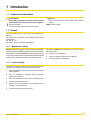
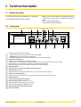
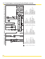
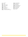
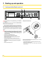
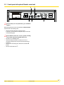
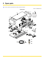
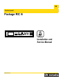
EN
Control panel
Package RC 6
30
0
M000134
l
Installation and
Service Manual
300023031-001-A
Contents
1
Introduction . . . . . . . . . . . . . . . . . . . . . . . . . . . . . . . . . . . . . . . . . . . . . . . . . . . . . . . . . . . . . . . . . . . . . . . . . . . . .3
1.1
1.2
Symbols and abbreviations . . . . . . . . . . . . . . . . . . . . . . . . . . . . . . . . . . . . . . . . . . . . . . . . . . . . . . . . . . . . . . . . . . . . . . . . . . . . . . . .3
General. . . . . . . . . . . . . . . . . . . . . . . . . . . . . . . . . . . . . . . . . . . . . . . . . . . . . . . . . . . . . . . . . . . . . . . . . . . . . . . . . . . . . . . . . . . . . . . .3
1.2.1
Manufacturer's liability . . . . . . . . . . . . . . . . . . . . . . . . . . . . . . . . . . . . . . . . . . . . . . . . . . . . . . . . . . . . . . . . . . . . . . . . . . . . . .3
1.2.2
Installer's liability . . . . . . . . . . . . . . . . . . . . . . . . . . . . . . . . . . . . . . . . . . . . . . . . . . . . . . . . . . . . . . . . . . . . . . . . . . . . . . . . . .3
1.3 Directive 97/23/EC . . . . . . . . . . . . . . . . . . . . . . . . . . . . . . . . . . . . . . . . . . . . . . . . . . . . . . . . . . . . . . . . . . . . . . . . . . . . . . . . . . . . . . .4
1.4 Safety instructions and recommendations . . . . . . . . . . . . . . . . . . . . . . . . . . . . . . . . . . . . . . . . . . . . . . . . . . . . . . . . . . . . . . . . . . . . .4
2
Technical description . . . . . . . . . . . . . . . . . . . . . . . . . . . . . . . . . . . . . . . . . . . . . . . . . . . . . . . . . . . . . . . . . . . . .5
2.1
2.2
2.3
3
General description . . . . . . . . . . . . . . . . . . . . . . . . . . . . . . . . . . . . . . . . . . . . . . . . . . . . . . . . . . . . . . . . . . . . . . . . . . . . . . . . . . . . . .5
Control panel . . . . . . . . . . . . . . . . . . . . . . . . . . . . . . . . . . . . . . . . . . . . . . . . . . . . . . . . . . . . . . . . . . . . . . . . . . . . . . . . . . . . . . . . . . .5
Operating principle . . . . . . . . . . . . . . . . . . . . . . . . . . . . . . . . . . . . . . . . . . . . . . . . . . . . . . . . . . . . . . . . . . . . . . . . . . . . . . . . . . . . . . .6
2.3.1
Boiler regulation . . . . . . . . . . . . . . . . . . . . . . . . . . . . . . . . . . . . . . . . . . . . . . . . . . . . . . . . . . . . . . . . . . . . . . . . . . . . . . . . . . .6
Electrical connections . . . . . . . . . . . . . . . . . . . . . . . . . . . . . . . . . . . . . . . . . . . . . . . . . . . . . . . . . . . . . . . . . . . .6
3.1
3.2
Terminal block . . . . . . . . . . . . . . . . . . . . . . . . . . . . . . . . . . . . . . . . . . . . . . . . . . . . . . . . . . . . . . . . . . . . . . . . . . . . . . . . . . . . . . . . . .7
Installation with optional Rematic control unit. . . . . . . . . . . . . . . . . . . . . . . . . . . . . . . . . . . . . . . . . . . . . . . . . . . . . . . . . . . . . . . . . . .8
3.2.1
Fitting the Rematic control unit. . . . . . . . . . . . . . . . . . . . . . . . . . . . . . . . . . . . . . . . . . . . . . . . . . . . . . . . . . . . . . . . . . . . . . . .8
3.2.2
Connections . . . . . . . . . . . . . . . . . . . . . . . . . . . . . . . . . . . . . . . . . . . . . . . . . . . . . . . . . . . . . . . . . . . . . . . . . . . . . . . . . . . . . .9
3.2.3
Mouting of the control unit . . . . . . . . . . . . . . . . . . . . . . . . . . . . . . . . . . . . . . . . . . . . . . . . . . . . . . . . . . . . . . . . . . . . . . . . . .11
3.3 Connecting a third party control unit. . . . . . . . . . . . . . . . . . . . . . . . . . . . . . . . . . . . . . . . . . . . . . . . . . . . . . . . . . . . . . . . . . . . . . . . .12
3.4 Connecting the burner alarm indicator . . . . . . . . . . . . . . . . . . . . . . . . . . . . . . . . . . . . . . . . . . . . . . . . . . . . . . . . . . . . . . . . . . . . . . .12
3.5 Connecting the low-water pressure switch alarm indicator (Only NL) . . . . . . . . . . . . . . . . . . . . . . . . . . . . . . . . . . . . . . . . . . . . . . .13
3.6 Connecting the safety thermostat alarm indicator . . . . . . . . . . . . . . . . . . . . . . . . . . . . . . . . . . . . . . . . . . . . . . . . . . . . . . . . . . . . . .13
3.7 Connecting the outlets "boiler run" and "burner alarm" . . . . . . . . . . . . . . . . . . . . . . . . . . . . . . . . . . . . . . . . . . . . . . . . . . . . . . . . . .13
3.8 Connecting one or two hour run meters (Package BG 40). . . . . . . . . . . . . . . . . . . . . . . . . . . . . . . . . . . . . . . . . . . . . . . . . . . . . . . .14
3.9 Connecting the flue gas thermometer (Package BP 28) . . . . . . . . . . . . . . . . . . . . . . . . . . . . . . . . . . . . . . . . . . . . . . . . . . . . . . . . .15
3.10 Connecting the burner . . . . . . . . . . . . . . . . . . . . . . . . . . . . . . . . . . . . . . . . . . . . . . . . . . . . . . . . . . . . . . . . . . . . . . . . . . . . . . . . . . .15
3.10.1 Burner without plug-in connectors . . . . . . . . . . . . . . . . . . . . . . . . . . . . . . . . . . . . . . . . . . . . . . . . . . . . . . . . . . . . . . . . . . . .16
3.10.2 If the electrical characteristics of the burner exceed the following values:. . . . . . . . . . . . . . . . . . . . . . . . . . . . . . . . . . . . . .16
4
Skeleton Diagrams . . . . . . . . . . . . . . . . . . . . . . . . . . . . . . . . . . . . . . . . . . . . . . . . . . . . . . . . . . . . . . . . . . . . . .17
4.1
4.2
5
Starting up and operation. . . . . . . . . . . . . . . . . . . . . . . . . . . . . . . . . . . . . . . . . . . . . . . . . . . . . . . . . . . . . . . . .20
5.1
5.2
6
Principle diagram of the control panel . . . . . . . . . . . . . . . . . . . . . . . . . . . . . . . . . . . . . . . . . . . . . . . . . . . . . . . . . . . . . . . . . . . . . . .17
Principle diagram of control panel with optional Rematic control unit. . . . . . . . . . . . . . . . . . . . . . . . . . . . . . . . . . . . . . . . . . . . . . . .18
Control panel without Rematic control unit . . . . . . . . . . . . . . . . . . . . . . . . . . . . . . . . . . . . . . . . . . . . . . . . . . . . . . . . . . . . . . . . . . . .20
Control panel with optional Rematic control unit. . . . . . . . . . . . . . . . . . . . . . . . . . . . . . . . . . . . . . . . . . . . . . . . . . . . . . . . . . . . . . . .21
Spare parts. . . . . . . . . . . . . . . . . . . . . . . . . . . . . . . . . . . . . . . . . . . . . . . . . . . . . . . . . . . . . . . . . . . . . . . . . . . . .22
Control panel RC6
06/01/10 - 300023031-001-A
1 Introduction
1.1 Symbols and abbreviations
Caution danger
Reference
Risk
ZRefer
of injury and damage to equipment. Attention must be
to another manual or other pages in this instruction
paid to the warnings on safety of persons and equipment.
manual.
DHW: Domestic hot water
Specific information
Information must be kept in mind to maintain comfort.
1.2 General
The control panel is fitted on P 520, P 420 and P 320 boilers from
Remeha.
This product will be marketed in the following European Union
member states:
BE - GB - NL - HU
with a gas or oil-burner of the associated category.
1.2.1
Manufacturer's liability
Remeha manufactures products in compliance with the standard 1.
Products are delivered with 1 marking and all documents required.
The liability of Remeha as the manufacturer may not be invoked in
the following cases:
In the interest of customers, Remeha are continuously endeavouring
to make improvements in product quality. All the specifications stated
in this document are therefore subject to change without notice.
`
Incorrect use of the appliance,
`
Faulty or insufficient maintenance of the appliance,
`
Incorrect installation of the appliance.
1.2.2
Installer's liability
The installer is responsible for the installation and inital start up of the
appliance. The installer must respect the following instructions:
`
Read and follow the instructions given in the manuals provided
with the appliance.
`
Carry out installation in compliance with the prevailing
legislation and standards.
`
Perform the initial start up and carry out any checks necessary.
`
Explain the installation to the user.
`
Warn the user of the obligation to check the appliance and
maintain it in good working order.
`
Give all the instruction manuals to the user.
06/01/10 - 300023031-001-A
Control panel RC6
3
1.3 Directive 97/23/EC
Gas and oil boilers with a maximum operating temperature of 110°C
and hot water tanks with a maximum operating pressure of 10 bar
pertain to article 3.3 of the directive, and therefore, cannot be CEmarked to certify compliance with the directive 97/23 ECThe boilers
and hot water tanks are designed and manufactured in accordance
with the sound engineering practice, as requested in article 3.3 of the
directive 97/23/EC; it is certified by compliance with the directives 90/
396/EC, 92/42/EC, 2006/95/EC and 2004/108/EC.
1.4 Safety instructions and recommendations
The boiler shall be assembled and installed by a qualified
professional
only.
For a proper operating of the boiler, follow carefully the
instructions.
4
Control panel RC6
06/01/10 - 300023031-001-A
2 Technical description
2.1 General description
The control panel is used to control boilers with 1 or 2-stage burners.
It may be fitted along with several optional features:
- Rematic control unit for 2-stage burners regulating the burner and
2 mixing valve, for heating only or for heating and domestic hot
water.
- Hour run meter/s (Package BG 40)
- Flue gas thermometer (Package BP 28)
2.2 Control panel
11
8
9
1 10
13
6
0
30
M000135
l
7
3
2
14
5
4
1
3-position switch Auto / Manual ! / TEST STB
- The switch may be left on either position manual ! or automatic AUTO.
- STB TEST: Temporary action to test the safety thermostat.
- Press the TEST STB switch and set pump shut-off switch (2) 9 to the “Summer” position %.
2
Switch Burner / Heating pump:
This button is used to control the burner and the heating pump.
Both buttons are in “Winter” . position: Heating and hot water production systems operate (if a hot water tank is included).
Both buttons are in “Summer” % position: The burner and the heating pump don't operate.
If the boiler is fitted with a control unit, both buttons must be left on the Winter . position.
3
Main ON/OFF switch
4
Location for hour run meter for the first and second stage (optional)
5
Boiler thermostat (30 to 90 °C):
A factory-set stop limits the maximum temperature to 75 °C. The stop may be moved if necessary.
6
Stage one or stage two indicators:
These only go on if the relevant thermostat or control unit require heating and if the safety contact is closed.
7
Boiler thermometer
8
Location for flue gas thermometer (optional)
9
Safety thermostat with manual reset (set to 110 °C).
10 10 A Circuit-breaker: with delayed action and manual reset.
11 Location for optional features or a Rematic control unit
13 Switch for selecting the number of burner stages
14 Burner alarm indicator
06/01/10 - 300023031-001-A
Control panel RC6
5
2.3 Operating principle
2.3.1
Boiler regulation
The boiler may be regulated:
- either by the boiler thermostats,
- or by the Rematic control unit, if any (optional terminal strip present
in control panel),
- or by the Rematic control unit of the cascaded installation.
- or by a third party control unit with volt-free contacts for high-low
and on-off operation, if any (connection kit necessary).
If the boiler is fitted with a Rematic control unit, the boiler
temperature is modulated by the regulator, which controls the burner
and the motorised mixing valves depending upon the outside
temperature. With a third party control connected, the boiler
thermostats are set to the maximum position. Operating security is
provided by the safety thermostat with manual reset.
3 Electrical connections
As the electrical wiring has been carefuly checked in the
factory,
the internal connections on the control panel must
not be changed in any way.
Electrical connections must match the electrical diagrams delivered
with the equipment and comply with the instructions in the manual.
The electrical connections shall comply with standards in force. The
equipment must have a power supply equipped with a omnipolar
switch with an opening distance above 3 mm.
The earth connections shall comply with local standards.
6
Control panel RC6
06/01/10 - 300023031-001-A
3.1 Terminal block
All connections are made with the terminal boxxes designed for that
purpose on the back of the bottom plate of the boiler's control panel.
1
1
L
N
N
L
C
S
00
13
6
VA
L
M0
L
-T
S
N
N
N
VA
L
L
23 AL
0V I
50
N Hz
VA
N
L
L
3
2
TS
LN
N
I
z
AL
5 0H
230V N
L
VA
Proceed as follows to open the control panel:
Loosen the 2 screws located on either side of the front of the
panel by two turns.
Tilt back the control panel.
Bring the connecting cables to the control panel through the
openings located on the rear panel of the boiler and 1 or 2 cable
channels, depending upon the type of boiler.
These cables will be fixed on to the control panel with cable clips
(supplied in a separate bag).
06/01/10 - 300023031-001-A
Control panel RC6
7
3.2 Installation with optional Rematic control unit
2
1,5
2,5
3
3,5
14
2
30
0
l
M000137
rematic
3.2.1
Fitting the Rematic control unit
The Rematic control unit is fitted on the left-hand side of the front of
the panel.
C0
8
02
87
C0
1-A
Control panel RC6
02
87
2-A
06/01/10 - 300023031-001-A
Installing the supplementary wiring
1
2
3
CA
M000140
3.2.2
Connections
Make the electrical connections.
2
1
14 13 12 11 10 9
8
7
L
N
Ç
ô Ç
6 5
4
3
2
1
1 2 3 4 5 6 7 8 9 10 11 12 13 14 15
14 15
È M2
N
L Ç
Ä Ã
ó N ô
È M / M1
L
N
L
N
L
N
L
N
L
N
ALI
230V 50Hz
VA - TS
CS
VA
2x 0,75 mm2 mini.
N
3x 0,75 mm2 mini.
Ä Â U2
ó
3x 0,75 mm2 mini.
L Ç
3x 1,5 mm2 mini.
AL
N
1
2
5
3
4
M000141
230 V main supply
Pump heating circuit 1
Flow switch
Remove white wire bridge
Boiler pump
06/01/10 - 300023031-001-A
Control panel RC6
9
Connection block for Rematic sensors and controls.
See the instructions supplied with the control unit and any
Zremote
control unit used.
Installation of the sensors in the boiler sensor tube: Insert
thermometer bulb A last.
Separate the extra low voltage sensor wires from 230 V
power
wires in order to prevent electromagnetic
interference.
Inside the boiler:
- Boilers with one cable channel: Place the 230 V main supply
cables on one side of the cable channel and the sensor cables on
the other. The cables shall be held in place on either side using
plastic ties.
- Boilers with two cable channels: Place the 230 V main supply
cables in one cable channel and the sensor cables in the other.
The cables shall be held in place on either side using plastic ties.
Outside the boiler:
Use 2 pipes or cable guides at least 10 cm apart.
Failure to comply with these instructions could lead to
interference
and control unit malfunctioning or even
damage to the electronic circuitry.
10
Control panel RC6
06/01/10 - 300023031-001-A
3.2.3
Mouting of the control unit
1
2
3
4
1/4
1/4
M000142
- Bring the blue connectors out through the opening in the control
panel.
- Plug the connectors onto the back of the control unit.
- Push the control unit into the front of the control panel and fix it with
the 2 plastic screws supplied (push and 1/4 turn, clockwise) on the
front of the control unit.
- Close the control panel.
06/01/10 - 300023031-001-A
Control panel RC6
11
3.3 Connecting a third party control unit
1 2 3 4 5 6 7 8 9 10 11 12 13 14 15
5 4 3 2 1
14 15
T8 T7 T6 T2 T1
L
N
L
N
L
N
L
N
L
N
ALI
CS
3x 1,5 mm2 mini.
2x 0,75 mm2 mini.
VA
2x 0,75 mm2 mini.
M000166
VA - TS
2x 0,75 mm2 mini.
230V 50Hz
2
1
3
4
5
Control of the first stage of the burner by volt-free contacts
Control of the second stage of the burner by volt-free contacts - See description of the burner connectors here after.
Power supply 230 V
Flow switch
Remove white wire bridge
3.4 Connecting the burner alarm indicator
1 2 3 4 5 6 7 8 9 10 11 12 13 14 15
L
N
L
N
L
N
L
N
L
N
ALI
230V 50Hz
VA - TS
VA
CS
2x 0,75 mm2 mini.
M000143
1
Burner alarm indicator
12
Control panel RC6
06/01/10 - 300023031-001-A
L N
2x 0,75 mm2 mini.
AL
M000144
3.5 Connecting the low-water pressure switch alarm indicator (Only NL)
1
Low-water pressure switch alarm indicator
3.6 Connecting the safety thermostat alarm indicator
1 2 3 4 5 6 7 8 9 10 11 12 13 14 15
L
N
L
N
L
N
L
N
L
N
ALI
230V 50Hz
VA - TS
CS
VA
2x 0,75 mm2 mini.
M000145
1
Safety thermostat alarm indicator
3
Boiler run
indication
Volt free
2
1
4
C002862-A
4
3
Boiler run
indication
Volt free
Burner Alarm
indication
Volt free
2
1
C002863-A
3.7 Connecting the outlets "boiler run" and "burner alarm"
Burner Alarm
indication
Volt free
2
Outlet boiler run (Volt free contact) ; Maximum admissible
current: 16 A / 230 V.
06/01/10 - 300023031-001-A
Outlet burner alarm (Volt free contact) ; Maximum admissible
current: 16 A / 230 V.
Control panel RC6
13
M000146
3.8 Connecting one or two hour run meters (Package BG 40)
4 3
7
1
6
2
5
9
2
8
7
1
6
8
4 3
5
9
6A
One or two optional hour run meters (stage 1 and 2) may be fitted on the front of the control panel.
To do so:
- Cut the cover off with a cutter along the edges of the coloured rectangle.
- Pull out the *1 wires standing by in the control panel.
- Connect the wires to the hour run meter (the wires are interchangeable):
- Brown and blue wires for stage 1
- Violet and blue wires for stage 2
- Clip the hour run meter into the control panel.
If the burner is a 1-stage burner, the counter displays the burner operating time.
If the burner has 2 stages, the first stage hour run meters displays the total burner operating time and the second hour run meter displays the
operating time of stage 2.
14
Control panel RC6
06/01/10 - 300023031-001-A
M000147
3.9 Connecting the flue gas thermometer (Package BP 28)
4 3
7
1
6
2
5
9
2
8
7
1
6
8
4 3
5
9
6A
An optional flue gas thermometer may be fitted on the front of the control panel.
To do so:
- Cut the cover off with a cutter along the edges of the coloured rectangle.
- Clip the thermometer into the opening.
- Bring the sensor to the back of the boiler via the cable channel and insert it in the flue gas pipe.
3.10 Connecting the burner
1
2
M000148
7-pin plug for 1-stage burners or stage 1 of 2-stage burners.
4-pin plug for stage 2 of the burner.
The control panel is supplied with the burner power cable. One end of the cable has two 7 and 4-pin European plugs which are connected to
the burner connectors. The other end of the cable is connected to the control panel.
06/01/10 - 300023031-001-A
Control panel RC6
15
3.10.1 Burner without plug-in connectors
6
5
4
3
1
2
4
1
2
3
B4 S3 T2 T1 N
M000149
In this case, the connectors supplied with the burner cable must be rewired.
The diagram shows the wire numbers and the terminals of the burner connectors.
The table below specifies the way in which the cables are to be connected on the burner control box.
Connector
terminal -No
Wire No
From
Connection to the burner control box
L1
2
Continuous phase from the safety thermostat
Burner main supply
*
V/J
Earth connection
Earth connection
N
1
Neutral taken after On/Off
Neutral terminal
T1/T2
3/4
Dry contact of the stage 1 boiler thermostat
Insert in the control circuit of boiler stage 1
S3
5
Burner alarm indicator
Alarm output (phase)
B4
6
Stage 1 On indicator (or hour run meter)
Stage 1 operation monotoring output (phase)
B5
4
Stage 2 On indicator (or hour run meter)
Stage 2 operation monotoring output (phase)
T6
1
Stage 2 boiler thermostat input
Insert in the control circuit of burner stage 2
T7
2
Stage 2 “boiler off” thermostat output
Connect only if the burner is of the modulating type
T8
3
Stage 2 “boiler on” thermostat output
Insert in the control circuit of burner stage 2
3.10.2 If the electrical characteristics of the burner exceed the following values:
- inrush current > 16 A or
- P > 450 W or
- I > 2 A cos ϕ = 0.7$
The burner controls must be relayed, e.g. with the relaying kit (package BP 51, optional).
1
M000150
7-pin plugs for connecting to the control panel and burner connectors.
16
Control panel RC6
06/01/10 - 300023031-001-A
06/01/10 - 300023031-001-A
2
ZEH
1
Control panel RC6
THERMOSTAT DE CHAUDIERE 2eme ALLURE
THERMOSTAT DE SECURITE
VOYANT ALARME
VOYANT MARCHE 2eme ALLURE
INTERRUPTEUR BRULEUR 2eme ALLURE
INTERRUPTEUR ETE-HIVER
INTERRUPTEUR GENERAL
INTERRUPTEUR TEST
VOYANT ALARME THERMOSTAT DE SECURITE
VOYANT MARCHE 1ere ALLURE
RELAIS
PRESSOSTAT MANQUE D EAU
THERMOSTAT DE CHAUDIERE 1ere ALLURE
NEUTRE
POMPE DE RECYCLAGE CHAUDIERE
COMPTEUR HORAIRE 1ere ALLURE
COMPTEUR HORAIRE 2eme ALLURE
DISJONCTEUR
EAU CHAUDE SANITAIRE
BA
BA
BA
3
6
P2
9
8
3
8
1a
4
5
CA
A
BA
1b
RG
8
11
CA
9
7
DJ10A
1a
6
1
ECS
BARRETTE
REGULATION
ZG
ZG
1
ACCELERATEUR
BRULEUR
2a
1a
12
11
1a
9
12
1
3
BA
VA-TS
BA
TS
5
4
1
2
θ
B
1
L1
RG
CA
2
B
3
N
TCH1
2
7
9
1
2
1
4
ZEH
2a
ECS
4
2
TESTSCHALTER
SOMMER-WINTERSCHALTER
HAUPTSCHALTER
BETRIEBSLEUCHTE 2.STUFE
BRENNER SCHALTER 2.STUFE
SICHERHEITSTEMPERATURBEGRENZER ALARMLEUCHTE
BETRIEBSLEUCHTE 1.STUFE
SICHERHEITSTEMPERATURBEGRENZER
ALARMLEUCHTE
KESSEL TEMPERATURREGLER 2.STUFE
STEUERRELAIS
WASSERDRUCKWAECHTER
KESSEL TEMPERATURREGLER 1.STUFE
NULLEITER
KESSELKREISPUMPE
LEISTUNGSSCHALTER
WARMWASSER
2
T1
BETRIEBSSTUNDENZÄHLER 1.STUFE
BETRIEBSSTUNDENZÄHLER 2.STUFE
ANSCHLUSSLEISTE
REGELUNG
UMWAELZPUMPE
BRENNER
ZT
1b
θ
2b
2b
2
K
2a
CH1
ZT
4
BA
15
14
T2
&6
BA
6
T6
CA
15
7
1
6
8
10
CA
13
CA
T7
1
1b
10
B5
4
TCH2
7
4
9
S3
CH2
5
ZB2
1a
θ
T8
1
2
HEATING PUMP
BURNER
CONNECTING BOARD
REGULATOR
HOUR RUN METER 1st STAGE
HOUR RUN METER 2nd STAGE
CIRCUIT BREAKER
DOMESTIC HOT WATER
NEUTRAL
SHUNT PUMP
RELAY
WATER PRESSURE SWITCH
BOILER THERMOSTAT 1st STAGE
BOILER THERMOSTAT 2nd STAGE
SAFETY THERMOSTAT
ALARM INDICATOR
SAFETY THERMOSTAT ALARM INDICATOR
ON/OFF INDICATOR 1st STAGE
ON/OFF INDICATOR 2nd STAGE
BURNER SWITCH 2nd STAGE
SUMMER-WINTER SWITCH
MAIN SWITCH
TEST SWITCH
14
CA
B4
RG
K
7
6
VA
1b
1a
R1
A2
A1
BA2
BA2
1
11
14
2
1a
1b
VB2
R2
A2
A1
BA2
BA2
CIRCULATIEPOMP
BRANDER
AANSLUITKLEMMEN
REGELING
URENTELLER 1ste TRAP
URENTELLER 2de TRAP
ZEKERING
GEEN FUNCTIE
NUL
SHUNT POMP
RELAIS
WATERDRUCKSCHAKELAAR
KETELTHERMOSTAAT 1ste TRAP
KETELTHERMOSTAAT 2de TRAP
MAXIMAAL THERMOSTAAT
STORINGSLAMP BRANDER
STORINGSLAMP MAXIMAAL THERMOSTAAT
BEDRIJFSLAMP 1ste TRAP
BEDRIJFSLAMP 2de TRAP
BRANDERSCHAKELAAR 2de TRAP
GEEN FUNCTIE
HOOFDSCHAKELAAR
TESTSCHAKELAAR
BA
VA
BA
3
11
14
4
SCHEMA DE PRINCIPE - STROMLAUFPLAN - PRINCIPLE DIAGRAM - PRINCIPESCHEMA - BROAG ( P320 - P420 - P520 )
2
1
BA
BA
1a
1b
VB1
4 Skeleton Diagrams
4.1 Principle diagram of the control panel
17
18
Control panel RC6
2
1
BA
BA
ZG
ZG
2
1
1a
ZEH
1
BA
BA
BA
3
6
P2
9
8
3
8
1a
4
5
CA
A
BA
1b
RG
8
A
11
9
7
CA
6
DJ10A
ECS
1
RELAIS
PRESSOSTAT MANQUE D EAU
THERMOSTAT DE CHAUDIERE 1ere ALLURE
THERMOSTAT DE CHAUDIERE 2eme ALLURE
THERMOSTAT DE SECURITE
VOYANT ALARME
VOYANT ALARME THERMOSTAT DE SECURITE
VOYANT MARCHE 1ere ALLURE
VOYANT MARCHE 2eme ALLURE
INTERRUPTEUR BRULEUR 2eme ALLURE
INTERRUPTEUR ETE-HIVER
INTERRUPTEUR GENERAL
INTERRUPTEUR TEST
ACCELERATEUR
BRULEUR
BARRETTE
REGULATION
COMPTEUR HORAIRE 1ere ALLURE
COMPTEUR HORAIRE 2eme ALLURE
DISJONCTEUR
EAU CHAUDE SANITAIRE
NEUTRE
POMPE DE RECYCLAGE CHAUDIERE
2a
1a
12
11
A
1a
9
12
1
3
BA
VA-TS
BA
TS
5
4
1
2
θ
B
1
L1
RG
CA
2
B
3
2
2
ECS
4
2
STEUERRELAIS
WASSERDRUCKWAECHTER
KESSEL TEMPERATURREGLER 1.STUFE
KESSEL TEMPERATURREGLER 2.STUFE
SICHERHEITSTEMPERATURBEGRENZER
ALARMLEUCHTE
SICHERHEITSTEMPERATURBEGRENZER ALARMLEUCHTE
BETRIEBSLEUCHTE 1.STUFE
BETRIEBSLEUCHTE 2.STUFE
BRENNER SCHALTER 2.STUFE
SOMMER-WINTERSCHALTER
HAUPTSCHALTER
TESTSCHALTER
N
7
9
1
2
1
TCH1
4
ZEH
2a
T1
UMWAELZPUMPE
BRENNER
ANSCHLUSSLEISTE
REGELUNG
BETRIEBSSTUNDENZÄHLER 1.STUFE
BETRIEBSSTUNDENZÄHLER 2.STUFE
LEISTUNGSSCHALTER
WARMWASSER
NULLEITER
KESSELKREISPUMPE
ZT
1b
θ
2b
2b
2
K
2a
CH1
ZT
4
BA
15
14
T2
&6
BA
6
T6
CA
15
7
1
6
8
10
CA
13
CA
T7
1
1b
10
B5
4
TCH2
7
4
9
S3
CH2
5
ZB2
1a
θ
T8
1
2
HEATING PUMP
BURNER
CONNECTING BOARD
REGULATOR
HOUR RUN METER 1st STAGE
HOUR RUN METER 2nd STAGE
CIRCUIT BREAKER
DOMESTIC HOT WATER
NEUTRAL
SHUNT PUMP
RELAY
WATER PRESSURE SWITCH
BOILER THERMOSTAT 1st STAGE
BOILER THERMOSTAT 2nd STAGE
SAFETY THERMOSTAT
ALARM INDICATOR
SAFETY THERMOSTAT ALARM INDICATOR
ON/OFF INDICATOR 1st STAGE
ON/OFF INDICATOR 2nd STAGE
BURNER SWITCH 2nd STAGE
SUMMER-WINTER SWITCH
MAIN SWITCH
TEST SWITCH
14
CA
B4
RG
K
7
6
VA
1b
1a
R1
A2
A1
BA2
BA2
1
11
14
2
1a
1b
VB2
R2
A2
A1
BA2
BA2
CIRCULATIEPOMP
BRANDER
AANSLUITKLEMMEN
REGELING
URENTELLER 1ste TRAP
URENTELLER 2de TRAP
ZEKERING
GEEN FUNCTIE
NUL
SHUNT POMP
RELAIS
WATERDRUCKSCHAKELAAR
KETELTHERMOSTAAT 1ste TRAP
KETELTHERMOSTAAT 2de TRAP
MAXIMAAL THERMOSTAAT
STORINGSLAMP BRANDER
STORINGSLAMP MAXIMAAL THERMOSTAAT
BEDRIJFSLAMP 1ste TRAP
BEDRIJFSLAMP 2de TRAP
BRANDERSCHAKELAAR 2de TRAP
GEEN FUNCTIE
HOOFDSCHAKELAAR
TESTSCHAKELAAR
BA
VA
BA
3
11
14
4
SCHEMA DE PRINCIPE - STROMLAUFPLAN - PRINCIPLE DIAGRAM - PRINCIPESCHEMA - BROAG ( P320 - P420 - P520 )
1a
1b
VB1
4.2 Principle diagram of control panel with optional Rematic control unit
06/01/10 - 300023031-001-A
A
Boiler pump
TCH1
Stage 1 boiler thermostat
B
Burner
TCH2
Stage 2 boiler thermostat
BA
Terminal
TS
Safety thermostat
CA
Connector for regulation
VA
Burner alarm indicator
CH1
Stage 1 hour run meter
VA-TS
Safety thermostat alarm indicator
CH2
Stage 2 hour run meter
VB1
Stage 1 operating indicator
CS
Flow switch
VB2
Stage 2 operating indicator
Dj10A
10A Circuit-breaker
ZB2
Stage 2 burner switch
ECS
Connector without function
ZEH
Summer/Winter switch
P2
Boiler shunt pump
ZG
General switch
PMA
low water pressure switch *(Only NL)
ZT
Test Switch
RG
Low-water pressure switch connector (only NL)
Control panel RC6
06/01/10 - 300023031-001-A
5 Starting up and operation
5.1 Control panel without Rematic control unit
9
1
0
30
5
3 2
The first start-up is to be performed by your installation
engineer.
M000153
l
Moving the thermostat stop:
Before starting the boiler, check if the installation is filled with water.
Start the boiler in the following order.
• Boiler temperature regulation by means of the thermostats
Place the boiler thermostat 5 in the required position. If the burner
has 2 stages, the stage 2 thermostat must always be set to value
which is approximately 5 °C less than that of the stage 1 thermostat.
If required, move the maximum temperature stop as instructed
below.
If there is no control unit, we advise you never to set the
boiler
thermostat below mark 4 (approx. 40°C) in order to
avoid the risk of combustion products condensing on the
walls of the boiler.
•
•
•
20
5
7
6
8
Set switch 1 to the manual ! position.
Control unit in boiler room electrical cabinet
See the instructions supplied with the control unit and any
remote control unit used.
Check that safety thermostat 9 is properly set. To do so,
unscrew the hexagonal cap and press the reset button with a
screwdriver.
Set the burner and heating pump buttons 2 to the Winter .
position.
Set main On/Off switch 3 to 8.
9
•
•
M000154
A factory-set stop limits the maximum temperature to 75 °C. To move
the stop, proceed as follows:
- Pull the thermostat button out carefully (use pliers and a cloth).
- Remove the stop with the pliers.
- Put the stop in the hole of the desired higher temperature
(maximum 90°C).
Control panel RC6
06/01/10 - 300023031-001-A
5.2 Control panel with optional Rematic control unit
9
1
0
30
l
3
2
5
M000155
rematic
The first start-up is to be performed by your installation
engineer.
Before starting the boiler, check if the installation is filled with water.
Start the boiler in the following order:
•
Set the boiler thermostats 5 on maximum position.
If required, move the maximum temperature stop as instructed
on the preceding page.
Rematic control unit. To do so, operate according
toSetthethecontrol
instructions supplied with the unit.
•
•
•
•
Set switch 1 to the AUTO position.
Check that safety thermostat 9 is properly set. To do so,
unscrew the hexagonal cap and press the reset button with a
screwdriver.
Set the burner and heating pump buttons 2 to the Winter .
position.
Set main On/Off switch 3 to 8.
06/01/10 - 300023031-001-A
Control panel RC6
21
6 Spare parts
To order a spare part, quote the reference number next to the part required.
06/01/10 - 300023031-002-A
Control panel
3
2
3
7
32
7
C002864-C
25
6
25
8
11
19
18
17
14
14
15
16
15
31
12
24
29
22
20
23
21
26
10
1
4
11
9
27
9
28
5
30
13
41
42
40
43
Control panel RC6
06/01/10 - 300023031-001-A
Ref.
Code no.
Description
Control panel
1
8555-0527
Painted control panel base
2
8555-0536
Painted control panel cover
3
8555-0537
Painted control panel side plate
4
8555-0538
Painted control panel trim
5
8553-0526
Painted spoiler SP panel
6
8555-0505
Painted control panel front with equipment
7
9750-9034
Side plate
8
9421-0705
Control panel front cover
9
8555-5501
Setting button + pins
10
9536-5157
Flat grand model thermometer
11
9521-6281
Round green indicator
12
200017277
cable form
13
8555-4906
Burner cable
14
9531-7687
9-pin female connector
15
9531-7689
9-pin plug
16
9531-8904
15-pin plug
17
9531-8906
15-pin female connector
18
300018892
Relay Finder
19
300020023
Clamp relay bracket
20
9532-5027
Green S/S bipolar switch
21
9532-5361
Bipolar switch
22
9532-5362
Test Switch
23
9521-6220
Red indicator
24
9532-5103
Inverter switch
25
9536-3348
30 to 90 °C setting thermostat
26
9536-3311
110 °C safety thermostat
27
9536-5613
Contact spring for pocket
28
9758-1286
Spring for pocket
29
9534-0286
10A Circuit-breaker
30
200017276
Harness for third party control unit
31
8555-4908
Earth liaison wire
32
8555-5500
Fasteners
low water pressure switch (Only NL)
40
200003100
Electrical harness for pressure switch
41
9771-0243
Protection cap + 2 screws
42
9536-3048
low water pressure switch
43
9494-8080
Nipple N241 - 1/2"x1/4"
06/01/10 - 300023031-001-A
Control panel RC6
23
© Copyright
All technical and technological information contained in these technical instructions, as well as any
drawings and technical descriptions supplied, remain our property and shall not be multiplied
without our prior consent in writing.
Subject to alterations.
06/01/10