1
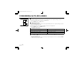
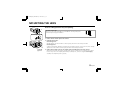
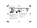
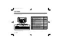
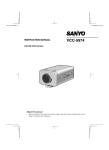
L53H4/US (VCC-6594) GB 2001, 11, 9
INSTRUCTION MANUAL
COLOR CCD CAMERA
About this manual
Before installing and using the camera, please read this manual
carefully. Be sure to keep it handy for later reference.
VCC-6594
L53H4/US (VCC-6594) GB 2001, 11, 9
SANYO INDUSTRIAL VIDEO
COLOR VIDEO CAMERA LIMITED WARRANTY
OBLIGATIONS
In order to obtain warranty service, the product must be delivered to and picked up from an Authorized Sanyo Service Center at the user’s expense, unless specifically stated otherwise in this warranty. The names and
addresses of Authorized Sanyo Service Centers may be obtained by calling the toll-free number listed below.
For product operation, authorized service center referral, service assistance or problem resolution, call
CUSTOMER INFORMATION 1-800-421-5013
Weekdays 8:30 AM – 5:00 PM Pacific Time
For accessories and/or parts, call
PARTS ORDER INFORMATION 1-800-726-9662
Weekdays 8:30 AM – 5:00 PM Pacific Time
THIS WARRANTY IS VALID ONLY ON SANYO PRODUCTS PURCHASED OR RENTED IN THE UNITED STATES OF AMERICA, EXCLUDING ALL U.S. TERRITORIES AND PROTECTORATES. THIS WARRANTY APPLIES
ONLY TO THE ORIGINAL RETAIL PURCHASER OR END-USER. THE ORIGINAL DATED BILL OF SALE, SALES SLIP OR RENTAL AGREEMENT MUST BE SUBMITTED TO THE AUTHORIZED SANYO SERVICE CENTER
AT THE TIME WARRANTY SERVICE IS REQUESTED.
Subject to the OBLIGATIONS above and EXCLUSIONS below, SANYO Fisher Company warrants this SANYO product against defects in materials and workmanship for the periods specified below. SFC will repair or
replace (at its option) the product and any of its parts which fail to conform to this warranty. The warranty period commences on the date the product was first purchased or rented at retail.
LABOR
3 YEARS
PARTS
3 YEARS
IMAGE DEVICE
3 YEARS
EXCLUSIONS
This warranty does not cover (A) the adjustment of customer-operated controls as explained in the appropriate model’s instruction manual, or (B) the repair of any product whose serial number has been altered, defaced
or removed.
This warranty shall not apply to the cabinet or cosmetic parts, batteries or routine maintenance.
This warranty does not apply to uncrating, setup, installation, removal of the product for repair or reinstallation of the product after repair.
This warranty does not apply to repairs or replacements necessitated by any cause beyond the control of SFC including, but not limited to, any malfunction, defect or failure caused by or resulting from unauthorized
service or parts, improper maintenance, operation contrary to furnished instructions, shipping or transit accidents, modification or repair by the user, abuse, misuse, neglect, accident, incorrect power line voltage, fire,
flood or other Acts of God, or normal wear and tear.
The foregoing is in lieu of all other expressed warranties and SFC does not assume or authorize any party to assume for it any other obligation or liability.
SFC DISCLAIMS ALL OTHER WARRANTIES EXPRESS OR IMPLIED, WITH REGARD TO THIS PRODUCT (INCLUDING THE WARRANTIES OF MERCHANTABILITY AND FITNESS). IN NO EVENT SHALL SFC BE LIABLE
FOR ANY SPECIAL, INCIDENTAL OR CONSEQUENTIAL DAMAGES ARISING FROM THE OWNERSHIP OR USE OF THIS PRODUCT OR FOR ANY DELAY IN THE PERFORMANCE OF ITS OBLIGATIONS UNDER THIS
WARRANTY DUE TO CAUSES BEYOND ITS CONTROL. SFC’S LIABILITY FOR ANY AND ALL LOSSES AND DAMAGES RESULTING FROM ANY CAUSE WHATSOEVER, ARISING OUT OF OR IN CONNECTION WITH
THE SALE, USE OR OWNERSHIP OF THIS PRODUCT INCLUDING WARRANTOR’S NEGLIGENCE, ALLEGED DAMAGED OR DEFECTIIVE GOODS, WHETHER SUCH DEFECTS ARE DISCOVERABLE OR LATENT,
SHALL IN NO EVENT EXCEED THE PURCHASE PRICE OF THE PRODUCT.
ATTENTION
For your protection in the event of theft or loss of this product, please fill in the information below for you own personal records.
Model No._____________________________________________________________________
Serial No. _____________________________________________________________________
(Located on back or bottom side of unit.)
Date of Purchase _______________________________________________________________
Purchase Price _________________________________________________________________
Where Purchased _________________________________________________________________________________________________________________________________________________
L53H4/US (VCC-6594) GB 2001, 11, 9
1AC6P1P2413-L53H4/US(1101KPS-CZ)
21605 Plummer Street,
Chatsworth, California 91311
Printed in Japan
L53H4/US (VCC-6594) GB 2001, 11, 9
Depending on the conditions of use, installation and environment,
please be sure to make the appropriate settings and adjustments. If you
need help with installation and/or settings, please consult your dealer.
CONTENTS
INFORMATION TO USER . . . . . . . . . . . . . . . . . . . . . . . . . . . . . . . . . . . 2
PRECAUTIONS . . . . . . . . . . . . . . . . . . . . . . . . . . . . . . . . . . . . . . . . . . . 3
PARTS NAMES . . . . . . . . . . . . . . . . . . . . . . . . . . . . . . . . . . . . . . . . . . . 4
CONCERNING AUTO-IRIS LENSES . . . . . . . . . . . . . . . . . . . . . . . . . . . . 7
MOUNTING THE LENS . . . . . . . . . . . . . . . . . . . . . . . . . . . . . . . . . . . . . 8
CONNECTIONS . . . . . . . . . . . . . . . . . . . . . . . . . . . . . . . . . . . . . . . . . . .10
SETTINGS . . . . . . . . . . . . . . . . . . . . . . . . . . . . . . . . . . . . . . . . . . . . . . .11
TROUBLESHOOTING . . . . . . . . . . . . . . . . . . . . . . . . . . . . . . . . . . . . . .16
SPECIFICATIONS . . . . . . . . . . . . . . . . . . . . . . . . . . . . . . . . . . . . . . . . .17
ACCESSORIES
1 Lens iris plug (4-pin)..................................................................1 pc.
1
English
1
FEATURES
• Built-in interline transfer method 1/3" CCD, approx. 410,000
picture elements
• Equipped with a DSP (Digital Signal Processor) function
• Horizontal resolution, more than 520 TV lines
• High sensitivity, minimum required illumination is 0.3 lux (F1.2,
AGC HI position)
• Two types of backlight compensation functions (multi-spot
photometry and center focus photometry)
• Low smear, anti-blooming, low lag, no burning and no geometric
distortion using the CCD solid state image device.
• 100% solid state components giving excellent immunity to shock
and vibration
• Not subject to interference from magnetic or electrostatic fields
• Power supply: 24 V AC operation
L53H4/US (VCC-6594) GB 2001, 11, 9
INFORMATION TO USER
Safety Guard
THIS SYMBOL INDICATES THAT THERE ARE
IMPORTANT OPERATING AND MAINTENANCE
INSTRUCTIONS IN THE LITERATURE
ACCOMPANYING THIS UNIT.
WARNING:
TO PREVENT THE RISK OF FIRE OR ELECTRIC SHOCK , DO NOT
EXPOSE THIS APPLIANCE TO RAIN OR MOISTURE.
For the customers in Canada
This Class B digital apparatus complies with Canadian ICES-003.
Pour la clientèle canadienne
Cet appareil numerique de la Classe B est conforme a la norme
NMB-003 du Canada.
This installation should be made by a qualified service person and
should conform to all local codes.
This equipment has been tested and found to comply with the limits
for a Class B digital device, pursuant to Part 15 of the FCC Rules.
These limits are designed to provide reasonable protection
against harmful interference in a residential installation. This
equipment generates, uses, and can radiate radio frequency
energy and, if not installed and used in accordance with the
instructions, may cause harmful interference to radio
communications.
However, there is no guarantee that interference will not occur in
a particular installation. If this equipment does cause harmful
interference to radio or television reception, which can be
determined by turning the equipment off and on, the user is
encouraged to try to correct the interference by one or more of
the following measures:
– Reorient or relocate the receiving antenna.
– Increase the separation between the equipment and receiver.
– Connect the equipment into an outlet on a circuit different
from that to which the receiver is connected.
– Consult the dealer or an experienced radio/TV technician for help.
This device complies with Part 15 of the FCC Rules. Operation is
subject to the following two conditions: (1) This device may not
cause harmful interference, and (2) this device must accept any
interference received, including interference that may cause
undesired operation.
Changes or modifications not expressly approved by Sanyo may
void the user’s authority to operate this camera.
2 English
L53H4/US (VCC-6594) GB 2001, 11, 9
PRECAUTIONS
In case of problem
Do not use the camera if smoke or a strange odour comes from the
unit, or if it seems not to function correctly. Disconnect the power
cord immediately, and consult your dealer (or a Sanyo Authorized
Service Centre).
Do not open or modify
Do not open the cabinet, as it may be dangerous and cause damage
to the unit. For internal settings and repairs, consult your dealer (or a
Sanyo Authorized Service Centre).
Do not put objects inside the unit
Make sure that no metal objects or flammable substance get inside
the camera. If used with a foreign object inside, it could cause a fire,
short-circuits or damages.
If water or a liquid gets inside the camera, disconnect the power cord
immediately, and consult your dealer (or a Sanyo Authorized Service
Centre). Be careful to protect the camera from rain, sea water, etc.
Be careful when handling the unit
To prevent damages, do not drop the camera or subject it to strong
shock or vibration.
Install away from electric or magnetic fields
If installed close to a TV, radio transmitter, magnet, electric motor,
transformer, audio speakers the magnetic field they generate will
distort the image.
English
3
Protect from humidity and dust
To prevent damages to the camera, do not install it where there is
greasy smoke or steam, where the dampness may get too high, or
where there is a lot of dust.
Protect from high temperatures
Do not install close to stoves, or other heat generating devices, such
as spotlights, etc., or where it could be subject to direct sunlight, as
that could cause deformation, discoloration or other damages.
Be careful when installing close to the ceiling, in a kitchen or boiler
room, as the temperature may raise to high levels.
Install where the temperature range will stay between –10˚C and
50˚C.
(no condensation)
Cleaning
• Dirt can be removed from the cabinet by wiping it with a soft
cloth. To remove stains, wipe with a soft cloth moistened with a
soft detergent solution and wrung dry, then wipe dry with dry soft
cloth.
• Do not use benzine, thinner or other chemical product on the
cabinet, as that may cause deformation and paint peeling. Before
using a chemical cloth, make sure to read all accompanying
instructions. Make sure that no plastic or rubber material comes in
contact with the cabinet for a long period of time, as that may
cause damage or paint peeling.
L53H4/US (VCC-6594) GB 2001, 11, 9
PARTS NAMES
1 Video output connector (VIDEO OUT: BNC type)
Connect this connector to a device such as a VCR or monitor with a VIDEO IN connector.
1
4
3
2
2 Line phase adjustment volume (LINE PHASE)
When using two cameras or more, the image on the monitor may roll vertically when switching sources. This
rolling can be minimized by turning this volume.
3 Power input terminal
24 V AC input terminal (AC 24 V, GND)
4 Power indicator (POWER)
Comes on when the power to the camera is on.
4 English
L53H4/US (VCC-6594) GB 2001, 11, 9
PARTS NAMES
5 Lens mount cap
The cap is installed to protect the lens mount section.
Remove the lens mount cap before installing a lens (sold separately).
6 Flange-back adjustment screw (FLANGE BACK ADJ.)
7
5
6
8
7 Flange-back lock screw (FLANGE BACK LOCK)
8 Camera installation bracket
1
2
3 2
The bracket can be fixed at the top or bottom of the camera. When fixing the bracket, be sure to use the
longer screws and install the shorter screws on the opposite side to seal the openings.
CAUTION:
When installing the camera support, select a location that can support the total weight of the
camera and accessories.
1
1 Shorter screws: M3 x 4
2 Longer screws: M3 x 6
3 Camera mounting screw
hole: 1/4"-20 UNC
English
5
L53H4/US (VCC-6594) GB 2001, 11, 9
PARTS NAMES
9 Lens iris output connector (LENS)
This 4-pin connector is used to send the DC control signal and power supply to an auto-iris type lens.
F
F Camera setup section (under the cover)
9
These settings are for when using a 1/3 inch CS mount DC (without EE internal amplifier) type lens. However,
if due to installation conditions or environment the settings may need to be modified for best results (see
"SETTINGS"). To access the controls, remove the cover fixing screw, then remove the cover.
NOTE: When using a 1/2 or 2/3 inch C mount VIDEO (with EE internal amplifier) auto-iris type lens, set the
A.I. LENS switch to the VIDEO position.
6 English
L53H4/US (VCC-6594) GB 2001, 11, 9
CONCERNING AUTO-IRIS LENSES
VR301
DC
VIDEO
A. I.
LENS
DC type auto-iris lens
A lens without amplifier circuit that operates only on a DC power source. In general, this type of lens is
referred to as DC type coil lens or DC type non-amplifier lens.
(Set the A.I. LENS switch to the DC position.)
VIDEO type auto-iris lens
A lens with amplifier circuit that operates on video signal and DC power source. In general, this type of lens is
referred to as EE amplifier type lens.
ALC and LEVEL volume level controls are available on the lens for iris adjustments.
(Set the A.I. LENS switch to the VIDEO position.)
Compatible auto-iris lenses
1/3 inch Sanyo DC type lens
VCL-CS8LY: Standard angle, f= 8 mm
VCL-CS4LY: Wide angle, f= 4 mm
VCL-CS2LY: Ultra-wide angle, f= 2.8 mm
VIDEO type lens
Standard angle, f= 9 mm
Telephoto angle, f= 12 mm
Greater telephoto angle, f= 16 mm
If using a VIDEO type auto-iris lens
• Set the ALC and LEVEL controls on the lens to adjust the iris. Normally the ALC volume should be turned
all the way to Av (Average).
• Depending on the type of lens used, the lens may not perform properly. In such a case, adjust the LEVEL
volume on the lens casing to correct.
English
7
L53H4/US (VCC-6594) GB 2001, 11, 9
MOUNTING THE LENS
Please use a DC type auto-iris lens (sold separately).
1
C mount type lens
Check the lens mount
Do not use a lens if the length “L” is more than 5 mm. That may damage the
camera and prevent proper installation.
2
L
1
2
3
2
CS mount
type lens
3
Remove the lens mount cap from the camera.
Install the auto-iris lens.
CS mount type lens
Carefully align the lens mount with the camera opening, then turn the lens slowly to install it.
C mount type lens
To allow for flange-back adjustment, install the C-mount adaptor (option) on the lens mount, then carefully
align the lens mount with the camera opening and turn the lens slowly to install it.
Connect the lens plug to the lens iris output connector (LENS) on the side of the camera.
When using lenses from other makers, the plug shape may not correspond to the terminal on the camera.
In such a case, remove the original plug and using a soldering iron, connect the supplied lens iris plug
according to the diagram. (Refer to page 9.)
8 English
L53H4/US (VCC-6594) GB 2001, 11, 9
MOUNTING THE LENS
Rewiring the lens cable in the lens iris plug
1
1
2
2
Prepare the lens cable.
Cut the cable at the plug, then remove approx. 8 mm of the cable sheath and strip about 2 mm from each wire.
Install the lens iris plug.
Solder the cable to the pins following the correct pin layout (refer to the table and illustrations), then close
the plug cover.
Pin layout
2
1
3
4
2
1
4
3
1
2
3
4
DC type lenses
Brake coil (–)
Brake coil (+)
Drive coil (+)
Drive coil (–)
VIDEO type lenses
+12 V DC (50 mA max.)
Not used
Video output (1.0 Vp-p, high impedance)
Ground (for video signal and DC power)
Flange-back adjustment
If the pick-up surface is not correctly positioned with relation to the lens focal point, the picture will be out of
focus (in particular when using auto-iris power zoom lenses, sold separately). If that is the case, adjust the
flange-back position as described below.
2, 3
3
ADJ.
1
LOCK
4
English
9
1
2
3
4
Using a + screwdriver, loosen the FLANGE BACK LOCK screw (M2:+).
Set the zoom lens to the maximum telephoto position, set the focus using the focus ring on the lens.
Set the zoom lens to the maximum wide angle position, set the focus using the FLANGE BACK ADJ. screw.
Repeat steps 2 and 3, until the image stays in focus when changing from a telephoto shot to a wide angle shot.
When the setting is complete, tighten the FLANGE BACK LOCK screw.
L53H4/US (VCC-6594) GB 2001, 11, 9
CONNECTIONS
1
(A)
3
AC 24 V connection
Push to insert the cable
AC 24 V
2
(Video signal connections)
: VIDEO IN
: VIDEO OUT
~ ~
GND
Basic connection for monitoring or recording
The peripheral devices (VCR, monitor, lens, etc.), AC adaptor
and cables are sold separately.
1
Make the video signal connection between the camera and
the monitor or time lapse VCR.
2
Use a commercially available 24 V AC adaptor.
Connect an AC 24 V power source to the AC 24 V input terminal
on the back of the camera.
Insert the plug of this power cord into a wall outlet.
The POWER indicator (A) will light. Adjust the picture on the
monitor using the Brightness and Contrast controls etc.
3
Coaxial cable type and maximum length
• Cable type RG-59U (3C-2V), 250 m maximum.
• Cable type RG-6U (5C-2V), 500 m maximum.
• Cable type RG-11U (7C-2V), 600 m maximum.
CAUTION:
• The RG-59U type cable should not be run through electrical
conduits or through the air.
• Using CCTV/Video-grade coaxial cable.
10 English
L53H4/US (VCC-6594) GB 2001, 11, 9
SETTINGS
The illustration shows the factory default settings for the switches in the camera setup section.
The camera settings are described on the assumption that a DC type auto iris lens is being used. If you are using a VIDEO type auto iris lens, be
sure to read the Note which is given.
6
9
Control name
1 High speed electronic shutter (ES)/
R
B
VR302
Electronic iris (EI) setting
VR301
VR303
ON
1
2
3
4
5
6
7
8
DC
VIDEO
9 10
Position
1/60 sec.
A. I.
LENS
2 Auto gain control setting (HI/NORM)
NORM
3 Aperture compensation setting
(SHRP/NORM)
NORM
4 Backlight compensation setting (BLC)
OFF
(MULT/OFF)
1 2345678
5 Backlight compensation setting (BLC)
OFF
(CENT/OFF)
6 White balance switch (MANU/ATW) and
ES/EI
1
2
GAIN APER
3
HI
SHRP
BLC
WB
MULT CENT MANU
SYNC
LL
NC
7 Syncronisation (SYNC) setting (INT/LL)
INT
8 Auto-iris lens setting (A.I. LENS), see page 6
DC
9 Lens iris level adjustment volume
MSB
LSB
NORM NORM
OFF
* The sticker on the inside of cover.
English
11
OFF
ATW
INT
ATW
colour (R or B) adjustment volume
adjustable
L53H4/US (VCC-6594) GB 2001, 11, 9
SETTINGS
Electronic shutter settings and electronic iris
settings
When all of these switches are down, electronic shutter (1/60 sec or
auto iris setting) is enabled. The electronic shutter can be set to one
of 7 speeds as shown in Table A.
Furthermore, when all switches are up, electronic iris setting is
enabled.
Notes on the electronic shutter:
• Using the high speed electronic shutter indoors with low lighting,
•
•
•
•
will give darker pictures. In such a case, add some lights to make
sure the lighting is sufficient. If the lighting is very bright, pay
attention to the light angle in order to avoid or minimize the
smear phenomenon effect.
Use a manual or fixed iris lens and set the lens aperture to the
shortest F stop. Set the switch (1 – 3) to the up position.
The electronic iris is suitable for normal indoor use. When the
switch (1 – 3) is set to the up position, do not use an auto-iris lens.
If used under fluorescent light, the image may flicker. In such a
case, change to incandescent lighting or set the switch (1 – 3) to
the down position and use an auto-iris lens.
If conditions are outside the electronic iris operation range or
more than the maximum illumination, it will cause saturation of
the CCD. In that case, use a manual iris lens.
Table A (switch 1 ~ 3)
1
2
3
4
5
6
7
8
1/60(AI) 1/100 1/500 1/1000 1/2000 1/4000 1/10000 EI
1
2
3
1
2
3
1
2
3
1
2
3
1
2
3
1
2
3
1
2
3
1
2
3
(Unit: sec.)
Automatic Gain Control (AGC) setting
The automatic gain control can be turned HI or NORM
using the AGC switch 4 in the camera setup section.
HI: Auto gain control fuction on (+6 dB)
NORM: Auto gain control (normal gain)
4
Note: In the AGC switch position HI, noise may be noticed in dark
places of dimly lit objects. In the AGC switch position NORM,
the noise will be reduced, but the sensitivity will also be
reduced to half in this case.
Aperture
This switch 5 (APER) is normally set to the down
(NORM) position. If you would like to emphasize the
contours of the object, set the switch 5 (APER) to the
up (SHRP) position.
5
12 English
L53H4/US (VCC-6594) GB 2001, 11, 9
SETTINGS
Backlight compensation setting
This camera has two different backlight
compensation functions: Normally backlight
compensation switch 6 (MULT) and 7 (CENT)
are set to the down (OFF) position. Change
6
7
the backlight compensation switch settings
depending on the conditions.
• MULT mode: Use this position when applying backlight
compensation to the whole of the screen.
• CENT mode: Use this position when applying backlight
compensation to only the central portion of the
screen.
Note:
• If switches 6 and 7 are set to the up (ON) position at the same
time, the MULT setting will have priority.
• When MULT mode is set, scenes with no backlighting may appear
extremely dark and the object may appear over-exposed. If this
happens, set to CENT mode.
English
13
(MULTI mode: 64 sections)
(CENT mode)
If using a VIDEO type auto-iris lens
• The ALC volume on the lens should be turned all the way to Av
(Average).
• If the backlight compensation function does not compensate
properly for the conditions, set using the LEVEL volume on the
lens.
L53H4/US (VCC-6594) GB 2001, 11, 9
SETTINGS
White balance adjustment
Normally the switch 8 (WB) is set to the down (ATW: auto white
balance) position and the white balance is adjusted automatically. If a
manual white balance adjustment is necessary, follow the steps below.
Set the switch 8 (WB) to the up (M: manual) position, then adjust the
colour.
• Turn RED (VR302) to set the red ratio and/or BLUE (VR303) to set
the blue ratio.
R
8
B
VR302
VR303
Lens iris adjustment
If using a DC type auto-iris lens, you will need to set the LEVEL
(VR301) volume when shooting in the conditions described below.
VR301
L (counterclockwise): To decrease the contrast
H (clockwise): To increase the contrast
• If shooting simultaneously in a dark room and through a bright
window.
• If the subject background is extremely bright or dark.
• If the brightness of the picture on the monitor is not correct.
14 English
L53H4/US (VCC-6594) GB 2001, 11, 9
SETTINGS
Line phase adjustment
When using a camera switcher to connect 2 cameras or more to one
monitor, there may be a vertical roll of the images when switched. In
such a case, set as described below.
1
2
Set the switch 9 (SYNC) to the up (LL) position.
Switch the display on the monitor from camera 1 to camera 2.
Adjust the LINE PHASE volume on camera 2 until the vertical roll
of the image stops.
If more than two cameras are used, please repeat this procedure
for all the cameras.
9
CAUTION:
If the vertical roll cannot be corrected by setting the LINE PHASE
volume on camera 2, try setting the LINE PHASE volume on camera
1. If it still cannot be corrected, please check that the polarity of the
power cords of all connected devices is correct.
English
15
L53H4/US (VCC-6594) GB 2001, 11, 9
TROUBLESHOOTING
Before taking the camera for repairs, please check below to make sure that the camera is used correctly. If it still does not perform correctly, please
consult your dealer or a Sanyo Authorized Service Centre.
No picture on the monitor screen
Is the power turned on to all connected devices? Is the voltage correct?
Are all the signal connecting cables correctly connected?
Is the lighting sufficient?
Has the lens cap been removed?
Is the lens type (DC or VIDEO) correctly selected?
Depending on the type of lens, the A. I. LENS switch must be set accordingly.
• Is the iris control correctly set?
•
•
•
•
•
•
•
•
•
The picture is not clear
Is the monitor correctly adjusted?
Is the flange-back position correctly set?
Is the lens focus correctly adjusted?
Are the lens surfaces clean?
If there is dust or finger prints on the lens, the image quality will deteriorate. To clean the lens use a soft cloth or a commercially available lens
cleaning set.
SERVICE
This camera is a precision instruments and if treated with care, will provide years of satisfactory performance. However, in the event of a problem,
the owner is advised not to attempt to make repairs or open the cabinet. Servicing should always be referred to your dealer or Sanyo Authorized
Service Centre.
16 English
L53H4/US (VCC-6594) GB 2001, 11, 9
SPECIFICATIONS
Camera:
Scanning system
Interlace
Image device
Picture elements
Effective picture
elements
Synchronizing system
Resolution
Video output level
Video S/N ratio
Minimum required
illumination
(incandescent
lighting)
Backlight
compensation
Iris function
Electronic iris range
Electronic shutter
Flange-back
White balance
Lens mount
AGC
Environmental
conditions
English
17
: NTSC standard TV system
(525 TV lines, 30 frames/sec.)
: PLL 2:1 interlace
: 1/3 inch solid state image device CCD
: 811 (H) x 508 (V)
: 768 (H) x 494 (V)
:
:
:
:
:
Internal sync, Line lock manually switchable
520 TV lines horizontally, 350 TV lines vertically
1.0 Vp-p/75 ohms, composite
More than 48 dB
Approx. 0.3 lux with a F 1.2 lens (AGC, HI)
Approx. 0.6 lux with a F 1.2 lens (AGC,
NORM)
: Manual MULT/CENT/OFF switching (Active
when using an auto-iris lens)
: AI/EI selectable by switches (Electronic shutter)
: 0.6 lux to 50,000 lux (F 1.2 lens)
: 7 speeds, selectable by switches:
(1/60, 1/100, 1/500, 1/1000, 1/2000,
1/4000, 1/10000 sec.)
: 12.5 mm ± 0.5 mm
: ATW/Manual switching
: CS mount
: HI/NORM
: Temperature: –10˚C ~ +50˚C
Humidity: less than 90% (no condensation)
Power supply
Power consumption
Weight
: 24 V AC, 60 Hz
: Approx. 2.8 W (with auto iris lens)
Approx. 2.1 W (without auto iris lens)
: Approx. 310 g (without lens)
Dimensions
56
109
100
0.5
45
11
12.6
22.4
1/4”–20 UNC
28
Features and specifications are subject to change without prior
notice or obligations.