1
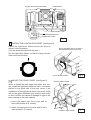
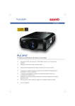
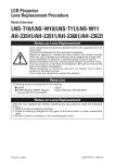
LCD PROJECTOR LENS
MODEL NO. LNS-S02Z
LENS REPLACEMENT
AND INSTALLATION PROCEDURES
NOTES ON REPLACEMENT AND INSTALLATION
The procedures and the needed pars for lens installation depend on the type of
cabinet. Before installing or replacing the lens, make sure the type of cabinet and be
sure to refer to the Installation Manual corresponding with your projector.
When installing or replacing the lens, make sure the Lens Model No. matches with
your projector. Refer to the catalog, or contact your sales dealer for the proper Lens
Model No.
TYPE OF THE CABINET AND REFERENCE INSTALLATION MANUAL
Refer to the Installation Manual corresponding to your projector.
(See the chart below.)
Type of the Cabinet
Reference Installation Manual
Refer to this manual.
Other than the above cabinet
design.
Refer to the Installation Manual
supplied with the Projector.
NOTES ON LENS INSTALLATION
• Lens installation and replacement should be made by the qualified service personnel.
• Be sure to install the lens following this procedure precisely.
• The lens cover is on the lens for protection. Be sure to replace the lens cover before
installation.
• When installing or replacing the lens, be careful not to stain, scratch or damage the lens.
LIST OF CONTENTS
Following parts are included in the packing.
• LENS
1 pc.
• LENS MOUNTING SCREWS
2 pcs. (for spare)
• DRIVER
1 pc.
• LIGHT-BLOCK SHEET
1 pc.
BE SURE TO CHECK FOR SAFETY
After installing or replacing the lens, be sure to check the following for safety.
1. Check the lens is securely fixed by 4 screws.
2. Check no wiring is tangled on the gear of lens motor or the other mechanical
parts.
3. Check no part is missing, or no mounting part is loose.
Some parts are not used for installation or replacement. Keep these parts for later use.
Note : Figures in this manual may be differ from the actual product.
LENS REPLACEMENT AND INSTALLATION PROCEDURE
Perform the steps 1 to 5 for lens replacement and installation.
C
UPPER LENS COVER
1
REMOVE THE LENS COVER. (See figure-1)
1. Remove screws A (2 screws).
2. Pull down the lower lens cover while pushing
the part D, then remove it.
3. Remove screws B (2 screws).
B
4. Remove screws C (2 screws) and remove
upper lens cover.
D
D
A
2
Fig-1
LOWER LENS COVER
REMOVE THE COVER PLATE OF THE LENS COVER. (See figure-2)
Remove 2 screws and pull down the plate.
(At the step 4 , insert the light-block sheet in
the same position as the removed cover plate
has been placed. Two screws are not used.)
COVER PLATE
3
Fig-2
INSTALL THE LENS. (See figure-3)
1. Remove protective caps(front and back) on the
lens.
2. Mount the lens on mounting bracket of the main
cabinet with 4 screws.Use the screws included
with the lens.
Use the driver included with the lens to fasten the
screws. (After using, save it for latter use.)
LENS MOUNTING BRACKET
3. Connect the lead connector of the lens motor to
the “K16B” on the circuit board as
shown in figure-4.
4. Fasten the lens motor lead at the
A, B points with wire holder as
shown in figure-4.
ATTACHED DRIVER
LENS MOTOR
Fig-3
❋ Figure shown inside of the cabinet.
(D)
LENS MOTOR
(D)
(D)
(D)
B
A WIRE HOLDER
LENS MOTOR LEAD
CONNECTOR “ K16B”
Fig-4
4
INSTALL THE LIGHT-BLOCK SHEET. (See figure-5)
Install the light-block sheet around the lens as
shown in the illustration.
(Use the sheet included with the lens.)
Set the light-block sheet, so that the
large rounder side is set over the lens.
Set the light-block sheet, so that the large rounder
side is set over the lens.
Fig-5
LIGHT-BLOCK SHEET
5
MOUNT THE LENS COVER. (See figure-6)
UPPER LENS COVER
A
When in install the both upper and lower lens covers, install the light-block sheet so that it should be
placed in the guide slot of the lens cover. If the
installation of the light-block sheet is incorrect, there
will be the space between lens and the lens cover,
so that it will be the cause of leakage of light or the
dust entering at the main cabinet.
1. Insert the upper part lens cover and fix
them with screws A (4 screws).
2. Insert the lower part lens cover and fix them
with screws B. (2 screws).
A
B
LOWER LENS COVER
Fig-6