1
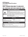
LCD Projector
Lens Replacement Procedure
Model Number
LNS-T10/LNS-W10/LNS-T11/LNS-W11
AH-23541/AH-23511/AH-23661/AH-23631
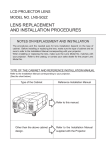
Notes on Lens Replacement
Lens replacement should be performed by the qualified service
personnel.
It should be followed by this procedure precisely.
Before an attempt to replace the lens, confirm the model number
(both the LCD projector and the lens) and prepare the proper lens.
Lens installation is different in cabinet design (Type A and B).
Before installation the lens, check cabinet design should be made.
The lens cover is on the lens for protection. Be sure to remove the
lens cover before installation.
When installing or removing the lens, be careful not to stain,
scratch or damage the lens.
If you have any questions, contact the dealers.
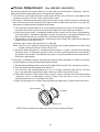
Parts List
Following parts are contained in the packing.
1 piece
● LENS
1 piece (Part No. 910 322 9677)
● LIGHT-BLOCK SHEET (Spare)
{Except LNS-W11 (AH-23631)}
Notes on Lens Replacement
After the lens replacement (before attaching the top cabinet), check the following
things.
1. Check the lens is properly installed.
2. Check no wiring is tangled on the gear of the lens motor or other mechanical
parts.
3. Check no parts is missing, or no mounting part is lost.
Printed in Japan
1AA6P1P5412-- (IFEK-EI)
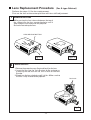
Lens Replacement Procedure
(For A type Cabinet)
Perform the steps 1-2 for lens replacement.
First set the lens at the center position with lens shift adjustment.
1
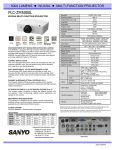
Remove the Lens
While pressing the Lens release button on the top of
the cabinet, turn the lens counterclockwise until it
stops and pull it out slowly from the projector.
Be careful not to drop the lens.
LENS RELEASE BUTTON
Fig-1-1
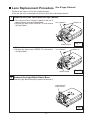
2
Fig-1-2
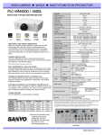
Mount the Lens
1. Remove the protective caps (front and back) on the lens.
2. Insert the lens into the Lens Bracket of the projector as
matching the red mark on the lens to that on the Lens
Bracket.
3. Slowly turn the lens clockwise until it clicks. Make sure that
the lens is fully inserted to the projector.
Red mark
Fig-2
-2-
Lens Replacement Procedure
(For B type Cabinet)
Perform the steps 1-6 for lens replacement.
First set the lens at the lowest position with lens shift adjustment.
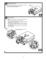
1
Remove the Lens Cover and the Top Cabinet
1. Turn the Lens Cover counter-clockwise and pull it
toward front to remove the Lens Cover.
2. Remove the two screws (SCREW "A") and remove
the Top Cabinet.
TOP CABINET
LENS COVER
1. Pull Lens Cover toward front and remove it.
2. Remove the two screws (SCREW "A") and remove
the Top Cabinet.
TOP CABINET
LENS COVER
2
SCREW "A"
Fig-1-1
SCREW "A"
Fig-1-2
Remove the Light-Block Sheet Base
Slide the Light-Block Sheet Base upward to remove it.
LIGHT-BLOCK
SHEET BASE
Fig-2
-3-
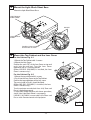
3
Remove the Lens
Push the Lens Lock Lever and turn the lens counterclockwise (1/4 turn) and then take it out.
Be careful not to drop the lens.
LENS LOCK
LEVER
Fig-3
4
Mount the Lens
1. Remove the protective caps (front and back) on the
lens.
2. Put the Light-Block Sheet through the lens.
{When LNS-W11 (AH-23631) is installed, the Light
Block Sheet is unnecessary.}
3. Insert the lens into the Lens Bracket of the projector
as matching the red mark on the lens to that on the
Lens Bracket.
4. Turn the lens clockwise until the lens is locked with
Lens Lock Lever.
LENS
BRACKET
Insert the lens into the Lens Bracket
as matching these marks.
Fig-4
-4-
5
Mount the Light-Block Sheet Base
Mount the Light-Block Sheet Base.
LIGHT-BLOCK
SHEET BASE
HOOKS
LIGHT-BLOCK
SHEET
Light-Block Sheet should be
located under the hooks.
Fig-5
HOOKS
6
Mount the Top Cabinet and the Lens Cover
For the Cabinet Fig. 6-1
1. Mount the Top Cabinet with 2 screws.
2. Mount the Lens Cover.
Position the mark "UP" of the Lens Cover on top and
push into the cabinet. Turn the Lens Cover
clockwise until it is securely locked.
{When LNS-W11 (AH-23631) is installed, the Lens
Cover is unnecessary.}
For the Cabinet Fig. 6-2
1. Mount the top cabinet with 2 screws.
2. Push into the Lens Cover to the Top Cabinet.
Confirm the top and bottom of the lens cover.
The part circled in Fig-6-2 should be fitted.
{When LNS-W11 (AH-23631) is installed, the Lens
Cover is unnecessary.}
UP
Fig-6-1
Turn the projector on and check Lens shift, Zoom and
Focus is operating properly.
If Light-Block Sheet interfere with those operations,
check if the Light-Block Sheet is set properly.
LNS-W11 (AH-23631) cannot adjust the Zoom and
Focus at the Remote control or the projector.
Fig-6-2
-5-
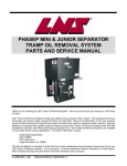
Focus Adjustment
{For LNS-W11 (AH-23631)}
Set up the projector in the place where it is to be used, turn on the power and project a picture.
Adjust the position of the projector to suit the projection position.
1. Turn the focus ring to adjust the focus at the center of the screen. The focus at the edges of the
screen may not be as sharp as at the center of the screen.
2. If the focus cannot be set correctly at the center of the screen, it will be necessary to move the
lens unit forward or back relative to the flange in order to adjust the back focus. Carry out this
adjustment according to the procedure given below.
a. Turn the fixing roulette about 1/4 of a turn counterclockwise to release it. The roulette can be
released more easily if you place the tip of your finger on the pin where the roulette is.
b. If the current focal point is somewhere forward of the screen, turn the focus ring clockwise;
if the focal point is somewhere behind the screen, turn the focus ring counterclockwise, and
then turn the precision lens unit (the focus ring and the fixing roulette) 5 degrees.
c. Turn the focus ring to adjust the focus at the center of the screen. (Be careful not to move the
whole of the lens unit at this time.)
d. Repeat steps b and c until correct focus is obtained.
Note: If the lens unit is difficult to move when carrying out the above procedure, turn the fixing
roulette counterclockwise a further 1/4 of a turn.
e. Once the above adjustment is complete and the picture is in focus, turn the fixing roulette
clockwise until it is tightened securely. Do this carefully, otherwise the focus may become
disrupted. If the roulette is not tightened securely, it may become difficult to remove the lens
during lens replacement.
3. If the focus cannot be correctly adjusted even after the above procedure has been carried out,
try adjusting by carrying out the procedure given below.
a. Set the distance between the screen and the edge of the lens to 0.77 m and project a picture.
b. Turn the roulette counterclockwise to release it.
c. Turn the focus ring counterclockwise as far as it will go, and then move the lens unit (the
focus ring and the fixing roulette) to adjust the focus at the center of the screen.
d. Check that the focus at the center of the screen is correct, and then turn the fixing roulette
clockwise until it is tightened securely. Check that the focus ring is still turned
counterclockwise as far as it will go at this time.
e. Return the projector to its original setup location and repeat steps 1 and 2 to adjust the focus.
PIN
FOCUS RING
FLANGE
ROULETTE
NOTE: Please remove 3 pins when you install it in the cabinet of B type.
-6-