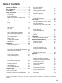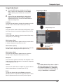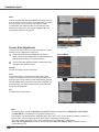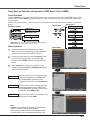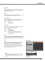
1
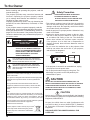
Multimedia Projector Network Supported MODEL PLC-WXU700 IEEE802.11b/g/n □ Wired LAN 100-Base-TX/10-Base-T □ Wireless LAN Memory Viewer □ USB Memory Viewer * Refer to the owner’s manuals below for details about network and memory viewer function. ■ Network Set-up and Operation ■ Memory viewer function Owner’s Manual Features and Design This Multimedia Projector is designed with the most advanced technology for portability, durability, and ease of use. This projector utilizes built-in multimedia features, a palette of 16.77 million colors, and matrix liquid crystal display (LCD) technology. ♦ Compact Design - You can project an image on a computer as well as operate and manage the projector via network. This projector is designed compact in size and weight. It is easy to carry and installed anywhere you wish to use. - This projector corresponds to "Connect to a Network Projector" function that is the standard equipment for Windows Vista. ♦ Capable of 360-degree Projection - The projector has the movie files transmission function that can play movie files transmitted from a computer to the projector. This function enables to playback movies very smoothly. This projector also corresponds to IEEE802.11n(Draft2.0). This projector is capable of 360-degree projection. *Some restriction required, see page 7. ♦ Simple Computer System Setting The projector has the Multi-scan system to conform to almost all computer output signals quickly (p.32). Up to WUXGA resolution can be accepted. ♦ Power Management The Power management function reduces power consumption and maintains the lamp life (p.56). ♦ Quick Termination The AC power cord can be unplugged immediately after turning off the projector without waiting for the termination of the cooling fan rotation (p.23). ♦ Logo Function The Logo function allows you to customize the screen logo (pp.50-52). You can capture an image for the screen logo and use it for the starting-up display or between presentations. - This projector is capable of the wireless LAN simple setting function by attaching the supplied USB memory to a computer. For details, refer to the owner’s manual of “Network Set-up and Operation.” ♦ Memory Viewer Function For details, refer to the owner’s manual of "Memory viewer function". ♦ Auto setup Function ♦ Multilanguage Menu Display Operation menu is available in 17 languages; English, German, French, Italian, Spanish, Portuguese, Dutch, Swedish, Finnish, Polish, Hungarian, Romanian, Russian, Chinese, Korean, Japanese and Thai (p.47). The Security function helps you to ensure security of the projector. With the Key lock function, you can lock the operation on the top control or the remote control (p.59). PIN code lock function prevents unauthorized use of the projector (pp.22, 59-60). This function enables Input search, Auto Keystone correction and Auto PC adjustment by simple pressing the AUTO SETUP button (pp. 26,48). ♦ Colorboard Function ♦ Security Function Insert the dedicated USB memory into the projector to project images or movie files stored within. You do not have to carry computers or other equipment for a presentation. t the time of simple projection on the colored wall, A you can get the close color image to the color image projected on a white screen by selecting the similar color to the wall color from the preset four colors. ♦ Closed Caption his is a printed version of the program sound or other T information displayed on the screen. You can turn on the feature and switch the channels (p.57). ♦ Helpful Maintenance Functions ♦ Picture in Picture Function Lamp and filter maintenance functions provide for better and proper maintenance of the projector. ♦ LAN Network Function his projector is capable of projecting two images T simultaneously by using either built-in P in P mode or P by P mode (p.55). This projector is loaded with the Wired and Wireless LAN network functions. Note: •The On-Screen Menu and figures in this manual may differ slightly from the product. •The contents of this manual are subject to change without notice. Table of Contents Features and Design . . . . . . . . . . . . . . . . . . . 2 Table of Contents . . . . . . . . . . . . . . . . . . . . . 3 To the Owner . . . . . . . . . . . . . . . . . . . . . . . . . 4 Safety Instructions . . . . . . . . . . . . . . . . . . . . 5 Air Circulation 6 Moving the Projector 6 Installing the Projector in Proper Position 7 Compliance . . . . . . . . . . . . . . . . . . . . . . . . . . 8 Part Names and Functions . . . . . . . . . . . . . . 9 Front Back Bottom Rear Terminal Top Control Remote Control Remote Control Battery Installation Remote Control Operating Range Remote Control Code Laser Pointer Function Pointer Function Wireless Mouse Operation Adjustable Feet 9 9 9 10 11 12 13 13 13 14 14 15 15 Installation . . . . . . . . . . . . . . . . . . . . . . . . . . 16 Positioning the Projector 16 Connecting to a Computer 17 Connecting to Video Equipment 18 Connecting to Component Video Equipment 19 Connecting the AC Power Cord 20 Basic Operation . . . . . . . . . . . . . . . . . . . . . . 21 Turning On the Projector Turning Off the Projector How to Operate the On-Screen Menu Menu Bar Zoom and Focus Adjustment Auto Setup Function Keystone Correction Sound Adjustment 21 23 24 25 26 26 26 27 Remote Control Operation 28 Computer Input . . . . . . . . . . . . . . . . . . . . . . 30 Input Source Selection (Computer 1:RGB/Component/RGB(Scart)) 30 Input Source Selection (Computer 2:RGB) Computer System Selection Auto PC adjustment Manual PC adjustment Image Mode Selection Image Adjustment Screen Size Adjustment 31 32 33 34 36 37 38 Video Input . . . . . . . . . . . . . . . . . . . . . . . . . . 40 Input Source Selection (Video, S-video) Input Source Selection (Component, RGB Scart 21-pin,HDMI) Video System Selection Image Mode Selection Image Adjustment Screen Size Adjustment 40 41 42 43 44 46 Setting . . . . . . . . . . . . . . . . . . . . . . . . . . . . . 47 Setting 47 Information . . . . . . . . . . . . . . . . . . . . . . . . . . 63 Input Source Information Display 63 Maintenance and Cleaning . . . . . . . . . . . . . 64 WARNING indicator 64 Cleaning the Filters 65 Resetting the Filter Counter 65 Attaching the Lens Cap 66 Cleaning the Projection Lens 66 Cleaning the Projector Cabinet 66 Lamp Replacement 67 Resetting the Lamp Counter 68 Appendix . . . . . . . . . . . . . . . . . . . . . . . . . . . 69 Troubleshooting 69 Menu Tree 73 Indicators and Projector Condition 75 Compatible Computer Specifications 76 List of Picture in Picture 78 Technical Specifications 79 Optional Parts 80 PJ Link Notice 81 Configurations of Terminals 82 PIN Code Number Memo 83 USB Thumb Drive Case 83 Dimensions 84 Trademarks Each name of corporations or products in this book is either a registered trademark or a trademark of its respective corporation. To the Owner Before installing and operating this projector, read this manual thoroughly. This projector provides many convenient features and functions. Operating the projector properly enables you to manage those features and maintains it in good condition for many years to come. Improper operation may result in not only shortening the product-life, but also malfunctions, fire hazard, or other accidents. If your projector seems to operate improperly, read this manual again, check operations and cable connections and try the solutions in the “Troubleshooting” section on pages 69-72 of this manual. If the problem still persists, contact the dealer where you purchased the projector or the service center. CAUTION RISK OF ELECTRIC SHOCK DO NOT OPEN CAUTION: TO REDUCE THE RISK OF ELECTRIC SHOCK, DO NOT REMOVE COVER (OR BACK). NO USER-SERVICEABLE PARTS INSIDE EXCEPT LAMP REPLACEMENT. REFER SERVICING TO QUALIFIED SERVICE PERSONNEL. Safety Precaution WARNING: ● THIS APPARATUS MUST BE EARTHED. ● TO REDUCE THE RISK OF FIRE OR ELECTRIC SHOCK, DO NOT EXPOSE THIS APPLIANCE TO RAIN OR MOISTURE. –This projector produces intense light from the projection lens. Do not stare directly into the lens, otherwise eye damage could result. Be especially careful that children do not stare directly into the beam. –Install the projector in a proper position. Otherwise it may result in fire hazard. –Allowing the proper amount of space on the top, sides, and rear of the projector cabinet is critical for proper air circulation and cooling of the unit. The dimension shown here indicate the minimum space required. If the projector is to be built into a compartment or similarly enclosed, these minimum distances must be maintained. –Do not cover the ventilation slot on the projector. Heat build-up can reduce the service life of your projector, and can also be dangerous. SIDE and TOP REAR 0.7’(20cm) THIS SYMBOL INDICATES THAT DANGEROUS VOLTAGE CONSTITUTING A RISK OF ELECTRIC SHOCK IS PRESENT WITHIN THIS UNIT. THIS SYMBOL INDICATES THAT THERE ARE IMPORTANT OPERATING AND MAINTENANCE INSTRUCTIONS IN THE OWNER'S MANUAL WITH THIS UNIT. The symbol mark and recycling systems described below apply to EU countries and do not apply to countries in other areas of the world. Your product is designed and manufactured with high quality materials and components which can be recycled and/or reused. The symbol mark means that electrical and electronic equipment, batteries and accumulators, at their end-oflife, should be disposed of separately from your household waste. Note: If a chemical symbol is printed beneath the symbol mark, this chemical symbol means that the battery or accumulator contains a heavy metal at a certain concentration. This will be indicated as follows: Hg: mercury, Cd: cadmium, Pb: lead In the European Union there are separate collection systems for used electrical and electronic equipment, batteries and accumulators. Please, dispose of them correctly at your local community waste collection/recycling centre. Please, help us to conserve the environment we live in! 1.5’(50cm) 3’(1m) 3’(1m) –If the projector is unused for an extended time, unplug 20cm the projector from the power outlet. –Do not project the same image for a long time. The afterimage may remain on the LCD panels by the characteristic of panel. 50cm 1m 1m CAUTION Do not set the projector in greasy, wet, or smoky conditions such as IN a kitchen to prevent A Breakdown or a disaster. If The PROJECTor comes in contact with oil or chemicals, IT may become deteriorated. CAUTION Not for use in a computer room as defined in the Standard for the Protection of Electronic Computer/Data Processing Equipment, ANSI/NFPA 75. Ne peut être utilisé dans une salle d’ordinateurs telle que définie dans la norme ANSI/NFPA 75 Standard for Protection of Electronic Computer/Data Processing Equipment. READ AND KEEP THIS OWNER'S MANUAL FOR LATER USE. Safety Instructions All the safety and operating instructions should be read before the product is operated. Do not install the projector near the ventilation duct of air-conditioning equipment. Read all of the instructions given here and retain them for later use. Unplug this projector from AC power supply before cleaning. Do not use liquid or aerosol cleaners. Use a damp cloth for cleaning. This projector should be operated only from the type of power source indicated on the marking label. If you are not sure of the type of power supplied, consult your authorized dealer or local power company. Follow all warnings and instructions marked on the projector. Do not overload wall outlets and extension cords as this can result in fire or electric shock. Do not allow anything to rest on the power cord. Do not locate this projector where the cord may be damaged by persons walking on it. For added protection to the projector during a lightning storm, or when it is left unattended and unused for long periods of time, unplug it from the wall outlet. This will prevent damage due to lightning and power line surges. Do not expose this unit to rain or use near water... for example, in a wet basement, near a swimming pool, etc... Do not use attachments not recommended by the manufacturer as they may cause hazards. Do not place this projector on an unstable cart, stand, or table. The projector may fall, causing serious injury to a child or adult, and serious damage to the projector. Use only with a cart or stand recommended by the manufacturer, or sold with the projector. Wall or shelf mounting should follow the manufacturer’s instructions, and should use a mounting kit approved by the manufacturers. An appliance and cart combination should be moved with care. Quick stops, excessive force, and uneven surfaces may cause the appliance and cart combination to overturn. Slots and openings in the back and bottom of the cabinet are provided for ventilation, to ensure reliable operation of the equipment and to protect it from overheating. Do not attempt to service this projector yourself as opening or removing Covers may expose you to dangerous voltage or other hazards. Refer all servicing to qualified service personnel. Unplug this projector from wall outlet and refer servicing to qualified service personnel under the following conditions: a.When the power cord or plug is damaged or frayed. b.If liquid has been spilled into the projector. c.If the projector has been exposed to rain or water. d.If the projector does not operate normally by following the operating instructions. Adjust only those controls that are covered by the operating instructions as improper adjustment of other controls may result in damage and will often require extensive work by a qualified technician to restore the projector to normal operation. e.If the projector has been dropped or the cabinet has been damaged. f. When the projector exhibits a distinct change in performance-this indicates a need for service. When replacement parts are required, be sure the service technician has used replacement parts specified by the manufacturer that have the same characteristics as the original part. Unauthorized substitutions may result in fire, electric shock, or injury to persons. The openings should never be covered with cloth or other materials, and the bottom opening should not be blocked by placing the projector on a bed, sofa, rug, or other similar surface. This projector should never be placed near or over a radiator or heat register. Upon completion of any service or repairs to this projector, ask the service technician to perform routine safety checks to determine that the projector is in safe operating condition. This projector should not be placed in a built-in installation such as a book case unless proper ventilation is provided. NOTE FOR CUSTOMERS IN THE US Hg LAMP(S) INSIDE THIS PRODUCT CONTAIN MERCURY AND MUST BE RECYCLED OR DISPOSED OF ACCORDING TO LOCAL, STATE OR FEDERAL LAWS. Never push objects of any kind into this projector through cabinet slots as they may touch dangerous voltage points or short out parts that could result in a fire or electric shock. Never spill liquid of any kind on the projector. Safety Instructions Air Circulation Moving the Projector Openings in the cabinet are provided for ventilation. To ensure reliable operation of the product and to protect it from overheating, these openings must not be blocked or covered. CAUTION Hot air is exhausted from the exhaust vent. When using or installing the projector, the following precautions should be taken. –Do not put any flammable object or spray can near the projector, hot air is exhausted from the air vents. –Keep the exhaust vent at least 3’ (1 m) away from any objects. – Do not touch a peripheral part of the exhaust vent, especially screws and metallic parts. These areas will become hot while the projector is being used. – Do not put anything on the cabinet. Objects put on the cabinet will not only get damaged but also may cause fire hazard by heat. Cooling fans are provided to cool down the projector. The fans’ running speed is changed according to the temperature inside the projector. Air Intake Vent Exhaust Vent (Hot air exhaust) Air Intake Vent Air Intake Vent When moving the projector, replace the Lens Cap and retract adjustable feet to prevent damage to the lens and cabinet. When the projector is not in use for an extended period, put it into the supplied carrying case with the lens side up. CAUTION The carrying case (supplied) is intended for protection against dust and scratches on surface of the cabinet, and it is not designed to protect an appliance from external forces. Do not transport the projector by courier or any other transport service with this case, otherwise the projector can be damaged. When handling the projector, do not drop, bump, subject it to strong forces, or put other things on the cabinet. CAUTION IN CARRYING OR TRANSPORTING THE PROJECTOR –Do not drop or bump the projector, otherwise damages or malfunctions may result. –When carrying the projector, use a suitable carrying case. –Do not transport the projector by courier or any other transport service in an unsuitable transport case. This may cause damage to the projector. For information about transporting the projector by courier or any other transport service, consult your dealer. –Do not put the projector in a case before the projector is cooled enough. Safety Instructions Installing the Projector in Proper Directions Use the projector properly in specified positions. Improper positioning may reduce the lamp life and result in severe accident or fire hazard. This projector can project the picture upward, downward or backward, perpendicular to the plane of the screen as shown in the figure below. Bottom Downward (Usual) Front Upward Bottom Upward Front Downward 90º 40º Be sure to set the Lamp control in High and the Fan control in On 3 in the setting menu when using the projector inclined at between +40 degrees to +140 degrees to the horizontal plane at altitudes between 0 and approximately 1,600 meters above sea level. 140º 50º 50º 180 º 40º 0º Be sure to set the Fan control in On 2 when using the projector at higher altitudes than the altitudes described above, regardless of the installation position of the projector. (p.61). Positioning Precautions Avoid positioning the projector as described below when installing. 10˚ Do not roll the projector more than 10 degrees from side to side. 10˚ Do not put the projector on either side to project an image. 10˚ 10˚ In upward projection, do not tilt the projector over 10 degrees right and left. In downward projection, do not tilt the projector over 10 degrees right and left. 10˚ 10˚ Compliance Federal Communications Commission Notice Note: This equipment has been tested and found to comply with the limits for a Class B digital device, pursuant to Part 15 of the FCC Rules. These limits are designed to provide reasonable protection against harmful interference in a residential installation. This equipment generates, uses, and can radiate radio frequency energy, and if not installed and used in accordance with the instructions, may cause harmful interference to radio communications. However, there is no guarantee that interference will not occur in a particular installation. If this equipment does cause harmful interference to radio or television reception, which can be determined by turning the equipment off and on, the user is encouraged to try to correct the interference by one or more of the following measures: –Reorient or relocate the receiving antenna. –Increase the separation between the equipment and receiver. –Connect the equipment into an outlet on a circuit different from that to which the receiver is connected. –Consult the dealer or an experienced radio/TV technician for help. Use of shielded cable is required to comply with class B limits in Subpart B of Part 15 of FCC Rules. Do not make any changes or modifications to the equipment unless otherwise specified in the instructions. If such changes or modifications should be made, you could be required to stop operation of the equipment. Model Number : PLC-WXU700 Trade Name : Sanyo Responsible party : SANYO FISHER COMPANY Address : 21605 Plummer Street, Chatsworth, California 91311 Telephone No. : (818)998-7322 AC Power Cord Requirement The AC Power Cord supplied with this projector meets the requirement for use in the country you purchased it. AC Power Cord for the United States and Canada: AC Power Cord used in the United States and Canada is listed by the Underwriters Laboratories (UL) and certified by the Canadian Standard Association (CSA). AC Power Cord has a grounding-type AC line plug. This is a safety feature to be sure that the plug will fit into the power outlet. Do not try to defeat this safety feature. Should you be unable to insert the plug into the outlet, contact your electrician. GROUND AC Power Cord for the United Kingdom: This cord is already fitted with a moulded plug incorporating a fuse, the value of which is indicated on the pin face of the plug. Should the fuse need to be replaced, an ASTA approved BS 1362 fuse must be used of the same rating, marked thus . If the fuse cover is detachable, never use the plug with the cover omitted. If a replacement fuse cover is required, ensure it is of the same colour as that visible on the pin face of the plug (i.e. red or orange). Fuse covers are available from the Parts Department indicated in your User Instructions. If the plug supplied is not suitable for your socket outlet, it should be cut off and destroyed. The end of the flexible cord should be suitably prepared and the correct plug fitted. WARNING : A PLUG WITH BARED FLEXIBLE CORD IS HAZARDOUS IF ENGAGED IN A LIVE SOCKET OUTLET. The Wires in this mains lead are coloured in accordance with the following code: Green-and-yellowEarth Blue . . . . . . . . . . Neutral Brown . . . . . . . . . Live As the colours of the wires in the mains lead of this apparatus may not correspond with the coloured markings identifying the terminals in your plug proceed as follows: The wire which is coloured green-and-yellow must be connected to the terminal in the plug which is marked by the letter E or by the safety earth symbol or coloured green or green-and-yellow. The wire which is coloured blue must be connected to the terminal which is marked with the letter N or coloured black. The wire which is coloured brown must be connected to the terminal which is marked with the letter L or coloured red. WARNING: THIS APPARATUS MUST BE EARTHED. ASA THE SOCKET-OUTLET SHOULD BE INSTALLED NEAR THE EQUIPMENT AND EASILY ACCESSIBLE. Part Names and Functions Front ① Infrared Remote Receiver ② WIRELESS Indicator ③ Focus Ring ④ Projection Lens ⑤ Zoom Lever ⑥ Lens Cap CAUTION ① ② ③ ④ ⑤ ⑧ ⑥⑦ ⑧ Back Do not turn on a projector with lens cap attached. High temperature from light beam may damage lens cap and result in fire hazard. ⑦ Top Controls and Indicators ⑧ Air Intake Vent ⑨ Exhaust vent ⑨ CAUTION Hot air is exhausted from the exhaust vents. Do not put heat-sensitive objects near this side. ⑩ Speaker ⑪ Air Intake Vent (back and bottom) ⑫ Terminals and Connectors ⑬ Power Cord Connector ⑭ USB Connector (Series A) ⑩ ⑪ ⑫ ⑬ ⑮ LAN Connection Terminal ⑯ Lamp Cover Bottom ⑯ ⑪ ⑭ ⑮ ⑰ Filters ⑰ ⑱ Adjustable Feet Note: ② WIRELESS Indicator and ⑮ LAN Connection Terminal are for the Network function. Refer to the owner’s manual of “Network Set-up and Operation”. ⑭ USB Connector (Series A) is for the Memory Viewer function. Refer to the owner's manual of "Memory Viewer function". Kensington Security Slot ⑱ This slot is for a Kensington lock used to deter theft of the projector. * Kensington is a registered trademark of ACCO Brands Corporation. Part Names and Functions Rear Terminal ① ② * ③ ④ ⑬ ⑫ ① R/C JACK When using the wired remote control, connect the wired remote control to this jack with a remote control cable (not supplied). ② USB Connector (Series B) In order to operate the computer with the remote control and use the PAGE ▲▼buttons on the remote control during a presentation, connect the USB port of the computer to the USB terminal with a USB cable (not supplied) (p.17). ③ CONTROL PORT When controlling the projector with RS-232C, connect the control equipment to this connector with the serial control cable. ④ COMPUTER IN 1 / COMPONENT IN Connect output signal from a computer, RGB scart 21-pin video output or component video output to this terminal (pp.17,19). ⑤ COMPUTER IN 2 / MONITOR OUT – Connect computer output to this terminal (p.17). – This terminal can be used to output the incoming analog RGB signal and component signals from COMPUTER IN 1/COMPONENT IN terminal to the other monitor (p.17). ⑥ HDMI Connect the HDMI signal (including sound signal) from video equipment or the DVI signal from computer to this terminal (pp.17, 19). ⑦ LAN Connection Terminal Connect the LAN cable (refer to the owner’s manual of “Network Set-up and Operation”). 10 ⑤ ⑪ ⑥ ⑩ ⑨ ⑦ ⑧ ⑧ USB Connector (Series A) Connect the USB menory (refer to the owner’s manual “Network Set-up and Operation”). ⑨ S-VIDEO IN Connect the S-VIDEO output signal from video equipment to this jack (p.18). ⑩ AUDIO OUT (VARIABLE) Connect an external audio amplifier to this jack (pp.17-19). This terminal outputs sound from AUDIO IN terminal (⑪ or ⑫). ⑪ COMPUTER 1 COMPONENT / COMPUTER 2 AUDIO IN Connect the audio output (stereo) from a computer or video equipment connected to ④, ⑤ or ⑥ to this jack. (pp17, 19) ⑫ AUDIO IN Connect the audio output signal from video equipment connected to ⑨ or ⑬ to this jack. For a mono audio signal (a single audio jack), connect it to the L (MONO) jack (p.18). ⑬ VIDEO IN Connect the composite video output signal to this jack (p.18). is registered trademarks of HDMI * Licensing, LLC. Part Names and Functions Top Control ⑩ ⑥ ⑨ ⑤ ⑧ ④ ⑦ ③ ② ① ① SELECT button –Execute the selected item (p.24). –Expand or compress the image in the Digital zoom mode (p.39). ② POINT ▲▼◄► (VOLUME +/–) buttons –Select an item or adjust the value in the On-Screen Menu (p.24). –Pan the image in the Digital zoom + mode (p.39). –Adjust the volume level (Point ◄► buttons) (p.27). ③ MENU button Open or close the On-Screen Menu (p.24). ④ AUTO SETUP/CANCEL button –Correct vertical keystone distortion and adjust computer display parameters such as Fine sync, Total dots, Horizontal and Vertical position (pp.26, 48). –Display the image in USB thumb drive or return to the menu bar in Memory Viewer menu. Refer to the owner's manual of "Memory Viewer function". ⑥ WARNING indicator –Lights red when the projector detects an abnormal condition. –Blinks red when the internal temperature of the projector exceeds the operating range (pp.64, 75). ⑦ KEYSTONE button Correct keystone distortion (pp.26, 49). ⑧ INPUT button Select an input source (pp.30-31, 40-41). ⑨ ON/STAND–BY button Turn the projector on or off (pp.21-23). ⑩ LAMP REPLACE indicator Lights yellow when the projection lamp reaches its end of life (pp.67, 75). ⑤ POWER indicator –Lights red when the projector is in stand-by mode. –Lights green during operations. –Blinks green in the Power management mode (p.56). 11 Part Names and Functions Remote Control ⑤ Laser Light window A laser beam is emitted from here (p.14). ⑥ HDMI button Select the HDMI input source. (pp.28,41) ⑦ COMPUTER button Select the COMPUTER input source. (pp.30-31, 41) ⑧ INFO. button Operate the information function. (p.63) ① ⑤ ④ ③ ② ⑥ ㉙ ⑦ ㉘ ⑧ ⑨ ㉗ ⑩ ㉖ ㉕ ⑪ ㉔ ⑫ ⑬ ㉓ ㉒ ⑭ ㉑ ⑮ ⑳ ⑯ ⑲ ⑱ ⑨KEYSTONE button Correct keystone distortion. (pp.26, 49) ⑩ Point ▲▼◄► ( VOLUME + / – ) buttons –Select an item or adjust the value in the On-Screen Menu. (p.24) –Pan the image in the Digital zoom + mode. (p.39) –Adjust the volume level. (Point◄►buttons) (p.27) ⑪ MENU button Open or close the On-Screen Menu. (p.24) ⑫ FREEZE button Freeze the picture on the screen. (p.28) ⑬ LASER button – Operate the Laser pointer function. Laser beam is emitted while pressing this button within 1 minute. When using this laser pointer for more than 1 minute, release the LASER button and press it again. (p.14) – Display the Pointer on the screen. (p.14) ⑭ PAGE ▲▼ buttons Scroll back and forth the pages on the screen when giving a presentation. To use these buttons, connect the projector and your computer with a USB cable. (pp.10, 17) ⑮ LAMP button Select a lamp mode. (pp.28, 58) ⑯ D.ZOOM +/- buttons Zoom in and out the images. (pp.28, 39) ⑰ RESET/ON/ALL-OFF switch When using the remote control, set this switch to “ON.” Set it to “ALL OFF” for power saving when it is not used. Slide this switch to “RESET” to initialize the remote control code or switch Spotlight and Pointer to the Laser pointer function. (pp.13-14) ⑱ PIP button Operate the Picture In Picture function. (pp.28,55) ⑲ SCREEN button Select a screen mode. (pp.29,38-39,46) ⑳ IMAGE button Select the image mode. (pp.29,36,43) ㉑MUTE button Mute the sound. (p.27) ㉒P-TIMER button ⑰ ① L-CLICK button Act as the left mouse button for wireless mouse operation. (p.15) ② ON/STAND-BY button Turn the projector on or off. (pp.21-23) ③ WIRED REMOTE jack Connect the remote control cable(not supplied) to this jack when using as a wired remote control. Wireless remote control does not work when the remote control cable is connected to the projector. ④ SIGNAL EMISSION indicator Lights red while the laser beam is being emitted from the laser light window or a signal is being sent from the remote control to the projector. Note: To ensure safe operation, please observe the following precautions: – Do not bend, drop, or expose the remote control to moisture or heat. – For cleaning, use a soft dry cloth. Do not apply benzene, thinner, spray, or any chemical material. 12 Operate the P-timer function. (p.29) ㉓ NO SHOW button Temporarily turn off the image on the screen. (p.29) ㉔ R-CLICK button Act as the right mouse button for wireless mouse operation. (p.15) ㉕ SELECT button – Execute the selected item. (p.24) – Expand or compress the image in Digital zoom mode. (p.39) ㉖ PRESENTATION POINTER button Move a pointer of the projector or a pointer for wireless mouse operation. (pp.14-15) ㉗ AUTO SET/CANCEL button – Correct vertical keystone distortion and adjust computer display parameters such as Fine sync, Total dots, Horizontal and Vertical position. (pp.26, 48) – Display the image in USB thumb drive or return to the menu bar in Memory Viewer menu. Refer to the owner's manual of "Memory viewer function". ㉘ NETWORK button Select the Network input. See the owner's manual of “Network Set-up and Operation” and owner's manual of "Memory viewer function". ㉙ VIDEO button Select the VIDEO input source. (pp.28,40) Part Names and Functions Remote Control Battery Installation 1 Open the battery compartment lid. 2 Install new batteries into the compartment. Press the lid downward and slide it. 3 Replace the compartment lid. Two AAA size batteries For correct polarity (+ and –), be sure battery terminals are in contact with pins in compartment. To ensure safe operation, please observe the following precautions : ● Use two (2) AAA or LR03 type alkaline batteries. ● Always replace batteries in sets. ● Do not use a new battery with a used battery. ● Avoid contact with water or liquid. ● Do not expose the remote control to moisture or heat. ● Do not drop the remote control. ● If the battery has leaked on the remote control, carefully wipe the case clean and install new batteries. ● Risk of an explosion if battery is replaced by an incorrect type. ● Dispose of used batteries according to the instructions or your local disposal rule or guidelines. Remote Control Operating Range Point the remote control toward the projector when pressing the buttons. Maximum operating range for the remote control is about 16.4'(5 m) and 60 degrees in front of the projector. 16.4' (5 m) 30° 30° Remote control Remote Control Code The eight different remote control codes (Code 1 – Code 8) are assigned to this projector. Switching the remote control codes prevents interference from other remote controls when several projectors or video equipment next to each other are operated at the same time. Change the remote control code for the projector first before changing that for the remote control. See "Remote control" in the Setting Menu on page 58. 1 2 While pressing the MENU button, press the IMAGE button number of times corresponding to the remote control code. See the list below. To initialize the remote control code, slide the RESET/ ON/ALL-OFF switch to RESET, and then to ON. The initial code is set to Code 1. Code 1 Number of Times Pressing IMAGE Button 1 Code 2 2 Code 3 3 Code 4 4 Code 5 5 Code 6 6 Code 7 7 Code 8 8 Remote Control Code While pressing the MENU button, press the IMAGE button number of times corresponding to the remote control code. MENU button IMAGE button RESET/ON/ALLOFF switch 13 Part Names and Functions Laser Pointer Function This remote control emits a laser beam from the laser light window. Press the LASER button to activate the laser pointer. The signal emission indicator lights red and the red laser beam is emitted. If the LASER button is pressed for more than one minute or if it is released, the laser light goes off. The laser emitted is a Class II laser. Do not look into the laser light window or point the laser beam at yourself or other people. The following is the caution label for the laser beam. CAUTION: Use of controls, adjustments or performance of procedures other than those specified herein may result in hazardous radiation exposure. Never look directly into the laser light window while a laser is emitted, otherwise eye damage may result. The caution label is put on the remote control. Signal Emission Indicator Laser Light Window Pointer Function You can move the Spotlight or Pointer of the projector with the remote control to emphasize a part of the projected image. 1 Press and hold the MENU and the NO SHOW buttons for more than 5 seconds to activate the Pointer function. (The Laser pointer has switched to the Pointer function.) 2 Press the LASER button on the remote control pointing toward the projector. The Spotlight or Pointer is displayed on the screen with the LASER button lighting green. Then move the Spotlight or Pointer with the PRESENTATION POINTER button. If the LASER button does not light green and continues to emit a laser beam, try the abovementioned procedure until the LASER button lights green. 3 To clear the Spotlight or Pointer out the screen, press the LASER button pointing toward the projector and see if the LASER button lighting is turned off. To switch to the Laser pointer again, press and hold the NO SHOW and MENU buttons for more than 5 seconds or slide the RESET/ON/ALL-OFF switch to RESET and then to ON. When you reset the Pointer function, the remote control code will be reset, as well. Spotlight Pointer Note: You can choose the size of Spotlight (Large/Middle/ Small) and the pattern of Pointer (Arrow/Finger/Dot) in the Setting Menu. See “Pointer” on page 54. 14 PRESENTATION POINTER button MENU button NO SHOW button Press and hold the MENU and NO SHOW buttons for more than 5 seconds. PRESENTATION POINTER button LASER button After the Laser pointer has switched to the Pointer, use the LASER button as the Pointer function ON-OFF switch. Press the LASER button pointing toward the projector and see if it lights green. Part Names and Functions Wireless Mouse Operation The remote control can be used as a wireless mouse for your computer. 1 2 Before operating the wireless mouse, connect your computer and the projector with a USB cable (not supplied). See “Connecting to a Computer” on page 17. When the Pointer function is used, the wireless mouse is not available. When a USB cable is connected to the computer and the projector, turn on the projector first, then the computer. If you turn on the computer first, the wireless mouse function may not operate correctly. PRESENTATION POINTER button Move the pointer on the screen with this button. R-CLICK button Act as right (click) mouse button while the projector and a computer are connected with a USB cable. PAGE ▲▼ buttons Scroll back and forth the pages on the screen when giving a presentation. L-CLICK button Act as left (click) mouse button while the projector and a computer are connected with a USB cable. Adjustable Feet Projection angle can be adjusted up to 8.9 degrees with the adjustable feet. Lift the front of the projector and pull the feet lock latches on both side of the projector. Release the feet lock latches to lock the adjustable feet and rotate the adjustable feet to a proper height and tilt. Keystone distortion can be adjusted automatically with the Auto setup function or manually by using the remote control or the menu operation (see pages 26, 48-49). Adjustable Feet Feet Lock Latches 15 Installation Positioning the Projector For projector positioning, see the figures below. The projector should be set perpendicularly to the plane of the screen. Note: • The brightness in the room has a great influence on picture quality. It is recommended to limit ambient lighting in order to obtain the best image. •All measurements are approximate and may vary from the actual sizes. 39.7'(12.1m) A : B = 49 : 1 (Inch Diagonal) 25.2'(7.7m) Max. Zoom 12.5'(3.8m) 200" 8.2'(2.5m) 3.3'(1.0m) 150" 100" 40" 300"(tele ) 300"(wide) 16.7'(5.1m) Min. Zoom 189 127 A 95 63 (Center) B 16 Screen Size (W x H) mm 16 : 10 aspect ratio 40” 100” 150” 200” 300” 862 x 538 2154 x 1346 3231 x 2019 4308 x 2692 6462 x 4039 Zoom (max) 3.3'(1.0m) 8.2'(2.5m) 12.5'(3.8m) 16.7'(5.1m) 25.2'(7.7m) Zoom (min) 5.2'(1.6m) 13.1'(4.0m) 19.7'(6.0m) 26.86(8.1m) 39.7'(12.1m) Installation Connecting to a Computer Cables used for connection • VGA cables (Mini D-sub 15 pin) * • USB cable • Audio cables • HDMI-DVI cable (*One cable is supplied; other cables are not supplied with the projector.) Monitor Output Audio Output USB cable VGA cable Monitor Output / Monitor Input VGA cable DVI Output External Audio Equipment HDMI-DVI cable Audio Input Audio cable (stereo) USB COMPUTER IN 1 COMPUTER IN 2 / MONITOR OUT COMPONENT HDMI This terminal is switchable. Set up the terminal as COMPUTER IN 2 or MONITOR OUT.(See Page 53.) Audio cable (stereo) AUDIO OUT (stereo) COMPUTER 1 COMPONENT/ COMPUTER 2 AUDIO IN Note: •Input sound to the COMPUTER1 COMPONENT/COMPUTER 2 AUDIO IN terminal when using the COMPUTER IN 1/ COMPONENT IN and the COMPUTER IN 2/MONITOR OUT terminal as input. •When the AUDIO OUT is plugged-in, the projector's built-in speaker is not available. •USB cable connection is needed when operating the computer with the remote control or using the PAGE ▲▼ buttons on the remote control. • When the cable is of the longer variety, it is advisable to use the COMPUTER IN 1 / COMPONENT IN and not the COMPUTER IN 2. Note: • Analog RGB and component signals cannot be output from the COMPUTER IN 2/MONITOR OUT terminal when using the COMPUTER IN 2/MONITOR OUT terminal as output. • When DVI signal is connected to HDMI terminal with HDMI-DVI cable, connect the sound signal to COMPUTER 2 AUDIO IN and set up Sound of "HDMI setup" to "Computer2". (p.53) Unplug the power cords of both the projector and external equipment from the AC outlet before connecting cables. 17 Installation Connecting to Video Equipment Cables used for connection • Video and Audio cable (RCA x 3) • S-video cable • Audio cable (Cables are not supplied with the projector. ) External Audio Equipment Video and Audio Output (Video) (L) (R) Video and Audio cable VIDEO AUDIO IN Note: Audio Input Audio cable (stereo) AUDIO OUT (stereo) When the AUDIO OUT is plugged-in, the projector's builtin speaker is not available. 18 S-video Output S-video cable S-video Unplug the power cords of both the projector and external equipment from the AC outlet before connecting cables. Installation Connecting to Component Video Equipment Cables used for connection • Audio cables • Scart-VGA cable • Component cable • HDMI cable • Component-VGA cable (Cables are not supplied with this projector.) RGB Scart 21pin Output Component Video Output (Y, Pb/Cb, Pr/Cr) Audio Output HDMI Output Component cable Scart-VGA cable ComponentVGA cable COMPUTER IN 1/ COMPONENT IN Audio cable (stereo) COMPUTER 1 COMPONENT/ AUDIO IN HDMI cable External Audio Equipment Audio Input HDMI Audio cable (stereo) AUDIO OUT (stereo) Note: •When the AUDIO OUT is plugged-in, the projector's built-in speaker is not available. •See page 80 for ordering optional cables. Unplug the power cords of both the projector and external equipment from the AC outlet before connecting cables. 19 Installation Connecting the AC Power Cord This projector uses nominal input voltages of 100-120 V or 200–240 V AC and it automatically selects the correct input voltage. It is designed to work with single-phase power systems having a grounded neutral conductor. To reduce the risk of electrical shock, do not plug into any other type of power system. If you are not sure of the type of power being supplied, consult your authorized dealer or service station. Connect the projector with all peripheral equipment before turning the projector on. Connect the AC power cord (supplied) to the projector. CAUTION The AC outlet must be near this equipment and must be easily accessible. Note: Unplug the AC power cord when the projector is not in use. When this projector is connected to an outlet with the AC power cord, it is in Stand-by mode and consumes a little electric power. NOTE ON THE POWER CORD AC power cord must meet requirement of the country where you use the projector. Confirm the AC plug type with the chart below and proper AC power cord must be used. If supplied AC power cord does not match your AC outlet, contact your sales dealer. Projector side AC outlet side For the U.S.A. and Canada For Continental Europe For the U.K. Ground To power cord connector on your projector. 20 To the AC outlet. (120 V AC) To the AC outlet. (200 - 240 V AC) To the AC outlet. (200 - 240 V AC) Basic Operation Turning On the Projector 1 Complete peripheral connections (with a computer, VCR, etc.) before turning on the projector. 2 Connect the projector’s AC power cord into an AC outlet. The POWER indicator lights red. Open the lens cap (see pages 9, 66). 3 Press the ON/SYAND-BY button on the top control or on the remote control. The POWER indicator lights green and the cooling fans start to operate. The preparation display appears on the screen and the count down starts. 4 5 After the countdown, the input source that was selected the last time and the lamp control status icon (see page 58) appear on the screen. If there is no signal input when start on the projector, or the current signal is missed while operating the projector, the Video/PC selection window will be displayed on the screen, please move the pointer to input source desired by pressing the Point ▲▼ buttons and press the SELECT button. And then follow the input signal guidance window to correct the signal and connection. If the projector is locked with a PIN code, PIN code input dialog box will appear. Enter the PIN code as instructed on the next page. 16 The preparation display will disappear after 30 seconds. Selected Input Source and Lamp Control Video Lamp control status (See page 58 for Lamp control status.) Note: The Filter warning and Lamp replacement icons may appear on the screen depending on the usage state of the projector. Video / PC selection window Project Video Project Computer Cancel Input signal guidance window No signal VIDEO Current Input setting Video S-VIDEO Is signal processed correctly? Is cable connected properly? Video / PC selection window Project Video Note: •When the Logo select function is set to Off, the logo will not be shown on the screen (p.50). •When Countdown off or Off is selected in the Display function, the countdown will not be shown on the screen (p.49). •When the Input Search function is set to On2, the input signal will be searched automatically (p.48). • When Off is selected in the Display function, the Video/ PC selection window and the input signal guidance window are not shown on the screen (p.49). Project Computer Cancel Input signal guidance window No signal Current Input setting COMPUTER1 RGB Is signal processed correctly? Is cable connected properly? 21 Basic Operation Enter a PIN code Use the Point ▲▼ buttons to enter a number. Press the Point ► button to fix the number and move the red frame pointer to the next box. The number changes to . If you fixed an incorrect number, use the Point ◄ button to move the pointer to the number you want to correct, and then enter the correct number. PIN Code Input Dialog Box Repeat this step to complete entering a four-digit number. After entering the four-digit number, move the pointer to Set. Press the SELECT button so that you can start to operate the projector. If you entered an incorrect PIN code, PIN code and the number () will turn red for a moment. Enter the correct PIN code all over again. What is PIN code? PIN (Personal Identification Number) code is a security code that allows the person who knows it to operate the projector. Setting a PIN code prevents unauthorized use of the projector. A PIN code consists of a four-digit number. Refer to the PIN code lock function in the Setting Menu on pages 59-60 for locking operation of the projector with your PIN code. CAUTION ON HANDLING PIN CODE If you forget your PIN code, the projector can no longer be started. Take a special care in setting a new PIN code; write down the number in a column on page 83 of this manual and keep it on hand. Should the PIN code be missing or forgotten, consult your dealer or service center. 22 After the OK icon disappears, you can operate the projector. Note: •If the PIN code number is not entered within three minutes after the PIN code dialog box appeared, the projector will be turned off automatically. •The "1234" is set as the initial PIN code at the factory. Basic Operation Turning Off the Projector 1 Press the ON/STAND-BY button on the top control or on the remote control, and Power off? appears on the screen. 2 Press the ON/STAND-BY button again to turn off the projector. The POWER indicator starts to blink red, and the cooling fans keep running (You can select the level of fans’ quietness and speed. See "Fan" on page 61.). At this time, you can unplug the AC power cord even if the fans are still running. 3 Power off? disappears after 4 seconds. When the projector has cooled down enough, the POWER indicator stops blinking and you can turn on the projector. TO MAINTAIN THE LIFE OF THE LAMP, ONCE YOU TURN THE PROJECTOR ON, WAIT AT LEAST FIVE MINUTES BEFORE TURNING IT OFF. DO NOT OPERATE THE PROJECTOR CONTINUOUSLY WITHOUT REST. CONTINUOUS USE MAY RESULT IN SHORTENING THE LAMP LIFE. TURN OFF THE PROJECTOR AND LET STAND FOR ABOUT AN HOUR IN EVERY 24 HOURS. Note: •When the On start function is set to On, the projector will be turned on automatically by connecting the AC power cord to an AC outlet (p.57). •The running speed of cooling fans is changed according to the temperature inside the projector. •Do not put the projector in a case before the projector is cooled enough. •If the WARNING indicator blinks or lights red, see "WARNING indicator" on page 64. •While the POWER indicator is blinking, the lamp is being cooled down and the projector cannot be turned on. Wait until the POWER indicator stops blinking to turn on the projector again. •The fan rotation will terminate directly if the AC power cord is unplugged immediately after the projector is turned off. •The projector can be turned on after the POWER indicator turns red. The waiting time to restart will be shortened when the normal power-off processing for fan cooling is completed, compared with the time the AC power cord is immediately unplugged after the poweroff. 23 Basic Operation How to Operate the On-Screen Menu The projector can be adjusted or set via the On-Screen Menu. The menus have a hierarchical structure, with a main menu that is divided into submenus, which are further divided into other submenus. For each adjustment and setting procedure, refer to respective sections in this manual. 1 Press the MENU button on the top control or the remote control to display the On-Screen Menu. 2 Use the Point ▲▼ buttons to highlight or select a main menu item. Press the Point ►or the SELECT button to access the submenu items. (The selected item is highlighted in orange.) 3 4 Top Control MENU button POINT buttons (arrowhead) SELECT button Remote Control POINT buttons (arrowhead) Use the Point ▲▼ buttons to select the desired submenu item and press the SELECT button to set or access the selected item. Use the Point ▲▼◄► buttons to adjust the setting or switch between each option and press the SELECT button to activate it and return to the submenu. SELECT button MENU button On-Screen Menu 5 Press the Point ◄ button to return to the main menu. Press the MENU button to exit the On-Screen Menu. Point ► or SELECT button 24 The currently set item is check marked. The selected item is highlighted in orange. Basic Operation Menu Bar For detailed functions of each menu, see “Menu Tree” on pages 73-74. Main Menu Sub-Menu Input Used to select an input source from Computer 1, Computer 2, HDMI, Video, S-video or Network (pp.30-31,40-41). PC adjust Select Fine sync, Total dots, Horizontal, Vertical, Clamp, Display area H and Display area V to adjust the parameters to match with the PC input signal format (p.32-35). Image select For computer source, used to select an image mode among Dynamic, Standard, Real, Blackboard(Green), Colorboard and image 1 - 4 (p.36). For HDMI or Video source, used to select an image mode among Dynamic, Standard, Cinema, Blackboard(Green) , Colorboard and Image 1- 4 (p.43). Image adjust For computer source, used to adjust computer image [Contrast, Brightness, Color temp., White balance (R/G/B), Sharpness and Gamma] (pp.37-38). For HDMI or Video source, used to adjust picture image [Contrast, Brightness, Color, Tint, Color temp., White balance (R/G/B), Sharpness, Gamma, Noise reduction and Progressive] (pp.44-45). Screen For computer source, used to adjust size of the image [ Normal, True, Full, Custom and Digital zoom +/–] (pp.38-39). For HDMI or Video source, used to Used to set size of image [Normal, Full, Zoom, Wide , Natural wide and Custom] (p.46). Sound Used to adjust the volume or mute the sound (p.27). Setting Used to set the projector’s operating configurations (pp.47-62). Information Display the input source information: Input , H-sync freq., V-sync freq., Screen, Language, Lamp status, Lamp counter, Power management, Key lock, PIN code lock and Remote control (p.63). Network See the owner’s manual of “Network Set-up and Operation”. Guide The key operation is displayed. 25 Basic Operation Zoom and Focus Adjustment Rotate the Zoom Lever to zoom in and out. Rotate the Focus Ring to adjust the focus of the image. Zoom Lever Auto Setup Function Focus Ring Auto setup function is provided to automatically execute the setting of Auto setup (includes Input search, Auto PC adj. and Auto Keystone functions) in the setting menu by just pressing the AUTO SETUP/CANCEL button on the top control or the AUTO SET/CANCEL button on the remote control. Refer to page 48 for the setting of the Auto setup function. Top Control AUTO SETUP/CANCEL button Note: •Auto Keystone corrects vertical distortion only; it does not correct horizontal distortion. •Auto Keystone cannot work when Ceiling feature is set to On in the Setting menu (p.53). •Perfect correction of the image distortion cannot be ensured with the Auto setup function. If the distortion cannot be corrected properly by pressing the AUTO SETUP/CANCEL or AUTO SET/CANCEL button, adjust manually by pressing the KEYSTONE button on the remote control or selecting Keystone in the Setting menu (p.49). •Fine sync, Total dots, Horizontal and Vertical position of some computers cannot be fully adjusted with the Auto PC adjustment function. When the image is not provided properly with this operation, manual adjustments are required (pp.34-35). POINT ▲▼buttons Remote Control KEYSTONE button AUTO SET/CANCEL button POINT ▲▼ buttons Keystone Correction If a projected picture still has keystone distortion after pressing the AUTO SETUP/CANCEL button on the top control or the AUTO SET/CANCEL button on the remote control, correct the image manually as follows: Press the KEYSTONE button on the remote control. The Keystone dialog box appears. Use the Point ▲▼ buttons to correct keystone distortion. The keystone adjustment can be stored (see page 49). Reduce the upper width with the Point ▲ button. 26 Reduce the lower width with the Point ▼ button. •The white arrows indicate that there is no correction. •A red arrow indicates the direction of correction. •An arrow disappears at the maximum correction. •If you press the KEYSTONE button on the remote control once more while the keystone dialog box is being displayed, the keystone adjustment will be canceled. •The adjustable range is limited depending on the input signal. Basic Operation Sound Adjustment Direct Operation Top Control VOLUME+/buttons Volume Press the VOLUME+/– buttons on the top control or on the remote control to adjust the volume. The volume dialog box appears on the screen for a few seconds. Mute Remote Control VOLUME- button Press the MUTE button on the remote control to select On to temporarily turn off the sound. To turn the sound back on, press the MUTE button again to select Off or press the VOLUME +/– buttons. The Mute function is also effective for the AUDIO OUT jack. VOLUME+ button Menu Operation 1 2 Press the MENU button to display the On-Screen Menu. Use the Point ▲▼ buttons to select Sound. Press the Point ► or the SELECT button to access the submenu items. MUTE button Volume Dialog Box Approximate level of the volume. Use the Point ▲▼ buttons to select the desired submenu item and press the SELECT button to access the selected item. Volume Press the Point ▲ button to turn up the volume; press the Point ▼ button to turn down the volume. Press the MUTE button to set the Mute function On or Off. The dialog box disappears after 4 seconds. Sound Menu Mute Press the SELECT button to switch the mute function On/ Off. When the sound is turned off, On is displayed. Press the VOLUME +/– buttons again to turn the sound back on. Note: When selecting P in P of "Picture in Picture" mode, the VOLUME +/- buttons are switched to the subpicture position control, so the direct operation of volume is disable. 27 Basic Operation Remote Control Operation Using the remote control for some frequently used operations is advisable. Just pressing one of the buttons enables you to make the desired operation quickly without calling up the On-Screen Menu. HDMI/COMPUTER/VIDEO/NETWORK button Remote Control Press the HDMI, COMPUTER, VIDEO or NETWORK button on the remote control to select the input source. See pages 30-31, 40-41 for details. Refer to the owner’s manual of “Network Set-up and Operation” for details about the network input. HDMI button COMPUTER button VIDEO button NETWORK button INFO. button FREEZE button Press the FREEZE button on the remote control to freeze the picture on the screen. To cancel the Freeze function, press the FREEZE button again or press any other button. INFO. button Display the input source information: Input, H-sync freq., V-sync freq., Screen, Language, Lamp status, Lamp counter, Power management, Key lock, PIN code lock and Remote control (p.63). POINT ▲▼buttons FREEZE button D.ZOOM+/buttons LAMP button PIP button D.ZOOM +/- buttons Press the D.ZOOM +/- buttons on the remote control to enter to the Digital zoom +/– mode. See page 39 for details. LAMP button Press the LAMP CONTROL button on the remote control to select the lamp mode for changing the brightness on the screen. Auto........... The brightness according to the input signal (between High and Eco mode). High........... Brighter than the Normal mode. Normal....... Normal brightness Eco������������ Lower brightness reduces the lamp power consumption and extends the lamp life. PIP button Press the PIP button on the remote control to enter P in P or P by P. Mode of Picture in Pinture and input soure will be displayed on the main picture and input soure will be displayed on the sub picture for 10 seconds. See page 55 for details. 28 Note: See the next page for the description of other buttons. Basic Operation NO SHOW button Press the NO SHOW button on the remote control to black out the image. To restore to normal, press the NO SHOW button again or press any other button. When a projected image is captured and set as User in the Logo selection (see page 50), the screen changes each time you press the NO SHOW button as follows. black out → the captured image → normal → No show disappears after 4 seconds. ••••• P-TIMER button Press the P-TIMER button on the remote control. The P-Timer display 00:00 appears on the screen and the countdown starts (00:00–59:59). To stop the countdown, press the P-TIMER button. To cancel the P-Timer function, press the P-TIMER button again. P-Timer display IMAGE button Press the IMAGE button on the remote control to select a desired image mode of the screen. See pages 36, 43 for details. NO SHOW button P-TIMER button SCREEN button IMAGE button Select the screen size (See pages 38-39, 46 for details). SCREEN button Note: See the previous page for the description of other buttons. 29 Computer Input Input Source Selection (Computer 1: RGB / Component / RGB(Scart) ) Direct Operation Choose Computer 1 by pressing the INPUT button on the top control or press the COMPUTER button on the remote control. Before using these buttons, correct input source should be selected through Menu operation as described below. Top Control INPUT button Computer 1 Remote Control COMPUTER button Computer 2 Computer 1 HDMI Computer 2 Video S-video Network COMPUTER 2 can not be selected when using the COMPUTER IN 2/ MONITOR OUT terminal as MONITOR OUT output. Input Menu Menu Operation 1 Press the MENU button to display the On-Screen Menu. Use the Point ▲▼ buttons to select Input and then press the Point ► or the SELECT button. 2 Use the Point ▲▼ buttons to select Computer 1 and then press the Point ► button to access the submenu items. 3 When Computer 1 is selected, use the Point ▲▼ buttons to select RGB and then press the SELECT button. Computer 1 Note: When the Input Search function is set to On1 or On2 in the Auto setup function, the input signal will be searched automatically (p.48). 30 Computer Input Input Source Selection (Computer 2: RGB) Direct Operation Choose Computer 2 by pressing the INPUT button on the top control or press the COMPUTER button on the remote control. Before using these buttons, correct input source should be selected through Menu operation as described below. Top Control INPUT button Computer 1 Remote Control COMPUTER button Computer 2 Computer 1 HDMI Computer 2 Video S-video Network COMPUTER 2 can not be selected when using the COMPUTER IN 2/ MONITOR OUT terminal as MONITOR OUT output. Menu Operation 1 Press the MENU button to display the On-Screen Menu. Use the Point ▲▼ buttons to select Input and then press the Point ► or the SELECT button. 2 Use the Point ▲▼ buttons to select Computer 2 and then press the SELECT button. 3 When Computer 2 is selected, analog RGB input source will be selected directly. Input Menu Note: When the Input Search function is set to On1 or On2, the input signal will be searched automatically (p.48). 31 Computer Input Computer System Selection This projector automatically tunes to various types of computers based on VGA, SVGA, XGA, SXGA, WXGA, UXGA or WUXGA with its Multi-scan system and Auto PC adjustment. If a computer is selected as a signal source, this projector automatically detects the signal format and tunes to project a proper image without any additional settings. (Signal formats provided in this projector are shown on pages 76-77) One of the following messages may appear when: Auto ----- Mode 1 SVGA 1 The projector cannot recognize the connected signal conforming to the provided PC Systems. Auto is displayed on the System Menu box and the Auto PC adjustment function works to display proper images. If the image is not projected properly, a manual adjustment is required (pp.34-35). PC System Menu There is no signal input from the computer. Check the connection between your computer and the projector. (See “Troubleshooting” on pp.69-72.) The preset system is manually adjusted in the PC adjust Menu. The adjusted data can be stored in Mode 1-5 (pp.34-35). PC Systems provided in this projector is chosen. The projector chooses a proper system provided in the projector and displays it. The PC System Menu Selected system is displayed. *Mode 1 and SVGA 1 are examples. Selecting Computer System Manually PC system can also be selected manually. PC System Menu Customized Mode (1–5) set in the PC adjust Menu (pp.34-35). RGB(Computer 1) 1 Press the MENU button to display the On-Screen Menu. Use the Point ▲▼ buttons to select Input and then press the Point ► or the SELECT button. 2 Use the Point ▲▼ buttons to select Systerm and then press the Point ► or the SELECT button. 3 Use the Point ▲▼ buttons to select the desired system and then press the SELECT button. Systems in this dialog box can be selected. 32 Computer Input Auto PC adjustment Auto PC adjustment function is provided to automatically adjust Fine sync, Total dots, Horizontal, Vertical, Clamp, Display area H and Display area V positions to conform to your computer. Menu Operation PC adjust Menu Auto PC adj. 1 Press the MENU button to display the On-Screen Menu. Use the Point ▲▼ buttons to select PC adjust and then press the Point ► or the SELECT button. 2 Use the Point ▲▼ buttons to select Auto PC adj. and then press the SELECT button. To store adjustment parameters The adjusted parameters from the Auto PC adjustment can be stored in the projector. Once the parameters are stored, the setting can be done just by selecting a Mode (1–5) in the PC System Menu (see page 32). See also Store on page 35. Use Point ▲▼ buttons to se