1
07-115 SSHP_II
5/7/07
3:59 PM
Page a
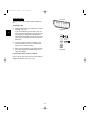
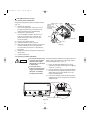
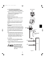
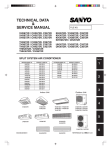
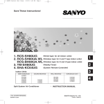
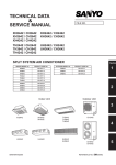
INSTALLATION INSTRUCTIONS
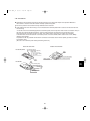
– Split System Heat Pump Air Conditioner –
X
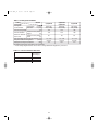
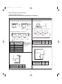
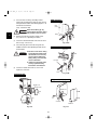
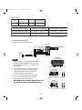
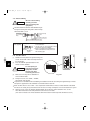
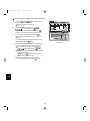
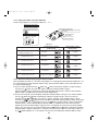
Model Combinations
K
Combine indoor and outdoor units only as listed below.
Indoor Units and Outdoor Units
Indoor Unit Type
X
K
T
U
C
30
4-Way Air Discharge XH2672R
Semi-Concealed
XHW2672R
Wall-Mounted
Ceiling-Mounted
Concealed-Duct
Outdoor Units
RC Wired Remote
(WD) Controller
RC
(WL)
26
Wireless Remote
Controller
36
42
Remarks
XH3672R
XH4272R
Optional remote controller
XHW3672R
XHW4272R
with Wired Remote Controller: RCS-TM80BG
KH2672R
KH3072R
KH3672R
Optional remote controller
KHS2672R
KHS3072R
KHS3672R
with Wireless Remote Controller: RCS-SH1UA
KHH2672R
Optional remote controller
KHHS2672R
with Wireless Remote Controller: RCS-SH1UA
TH2672R
TH3672R
TH4272R
Optional remote controller
THW2672R
THW3672R
THW4272R
with Wired Remote Controller: RCS-TM80BG
THH2672R
THH3672R
Unit with Back-up heater
THHW2672R
THHW3672R
Unit with Back-up heater
with Wired Remote Controller: RCS-TM80BG
UH2672R
UH3672R
Optional remote controller
UHW2672R
UHW3672R
with Wired Remote Controller: RCS-TM80BG
CH2672R
CH3072R
CH3672R
CH4272R
H/P
C2672R
C3072R
C3672R
C4272R
S/C
SC
Built-in type: RCS-SH80UA.WL (Optional part)
for X and T type Indoor units
External type: RCS-BH80UA.WL (Optional part)
for U type Indoor units
Built-in type: RCS-SH80UA (Accessory part / Optional part)
for K type Indoor units
Timer Remote
Controller
RCS-TM80BG* (Accessory part / Optional part)
System Controller
SHA-KC64UG (Optional part)
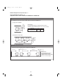
OPERATING LIMITS
Maximum Conditions
Outdoor temperature
Room temperature
Minimum Conditions
Outdoor temperature
Room temperature
/ 5°F WB
/ 59°F DB
RC
(WD)
TRC
SC
Units should be installed by licensed contractor according to
local code requirements.
* When air discharge chamber is installed.
85464359863005 ©SANYO 2007
C
* Timer Remote Controller comes with
Owner’s Manual and Installation Instructions.
Cooling
/ Heating
: 109°F DB / 65°F WB
: 71°F WB / 80°F DB
: 0°F* DB
: 57°F WB
U
RC
(WL)
RCS-SH80UG (Optional part)
for X, T and U type Indoor units.
TRC
T
SANYO Commercial Solutions
A division of SANYO North America Corporation
Cornerstone Business Park
1062 Thorndale Avenue
Bensenville, IL 60106, U.S.A.
In Canada
SANYO Canada Inc.
1-300 Applewood Crescent
Concord, Ontario
L4K 5C7, Canada
07-115 SSHP_II
5/7/07
3:59 PM
Page 2
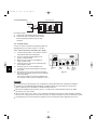
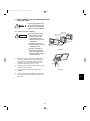
IMPORTANT!
Please Read Before Starting
When Installing…
This air conditioning system meets strict safety and operating
standards. As the installer or service person, it is an important part of your job to install or service the system so it operates safely and efficiently.
…In a Room
Properly insulate any tubing run inside a room to prevent
“sweating” that can cause dripping and water damage to
walls and floors.
For safe installation and trouble-free operation, you must:
Carefully read this instruction booklet before beginning.
Follow each installation or repair step exactly as shown.
Observe all local, state, and national electrical codes.
Pay close attention to all warning and caution notices
given in this manual.
This symbol refers to a hazard or
unsafe practice which can result
WARNING
in severe personal injury or death.
CAUTION
…In Moist or Uneven Locations
Use a raised concrete pad or concrete blocks to provide a
solid, level foundation for the outdoor unit. This prevents
water damage and abnormal vibration.
…In an Area with High Winds
Securely anchor the outdoor unit down with bolts and a
metal frame. Provide a suitable air baffle.
…In a Snowy Area (for Heat Pump-type Systems)
Install the outdoor unit on a raised platform that is higher
than drifting snow. Provide snow vents.
This symbol refers to a hazard or
unsafe practice which can result
in personal injury or product or
property damage.
When Connecting Refrigerant Tubing
If Necessary, Get Help
• Ventilate the room well, in the event that is refrigerant
gas leaks during the installation. Be careful not to allow
contact of the refrigerant gas with a flame as this will
cause the generation of poisonous gas.
These instructions are all you need for most installation
sites and maintenance conditions. If you require help for a
special problem, contact our sales/service outlet or your
certified dealer for additional instructions.
• Keep all tubing runs as short as possible.
In Case of Improper Installation
• Use the flare method for connecting tubing.
The manufacturer shall in no way be responsible for
improper installation or maintenance service, including failure to follow the instructions in this document.
• Apply refrigerant lubricant to the matching surfaces of
the flare and union tubes before connecting them, then
tighten the nut with a torque wrench for a leak-free connection.
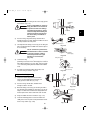
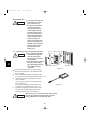
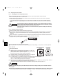
SPECIAL PRECAUTIONS
• Check carefully for leaks before starting the test run.
WARNING
When Wiring
When Servicing
• Turn the power OFF at the main power box (mains)
before opening the unit to check or repair electrical parts
and wiring.
ELECTRICAL SHOCK CAN CAUSE SEVERE
PERSONAL INJURY OR DEATH. ONLY A
QUALIFIED, EXPERIENCED ELECTRICIAN
SHOULD ATTEMPT TO WIRE THIS SYSTEM.
• Keep your fingers and clothing away from any moving
parts.
• Do not supply power to the unit until all wiring and tubing
are completed or reconnected and checked.
CAUTION
• Highly dangerous electrical voltages are used in this system. Carefully refer to the wiring diagram and these
instructions when wiring. Improper connections and inadequate grounding can cause accidental injury or death.
• Clean up the site after you finish, remembering to check
that no metal scraps or bits of wiring have been left
inside the unit being serviced.
• Ground the unit following local electrical codes.
• Ventilate any enclosed areas when installing or testing
the refrigeration system. Escaped refrigerant gas, on
contact with fire or heat, can produce dangerously toxic
gas.
• Connect all wiring tightly. Loose wiring may cause overheating at connection points and a possible fire hazard.
When Transporting
• Confirm after installation that no refrigerant gas is leaking. If the gas comes in contact with a burning stove, gas
water heater, electric room heater or other heat source,
it can cause the generation of poisonous gas.
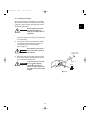
Be careful when picking up and moving the indoor and outdoor
units. Get a partner to help, and bend your knees when lifting to
reduce strain on your back. Sharp edges or thin aluminum fins
on the air conditioner can cut your fingers.
2
07-115 SSHP_II
5/7/07
3:59 PM
Page 3
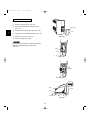
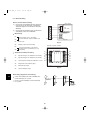
Check of Density Limit
2. The standards for minimum room volume are as
follows.
The room in which the air conditioner is to be
installed requires a design that in the event of
refrigerant gas leaking out, its density will not
exceed a set limit.
The refrigerant (R410A), which is used in the air conditioner, is safe, without the toxicity or combustibility of
ammonia, and is not restricted by laws imposed to protect the ozone layer. However, since it contains more
than air, it poses the risk of suffocation if its density
should rise excessively. Suffocation from leakage of
refrigerant is almost non-existent. With the recent
increase in the number of high density buildings, however, the installation of multi air conditioner systems is
on the increase because of the need for effective use
of floor space, individual control, energy conservation
by curtailing heat and carrying power, etc.
Most importantly, the multi air conditioner system is
able to replenish a large amount of refrigerant compared to conventional individual air conditioners. If a
single unit of the multi air conditioner system is to be
installed in a small room, select a suitable model and
installation procedure so that if the refrigerant accidentally leaks out, its density does not reach the limit
(and in the event of an emergency, measures can be
made before injury can occur).
In a room where the density may exceed the limit,
create an opening with adjacent rooms, or install
mechanical ventilation combined with a gas leak
detection device. The density is as given below.
(1) No partition (shaded portion)
(2) When there is an effective opening with the adjacent room for ventilation of leaking refrigerant gas
(opening without a door, or an opening 0.15% or
larger than the respective floor spaces at the top
or bottom of the door).
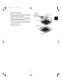
Outdoor unit
Refrigerant tubing
Indoor unit
(3) If an indoor unit is installed in each partitioned
room and the refrigerant tubing is interconnected,
the smallest room of course becomes the object.
But when mechanical ventilation is installed interlocked with a gas leakage detector in the smallest
room where the density limit is exceeded, the volume of the next smallest room becomes the object.
Refrigerant tubing
Total amount of refrigerant (oz.)
Outdoor unit
Min. volume of the indoor unit installed room (ft.3)
< Density limit (oz./ft.3)
Very
small
room
The density limit of refrigerant which is used in multi air conditioners is 0.3 oz./ft.3 (ISO 5149).
Small
room
NOTE
Medium
room
Large room
Mechanical ventilation device – Gas leak detector
1. If there are 2 or more refrigerating systems in a single refrigerating device, the amount of refrigerant
should be as charged in each independent device.
3. The minimum indoor floor space compared with the
amount of refrigerant is roughly as follows (when
the ceiling is 9 ft. high):
For the amount of charge in this example:
ft.3
Outdoor unit
430
e.g., charged
amount (33 lbs.)
376
Min. indoor floor space
e.g., charged
amount (22 lbs.)
Indoor unit
Indoor unit
Room A Room B Room C Room D Room E Room F
The possible amount of leaked refrigerant gas in rooms
A, B and C is 22 lbs.
The possible amount of leaked refrigerant gas in rooms
D, E and F is 33 lbs.
323
269
215
161
108
54
0
3
Range below the
density limit
of 0.3 oz./ft.3
(countermeasures
not needed)
Range above
the density limit
of 0.3 oz./ft.3
(countermeasures
needed)
22
44
66
Total amount of refrigerant
lbs.
07-115 SSHP_II
5/7/07
3:59 PM
Page 4
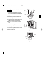
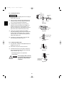
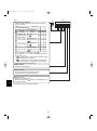
Precautions for Installation Using New Refrigerant
1. Care regarding tubing
1-1. Process tubing
Material: Use C1220 phosphorous deoxidized copper specified in JIS H3300 “Copper and Copper Alloy Seamless Pipes and Tubes.”
Tubing size: Be sure to use the sizes indicated in the table below.
Use a tube cutter when cutting the tubing, and be sure to remove any flash. This also applies to distribution
joints (optional).
When bending tubing ø5/8" or smaller, use a bending radius that is 4 times the outer diameter of the tubing or larger.
Use sufficient care in handling the tubing. Seal the tubing ends with
caps or tape to prevent dirt, moisture, or other foreign substances
from entering. These substances can result in system malfunction.
CAUTION
Unit: inch
Material
Copper tube
O
Outer diameter
1/4
3/8
1/2
5/8
Wall thickness
1/32
1/32
1/32
5/128
1-2. Prevent impurities including water, dust and oxide from entering the tubing. Impurities can cause R410A
refrigerant deterioration and compressor defects. Due to the features of the refrigerant and refrigerating
machine oil, the prevention of water and other impurities becomes more important than ever.
2. Be sure to recharge the refrigerant only in liquid form.
2-1. Since R410A is a non-azeotrope, recharging the refrigerant in gas form can lower performance and cause
defects of the unit.
2-2. Since refrigerant composition changes and performance decreases when gas leaks, collect the remaining
refrigerant and recharge the required total amount of new refrigerant after fixing the leak.
3. Different tools required
3-1. Tool specifications have been changed due to the characteristics of R410A.
Some tools for R22- and R407C-type refrigerant systems cannot be used.
Item
R407C tools
New
compatible
tool?
with R410A?
Manifold gauge
Remarks
Manifold gauge
Yes
No
Types of refrigerant, refrigerating machine oil, and
pressure gauge are different.
Charge hose
Yes
No
To resist higher pressure, material must be changed.
Vacuum pump
Yes
Yes
Use a conventional vacuum pump if it is equipped
with a check valve. If it has no check valve,
purchase and attach a vacuum pump adapter.
Leak detector
Yes
No
Leak detectors for CFC and HCFC that
react to chlorine do not function because
R410A contains no chlorine. Leak detector
for HFC134a can be used for R410A.
Flaring oil
Yes
No
For systems that use R22, apply mineral oil (Suniso oil)
to the flare nuts on the tubing to prevent refrigerant
leakage. For machines that use R407C or R410A, apply
synthetic oil (ether oil) to the flare nuts.
* Using tools for R22 and R407C and new tools for R410A together can cause defects.
4
Vacuum pump
Outlet
Inlet
07-115 SSHP_II
5/7/07
3:59 PM
Page 5
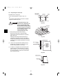
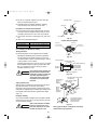
3-2. Use R410A exclusive cylinder only.
Configuration and characteristics of cylinders
When charging with a refrigerant cylinder, use an
electronic scale for charging refrigerant. In this
case, if the volume of refrigerant in the cylinder
becomes less than 20% of the fully-charged
amount, the composition of the refrigerant starts
to change. Thus, do not use the refrigerant if the
amount in the charging cylinder is less than 20%.
Valve
Also, charge the minimum necessary amount to
the charging cylinder before using it to charge the
air conditioning unit.
Liquid
Single valve
Charge liquid refrigerant with
cylinder in up-side-down position.
Fig. 1
Valve
Liquid
Single valve (with siphon tube)
Charge with cylinder in normal position.
Fig. 2
5
07-115 SSHP_II
5/7/07
3:59 PM
Page 6
CONTENTS
Page
Page
IMPORTANT! . . . . . . . . . . . . . . . . . . . . . . . . . . . . . . . . 2
Please Read Before Starting
Check of Density Limit
Precautions for Installation Using New Refrigerant
1. GENERAL . . . . . . . . . . . . . . . . . . . . . . . . . . . . . . . 8
1-1. Tools Required for Installation (not supplied)
1-2. Accessories Supplied with Outdoor Unit
1-3. Type of Copper Tube and Insulation Material
1-4. Additional Materials Required for Installation
1-5. Tubing Size
4. HOW TO INSTALL THE OUTDOOR UNIT . . . . . 56
4-1. Installing the Outdoor Unit
4-2. Drainage Work
4-3. Routing the Tubing and Wiring
2. SELECTING THE INSTALLATION SITE . . . . . . 16
2-1. Indoor Unit
2-2. Outdoor Unit
2-3. Air-Discharge Chamber for Top Discharge
2-4. Installing the Unit in Heavy Snow Areas
2-5. Precautions for Installation in Heavy Snow
Areas
2-6. Dimensions of Wind Ducting
2-7. Dimensions of Snow Ducting
5. ELECTRICAL WIRING . . . . . . . . . . . . . . . . . . . . 57
5-1. General Precautions on Wiring
5-2. Recommended Wire Length and Wire
Diameter for Power Supply System
5-3. Wiring System Diagrams
5-4. How to Connect Wiring to the Terminal
6. HOW TO INSTALL THE WIRED REMOTE
CONTROLLER (OPTIONAL PART) . . . . . . . . . . 60
6-1. Installation Site Selection
6-2. Wired Remote Controller Installation
6-3. Basic Wiring Diagram
6-4. Wiring System Diagram for Group Control
6-5. Wiring System Diagram for Multiple Remote
Controllers
6-6. How to Switch the Indoor Temperature Sensor
6-7. Trouble Diagnostics
3. HOW TO INSTALL THE INDOOR UNIT . . . . . . . 26
Concealed-Duct Type (U Type) . . . . . . . . . . . . . . 51
3-22. Required Minimum Space for Installation and
Service
3-23. Suspending the Indoor Unit
3-24. Installing the Drain Piping
3-25. Checking the Drainage
3-26. Increasing the Fan Speed
4-Way Air Discharge Semi-Concealed Type
(X Type) . . . . . . . . . . . . . . . . . . . . . . . . . . . . . . . . 26
3-1. Suspending the Indoor Unit
3-2. Preparation for Suspending
3-3. Placing the Unit Inside the Ceiling
3-4. Installing the Drain Piping
3-5. Checking the Drainage
3-6. Before Installing the Ceiling Panel
3-7. Installing the Ceiling Panel
3-8. When Removing the Ceiling Panel
for Servicing
3-9. Duct for Fresh Air
7. HOW TO INSTALL THE WIRELESS REMOTE
CONTROLLER
(ACCESSORY PART / OPTIONAL PART) . . . . . 68
7-1. Wireless Remote Controller Installation
7-2. Room Temperature Sensor Setting
7-3. Address Switches
7-4. Setting the Model Code
Wall-Mounted Type (K Type) . . . . . . . . . . . . . . . . 34
3-10. Removing the Wall Fixture from the Unit
3-11. Selecting and Making a Hole
3-12. Installing the Rear Panel on the Wall
3-13. Removing the Grille to Install the Indoor Unit
3-14. Preparing the Indoor Side Tubing
3-15. Wiring Instructions
3-16. Wiring Instructions for Inter-Unit Connections
3-17. Shaping the Tubing
3-18. Installing the Drain Hose
<RCS-SH80UA.WL>
Ceiling-Mounted Type (T Type) . . . . . . . . . . . . . . 47
3-19. Suspending the Indoor Unit
3-20. Duct for Fresh Air
3-21. Installing the Drain Piping
6
4-Way Air Discharge Semi-Concealed Type
(X Type) . . . . . . . . . . . . . . . . . . . . . . . . . . . . . . . . 70
7-5. Indicator Section Installation
7-6. Operating Controller Installation
Ceiling-Mounted Type (T Type) . . . . . . . . . . . . . . 71
7-7. Indicator Section Installation
7-8. Operating Controller Installation
7-9. Electrical Wiring
7-10. Test Run Switch
7-11. Misoperation Alarm Indicators
07-115 SSHP_II
5/7/07
3:59 PM
Page 7
Page
<RCS-BH80UA.WL>
7-12. Separate Type Signal Receiving Unit Installation
7-13. Electrical Wiring
7-14. Test Run Switch
7-15. Misoperation Alarm Indicators
7-16. Basic Wiring Diagram
7-17. Wiring System Diagram for Group Control
7-18. Wiring System Diagram for Multiple Remote Controllers
<RCS-SH1UA>
7-19. Test Run Procedure
7-20. Check Items Before the Test Run
7-21. Preparing for the Test Run
7-22. Precautions
7-23. When Setting Indoor Unit Control PCB Switch for
Wall-Mounted Indoor Unit
8. HOW TO INSTALL THE SYSTEM CONTROLLER
(OPTIONAL PART) . . . . . . . . . . . . . . . . . . . . . . . . . . . . . . . . . 85
8-1. System Controller Installation
8-2. Electrical Wiring
8-3. Address Switch Setting
8-4. Mode Setting
8-5. How to Perform Zone Registration
8-6. Connection with Other Equipment
8-7. Memory Back Up Switch
8-8. Test Run
9. HOW TO PROCESS TUBING . . . . . . . . . . . . . . . . . . . . . . . . . 97
9-1. Connecting the Refrigerant Tubing
9-2. Connecting Tubing between Indoor and
Outdoor Units
9-3. Insulating the Refrigerant Tubing
9-4. Taping the Tubes
9-5. Finishing the Installation
10. LEAK TEST, EVACUATION AND ADDITIONAL
REFRIGERANT CHARGE . . . . . . . . . . . . . . . . . . . . . . . . . 101
10-1. Leak Test
10-2. Evacuation
10-3. Charging Additional Refrigerant
10-4. Finishing the Job
11. TEST RUN . . . . . . . . . . . . . . . . . . . . . . . . . . . . . . . . . . . . . . . 104
11-1. Preparing for Test Run
11-2. Caution
11-3. Test Run Procedure
11-4. Items to Check Before the Test Run
11-5. Test Run Using the Remote Controller
11-6. Precautions
11-7. Table of Self-Diagnostic Functions and Corrections
(X, T, U, K Type)
11-8. Examples of Wiring Diagrams
7
07-115 SSHP_II
5/7/07
3:59 PM
Page 8
1. GENERAL
1-3. Type of Copper Tube and Insulation Material
This booklet briefly outlines where and how to install
the air conditioning system. Please read over the
entire set of instructions for the indoor and outdoor
units and make sure all accessory parts listed are
with the system before beginning.
Copper tubing for connecting the outdoor unit to the
indoor unit is available in kits which contain the liquid
and gas tubing, fittings and insulation. Consult your
nearest sales outlet or A/C workshop.
1-1.
1.
2.
3.
4.
5.
6.
7.
8.
9.
10.
11.
12.
13.
14.
15.
If you wish to purchase these materials separately
from a local source, you will need:
Tools Required for Installation (not supplied)
Standard screwdriver
Phillips head screwdriver
Knife or wire stripper
Tape measure
Level
Sabre saw or key hole saw
Hacksaw
Core bits
Hammer
Drill
Tube cutter
Tube flaring tool
Torque wrench
Adjustable wrench
Reamer (for deburring)
1. Deoxidized annealed copper tube for refrigerant
tubing.
2. Foamed polyethylene insulation for copper tubes
as required to precise length of tubing.
Wall thickness of the insulation should be not less
than 5/16 in.
3. Use insulated copper wire for field wiring. Wire size
varies with the total length of wiring. Refer to
Section 5. “Electrical Wiring” for details.
CAUTION
1-2. Accessories Supplied with Outdoor Unit
See Tables 1-1 to 1-9.
Table
Check local electrical codes
and regulations before
obtaining wire. Also, check
any specified instructions
or limitations.
Type
1-1
4-Way Air Discharge Semi-Concealed
1-4. Additional Materials Required for Installation
1-2
Wall-Mounted
1. Refrigeration (armored) tape
1-3
Ceiling-Mounted
1-4
Concealed-Duct
1-5
Outdoor Unit
1-6
Wired Remote Controller
1-7
Wireless Remote Controller
1-8
Timer Remote Controller
1-9
System Controller
2. Insulated staples or clamps for connecting wire
(See your local codes.)
3. Putty
4. Refrigeration tubing lubricant
5. Clamps or saddles to secure refrigerant tubing
6. Scale for weighing
8
07-115 SSHP_II
5/7/07
3:59 PM
Page 9
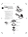
Table 1-1 XH / XHW (4-Way Air Discharge Semi-Concealed)
Part Name
Figure
Q’ty
Remarks
Full-scale installation diagram
1
For determining suspension bolt pitch
Flare insulator
2
For gas and liquid tubes
8
For suspending indoor unit from ceiling
1
For gas tube flare nuts
Hose band
2
For securing drain hose
Packing
1
For drain joint
Drain insulator
1
For drain joint
Drain hose
1
Washer
(White)
Insulating tape
Drain hose adaptor
1
For drain outlet
Sealing putty
1
For sealing recessed portion of power supply
Tube connector
1
For sizing up of liquid tube from 1/4 in. to 3/8 in.
(only for 26 type)
Wired remote controller
(comes with 7-7/8 in. wire)
1
For XHW type
Wood screws
2
For XHW type
Wire joints
2
For XHW type
Owner’s Manual
1
For XHW type
Installation Instructions
1
For XHW type
Table 1-2 KH / KHS (Wall-Mounted)
Part Name
Figure
‘Q’ty
Remarks
Wall fixture *1
1
For supporting indoor unit
Insulator *1
1
For insulation of tubing of the indoor unit
1
For securing indoor unit
20
For attaching wall fixture
1
For determining location where indoor unit is
installed
1
For supporting indoor unit
10
For attaching wall fixture
1
For improved tubing appearance
10
For attaching wall fixture
Insulator
1
For insulation of tubing of indoor unit
Tube connector
1
For sizing up of liquid tube from 1/4 in. to 3/8 in.
(only for 26 type)
*2
1
Simplifies on-site tubing work
Wireless remote controller
1
For KHS type
Wireless remote controller
mounting cradle
1
For KHS type
Truss-head tapping screws
4 × 5/8 in.
2
For KHS type
Batteries
2
For KHS type
Mounting plate
*1
Tapping screw
*1
Truss-head
Phillips
4 × 1 in.
Full-scale diagram
Wall fixture
Rawl plug
*2
*2
Cover *2
Truss-head
Phillips
4 × 5/8 in.
Tapping screw *2
L shape tube connector
*1
KH(S)3672R
*2
KH(S)3072R
KH(S)3672R
9
07-115 SSHP_II
5/7/07
3:59 PM
Page 10
Table 1-3 TH / THW (Ceiling-Mounted)
Part Name
Figure
‘Q’ty
Special washer
Drain insulator
Flare insulator
T3
T5
Drain hose adaptor
Remarks
4
For temporarily suspending indoor unit
from ceiling
1
For drain hose joint
1 Set For gas tube joints
1
Drain hose clamp
4
Black
2
For gas tube and drain hose joint
White
(heat-resisting)
1
For gas flare joints
Vinyl clamp
2
For ends of flare insulator
Full-scale installation
diagram
1
For determining suspension bolt pitch
For sealing recessed portion of power supply
Insulating tape
Sealing putty
1
Drain hose
1
Tube connector
1
For sizing up of liquid tube from 1/4 in. to 3/8 in.
(only for 26 type)
Wired remote controller
(comes with 7-7/8 in. wire)
1
For THW type
Wood screws
2
For THW type
Wire joints
2
For THW type
Owner’s Manual
1
For THW type
Installation Instructions
1
For THW type
Table1-4 UH / UHW (Concealed-Duct)
Part Name
Figure
Remarks
For gas and liquid tubes
(Black)
2
For gas and liquid tubes
(White)
2
For gas and liquid tube flare nuts
Insulating tape
Tapping screw TOTA4-10
‘Q’ty
2
Flare insulator
14 or 20 or 24 For air intake duct connection
For increasing fan speed
Jumper cable*
1
Hose band
1
For securing drain hose
Packing
1
For drain joint
Sealing putty
1
For sealing recessed portion of power supply
Drain insulator
1
For drain joint
Drain hose
1
Drain hose adaptor
1
Clamp
9
For securing drain hose & refrigerant tubing
Tube connector
1
For sizing up of liquid tube from 1/4 in. to 3/8 in.
(only for 26 type)
Wired remote controller
(comes with 7-7/8 in. wire)
1
For UHW type
Wood screws
2
For UHW type
Wire joints
2
For UHW type
Owner’s Manual
1
For UHW type
Installation Instructions
1
For UHW type
* Jumper cable is housed inside the electrical component box.
10
07-115 SSHP_II
5/7/07
Table 1-5
3:59 PM
Page 11
(Accessories for the Wired Remote Controller)
Part Name
Figure
‘Q’ty
Part Name
Figure
‘Q’ty
Wired remote controller
(comes with 7-7/8 in. wire)
1
Spacers
2
Machine screws
M4 × 1 in.
2
Wire joints
4
Wood screws
2
Table 1-6
(Accessories for the Wireless Remote Controller)
<RCS-SH80UA.WL>
Part Name
Figure
Operation controller
‘Q’ty
Part Name
Figure
‘Q’ty
1
Spacers
2
1
Pan-head tapping screws
4 × 13/32 in.
4
Wireless remote controller
1
Truss-head tapping screws
4 × 5/8 in.
2
Wireless remote controller
mounting cradle
1
Vinyl clamps
L 5-29/32
3
Batteries
2
Wire joints
4
Indicator section
Run
Timer Heating preparations
<RCS-SH1UA>
Part Name
Figure
‘Q’ty
Part Name
Figure
‘Q’ty
Wireless remote controller
1
Truss-head tapping screws
4 × 5/8 in.
2
Wireless remote controller
mounting cradle
1
Batteries
2
11
07-115 SSHP_II
5/7/07
3:59 PM
Page 12
<RCS-BH80UA.WL>
Part Name
Figure
‘Q’ty
Part Name
Figure
‘Q’ty
Separate type signal receiving unit
(comes with 7-7/8 in. wire)
1
Small screws
M4 × 1-9/16 in.
2
Carrier for ceiling installation
1
Wood screws
2
Wireless remote controller
1
Spacers
4
Wireless remote controller
mounting cradle
1
Wire joints
4
Batteries
2
Clamp
1
Machine screws
M4 × 1 in.
2
Ceiling installation paper pattern
(3-3/4 × 2-1/32 in.)
1
Table 1-7
(Accessories for the Timer Remote Controller)
Part Name
Figure
‘Q’ty
Part Name
Figure
‘Q’ty
Timer Remote Controller
1
Wood screws
2
Connecting wiring
length 4 ft.
1
Spacers
2
Machine screws
M4 × 1 in.
2
Clamps
2
Table 1-8
(Accessories for the System Controller)
Part Name
Figure
‘Q’ty
Part Name
Figure
‘Q’ty
SYSTEM CONTROLLER IDENTIFICATION LABEL
ALL Central Control
System controller
1
Label
(Identification label)
ALL RCU.
ZONE1 Central Control
ZONE1 RCU.
ZONE2 Central Control
ZONE2 RCU.
ZONE3 Central Control
ZONE3 RCU.
ZONE4 Central Control
ZONE4 RCU.
1
*Please attach this label on surface of the lid after cleaning.
*If need to write down some detail, use magic marker.
ALL ON
INPUT
Rubber bushing
(7/8 in.)
4
Label
(Terminal base label)
ALL OFF
INPUT
2
12
U2
U2 Aux.
OPERATION
STATE
OUTPUT
UNUSED
ALARM
OUTPUT
COMMON
OUTPUT
Screws for fixture
(1-3/16 in.)
U1
Interunit
control
wiring
COMMON
INPUT
DC12V
FROM
INDOOR
UNIT PCB.
1
5/7/07
3:59 PM
Page 13
1-5. Tubing Size
Single
Single type
Refrigerant tubing between the indoor and outdoor units
should be kept as short as possible.
The length of the refrigerant tubes between the indoor
and outdoor units are limited by the elevation difference
between the 2 units. During tubing work, try to make both
the tubing length (L) and the difference in elevation (H1)
as short as possible. Refer to Table 1-10.
Main tubing L
Table 1-9
Indoor unit type
26, 30, 36 types
42 type
Maximum length
165 ft.
165 ft.
Charge-less tubing length (actual length)
10 – 100 ft.
15 – 100 ft.
Additional charge per 1 ft.
Maximum indoor-outdoor
height difference
0.43 oz.
If outdoor unit is higher
H1
< 100
If outdoor unit is lower
H1
< 50
13
H1
07-115 SSHP_II
07-115 SSHP_II
5/7/07
3:59 PM
Page 14
Table 1-10 Tubing Data for Models
Models
Tubing Data
Tubing size
outer diameter
Liquid tube
Gas tube
in. (mm)
in. (mm)
Limit of tubing length
(ft.)
Outdoor unit is placed
Limit of elevation
higher
(ft.)
difference between
Outdoor unit is placed
the 2 units
lower
(ft.)
Max. allowable tubing length at shipment (ft.)
Required additional refrigerant *1
(oz./ft.)
Refrigerant charged at shipment
(lbs.)
C(H)2672R
C(H)3072R
C(H)3672R
C(H)4272R
3/8 (9.52)
5/8 (15.88)
165
3/8 (9.52)
5/8 (15.88)
165
3/8 (9.52)
5/8 (15.88)
165
100
100
100
50
50
50
10 – 100
a) 0.43
4.2
10 – 100
b) 0.43
6.2
10 – 100
b) 0.43
7.9
No additional charge of compressor oil is necessary.
*1 If total tubing length becomes 100 to 165 ft., charge additional refrigerant by 0.43 oz./ft.
Table 1-11 List of Connection Tube Sizes
Main tubing (L)
Type capacity of indoor units
Gas tube
Liquid tube
Amount of additional charge per 1 ft.
26 – 42
ø5/8"
ø3/8"
0.43 oz.
14
07-115 SSHP_II
5/7/07
3:59 PM
CAUTION
Page 15
1. This unit requires no additional refrigerant charge up to 100 ft. tubing length.
In case of more than 100 ft., additional
refrigerant charge is required. Refer to
Table 1-11.
2. In case of multi type installation,
indoor units should be installed within
the same room. If multi type indoor
units are installed in different rooms,
temperature control may develop problems because thermostat operation
must follow the thermostat condition of
1 indoor unit only (the main unit).
WARNING
Always check the gas density
for the room in which the unit is
installed.
Check of limit density
(Min indoor volume where the indoor unit is installed: ft.3)
< Limit density 0.3 (oz./ft.3)
The limit density of refrigerant which is used in this unit
is 0.3 oz./ft.3 (ISO 5149).
The shipped outdoor unit comes charged with the
amount of refrigerant fixed for each type; so add it to
the amount that is charged at the field. (For the refrigerant charge amount at shipment, refer to the unit’s
nameplate.)
ft.2
538
ft.3
4,842
484
4,356
430
3,870
376
3,384
323
269
215
161
Min. indoor volume
(Total refrigerant charged amount: oz.)
Minimum indoor volume & floor area relative to
the amount of refrigerant is roughly as given in
the following table.
Min. indoor floor area
(when the ceiling is 9 ft. high)
When installing an air conditioner in a room, it is necessary to ensure that even if the refrigerant gas accidentally escapes, its density does not exceed the limit level.
If the density might exceed the limit level, it is necessary to set up an opening between it and the adjacent
room, or to install mechanical ventilation which is interlocked with the leak detector.
2,907
2,421
1,935
1,449
108
972
54
486
CAUTION
15
Range below the
density limit of
0.3 oz./ft.3
(Countermeasures
not needed)
Range above the
density limit of
0.3 oz./ft.3
(Countermeasures
needed)
22
44
66
Total amount of refrigerant
88 lbs.
Pay special attention to any
location, such as a basement
or recessed area, etc. where
leaked refrigerant can collect,
since refrigerant gas is heavier than air.
07-115 SSHP_II
5/7/07
3:59 PM
Page 16
2. SELECTING THE INSTALLATION SITE
Ceiling-Mounted Type
2-1. Indoor Unit
Ceiling
AVOID:
areas where leakage of flammable gas may be
expected.
places where large amounts of oil mist exist.
direct sunlight.
locations near inverter lamps which may affect the
performance of the unit.
locations near heat sources which may affect the
performance of the unit.
Wall
Min. 10 inch
locations where the remote controller will be splashed
with water or affected by dampness or humidity.
installing the remote controller behind curtains or
furniture.
locations where the receiver in the indoor unit is
exposed to the inverter lamp light. Faulty operation of
the unit occurs.
Min. 10 inch
NOTE
The rear of the indoor unit can be installed flush
against the wall.
Ceiling
Air
discharge
locations where external air may enter the room
directly. This may cause “sweating” on the air discharge ports, causing them to spray or drip.
Front view
Air intake
Min. 2 ft.
Side view
Max 25 cm
4-Way Air Discharge Type
Concealed-Duct Type
DO:
select an appropriate position from which every
corner of the room can be uniformly cooled.
select a location where the ceiling is strong enough
to support the weight of the unit.
select a location where tubing and drain pipe have
the shortest run to the outdoor unit.
allow room for operation and maintenance as well as
unrestricted air flow around the unit.
3 ft.
3 ft.
3 ft.
3 ft.
3 ft.
Wall-Mounted Type
install the unit within the maximum elevation
difference above or below the outdoor unit and within
a total tubing length (L) from the outdoor unit as
detailed in Table 1-11.
Min.
6 inch
Min.
6 inch
allow room for mounting the remote controller about
3 ft. off the floor, in an area that is not in direct
sunlight nor in the flow of cool air from the indoor
unit.
NOTE
Air delivery will be degraded if the distance from the
floor to the ceiling is greater than 10 ft.
16
Min.
12 inch
07-115 SSHP_II
5/7/07
3:59 PM
Page 17
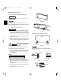
2-2. Outdoor Unit
AVOID:
Exhaust fan
heat sources, exhaust fans, etc. (Fig. 2-1)
damp, humid or uneven locations
Hot air
Heat source
DO:
Outdoor
unit
choose a place as cool as possible.
choose a place that is well ventilated and outside
air temperature does not exceed maximum 115°F
constantly.
allow enough room around the unit for air intake/
exhaust and possible maintenance. (Fig. 2-2)
use lug bolts or equal to bolt down unit, reducing
vibration and noise.
if cooling operation is to be used when the outdoor
air temperature is 23°F or below, install a duct on
the outdoor unit.
Fig. 2-1
Installation space
(Obstruction above unit)
Distance between obstructions and the unit air inlet
and outlet must be as shown below.
Air direction chamber
(field supply)
*3
B
A
Inlet side C
More than 25/64"
More than 25/64"
*2
Inlet side
More than 8"
*1
*4
(Obstruction on
inlet side)
Outlet side
More than
3.3 ft.
(Ground)
*1
Fig. 2-2
CAUTION
Fig. 2-3
Concerning inlet-side distance “C” (Fig. 2-2)
The minimum for distance “C” is 6" if there are no obstructions on the outlet side
(wall *1 side) and *2 or *4 is not present. In all other cases, the minimum for distance
“C” is 8".
If the unit is installed with the outlet side facing wall *1, then there must be no obstructions on 2 of the remaining 3 sides: *2, *3, *4.
If wall *1 is on the outlet side (Fig. 2-2), or if obstructions are present on all 3 sides *2,
*3, and *4 (Fig. 2-2), then the minimum distance for “A” and “B” is 80" (Fig. 2-3). Even
if there is no wall on the outlet side, a minimum of 3.3 ft. is required.
Installation requirements
provide a solid base (concrete block, 4" × 16"
beams or equal), a minimum of 6" above ground
level to reduce humidity and protect the unit against
possible water damage and decreased service life.
(Fig. 2-4)
use lug bolts or equal to bolt down unit, reducing
vibration and noise.
Anchor bolts
(4 pieces)
Fig. 2-4
17
07-115 SSHP_II
5/7/07
3:59 PM
Page 18
2-3. Air-Discharge Chamber for Top Discharge
Be sure to install an air discharge chamber in the
field when:
Air discharge
it is difficult to keep a space of min. 20" between
the air discharge outlet and an obstacle.
Air discharge
the air discharge outlet is facing a sidewalk and
discharged hot air may bother passers-by.
Refer to Fig. 2-5.
2-4. Installing the Unit in Heavy Snow Areas
In locations with strong wind, snow-proof ducting
should be fitted and direct exposure to the wind
should be avoided as much as possible.
Fig. 2-5
Countermeasures against snow and wind
In regions with snow and strong wind, the following
problems may occur when the outdoor unit is not provided with a platform and snow-proof ducting:
In regions with significant snowfall, the outdoor unit should
be provided with a platform and snow-proof duct.
a) The outdoor fan may not run and damage to the
unit may occur.
b) There may be no air flow.
c) The tubing may freeze and burst.
d) The condenser pressure may drop because of
strong wind, and the indoor unit may freeze.
2-5. Precautions for Installation in Heavy Snow
Areas
(1) The platform should be higher than the max. snow
depth. (Fig. 2-6)
Without snowproof ducting
(Low platform)
(2) The 2 anchoring feet of the outdoor unit should be
used for the platform, and the platform should be
installed beneath the air intake side of outdoor
unit.
With snowproof ducting
(High platform)
Fig. 2-6
Outdoor
Unit
(3) The platform foundation must be firm and the unit
must be secured with anchor bolts.
(4) In case of installation on a roof subject to strong
wind, countermeasures must be taken to prevent
the unit from being blown over.
Duct
Air
Intake
Fig. 2-7
18
07-115 SSHP_II
5/7/07
3:59 PM
Page 19
2-6. Dimensions of Wind Ducting
Reference diagram for air-discharge chamber (field supply)
STK–DRV80U for 2672R / 3072R / 3672R unit
ole
2h
Air discharge chamber
2
Air discharge chamber (base)
/3
ø5
3-
9-27/32
1
2
21-13/16
ole
4h
/6
15
(25/32) (25/32)
(25/32)
6-ø
23-15/32
22-7/16
21-39/64
1
Rectangular hole
(both sides)
5-3/16
(25/32)
2
5-5/32
9-27/32
9-27/32
1-1/16
21-13/16
15/16 17/32
Unit: inch
Note: In snowy regions, if there is concern that snow may enter the air discharge
chamber, remove the base of the chamber (10 screws) before using.
Unit light side, air discharge chamber
4
Reinforcement brackets, 4 locations
9-7/16
3
4
9-7/16
1
22-13/32
21-13/32
19
1
1-1/8
21-5/32
42-29/32
39-1/4
9-27/32
Rectangular
hole
Rectangular
hole
9-27/32
12-7/32
2-3/4
Rectangular
hole
21-5/32
9-27/32
1-3/8
1
12-15/32
1-1/8
2
1-3/8
Unit left side, air discharge chamber
3
12-15/32
Unit front, air discharge chamber
2
2-3/4
1
11-13/16
STK-DRE140A for 4272R unit
Rectangular
hole
Unit: inch
07-115 SSHP_II
5/7/07
3:59 PM
Page 20
Dimensions of Outdoor Unit with air-discharge chamber (field supply)
2672R / 3072R / 3672R unit with STK-DRV80U
13/32
Win
d
dire
ctio
n
1/2
2-17/32
15-15/16
14-31/32
19/32
1/2
25/32
Wind direction
1/2
13-3/8
4-5/16
25-31/32
25/32
6-11/16
21-13/16
37
4-1/16
9-27/32
Wind direction
5-3/16
21-5/8
23/32
Wind direction
Wind direction
30-23/32
Wind direction
Unit: inch
25/32
13/32
14-31/32
1/2
25/32
4-5/16
Win
dire d
ctio
n
1/2
11-13/16
13-3/8
1/2
25-31/32
Wind direction
19/32
6-11/16
21-13/32
11-13/16
4-1/4
2-11/36
37
Wind
direction
15-15/16
4272R unit with STK-DRE140A
Wind direction
Wind
direction
48-7/16
39-1/4
Wind direction
Wind
direction
23/32
Wind
direction
Unit: inch
20
07-115 SSHP_II
5/7/07
3:59 PM
Page 21
Reference diagram for air-discharge chamber (field supply)
C(H)2672R / 3072R / 3672R / 4272R with STK-DRV80U & DRE140A
Required space around outdoor unit
If the air discharge chamber is used, the space shown below must be secured around the outdoor unit.
If the unit is used without the required space, a protective device may activate, preventing the unit from operating.
Min. 39-3/8
Min. 7-7/8
(1) Single-unit installation
Unit: inch
CAUTION
The top and both sides must remain open. If there are obstacles to the front and rear of
the outdoor unit, the obstacle at either the front or rear must be no taller than the height of
the outdoor unit.
(2) Multiple-unit installation
More than 11-13/16
More than 11-13/16
More than 7-7/8
More than 15-3/4
Installation in lateral rows
Unit: inch
CAUTION
The front and top must remain open.
The obstacles must be no taller than the height of the outdoor unit.
Installation in front-rear rows
Installation with intakes facing outlets
Installation with intakes facing
intakes or outlets facing outlets
More than 15-3/4
More than 78-3/4
More than 59-1/16
Unit: inch
CAUTION
The front and both sides must remain open.
21
07-115 SSHP_II
5/7/07
3:59 PM
Page 22
2-7. Dimensions of Snow Ducting
Reference diagram for snow-proof vents (field supply)
STK-BDRE80A for 2672R / 3072R / 3672R unit
30-3/32
1
Unit top, snow-proof vent
2
Unit left side
3
Unit right side
4
Unit reverse side
5
Unit reverse side
6
Unit sides, reinforcement brackets for snow-proof vent
4
1
Fastened by screws at 13 locations
3-3/4
19-11/16
11-29/32
6
5
Unit anchor hole
(6 – ø7 hole)
1-21/32
Fastened by screw at 1
location (also on reverse side)
16-25/32
13-25/32
19-11/16
Fastened by screws at 3 locations
(also on reverse side)
27-29/32
9-3/16
3-31/32
9-3/8
16-25/32
9-3/16
27-29/32
17-15/32
25/32
5-3/32
25-13/32
2
5/8
28-3/4
30-11/16
Unit: inch
STK-BDR140U for 4272R unit
Fastened by screws at 13 locations
30-3/32
1
Unit top, snow-proof vent
2
Unit left side
3
Unit right side
4
Unit reverse side
5
Unit reverse side
6
Unit sides, reinforcement brackets for snow-proof vent
4
1
25-13/32
3-3/4
2
28-13/16
19-11/16
15-9/32
1-5/8
ole
rh
cho le)
n
a
o
it
Un ø7 h
–
(7
28-3/4
30-5/8
22
47-19/32
19-11/16
17-23/32
28-13/16
13-5/16
9-3/16
3-31/32
47-19/32
Fastened by screws at
3 locations (also on reverse side)
Fastened by screw at
1 location (also on reverse side)
11-7/8
19-11/16
25-32
5-29/32
17-15/32
9-3/16
3
5/8
1-13/16
Unit: inch
07-115 SSHP_II
5/7/07
3:59 PM
Page 23
Dimensions of outdoor unit with snow-proof vents (field supply)
2672R / 3072R / 3672R unit with STK-BDRE80A
13/32
15-15/16
14-31/32
19/32
11-29/32
37
Wind direction
16-3/4
Wind direction
25/32
Wind direction
7-1/16
3/4
30-3/32
Wind direction
25-13/32
Wind direction
30-23/32
Wind direction
Unit: inch
4272R unit with STK-BDR140U
Wind direction
Wind direction
15-15/16
25/32
13/32
19/32
14-31/32
25/32
25-13/32
30-3/32
7-1/16
Wind direction Wind direction
37
47-19/37
48-7/16
Wind direction
28-13/16
11-29/32
24-7/8
Wind direction
Unit: inch
23
07-115 SSHP_II
5/7/07
3:59 PM
Page 24
Reference diagram for snow-proof vents – 1
Space requirements for setting – (1)
C(H)2672R / 3072R / 3672R / 4272R with STK-BDRE80A & STK-BDR140U
[Obstacle to the front of unit]
[Obstacle to the rear of unit]
Top is open:
Top is open:
(1) Single-unit installation
Min. D
Min. A
Min. H
(1) Single-unit installation (2) Obstacles on both sides
Min. B
(2) Multiple-unit installation (2 or more units)
Min. C
Min. I
Min. G
Min. I
Min. J
(3) Multiple-unit installation (2 or more units)
Min. E
Min. E
Min. E
Min. F
Outdoor unit
Note:
In cases 2 and 3 the
height of the obstacle
must be no taller than
the height of the
outdoor unit.
C(H)2672R / 3072R /
3672R / 4872R
A
5-29/32
B
5-29/32
C
11-13/16
D
7-7/8
E
11-13/16
F
5-29/32
G
7-7/8
C(H)2672R / 3072R /
3672R / 4272R
I
19-11/16 11-13/16
J
39-3/8
Top is blocked by an obstacle:
Min. M
Top is blocked by an obstacle:
Min. N
Outdoor unit
H
Min. K
Min. L
Outdoor unit
L
K
C(H)2672R / 3072R /
3672R / 4272R
19-11/16
5-29/32
Outdoor unit
M
N
C(H)2672R / 3072R /
3672R / 4272R
39-3/8
39-3/8
Unit: inch
24
07-115 SSHP_II
5/7/07
3:59 PM
Page 25
Reference diagram for snow-proof vents – 2
Space requirements for setting – (2)
C(H)2672R / 3072R / 3672R / 4272R with STK-BDRE80A & STK-BDR140U
[Obstacles to the front and rear of unit]
The top and both sides must remain open. Either the obstacle to the front or
the obstacle to the rear must be no taller than the height of the outdoor unit.
Q
Min. O
Min. P
(1) Single-unit installation
Dimension Q
If a snow protection duct is attached after the unit is
installed, verify that dimension Q is 19-11/16 in. or more.
Outdoor unit
C(H)2672R / 3072R /
3672R / 4272R
O
P
39-3/8
5-29/32
Min. 11-13/16
Q
Min. 7-7/8
Min. 11-13/36
Min. 39-3/8
(2) Obstacles on both sides
[Installation in front-rear rows]
• The top and both sides must remain open. Either the obstacle to the front or the obstacle
to the rear must be no taller than the height of the outdoor unit.
0
Min. 11-13/16
Min. 39-3/8
Min. 59-1/16
Min. 78-3/4
Min. 7-7/8
Dimension Q
If a snow protection duct is
attached after the unit is
installed, verify that dimension
Q is 19-11/16 in. or more.
Unit: inch
25
07-115 SSHP_II
5/7/07
3:59 PM
Page 26
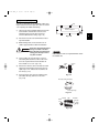
3. HOW TO INSTALL THE INDOOR UNIT
4-Way Air Discharge Semi-Concealed Type
(X Type)
3-1. Suspending the Indoor Unit
Hole-in-anchor
Hole-in-plug
This unit uses a drain pump. Use a carpenter’s level to
check that the unit is level.
Concrete
Insert
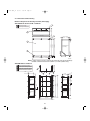
3-2. Preparation for Suspending
(1) Fix the suspension bolts securely in the ceiling
using the method shown in the diagrams (Figs. 3-1
and 3-2), by attaching them to the ceiling support
structure, or by any other method that ensures that
the unit will be securely and safely suspended.
Suspension bolt (M10 or 3/8")
(field supply)
Fig. 3-1
(2) Follow Fig. 3-2 and Table 3-1 to make the holes in
the ceiling.
Table 3-1
A (Ceiling opening)
B
(Suspension bolt pitch)
Unit: inch (mm)
B
XH(W)2672R
(PNR-XH2442)
32-9/32
(820)
22-9/32
(566)
XH(W)3672R, XH(W)4272R
(PNR-XH3642)
43-11/16
(1,110)
33-11/16
(856)
Drain hose
side
32-9/32 (Ceiling opening)
A
(3) Determine the pitch of the suspension bolts using
the supplied full-scale installation diagram. The
diagram and table (Fig. 3-3 and Table 3-2) show
the relationship between the positions of the suspension fitting, the unit, and the panel.
29-13/16 (Suspension bolt pitch)
Length
Type
X
Grille center
Refrigerant
tubing side
Unit: inch
Fig. 3-2
Drain connection (other side)
(VP25)
Refrigerant tubing joint (gas tube side)
Refrigerant tubing joint
(liquid tube side)
C
D
1-3/16
A
B
Suspension lug
E
X
Unit: inch
Fig. 3-3
Table 3-2
Unit: inch (mm)
Length
A
B
C
D
E
XH(W)2672R
(PNR-XH2442)
6-3/16
(157)
7-5/32
(182)
10-9/32
(261)
12-1/8
(308)
4-7/8
(124)
XH(W)3672R, XH(W)4272R
(PNR-XH3632)
6-3/16
(157)
7-5/32
(182)
11-15/32
(291)
13-1/16
(338)
4-7/8
(124)
Type
26
3:59 PM
Page 27
3-3. Placing the Unit Inside the Ceiling
(1) When placing the unit inside the ceiling, determine
the pitch of the suspension bolts using the
supplied full-scale installation diagram. (Fig. 3-4)
The size of the opening for the indoor unit can be
confirmed by attaching the full-scale installation
diagram beneath the unit. (Fig. 3-4)
Tubing and wiring must be laid inside the ceiling
when suspending the unit. If the ceiling is already
constructed, lay the tubing and wiring into position
for connection to the unit before placing the unit
inside the ceiling.
(2) The length of each suspension bolt must be
appropriate for a distance between the bottom of
the bolt and the bottom of the ceiling of 19/32 in.
or more as shown in Fig. 3-4.
Full-scale installation diagram
(printed on a cardboard packing)
1-7/8 inch
5/7/07
19/32 inch or more
07-115 SSHP_II
Full-scale installation
diagram
Fig. 3-4
Suspension bolt
Suspension lug
Nuts and washers
(Use above and below)
(3) Thread the 2 hexagonal nuts (field supply) and
washers onto the 4 suspension bolts as shown in
Fig. 3-5.
Use 2 sets of nuts and washers (upper and lower),
so that the unit will not fall off the suspension lugs.
(4) Remove the protective cardboard used to protect
the fan parts during transport.
Upper
Lower
Notch
Double nuts
1-7/8 inch
Fig. 3-5
(5) Adjust the distance between the unit and surface
of the ceiling. (1-7/8 in.) (Fig. 3-4)
27
X
07-115 SSHP_II
5/7/07
3:59 PM
Page 28
3-4. Installing the Drain Piping
X
Transparent part for
checking drainage
(1) Prepare standard hard PVC pipe for the drain and
use the supplied drain hose and hose band to prevent water leaks.
The PVC pipe must be purchased separately. The
transparent part allows you to check drainage.
(Fig. 3-6)
CAUTION
Packing
(supplied)
Tighten the hose clamps so
their locking nuts face upward.
(Fig. 3-6)
Hose band
(supplied)
Hard PVC pipe
(not supplied)
Drain hose
adapter
(supplied)
Drain hose
(supplied)
Fig. 3-6
Drain insulator (supplied)
(2) After checking the drainage, wrap the supplied
packing and drain pipe insulator around the pipe.
(Fig. 3-7)
NOTE
Ensure the drain pipe has a downward gradient (1/100
or more) and that there are no water traps.
Fig. 3-7
Air bleeder
CAUTION
Do not install an air bleeder tube, as this may cause
water to spray from the drain tube outlet. (Fig. 3-8)
Fig. 3-8
If it is necessary to increase the height of the drain
pipe, the section directly after the connection port
can be raised a maximum of 19-11/16 in. Do not
raise it any higher than 19-11/16 in., as this could
result in water leaks. (Fig. 3-9)
11-3/4 in. or less (as short as possible)
19-11/16 in. or less
Do not install the pipe with an upward gradient from
the connection port. This will cause drain water to
flow backwards and leak when the unit is stopped.
(Fig. 3-10)
Fig. 3-9
Do not apply force to the piping on the unit side
Upward gradient
when connecting the drain pipe. The pipe should
not be allowed to hang unsupported from its
connection to the unit. Fasten the pipe to a wall,
frame, or other support as close to the unit as
possible. (Fig. 3-11)
Fig. 3-10
Provide insulation for any drain pipe that is run
indoors.
Support
pieces
Fig. 3-11
28
07-115 SSHP_II
5/7/07
3:59 PM
Page 29
3-5. Checking the Drainage
After wiring and piping are completed, use the following procedure to check that the water will drain smoothly. For this, prepare a bucket and wiping cloth to catch
and wipe up spilled water.
WARNING
X
Do not supply power to the
unit until the tubing and
wiring to the outdoor unit are
completed.
(1) Take off the tube cover and through the opening,
slowly pour about 43 oz. of water into the drain pan
to check drainage.
(2) Do Test Run to check the drainage after completing installation. When performing Test Run, be
sure to observe the Test Run procedure.
Refer to page 105.
CAUTION
Be careful since the fan will
start turning when checking
the drainage.
5/16"(4 × 8 mm)
tapping screw
(3) After drain checking is finished, return the Operation Selector switch to the RUN position (ON position ) and remount the tube cover.
WARNING
Tube cover
To mount the tube cover, use
5/16" (4 × 8 mm) tapping
screws. Do not use long
screws as they may puncture
the drain pan and cause water
leakage.
Siphon
Fig. 3-12
29
07-115 SSHP_II
5/7/07
3:59 PM
Page 30
Ceiling Panel
CAUTION
X
Latch
Screw
Never touch or attempt to
move the air direction louver
by hand or you may damage
the unit. Instead, use the
remote control unit if you want
to change the direction or air
flow.
Air-intake grille
3-6. Before Installing the Ceiling Panel
(1) Remove the air-intake grille and air filter from the
ceiling panel. (Figs. 3-13 and 3-14)
Ceiling panel
(a) Remove the 2 screws on the latch of the airintake grille. (Fig. 3-13)
Fig. 3-13
(b) Press on the 2 latches of the air-intake grille
with your thumbs in the direction of the arrow
to open the grille. (Fig. 3-13)
Air filter
45°
(c) With the air-intake grille open about 45°,
remove the safety cord (hook on the grille
side). (Fig. 3-14)
Safety cord
(d) Pull the air-intake grille towards you to remove
it from the ceiling panel.
(2) Pull down the two panel catches on the body of
the indoor unit body. (Fig. 3-15)
Unit body
Fig. 3-14
Ceiling panel
Panel catch
Panel catch
(arrange facing downwards)
(2 locations)
Electrical
component box
Electrical
component box
Clamp
Ceiling panel wiring
connector
Screws M5 with washer
(supplied)
Air filter
Air-intake grille
Fig. 3-15
30
07-115 SSHP_II
5/7/07
3:59 PM
Page 31
3-7. Installing the Ceiling Panel
(1) Lift the ceiling panel and position it to align the
panel hook with the panel catch of the indoor unit.
NOTE
X
The ceiling panel must be mounted in the correct direction. Note that the 2 catches of the panel differ in size.
Confirm that the catches are correctly matched
between the ceiling panel and the indoor unit body.
(2) Next, check to see that the ceiling panel is properly aligned with the seamline of the ceiling. If it is
not, remove the ceiling panel and slightly readjust
the indoor unit body to the proper suspension
point.
(3) When the ceiling panel has been properly aligned,
use the supplied 4 mounting screws (M5) with
washers to permanently fasten the ceiling panel.
(4) Install the wiring connector from the ceiling panel
to the connector in the electrical component box of
the indoor unit. After installing the connector, use
the clamp on the body of the indoor unit to secure
the wiring.
(5) Install the air filter and air-intake grille by performing the steps in section 3-6 in reverse.
NOTE
Rehook the safety cord before closing the air-intake
grille.
3-8. When Removing the Ceiling Panel
for Servicing
When removing the ceiling panel for servicing, remove
the air-intake grille and air filter, disconnect the wiring
connector inside the electrical component box, and then
remove the 4 mounting screws.
31
07-115 SSHP_II
5/7/07
3:59 PM
Page 32
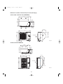
3-9. Duct for Fresh Air
For fresh air intake
There is a duct connection part on side of the indoor
unit. (Fig. 3-16)
An optional air-intake plenum (including duct connection
CMB-GSJ80U
CMB-GSJ140U
ø1
/8
Type
PNR-XH2442
(XH(W)2672R)
PNR-XH3642
(XH(W)3672R, XH(W)4272R)
4-
Air-intake plenum
ho
le
box and flange) can be attached to the indoor unit.
2-3/8
X
ø4
-1
3
/32
2-5/32
(1) Accessories
Detail of fresh air intake
Check that the following parts are in the box when
Unit: inch
Fig. 3-16
unpacking.
Name
ʻQʼty
Remarks
Cord with socket
(9P)
1
Connecting line. Not necessary for
intaking fresh air.
Screw
(M5 × L5 in.)
4
Air-intake filter
(for fastening)
Screw
(M4 × L1/2 in.)
7
Duct connection flange / box
(for fastening)
Duct connection box
1
(for fresh air)
Duct connection flange
1
(for connecting fresh air duct)
(2) Installation
Installation steps (a) to (d) are the same for both the
Installation
screws
Socket cover
CMB-GSJ80U and the CMB-GSJ140U. The figure
illustrates installation of air-intake plenum to the
indoor unit. (Fig. 3-17)
Panel lead wire (8P)
(a) Installing the air-intake plenum
Set the air-intake plenum to the indoor unit taking care
not to set it in the wrong direction. (Fig. 3-17)
Clamper
Fasten the air-intake plenum with the accessory screws.
Air-intake
plenum
(M5 × L5 in., 4 pcs) (Fig. 3-17)
8P socket (red)
(electrical
component box)
(b) Installing the duct connection box
Fasten the duct connection flange to the duct connec-
8P socket (red)
(ceiling panel side)
tion box with the accessory screws.
(M4 × L1/2 in., 4 pcs) (Fig. 3-18)
Put the duct connection box into the rectangular hole of
the air-intake plenum and fasten it to both sides of the
indoor unit and plenum with the accessory screws.
(M4 × L1/2 in., 3 pcs) (Fig. 3-18)
(c) Installing the indoor unit
Indoor unit
Install the indoor unit to the ceiling. (Install the indoor
unit according to items 3-1 to 3-6.)
CAUTION
When installing in a preexisting location, install the
indoor unit before installing
the duct connection box.
Fig. 3-17
32
07-115 SSHP_II
5/7/07
3:59 PM
Page 33
(d) Installing the ceiling panel
Duct
connection
flange
Attach the ceiling panel to the chamber. Drawing the
panel downwards sets the panel in position temporarily
with the panel catch (at 2 locations).
Duct connection box
Installation screws
(M4 × 1/2 in.)
Remove the socket cover of the air-intake plenum and
X
pass the 8P sockets through it. (Fix the panel lead wire
with the chamber side clamp.) (Fig. 3-17)
Connect the 8P socket (electrical component box side)
Panel catch
to the 8P socket (ceiling panel side) of the indoor unit
electrical component box.
Reattach the socket cover.
Ceiling panel
Fig. 3-18
33
07-115 SSHP_II
5/7/07
3:59 PM
Page 34
Wall-Mounted Type (K Type)
3-10. Removing the Wall Fixture from the Unit
KH(S)2672R
Remove and discard the set screws and take off the
rear panel. (Fig. 3-19)
Set screws for transportation only
NOTE
Fig. 3-19
K
Tubing can be extended in 3 directions as shown in
Fig. 3-20. Select the direction that provides the shortest
run to the outside unit.
Right-rear
tubing
(recommended)
Left-rear tubling
3-11. Selecting and Making a Hole
KH(S)2672R
Right tubing
(1) Remove the rear panel from the indoor unit and
place it on the wall at the location selected. Make
sure the unit is horizontal using a carpenter’s level
or tape measure to measure down from the ceiling.
Fig. 3-20
In case of left-rear or right-rear tubing
(2) Determine which side of the unit you should make
the hole. (Fig. 3-21)
(3) Before making a hole, check carefully that no studs
or pipes are directly run behind the spot to be cut.
CAUTION
Center of
left-rear
tubing hole
Also avoid areas where electrical wiring or conduits are
located.
Center of
right-rear
tubing hole
Fig. 3-21
NOTE
The above precautions are also applicable if tubing
goes through the wall in any other location.
Hole should be made at a slight downward slant to
the outdoor side.
(4) Using a sabre saw, key hole saw or hole-cutting
drill attachment, cut a hole in the wall. See Table
3-3 and Fig. 3-22.
PVC pipe (locally purchased)
Indoor
side
Outdoor
side
Table 3-3
Hole Dia. (inch)
3-3/16"
Cut at slight angle
Fig. 3-23
Fig. 3-22
(5) Measure the thickness of the wall from the inside
edge to the outside edge and cut PVC pipe at a
slight angle 1/4" shorter than the thickness of the
wall. (Fig. 3-23)
OUTSIDE
INSIDE
Wall
Plastic cover
(Field supply)
PVC pipe
Slight
angle
(6) Place the plastic cover over the end of the pipe (for
indoor side only) and insert in the wall.
(Fig. 3-24)
Fig. 3-24
34
07-115 SSHP_II
5/7/07
3:59 PM
Page 35
KH(S)3072R, KH(S)3672R
One hole is required for the air conditioner tubing, and
may be either on the left or right side. (Also see section
3-14. Preparing the Indoor Side Tubing.)
Tape
Full-scale
installation diagram
(1) Tape the full-scale installation diagram on the wall
at the location selected. Make sure the unit is
horizontal using a level or tape measure to
measure down from the ceiling. (Fig. 3-25)
Fig. 3-25
K
(2) Determine if the hole is to be drilled at the left or
right hole location.
(3) Before drilling a hole, check that there are no
studs or pipes behind the determined location.
CAUTION
Avoid any area where electrical
wiring or conduit is located.
Also take this precaution if the
tubing goes through a wall at
any other location.
NOTE
Hole should be made at a slight downward slant to
the outdoor side.
(4) Using a sabre saw, key hole saw or 3-5/32 in.
hole-cutting drill attachment, make a hole in the
wall. The required minimum hole diameter for
these models is 3-3/16 in. (Fig. 3-26)
Indoor
side
Outdoor
side
(5) Measure the thickness of the wall from the inside
edge to the outside edge and cut PVC pipe at a
slight angle 1/4 in. shorter than the thickness of
the wall. (Fig. 3-27)
(6) Place the plastic cover over the end of the pipe,
(for indoor side only) and insert in the wall.
(Fig. 3-28)
Fig. 3-26
PVC pipe (locally purchased)
Cut at slight angle
Fig. 3-27
INSIDE
Wall
Plastic
cover
OUTSIDE
PVC pipe
Slight
angle
Fig. 3-28
35
07-115 SSHP_II
5/7/07
3:59 PM
Page 36
KHH(S)2672R
Remove and discard the set screws and take off the
wall fixture. (Fig. 3-29)
Wall fixture
KHH(S)2672R
K
(1) Tape the full-scale installation diagram on the wall
at the location selected. Make sure the unit is horizontal using a level or tape measure to measure
down from the ceiling. (Fig. 3-30)
Set screws only for transportation
Fig. 3-29
Tape
Full-scale
(2) Before drilling a hole, check that there are no studs
or pipes behind the determined location.
CAUTION
Avoid any area where electrical
wiring or conduit is located.
Also take this precaution if the
tubing goes through a wall at
any other location.
installatio
n diagram
Fig. 3-30
NOTE
(3) Using a sabre saw, key hole saw or 3-5/32 in.
hole-cutting drill attachment, make a hole in the
wall. The required minimum hole diameter for
these models is 3-3/16 in. (Fig. 3-31)
Hole should be made at a slight dowward slant to the
outdoor side.
(4) Measure the thickness of the wall from the inside
edge to the outside edge and cut PVC pipe at a
slight angle 1/4 in. shorter than the thickness of
the wall. (Fig. 3-32)
Indoor
side
(5) Place the plastic cover over the end of the pipe,
(for indoor side only) and insert in the wall.
(Fig. 3-33)
Outdoor
side
Fig. 3-31
PVC pipe (locally purchased)
Cut at slight angle
Fig. 3-32
INSIDE
Wall
Plastic
cover
OUTSIDE
PVC pipe
Slight
angle
Fig. 3-33
36
07-115 SSHP_II
5/7/07
3:59 PM
Page 37
3-12. Installing the Rear Panel on the Wall
KH(S)2672R
Be sure to confirm that the wall is strong enough to suspend
the unit.
See either Item a) or b) below depending on the wall type.
a) If Wooden Wall
Fig. 3-34
(1) Attach the rear panel to the wall with the 10 screws provided. (Fig. 3-34)
If you are not able to line up the holes in the rear panel
with the beam locations marked on the wall, use toggle
bolts to go through the holes on the panel or drill 3/16 in.
dia. holes in the panel over the stud locations and then
mount the rear panel.
(2) Double-check with a ruler or carpenter’s level that the
panel is level. This is important to install the unit properly.
(Fig. 3-35)
(3) Make sure the panel is flush against the wall. Any space
between the wall and unit will cause noise and vibration.
K
Fig. 3-35
1-3/16" or more
3/16"
dia. hole
b) If Block, Brick, Concrete or Similar Type Wall
Make 3/16" dia. holes in the wall. Insert rawl plugs for appropriate mounting screws. (Fig. 3-36)
KH(S)3072R, KH(S)3672R
Rawl plug
(Field supply)
Fig. 3-36
Confirm that the wall is strong enough to support the unit.
a) If Wooden Wall
Wall fixture
(1) Attach the wall fixture to the wall with the 12 screws provided. (Fig. 3-37) If you are not able to line up the holes in
the wall fixture with the beam locations marked on the
wall, use rawl plugs or toggle bolts to go through the holes
on the panel or drill 3/16 in. dia. holes in the wall fixture
over the stud locations.
(2) Check with a tape measure or carpenter’s level that the
wall fixture is level. This is important so that the unit is correctly installed.
(3) Make sure the wall fixture is flush against the wall. Any
space between the wall and unit will cause noise and
vibration.
b) If Block, Brick, Concrete or Similar Type Wall
Make 3/16 in. dia. holes in the wall. Insert rawl plugs for
appropriate mounting screws. (Fig. 3-36)
37
Fig. 3-37
07-115 SSHP_II
5/7/07
3:59 PM
Page 38
KHH(S)2672R
wall fixture
Confirm that the wall is strong enough to support the
unit.
a) If Wooden Wall
K
(1) Attach the wall fixture to the wall with the 9 screws
provided. (Fig. 3-38)
If you are not able to line up the holes in the wall
fixture with the beam locations marked on the wall,
use rawl plugs or toggle bolts to go through the
holes on the panel or drill 13/64 in. dia. holes in the
panel over the stud locations and then mount the
wall fixture.
Fig. 3-38
3/16 in.
dia. hole
(2) Check with a tape measure or carpenter’s level
that the wall fixture is level. This is important so
that the unit is correctly installed.
Rawl plug
(3) Make sure the wall fixture is flush against the wall.
Any space between the wall and unit will cause
noise and vibration.
Fig. 3-39
b) If the Wall is Brick, Concrete or Similar
Drill 3/16 in. dia. holes in the wall. Insert rawl plugs for
appropriate mounting screws. (Fig. 3-39)
38
07-115 SSHP_II
5/7/07
3:59 PM
Page 39
3-13. Remove the Grille to Install the Indoor Unit
Grille
Air-intake grille
KH(S)2672R
Basically, these models can be installed and wired
without removing the grille. If access to any internal
part is needed, follow the steps given below:
How to remove the grille
K
(1) Set the 2 flaps in the horizontal position.
Fig. 3-40a
(2) Unscrew the 3 screws. (Fig. 3-40a)
Air-intake grille
(3) Remove the grille.
(a) Hold both corners of the air intake grille, then
pull out and up to open. (Fig. 3-40b)
(b) Use a standard screwdriver to push up the 3
tabs to remove the grille. (Fig. 3-40b)
(c) Pull the lower part of the grille toward you to
remove. (Fig. 3-40a)
Fig. 3-40b
How to replace the grille
(1) Close the flaps.
(2) Reinstall the grille into the lower part while aligning
its tabs on the upper part. (Fig. 3-41a) Insert the
tabs in the slots and push the lower part of the
grille back into position.
(3) Press at each of the 5 tabs to completely close the
grille. Make sure that the grille and frame are firmly
fitted together. (Fig. 3-41b)
Fig. 3-41a
Fig. 3-41b
39
07-115 SSHP_II
5/7/07
4:00 PM
Page 40
KH(S)3072R, KH(S)3672R
How to Remove the Grille
(1) Remove the plastic cover. (Fig. 3-42)
(2) Remove the clamp for the wiring connector.
(Fig. 3-43)
Plastic cover
(3) Disconnect the 2 wiring connectors. (Fig. 3-44)
Screw
K
(4) Set the flap in the horizontal position. (Fig. 3-45)
Fig. 3-42
(5) Remove the 3 screws. (Fig. 3-45)
(6) Remove the grille. (Fig. 3-45)
NOTE
When replacing the grille, be careful not to crush the
lead wires between the grille and the frame.
(Fig. 3-45)
Clamp
Screw
Fig. 3-43
Wiring
connectors
Fig. 3-44
Grille
Frame
Flap
Screws
Fig. 3-45
40
07-115 SSHP_II
5/7/07
4:00 PM
Page 41
Frame
3-14. Preparing the Indoor Side Tubing
KH(S)2672R
Right tubing
outlet
Arrangement of tubing by directions
(a) Right tubing
The corner of the right frame needs to be cut by
a hacksaw or the like. (Fig. 3-46)
Fig. 3-46
Tab
Mounting slot
K
(b) Right-rear or left-rear tubing
In this case, the corner of the frame need not be
cut.
To mount the indoor unit on the rear panel:
(a) Hang the 3 mounting slots of the unit on the
upper tabs of the rear panel. (Fig. 3-47)
Fig. 3-47
KH(S)3072R, KH(S)3672R
Tubing
from the
outdoor
unit
Tubing can be extended in 4 directions as shown in
Fig. 3-54.
Arrangement for Right-rear Tubing
(a) Remove the 2 screws and slide out the side
cover. (Fig. 3-48)
Fig. 3-49
Fig. 3-48
(b) Extend the gas tube from the outdoor side and
connect it directly to the mating tube inside the
indoor unit. Use a flare nut. (Fig. 3-49)
Hacksaw
Arrangement for Right Tubing
(a) Remove the 2 screws and take off the side cover.
(Fig. 3-48)
Fig. 3-50
(b) Cut out the L-shaped tubing outlet using a
hacksaw. (Fig. 3-50)
Indoor unit
(c) Using the L-shaped tube (field supply),
connect tubing between the indoor and
outdoor units. (Fig. 3-52)
Left
side
cover
Arrangement for Left and Left-rear Tubing.
(a) Remove the 4 screws (2 on each side) and take
off both left and right side cover.
(Fig. 3-51)
Bottom
cover
Right
side
cover
Fig. 3-51
(b) Remove 4 screws to remove the bottom cover.
L-shaped
tube
(c) Using the L-shaped tube (field supply), connect
tubing as in Fig. 3-53.
L-shaped tube
Fig. 3-52
41
Fig. 3-53
07-115 SSHP_II
5/7/07
4:00 PM
Page 42
KHH(S)2672R
Tubing can be extended in 4 directions as shown in
Fig. 3-54.
Left
tubing
Right-rear
tubing
(Recommended)
Left-rear
tubing
Arrangement for Left Tubing
(a) Cut out the left tubing outlet. (Fig. 3-55)
Right tubing
Arrangement for Right Tubing
K
Fig. 3-54
(a) Cut out the right tubing outlet using a hacksaw.
(Fig. 3-56)
Arrangement for Left-rear and Right-rear Tubing
Right tubing
outlet
(a) It is not necessary to cut a hole.
Left tubing
outlet
3-15. Wiring Instructions
General Precautions on Wiring
Fig. 3-55
(1) Before wiring, confirm the rated voltage of the
unit as shown on its nameplate, then carry out
the wiring closely following the wiring diagram.
(2) Provide a power outlet to be used exclusively for
each unit. A power supply disconnect and circuit
breaker for overcurrent protection should be
provided in the exclusive line.
(3) To prevent possible hazards from insulation
failure, the unit must be grounded.
(4) All wiring must be connected tightly.
(5) Do not allow wiring to touch refrigerant tubing,
compressor, or any moving parts of the fan.
Unauthorized changes in the
internal wiring can be very
dangerous. The manufacturer
will accept no responsibility for
any damage or misoperation
that occurs as a result of such
unauthorized changes.
42
Fig. 3-56
07-115 SSHP_II
5/7/07
4:00 PM
Page 43
3-16. Wiring Instructions for Inter-Unit Connections
Rear
panel
KH(S)2672R
(1) Insert the inter-unit wiring (according to local
electrical codes) into the through-the-wall PVC
pipe. Run the wiring toward the indoor side allowing
approx. 10 inches to extend from the wall face.
(Fig. 3-57)
Wall
Plastic
cover
Wiring
(2) Route the inter-unit wiring from the back of the
indoor unit and pull it toward the front for
connection. (Figs. 3-58a and 3-58b)
K
10 in.
Fig. 3-57
(3) Connect the inter-unit wiring to the corresponding
terminals on the terminal plate (Figs. 3-58a and
3-58b) while referring to the wiring diagram.
Terminal
plate
(4) Be sure to secure the wiring with the provided
clamp.
How to remove the cover plate
To access the terminal plate inside the indoor unit,
follow these steps.
(1) Using a Phillips screwdriver, remove the screw on
the cover plate. (Figs. 3-58a and 3-58b)
Cover plate
(2) Remove the cover plate.
Fig. 3-58a
Inter-unit
control line
wiring
Earth
plate
Lock nut
Top of conduit
connector
Fig. 3-58b
43
07-115 SSHP_II
5/7/07
4:00 PM
Page 44
(1) Insert the inter-unit wiring (according to local
codes) into the through-the-wall PVC pipe. Run the
wiring toward the indoor side allowing approx. 5" to
extend from the wall face.
(Figs. 3-59a and 3-59b)
CAUTION
K
KHH(S)2672R
Rear
panel
Wall
Plastic
cover
Never fix the wiring by any
means before the indoor unit is
fully seated on the rear panel.
Wiring
(2) Remove the side cover and the metallic cover.
(Fig. 3-60 or 3-61, depending on model.)
5"
(3) Secure the conduit connector to the chassis with a
lock nut. (Fig. 3-60 or 3-61)
Fig. 3-59a
(4) Give some play to the inter-unit wiring from the
outdoor unit to the corresponding terminals on the
terminal plate.
CAUTION
KH(S)3072R, KH(S)3672R
Wall fixture
Be sure to refer to the wiring
system diagram label inside
the metallic cover and carry
out the correct field wiring.
Wrong wiring can cause the
unit to malfunction.
Wall
Connector
Wiring
Check local electrical codes
and any specified wiring
instructions or limitations.
(5) Secure the metallic cover with its screw. Then
replace the side cover.
5"
Fig. 3-59b
KHH(S)2672R
KH(S)3072R, KH(S)3672R
Lock
nut
Metallic cover
Plastic cover
Metallic cover
Screw
Power line
Lock
nut
Grounding
line
Look nut
Connector
Elbow
conduit
Side cover
Fig. 3-61
Fig. 3-60
44
07-115 SSHP_II
5/7/07
4:00 PM
Page 45
KHH(S)2672R
Cover
(1) Shape the refrigerant tubing so that it can easily go into
the wall hole. (Fig. 3-62)
CAUTION
Refrigerant
tubing
If using a stepladder, be careful to
keep your balance and not fall off.
To prevent the unit from damage
and avoid personal injury, ask for
someone’s help when feeding the
tubing through the hole because
the unit is heavy and difficult to
hold in place.
Inter-unit
wiring
Drain hose
K
Fig. 3-62
b
(2) Push the wiring, refrigerant tubing, and drain hose
through the hole in the wall. Adjust the indoor unit so it is
securely seated on the rear panel.
a
b / a = 0.7 or more
Pipe bending tool
(3) Carefully bend the tubing (if necessary) to run along the
wall in the direction of the outdoor unit and then tape as
far as the fittings.
CAUTION
Fig. 3-63
The air conditioner’s performance
will deteriorate if a tube is crushed.
To prevent crushing of tubing,
avoid sharp bends. Use a pipe
bending tool to bend tubes.
(Fig. 3-63)
Insulation
(Field supply)
Fig. 3-64
Refrigerant tubing
(4) Connect the refrigerant tubing to the outdoor unit. (After
performing a leak test on the connecting part, insulate it
with tubing insulation. (Fig. 3-64)) Also, refer to Section
10-5. Connecting Tubing between Indoor and Outdoor
Units.
Conduit
(5) Assemble the refrigerant tubing, drain hose, and
inter-unit wiring as shown in Fig. 3-65.
Drain hose
Inter-unit wiring
Fig. 3-65
KH(S)3072R, KH(S)3672R
Liquid
tube
(1) Shape the narrow refrigerant tube and drain
hose in the desired direction so that they can
easily go into the wall hole. (Fig. 3-66)
Wall
Indoor
unit
(2) Push the wiring, narrow tube, and drain hose
through the hole in the wall.
Drain hose
(3) Bend the tubing (if necessary) to run along the wall in
the direction of the outdoor unit, then tape as far as the
fittings. The drain hose should come straight down the
wall to a point where water runoff won't stain the wall.
(4) Hang the indoor unit on the wall fixture. (Fig. 3-67)
(5) Install the mounting plate to secure the indoor unit
solidly to the wall. The plate can be positioned in either
of the 2 ways shown. (Fig. 3-68)
Fig. 3-67
Fig. 3-66
Mounting plate
Or
Screws
Fig. 3-68
45
Wall fixture
07-115 SSHP_II
5/7/07
4:00 PM
Page 46
Cover
3-17. Shaping the Tubing
KHH(S)2672R
Refrigerant
tubing
(1) Shape the refrigerant tubing so that it can easily go
into the hole. (Fig. 3-69)
K
Inter-unit
wiring
(2) Push the wiring, refrigerant tubing and drain hose
through the hole in the wall. Adjust the indoor unit
so it is securely seated on the wall fixture.
Drain hose
Fig. 3-69
(3) Carefully bend the tubing (if necessary) to run
along the wall in the direction of the outdoor unit
and then insulate to the end of the fittings. The
drain hose should come straight down the wall to a
point where water runoff will not stain the wall.
Insulating
tape
(4) Connect the refrigerant tubing to the outdoor
unit.(After performing a leak test on the connection,
insulate it with insulating tape. (Fig. 3-70)) Also,
refer to Section 10-5. Connecting Tubing between
Indoor and Outdoor Units.
Fig. 3-70
Refrigerant tubing
Inter-unit wiring
(5) Assemble the refrigerant tubing, drain hose and
inter-unit wiring as shown in Fig. 3-71.
Drain hose
Fig. 3-71
3-18. Installing the Drain Hose
(1) The drain hose should be slanted downward on the
outdoor side. (Fig. 3-72)
Slant
(2) Never form a trap in the course of the hose.
Indoor
unit
(3) If the drain hose will run in the room, insulate* the
hose so that chilled condensation will not damage
furniture or floors. (Fig. 3-73)
Drain
hose
Fig. 3-72
* Foamed polyethylene or its equivalent is
recommended.
WARNING
Condensation
Do not supply power to the unit
or operate it until all tubing and
wiring to the outdoor unit are
completed.
Insulation material
(field supply)
must be used.
Fig. 3-73
46
07-115 SSHP_II
5/7/07
4:00 PM
Page 47
Ceiling-Mounted Type (T Type)
Front face
3-19. Suspending the Indoor Unit
(1) Place the full-scale diagram (supplied) on the
ceiling at the spot where you want to install the
indoor unit. Use a pencil to mark the drill holes.
(Fig. 3-74).
Rear
Full-scale diagram
Fig. 3-74
NOTE
Since the diagram is made of paper, it may shrink or
stretch slightly because of high temperature or
humidity. For this reason, before drilling the holes
maintain the correct dimensions between the markings.
Hole-in-anchor
Hole-in-plug
Concrete
Insert
T
(2) Drill holes at the 4 points indicated on the full-scale
diagram.
Suspension bolt (M10 or 3/8")
(field supply)
(3) Depending on the ceiling type:
Fig. 3-75
(a) Insert suspension bolts as shown in Fig. 3-75.
or
Ceiling tiles
Ceiling support
(b) Use existing ceiling supports or construct a
suitable support as shown in Fig. 3-76.
It is important that you use
extreme care in supporting the
indoor unit from the ceiling.
Ensure that the ceiling is
sufficiently strong enough to
support the weight of the unit.
Before hanging the ceiling unit,
test the strength of each
attached suspension bolt.
(4) Screw in the suspension bolts, allowing them to
protrude from the ceiling as shown in Fig. 3-76.
The distance of each exposed bolt must be of
equal length within 2 inches. (Fig. 3-77)
A
A
Fig. 3-76
unit
Ceiling
surface
Fixture
Fig. 3-77
47
Within 2 in.
WARNING
07-115 SSHP_II
5/7/07
4:00 PM
Page 48
(5) Before suspending the indoor unit, remove the 2
screws on the latch of the air-intake grilles, open
the grilles, and remove them by pushing the claws
of the hinges as shown in Fig. 3-78. Then remove
both side panels sliding them along the unit toward
the front after removing the two screws which fix
them. (Fig. 3-79)
Pull out the
air-Intake grille
pushing claws
of the hinges
Screw
Hinge
Latch
de
Sli
(6) Preparation for suspending the indoor unit. The
suspension method varies depending on whether
the unit is next to the ceiling or not.
(Figs. 3-80 and 3-81)
Air-intake grille
T
Fig. 3-78
Slide toward
front side
Side panel
Fig. 3-79
Suspension bolt
(field supply)
unit
Ceiling surface
Washer (supplied)
Fixture
Double nut
(field supply)
Fig. 3-80
Suspension bolt
(field supply)
Washer (field supply)
unit
Washer (supplied)
Double nut
(field supply)
Fig. 3-81
48
07-115 SSHP_II
5/7/07
4:00 PM
Page 49
Approx.
1 inch
(7) Suspend the indoor unit as follows.
(a) Mount a washer and two hexagonal nuts on
each suspension bolt as shown in Fig. 3-82.
(b) Lift the indoor unit, and place it on the
washers through the notches, to fix it in place.
(Fig. 3-83)
(c) Tighten the two hexagonal nuts on each
suspension bolt to suspend the indoor unit as
shown in Fig. 3-84.
Ceiling
surface
Washer
(supplied)
Nut
(field supply)
Suspension bolt
Fig. 3-82
NOTE
T
A ceiling surface is not always level. Please confirm that
the indoor unit is evenly suspended. For the installation
to be correct, leave a clearance of about 3/8 in.
between the ceiling panel and the ceiling surface and fill
the gap with an appropriate insulation or filler
material.
(8) If the tubing and wiring are to go towards the rear
of the unit, make holes in the wall. (Fig. 3-85)
(9) Measure the thickness of the wall from the inside
to the outside and cut PVC pipe at a slight angle to
fit. Insert the PVC pipe in the wall. (Fig. 3-86)
Fig. 3-83
Fig. 3-84
Outdoor
side
Indoor
side
Fig. 3-85
PVC pipe (locally purchased)
INSIDE
Wall
OUTSIDE
PVC pipe
Slight
angle
Cut at slight angle
Fig. 3-86
49
07-115 SSHP_II
5/7/07
4:00 PM
Page 50
3-20. Duct for Fresh Air
Duct connection port
(Knock-out hole)
There is a duct connection port (knock-out hole) at the
right-rear on the panel top of the indoor unit for drawing
in fresh air. If it is necessary to draw in fresh air, remove
the cover by knocking it out and connect the duct to the
indoor unit through the connection port. (Fig. 3-87)
If connection at the right-rear on the panel top is not
appropriate, another duct connection port can be made
by cutting an opening on the left side of the rear panel of
the indoor unit as shown in Fig. 3-88.
T
Panel Top
Fig. 3-87
3-21. Installing the Drain Piping
Right side
Rear side
Prepare a standard PVC pipe for the drain and
connect it to the indoor unit drain pipe with the
supplied hose clamps to prevent water leaks.
A
4-11/32"
Connect the drain piping so that it slopes downward
B
from the unit to the outside. (Fig. 3-89)
3-15/16"
Never allow traps to occur in the course of the piping.
Insulate any piping inside the room to prevent
Cut this portion
dripping.
TH(W)2672R, THH(W)2672R TH(W)3672R, TH(W)4272R, THH(W)3672R
Use the supplied drain pipe to connect the drain pipe
with the drain outlet of the indoor unit.
A
3-15/16"
7-3/32"
B
1-3/8"
1-31/32"
Fig. 3-88
After connecting the drain pipe securely, wrap the
supplied drain pipe insulator around the pipe, seal
the gap at the drain socket with the supplied black
insulation tape, then secure it with clamps.
(Fig. 3-90)
Min. 1/100
After the drain piping, pour water into the drain pan to
Good
check that the water drains smoothly.
CAUTION
Check local electrical codes
and regulations before
obtaining wire. Also, check any
specified instruction or
limitations.
Not good
Fig. 3-89
Drain pipe
clamp
(supplied)
Packing
(supplied)
Drain hose
(supplied)
Fig. 3-90
50
Hard PVC pipe
(not supplied)
Drain hose
adapter
(supplied)
07-115 SSHP_II
5/7/07
4:00 PM
Page 51
3-22. Required Minimum Space for
Installation and Service
A (Suspension bolt pitch)
ceiling so that the indoor unit and ducts are not
visible. Only the air intake and air outlet ports are
visible from below.
min.
9-27/32
The minimum space for installation and service is
22-27/32
This air conditioner is usually installed above the
min.
9-27/32
Concealed-Duct Type (U Type)
Electrical
component box
Inspection
access
17-23/32
×
17-23/32
Indoor Unit
shown in Fig. 3-91 and Table 3-4.
× 17-23/32 in.) for checking and servicing the
electrical system.
Refrigerant
tubing
min. 25-19/32
min.
15-3/4
It is recommended that space is provided (17-23/32
Air outlet duct flange
Unit: inch
Fig. 3-92 and Table 3-5 show the detailed
Fig. 3-91
dimensions of the indoor unit.
Unit: inch (mm)
Table 3-4
Type
A (Length)
26
36
42-17/32 (1,080)
61-13/32 (1,560)
3
4
Number of duct flanges
U
Table 3-5
Unit: inch (mm)
Dimension
A
Type
B
C
D
E
F
G
H
I
J
K
No. of
holes
L M
35-7/16
39-3/8
(7-3/32×5)
13/32
L-ø1/4
(Hole)
J
J
11
I
3/4
H (Duct suspension bolt pitch)
G (Ceiling opening dimension)
4-ø15/32
(Hole)
9
10
11
19-9/32
(9-21/32×2)
9-27/32 12 16
9-7/16 16 18
12-7/32
1-7/32
1-7/32 M-ø1/8
(Hole)
B
(Suspension bolt pitch)
22-27/32
31/32
31/32
8-9/32
31/32
6-7/8
10
E
1-9/16
C
D
(Suspension bolt pitch)
E
E
(5-29/32)
F
2-15/16
2-9/16
9
7-15/32
Inspection access
(17-23/32
×
17-23/32)
(Field supply)
31/32
7-9/32
3-17/32
K
A (O.D.)
9-21/32
(9-21/32×1)
Refrigerant tubing joint (liquid tube)
Refrigerant tubing joint (gas tube)
Upper drain port (O.D. 1-1/4 in.)
Bottom drain port (O.D. 1-1/32 in.)
Suspension lug
Power supply outlet (2-ø1-3/16 hole)
Fresh air intake port (ø5-29/32 hole)
Flange for the flexible air outlet duct (ø7-7/8 hole)
Tube cover
Electrical component box
Flange for the air intake duct
(Option or field supply)
31/32
13/32
I
3/4
4-17/32
2-5/32
13/32
13/32
(Ceiling opening dimension)
10-13/16
3-15/32
3-15/16
31/32
10-1/4
(O.D.)
7-7/8
2-5/32
13/32
(9-1/16×6)
58-9/32 61-13/32 13-3/16 12-7/32 57-15/32 58-27/32 5-1/8
24-13/16
54-11/32
UH(W)3672R 56-25/32
42-17/32 11-13/32 2-23/32 38-19/32 39-31/32 5-1/8
2-3/4 1-3/16
6-5/16
37-7/8
3-11/32
UH(W)2672R
2-3/4
1-3/8
5-1/8
11-7/32
Inspection access panel
Ceiling
Unit: inch
Fig. 3-92
51
07-115 SSHP_II
5/7/07
4:00 PM
Page 52
3-23. Suspending the Indoor Unit
Hole-in-anchor
Hole-in-plug
Concrete
Depending on the ceiling type:
Insert
• Insert suspension bolts as shown in Fig. 3-93
or
• Use existing ceiling supports or construct a suitable
support as shown in Fig. 3-94.
Suspension bolt (M10 or 3/8")
(field supply)
WARNING
U
It is important that you use
extreme care in supporting the
indoor unit inside the ceiling.
Ensure that the ceiling is strong
enough to support the weight of
the unit. Before hanging the unit,
test the strength of each
attached suspension bolt.
Fig. 3-93
Ceiling tiles
Ceiling support
(1) When placing the unit inside the ceiling,
determine the pitch of the suspension bolts
referring to the dimensional data on the previous
page. (Fig. 3-92)
Tubing must be laid and connected inside the
ceiling when suspending the unit. If the ceiling is
already constructed, lay the tubing into position for
connection to the unit before placing the unit inside
the ceiling.
Fig. 3-94
Suspension bolt
Suspension lug
Nuts and washers
(2 sets)
(2) Screw in the suspension bolts allowing them to
protrude from the ceiling as shown in Fig. 3-93.
(Cut the ceiling material, if necessary.)
Upper
(3) Thread the 2 hexagonal nuts and washers (field
supply) onto the 4 suspension bolts as shown in
Figs. 3-95 and 3-96. Use 2 sets of nuts and washers (upper and lower), so that the unit will not fall
off the suspension lugs.
Lower
Fig. 3-95
Suspension bolt
Hexagonal nut
Fig. 3-96
52
07-115 SSHP_II
5/7/07
4:00 PM
Page 53
Fig. 3-97 shows an example of installation.
Bolt anchor
Air outlet duct
Suspension bolt
Air-intake duct
Air-outlet grille
Ceiling material
Indoor unit
Air-intake grille
U
Fig. 3-97
3-24. Installing the Drain Piping
(1) Prepare standard hard PVC pipe for the drain and
use the supplied hose band to prevent water leaks.
The PVC pipe must be purchased separately.
When doing this, leave a gap between the drain
socket of the unit and the PVC pipe to allow the
drainage to be checked. The transparent drain
pipe allows you to check drainage. (Fig. 3-98)
Transparent part for
checking drainage
Packing
(supplied)
CAUTION
Tighten the hose clamps so
their locking nuts face upward.
(Fig. 3-98)
Hose band
(supplied)
Drain hose
(supplied)
Drain hose
adapter
(supplied)
Fig. 3-98
Clamps (supplied)
(2) After connecting the drain piping securely, wrap the
supplied packing and drain pipe insulator around
the pipe, then secure it with the supplied clamps.
(Fig. 3-99)
Drain insulator (supplied)
NOTE
Fig. 3-99
Make sure the drain pipe has a downward gradient
(1/100 or more) and that there are no water traps.
53
Hard PVC pipe
(not supplied)
07-115 SSHP_II
5/7/07
4:00 PM
Page 54
Air bleeder
CAUTION
U
Do not install an air bleeder tube as this may cause
water to spray from the drain pipe outlet. (Fig. 3-100)
If it is necessary to increase the height of the drain
pipe, the section directly after the connection port
can be raised a maximum of 19-11/16 in.
Do not raise it any higher than 19-11/16 in., as this
could result in water leaks. (Fig. 3-101)
Not good
Fig. 3-100
11-13/16 in. or less
Do not install the pipe with an upward gradient from
the connection port. This will cause the drain water
to flow backward and leak when the unit is not
operating. (Fig. 3-102)
Do not apply force to the piping on the unit side
when connecting the drain pipe. The pipe should not
be allowed to hang unsupported from its connection
to the unit. Fasten the pipe to a wall, frame, or other
support as close to the unit as possible. (Fig. 3-103)
Good
19-11/16 in. or less
Fig. 3-101
Upward gradient
No good
3-25. Checking the Drainage
After wiring and drain piping are completed, use the
following procedure to check that the water will drain
smoothly. For this, prepare a bucket and wiping cloth to
catch and wipe up spilled water.
Fig. 3-102
Support pieces
(1) Connect power to the power terminal board (L1, L2
terminal) inside the electrical component box.
Good
(2) Remove the tube cover and through the opening,
slowly pour about 43 oz. of water into the drain pan to
check drainage.
(3) Short the check pin (CN5 white) on the indoor control
board and operate the drain pump. Check the water
flow and see if there is any leakage.
CAUTION
Be careful since the fan will start
when you short the pin on the
indoor control board.
(4) When the check of drainage is complete, open the
check pin (CN5 white) and remount the insulator and
drain cap onto the drain inspection port.
CAUTION
To mount the tube cover, use 5/16"
(4 × 8 mm) tapping screws.
Do not use long screws as they
may puncture the drain pan and
cause water leak-age.
54
Fig. 3-103
07-115 SSHP_II
5/7/07
4:00 PM
Page 55
3-26. Increasing the Fan Speed
Electrical component box
If external static pressure is too great (due to long
extension of ducts, for example), the air flow volume
may drop too low at each air outlet. This problem may
be solved by increasing the fan speed using the
following procedure:
Booster cable
Fan
motor
Booster cable
Fan motor socket
(At shipment)
(Booster cable installed)
Fig. 3-104
(1) Remove 4 screws on the electrical component box
and remove the cover plate.
(2) Disconnect the fan motor sockets in the box.
(3) Take out the booster cable (sockets at both ends)
clamped in the box.
(4) Securely connect the booster cable sockets
between the disconnected fan motor sockets in
step 2 as shown in the Fig. 3-104.
U
(5) Place the cable neatly in the box and reinstall the
cover plate.
How to read the diagram
Indoor Fan Performance
26 Type
36 Type
200
it lin
Lim
0.3
HT
0.2
50
line
Limi
t
0.6
0.5
100
Li m
it li
ne
0.4
External Static Pressure
0.5
e
100
150
(inAq)
0.8
(Pa)
(inAq)
line
Limit
(Pa)
150
External Static Pressure
The vertical axis is the external static pressure
(Pa) while the horizontal axis represents the air
flow (CFM).
The characteristic curves for “HT”, “H”, “M” and “L”
fan speed control are shown.
The nameplate values are shown based on the “H”
air flow. For the 26 type, the air flow is 636 CFM,
while the external static pressure is 49 Pa at “H”
position. If external static pressure is too great
(due to long extension of duct, for example), the
air flow volume may drop too low at each air outlet.
This problem may be solved by increasing the fan
speed as explained above.
0.4
0.3
HT
50
HH
HH
0.1
H
H
500
0
900
700
0
500
Air Flow (CFM)
NOTE
0
1000
Air Flow (CFM)
HT : Using the booster cable
H : At shipment
Fig. 3-105
55
0.1
L
L
0
300
0.2
07-115 SSHP_II
5/7/07
4:00 PM
Page 56
4. HOW TO INSTALL THE OUTDOOR UNIT
4-1. Installing the Outdoor Unit
Refer to the Fig. 4-1 for the anchor bolt dimensions.
Be sure to anchor the feet with the anchor bolts (M10). In
addition, use anchoring washers on the top side. (Use
large square 32 × 32 SUS washers with diameters of 10.)
(Field supply)
6-47/64
33/64
33/64
33/64
4-2. Drainage Work
For the drain port dimensions, refer to the figure at right.
Ensure a base height of 6 in. or more at the feet on both
sides of the unit.
When using a drain pipe, install the drain socket (optional
part STK-DS25T) onto the drain port. Seal the other drain
port with the rubber cap supplied with the drain socket.
For details, refer to the instruction manual of the drain
socket (optional part STK-DS25T).
33/64
37-3/32
Follow the procedure below to ensure adequate draining for
the outdoor unit.
4-3/8
25-63/64
8-5/8 5-29/32
25/32
Drain port (2 locations)
25/64
Ordinarily, ensure a base height of 2 in. or more. If a drain
pipe is used, or for use in cold-weather regions, ensure a
height of 6 in. or more at the feet on both sides of the unit.
(In this case, leave clearance below the unit for the drain
pipe, and to prevent freezing of drainage water in coldweather regions.)
14-61/64
15-15/16
3/4
19/32
Use concrete or a similar material to create the base, and
ensure good drainage.
13-13/64
11-21/32
Anchor bolt (M10)
Drain port
4-3. Routing the Tubing and Wiring
The tubing and wiring can be extended out in 4 directions:
front, rear, right, and down.
The service valves are housed inside the unit. To access
them, remove the inspection panel. (To remove the inspection panel, remove the 3 screws, then slide the panel
downward and pull it toward you.)
Unit: inch
Fig. 4-1
Inter-unit control wiring outlet
(1) If the routing direction is through the front, rear, or right,
use a nipper or similar tool to cut out the knockout holes
for the inter-unit control wiring outlet, power wiring outlet,
and tubing outlet from the appropriate covers A and B.
Inspection panel
(2) If the routing direction is down, use a nipper or similar tool
to cut out the lower flange from cover A.
Cover A
Rear
Cover B
Front
Right
Power wiring outlet
Down
CAUTION
Route the tubing so that it does
not contact the compressor,
panel, or other parts inside the
unit. Increased noise will result if
the tubing contacts these parts.
When routing the tubing, use a
tube bender to bend the tubes.
56
Tubing outlet
Fig. 4-2
07-115 SSHP_II
5/7/07
4:00 PM
Page 57
5. ELECTRICAL WIRING
5-1. General Precautions on Wiring
(1) Before wiring, confirm the rated voltage of the unit
as shown on its nameplate, then carry out the
wiring closely following the wiring diagram.
(2) Provide a power outlet to be used exclusively for
each unit, and a power supply disconnect and
circuit breaker for overcurrent protection should be
provided in the exclusive line.
(3) To prevent possible hazards from insulation
failure, the unit must be grounded.
(7) Regulations on wire diameters differ from locality
to locality. For field wiring rules, must follow your
LOCAL ELECTRICAL CODES before beginning.
You must ensure that installation complies with all
relevant rules and regulations.
(8) To prevent malfunction of the air conditioner
caused by electrical noise, care must be taken
when wiring as follows:
(4) Each wiring connection must be done in
accordance with the wiring system diagram.
Wrong wiring may cause the unit to misoperate or
become damaged.
(5) Do not allow wiring to touch the refrigerant tubing,
compressor, or any moving parts of the fan.
(6) Unauthorized changes in the internal wiring can be
very dangerous. The manufacturer will accept no
responsibility for any damage or misoperation that
occurs as a result of such unauthorized changes.
The remote control wiring and the inter-unit
control wiring should be wired apart from the
inter-unit power wiring.
Use shielded wires for inter-unit control wiring
between units and ground the shield on both
sides.
(9) If the power supply cord of this appliance is damaged, it must be replaced by a repair shop
appointed by the manufacturer, because specialpurpose tools are required.
(10) All wiring used must be Class 1.
5-2. Recommended Wire Length and Wire Diameter for Power Supply System
You must follow LOCAL ELECTRICAL CODES for wiring.
Outdoor Unit
* AWG = American Wire Gauge
Model Name (A) Power Supply
CH2672R
CH3072R
CH3672R
CH4272R
AWG #12
Max. length 64 ft.
AWG #10
Max. length 92 ft.
AWG #10
Max. length 92 ft.
AWG #10
Max. length 81 ft.
Model Name (A) Power Supply
C2672R
C3072R
C3672R
C4272R
AWG #12
Max. length 76 ft.
AWG #10
Max. length 99 ft.
AWG #10
Max. length 99 ft.
AWG #10
Max. length 81 ft.
MOP
Power Supply Terminal Base Trade Size
Trade Size
(Fuse or HACR
of Conduit type circuit breaker)
of Conduit
Capacity Max. Wire Diameter
3/4 in.
30 A
50 A
AWG #6
1-1/4 in.
3/4 in.
35 A (230/208 V)
50 A
AWG #6
1-1/4 in.
3/4 in.
35 A (230/208 V)
50 A
AWG #6
1-1/4 in.
3/4 in.
40 A
50 A
AWG #6
1-1/4 in.
MOP
Power Supply Terminal Base Trade Size
Trade Size
(Fuse or HACR
of Conduit type circuit breaker)
of Conduit
Capacity Max. Wire Diameter
3/4 in.
25 A
50 A
AWG #6
1-1/4 in.
3/4 in.
30 A (230/208 V)
50 A
AWG #6
1-1/4 in.
3/4 in.
30 A (230/208 V)
50 A
AWG #6
1-1/4 in.
3/4 in.
35 A
50 A
AWG #6
1-1/4 in.
57
07-115 SSHP_II
5/7/07
4:00 PM
Page 58
Indoor Unit
Type
X, K, T, U
(B) Power Supply Trade Size
of Conduit
AWG #14
Max. length 67 ft.
MOP
(Fuse or HACR
type circuit breaker)
3/4 in.
15 A
Control Wiring
(C) Inter-Unit Control Wiring
(D) Remote Control Wiring
AWG #18
Use high voltage wire (300 V)*1
AWG #18 (0.75 mm )
Max. 3,300 ft.
Max. 1,650 ft.
*2
(E) Control Wiring For Group Control
2
AWG #18
*2
– (0.75
2
mm )
Max. 1,650 – ft. (Total)
*1
*2
With ring-type wire terminal.
Wire joint connection.
5-3. Wiring System Diagrams
Basic wiring diagram for standard control
Outdoor unit
INV unit
Inter-unit power line
208 / 230 V, 60 Hz
B
Indoor
unit
1
2
G
Remote
controller
WHT 1
BLK 2
G
U1
U2
U2
1
2
Power supply
208 / 230 V, 60Hz
C
U1
D
L1
L2
Grounding line
1
2
Grounding line
A
L1
L2
Ground
CH Type
8P terminal board
NOTE
(1) Refer to Section 5-2. Recommended Wire Length
and Wire Diameter for Power Supply System for
the explanation of “A”, “B”, “C”, “D”, and “E”, in the
above diagrams.
U1 U2 1 2 G L1 L2
Inter-unit
control wiring
(2) Inter-Unit Control Wiring (C) and remote controller wiring (D), (E) have no polarity. But for other
wiring, respect polarity. Be sure to connect as
shown in the Wiring System Diagram.
Inter-unit
Power wiring
power wiring
X, T, U Type
5P terminal board
(3) In case of separate supply connection to indoor
unit, over current protection must be provided
between power source and indoor unit.
1 2 G U1 U2
Inter-unit
Inter-unit
power wiring control wiring
MAXIMUM OVER CURRENT PROTECTION 15 A
(FUSE OR HACRTYPE CIRCUIT BREAKER)
K Type
4P terminal board
U1 U2 1 2
G
Inter-unit
Inter-unit
control wiring power wiring
58
Remote
controller wiring
Remote
controller wiring
5/7/07
4:00 PM
Page 59
WARNING
Stranded wire
Loose wiring may cause the
terminal to overheat or result
in unit malfunction. A fire
hazard may also exist.
Therefore, ensure that all
Strip 3/8 in.
07-115 SSHP_II
Ring
pressure
terminal
wiring is tightly connected.
When connecting each power wire to the corresponding terminal, follow the instructions on “How to connect
wiring to the terminal” and fasten the wire securely with
the fixing screw of the terminal plate.
Fig. 5-1
Special
washer
Screw
Ring pressure
terminal
5-4. How to Connect Wiring to the Terminal
For stranded wiring
Wire
(1) Cut the wire end with a wire cutter or wire-cutting
pliers, then strip the insulation to expose the
stranded wiring about 3/8 in. (Fig. 5-1)
Terminal plate
Ring
pressure
terminal
Wire
(2) Using a Phillips head screwdriver, remove the terminal screw(s) on the terminal plate.
(3) Using a ring connector fastener or pliers, securely
clamp each stripped wire end with a ring pressure
terminal. (Fig. 5-1)
(4) Place the ring pressure terminal, and replace and
tighten the removed terminal screw using a
screwdriver. (Fig. 5-2)
59
Screw and
Special washer
Fig. 5-2
07-115 SSHP_II
5/7/07
4:00 PM
Page 60
6. HOW TO INSTALL THE WIRED REMOTE CONTROLLER
(OPTIONAL PART)
6-1. Installation Site Selection
Install the remote controller at a height of between
3–5 ft. above the floor.
Do not install the remote controller in a place where
it will be exposed to direct sunlight or near a
window or other place where it will be exposed to
the outside air.
Be sure to install the remote controller vertically,
such as on a wall.
The mounting position for the remote controller
should be located in an accessible place for control.
Never cover the remote controller or recess it into
the wall.
Wall
3-21/32 in. or more
(from wall)
Spacer
4-29/32 in. or more
(when continuous
installation)
3-17/32 in. or more
(from wall)
4-29/32 in. or more
(when continuous
installation)
Hole for routing
remote control
cable
JIS C8340
1 switchbox
(no cover)
Drainage Work
When mounting the remote controller on a wall,
refer to Figs. 6-1 and 6-2.
Fig. 6-1
Spacer
RC
(WD)
Wall
3-17/32 in. or more
(from wall)
4-29/32 in. or more
(when continuous
installation)
Hole for routing
remote control
cable
JIS CB8340
2 switchboxes
(no cover)
Fig. 6-2
60
07-115 SSHP_II
5/7/07
4:00 PM
Page 61
6-2. Wired Remote Controller Installation
Do not supply power to the unit or try
to operate it until the tubing and wiring
to the outdoor unit are completed.
Do not twist the control wiring with the
power wiring or run it in the same
metal conduit, because this may cause
malfunction.
Install the remote controller away from
sources of electrical noise.
Install a noise filter or take other
appropriate action if electrical noise
affects the power supply circuit of the
unit.
If local electrical codes allow, this
remote controller can be mounted
using a conventional wall box for flush
mounting.
WARNING
CAUTION
(1) When you open the decorative cover, you will see
two gaps under the remote controller. Insert a coin
into these gaps and pry off the back case.
(Fig. 6-4)
(2) Attach the back case with the 2 small screws
provided. Using a screwdriver, push open the cutouts on the back case. These holes are for screws.
Use the spacers and take care not to tighten the
screws excessively. If the back case will not seat
well, cut the spacers to a suitable thickness.
(Fig. 6-3)
Concealed box for 1
M4 × 25
Screws (2)
CAUTION
(4) To finish, fit the back tabs of the case into the
remote controller and mount it.
RC
(WD)
Under case
(Back case)
Wired remote
controller
Decorative
cover
Fig. 6-3
(3) Connect the remote controller wiring (2 wires) correctly to the corresponding terminals in the
electrical component box of the indoor unit.
When wiring, do not connect
the remote controller wires to
the adjacent terminal block for
the power wiring. Otherwise,
the unit will break down.
Spacer
Control panel
Gap
Gap
Coin
Fig. 6-4
61
07-115 SSHP_II
5/7/07
4:00 PM
Page 62
6-3. Basic Wiring Diagram
Carry out wiring correctly
(incorrect wiring will damage
the equipment).
Shielded wire
Ground
Ground
Use shielded wires for inter-unit control wiring and
ground the shield on both sides. (Fig. 6-5)
Otherwise misoperation because of noise may occur.
Fig. 6-5
Diagram of outer dimensions
Wiring procedure
5/32
RC
(WD)
Address setting is automatically executed after turning on the system.
An indoor unit address is assigned to each indoor
unit.
Operation takes place successively at intervals of 1
second, by using combinations of the address setting
of each unit.
4-23/32
Install the wiring according to the above wiring diagram.
3/32
CAUTION
4-23/32
5/8
Unit: inch
62
07-115 SSHP_II
5/7/07
4:00 PM
Page 63
6-4. Wiring System Diagram for Group Control
This diagram shows when several units (maximum
of 8) are controlled by a remote controller (main
unit).
In this case, a remote controller can be connected
at any indoor unit.
Wiring procedure
Remote
controller
Wire according to the diagram at right:
1 2
Address setting is executed automatically when
the outdoor unit is turned on.
Wire joint
1 2
Indoor unit
No. 1
U1 U2
Group control using 2 remote controllers
It does not matter which of the 2 remote controllers
you set as the main controller.
When using multiple remote controllers (up to 2 of
them can be used), one is the main remote
controller and the other is the sub-remote
controller.
Inter-unit
control
wiring
U1 U2
Outdoor unit
Remote
controller
(main)
To set up a sub-remote controller, change its
remote control address connector (RCU. ADR)
located on its PCB from main to sub position
(main: when shipped from factory).
1 2
: Ground (earth)
(sub)
Connection wiring
for group control
RC
(WD)
1 2
Wire joint
1 2
1 2
1 2
1 2
Indoor unit
No. 1
Indoor unit
No. 2
Indoor unit
No. 3
Indoor unit
No. 8
U1 U2
U1 U2
U1 U2
U1 U2
U1 U2
Outdoor unit
U1 U2
Outdoor unit
U1 U2
Outdoor unit
U1 U2
Outdoor unit
: Ground (earth)
63
07-115 SSHP_II
5/7/07
4:00 PM
Page 64
6-5. Wiring System Diagram for Multiple Remote
Controllers
When Installing Multiple Remote Controllers
Remote controller
This multiple remote controller system is used for
operating the unit(s) at different positions. (A maximum
of 2 remote controllers can be installed.)
Remote controller
address connector
Main
RCU check
Sub
Setting method
To execute this control, make the setting according
to the following procedure.
RCU. ADR
(1) Of the 2 installed remote controllers, make 1 the
main remote controller (factory-shipped state).
(2) On the other remote controller, change the address
connector on the PCB from main to sub position.
In this state, it functions as a sub-remote controller.
Basic wiring diagram
CAUTION
Install wiring correctly
(incorrect wiring will damage
the equipment).
To operate 1 indoor unit with 2 remote controllers set
at different places.
RC
(WD)
6-6. How to Switch the Indoor Temperature Sensor
(main)
(sub)
(Option)
The indoor unit and the remote controller both contain
an indoor temperature sensor. The sensors on either
unit can be used but normally only the sensor set on
the indoor unit is used. However, use the following
procedure if you must use the sensor on the remote
controller.
1 2
1 2
Remote control
cable terminal
board
Indoor unit
(1) Press and hold the
+
+
buttons for
at least 4 seconds.
Note: The Unit No. first displayed is the main
indoor unit address for group control.
Note: Do not press the
button.
(2) Select CODE NO. 32 with the Temp. setting (
/
buttons.
Earth
NOTE
*1
If using 2 remote controllers, either one (main or
sub-remote controller) can be used to make settings
but only the main unit functions as the remote
controller sensor.
*2
The remote controller sensor will not function during
group control unless the group address is set in the
main remote controller indoor unit.
*3
Do not use the remote controller switch for the
remote control sensor if the remote sensor is being
used jointly with the remote controller switch.
)
(3) Change the set data from 0000 to 0001 with the
Timer ( )
/
buttons.
(4) Press the
button. (Setting is OK if the blinking
display changes to a lit up display.)
(5) This is the usual off condition. At this time,
(remote controller) appears on the LCD display.
1 2
Remote control cable
(wire it at the
installation site)
64
07-115 SSHP_II
5/7/07
4:00 PM
Page 65
6-7. Trouble Diagnostics
Blinking:
Wired
remote
control
display
Serial commu- Remote controller is
nication errors detecting error signal from
indoor unit
Mis-setting
Error in receiving serial communication signal
(Signal from main indoor unit in case of group control)
Outdoor system address, indoor system address, or indoor unit
individual/main/sub setting is not set
(Automatic address setting is not completed)
Auto address is not completed
Error in transmitting serial communication signal
Indoor unit is detecting error signal from remote controller (and system controller)
E02
E03
Indoor unit address setting is duplicated
E08
E09
Error in transmitting serial communications signal
E10
Error in receiving serial communications signal
E11
Setting error
Main unit duplication in simultaneous-operation multi control
(detected by outdoor unit)
E14
Indoor unit is detecting error
signaled from outdoor unit
Error in receiving serial communications signal
E04
Error in transmitting serial communications signal
E05
Error in receiving serial communications signal (including unit
quantity verification failure)
E06
Error in transmitting serial communications signal
E07
Indoor unit capacity too low
E15
Indoor unit capacity too high
E16
No indoor units connected
E20
Error in transmitting serial communications signal
E17
Error in receiving serial communications signal
E18
Communications trouble
between units
Communications failure with MDC
E31
Setting error
Indoor unit group settings error
L01
Indoor/outdoor unit type mismatch
L02
Main unit duplication in group control (detected by indoor unit)
L03
Outdoor unit address duplication (system address)
L04
Group wiring connected for independent indoor unit
L07
Address not set or group not set
L08
Indoor unit capacity not set
L09
Outdoor unit capacity not set or setting error
L10
Miswiring in group control wiring
L11
Indoor unit type setting error (capacity)
L13
Indoor unit is detecting error
signaled from signal option
Outdoor unit is detecting
error signaled from indoor
unit
Automatic address setting
failed
An indoor unit detected
trouble in the signal from
another indoor unit
Mis-setting
E01
Remote controller setting is duplicated
Improper setting of indoor
unit or remote controller
Wireless
remote controller
receiver display
Operation
Possible cause of malfunction
OFF:
Standby
ON:
Timer
(1) Contents of remote controller switch alarm display
RC
(WD)
Simultaneously
Simultaneously
Simultaneously
Simultaneously
Continued
65
4:00 PM
Page 66
Wired
remote
control
display
Operation
Possible cause of malfunction
Ceiling panel connection failure
Activation of
protective
device
Indoor protection
Outdoor protection
Thermistor
fault
RC
(WD)
Thermistor open circuit
• Short circuit (indoor)
Thermistor open circuit
• Short circuit (outdoor)
Wireless
remote controller
receiver display
P09
Fan protective thermostat
P01
Float switch
P10
Discharge temperature trouble
P03
High pressure switch or compressor motor thermal protector is activated.
P04
Open phase detected, AC power trouble
P05
No gas
P15
4-way valve locked
P19
High cooling load
P20
Outdoor fan trouble
P22
Inverter compressor trouble (HIC PCB)
P26
Inverter compressor trouble (MDC)
P29
Simultaneous-operation multi control trouble
P31
Compressor current failure (overload)
H01
Indoor heat exchanger temperature sensor (E1)
F01
Indoor heat exchanger temperature sensor (E2)
F02
Indoor temperature sensor
F10
Discharge temperature (TD)
F04
Outdoor heat exchanger temperature (C1)
F06
Outdoor heat exchanger temperature (C2)
F07
Outdoor air temperature (TO)
F08
Intake temperature (TS)
F12
Indoor EEPROM error
F29
Outdoor EEPROM error
F31
Alternately
Alternately
Alter.
Alter.
Simul.
Simul.
66
Standby
5/7/07
Timer
07-115 SSHP_II
07-115 SSHP_II
5/7/07
4:00 PM
Page 67
(2) LED Indicator Messages on Outdoor Control PCB
LED 1
LED 2
Power ON sequence
1. No communication from indoor units in system
Remarks
If it is not possible to
advance to 3, repeats 1 → 2.
At 3, changes to normal
control.
2. Communication received from 1 or more indoor units in system
3. Regular communication OK (Capacity and unit quantity match)
Normal operation
Displayed during automatic
address setting 1 and initial
communication. After these are
completed, alarm F31 is displayed.
EEPROM error (F31)
Pre-trip (insufficient gas)
(0.25/0.75)
Pre-trip (P20)
(0.75/0.25)
P03
Pre-trip (other)
Alternate blinking during alarms
Alarm
LED 1 blinks M times, then LED 2 blinks N times.
The cycle then repeats.
M = 2: P alarm 3: H alarm 4: E alarm 5: F alarm 6: L alarm
N = Alarm No.
* Refer to “1. Examples of alarm display” below.
Insufficient gas indicator
Refrigerant recovery mode
Automatic address setting
Automatic address setting in progress
Blinking alternately
Automatic address setting alarm (E15)
(0.25/0.75)
(0.25/0.75)
Blinking simultaneously
Automatic address setting alarm (E20)
(0.75/0.25)
(0.75/0.25)
Blinking simultaneously
Automatic address setting alarm (Other than E15 and E20)
Blinking simultaneously
: ON
: Blinking (0.25/0.75) indicates that the lamp illuminates for 0.25 seconds, and then is OFF for 0.75 seconds.
Unless otherwise indicated, the blinking is (0.5/0.5).
: OFF
(3) Examples of alarm display (other than E15, E16, and E20)
LED 1
→
Alarm / Display
Alternately
→
LED 2
P03
( Blinks 2 times )
(Blinks 3 times)
P04
(")
(Blinks 4 times)
P05
(")
(Blinks 5 times)
P31
(")
(Blinks 31 times)
H01
(Blinks 3 times)
(Blinks 1 time)
H02
(")
(Blinks 2 times)
H03
(")
(Blinks 3 times)
•
•
E04
(Blinks 4 times)
•
•
F07
(Blinks 5 times)
•
•
L13
(Blinks 6 times)
•
•
(Blinks 4 times)
(Blinks 7 times)
(Blinks 13 times)
67
Note:
This table shows example alarms. Other alarms
may also be displayed.
RC
(WD)
07-115 SSHP_II
5/7/07
4:00 PM
Page 68
7. HOW TO INSTALL THE WIRELESS REMOTE CONTROLLER
(ACCESSORY PART / OPTIONAL PART)
IMPORTANT
When using this air conditioner with the wireless
remote controller it may sometimes be
impossible to change the operation modes while
other indoor unit is running.
When this happens, a double beep tone sounds,
the
(operation lamp) lights up, and the
(Timer
lamp) and
(Standby lamp) blink alternately.
Operation is the same even during (AUTO mode)
automatic cooling or heating.
A beep tone sounds 5 times and no changes can
be made when any of the ON/OFF, MODE, Temperature setting buttons were pressed while set
under central control by the system controller.
7-1. Wireless Remote Controller Installation
The remote controller can be operated from either a
non-fixed position or a wall-mounted position.
To ensure that the air conditioner operates correctly,
do not install the remote controller in the following
places:
In direct sunlight.
Behind a curtain or other place where it is covered.
More than 26 ft. away from the air conditioner.
In the path of the air conditioner’s airstream.
Where it may become extremely hot or cold.
Where it may be subject to electrical or magnetic
interference.
RC
(WL)
(1)
Put on
1
Screws for fixture
Truss-head
tapping screws
(4 × L5/8")
If Wall-mounted Fixed Position
Install the remote controller at a convenient
location on a nearby wall. However, before
attaching the remote controller mounting cradle,
check that the remote controller can operate from
the desired wall position. (Fig. 7-1)
Mounting cradle
Push
2
Fig. 7-1
How to Install Batteries
See Fig. 7-2.
(1)
Press and slide the lid on the back of the remote
controller in the direction of the arrow.
(2)
Install two AAA alkaline batteries. Make sure the
batteries point in the direction marked in the
battery compartment.
(3)
ACL button
Cover
Press the ACL button, then replace the lid. If you
press it, the current time, ON time, and OFF time
are all reset to 0:00.
Fig. 7-2
68
07-115 SSHP_II
5/7/07
4:00 PM
Page 69
7-2. Room Temperature Sensor Setting
The room temperature sensors are built into the indoor
unit and the wireless remote controller. Either of these
room temperature sensors can operate.
The system is shipped from the factory set to the
indoor unit sensor. To switch to the remote controller
sensor, press the sensor switching button located
inside the remote controller cover and check that A/C
SENSOR on the LCD display panel goes out.
ADR
SET
CL
SENSOR
ACL
Sensor button
NOTE
If the sensor switch is set to the remote controller side,
but no room temperature data is sent to the main unit
for 10 minutes, the sensor is automatically switched to
the indoor unit side. As much as possible, install the
remote controller facing the unit.
Fig. 7-3
7-3. Address Switches
If you are installing more than 1 indoor unit (up to 6) in
the same room, it is necessary for you to assign each
unit its own address so they each can be operated by
their remote controller.
Up to 6 indoor units can be controlled separately
through the address switches. The operating control
has the reception address switch and the remote
controller has the transmission address switch. This
function is utilized by matching the transmission and
reception address switches.
Remote controller
address display
ADR
Address switch
positions
* Any address
switch position
available
ADR
ADR
123
123
123
456
456
456
ADR
RC
(WL)
7-4. Setting the Model Code
1 Flap display selector switch
Make the slide switch settings in the battery compartment box of the remote controller depending on the type
of indoor unit in which the wireless receiving unit is used.
2 Operation mode switch
In this Split System Air Conditioner set the switch to “A”.
* The switch is factory set to “S” / “A”.
* Always press the reset button after switching the setting.
S
K
N
A
H
C
2
Operation
mode switch
1
Flap display
selector switch
2
S
Fig. 7-4
N
X, T type
A
1
K
H
C
S
K
N
K type
A
H
C
Heat pump without
Heat pump with
Auto mode (CH type)
Auto mode
69
S
K
N
U type
A
H
C
Cooling only
07-115 SSHP_II
5/7/07
4:00 PM
Page 70
<RCS-SH80UA.WL>
4-Way Air Discharge Semi-concealed Type
(X Type)
Air intake grille
Mark section
(indicator section)
7-5. Indicator Section Installation
X
Remove the ceiling panel and indicator cover
and install the indicator section.
(1)
(2)
(3)
(4)
(5)
(6)
Remove the ceiling panel.
Remove the corner cover behind the mark section. (3 screws)
Remove the mark section inside the ceiling panel.
(2 screws)
Install the indicator section in the location where
the mark section was attached. (2 screws)
Form the wire to match the panel ribs as shown
in Fig. 7-6.
Install the corner cover. (Restrain the wire with
the corner cover.)
Ceiling panel
Corner cover
3 screws
Fig. 7-5
7-6. Operating Controller Installation
CAUTION
Pass the wiring through under the shaft.
Do not twist the operating
controller wires together
with the power supply
wires. Doing so can result
in malfunction.
If electrical noise is induced
in the unit power supply,
take appropriate measures,
for example installing a
noise filter.
Install the operating controller at the indoor unit intake
port section.
(1)
Wiring
2 screws
Indicator section
Fasten the operating controller to the indoor unit
intake port section (electrical component box
opposite side) with the 2 accessory screws
(4 × L13/32 in.).
(2)
Connect the operating controller 2 wires (WHT,
BLK) to the remote control wire (WHT) in the
electrical component box. (For details on
wiring, see “7-9. Electrical wiring” on page 72.)
(3)
Install the ceiling panel.
(4)
Connect the indicator section and the operating
controller with the 6P connector (white).
(5)
Form the wires with vinyl clamps and fasten.
(6)
Connect the ceiling panel wiring connector (2P,
3P) to the body connector in the electrical component box.
(7)
For details on test operation, see “Test Run.”
Fig. 7-6
Operating
controller
Electrical
component box
Screws
Fig. 7-7
70
07-115 SSHP_II
5/7/07
4:00 PM
Page 71
Ceiling-Mounted Type (T Type)
7-7. Indicator Section Installation
Remove the side panel to install the indicator section.
(Fig. 7-8)
(1)
(2)
(3)
(4)
(5)
(6)
(7)
Remove the side panel.
Open the air intake grille, remove the screw at
one place and then remove the side panel by
sliding it toward the front (arrow direction).
Remove cover A and cover B.
Insert a standard screwdriver into the recess
of cover A to remove cover A and cover B.
(When removing the cover, take care not to
scratch the panel.)
Remove cover B from cover A.
Install the indicator section at cover A.
After passing through the lead wires, install cover
A and the indicator section at the panel hole.
(The protrusion part of cover A is fixed with the
panel hole.)
Bundle the lead wires along with the wiring of the
louver motor.
Install the side panel.
Indicator section
Indicator section
Cover B
(Not used when
the indicator section
is installed.)
Panel
Side panel
Cover A
Recess
Air intake grille
Cover A
Recess
Fig. 7-8
7-8. Operating Controller Installation
CAUTION
Do not twist the operating
controller wires together
with the power supply
wires. Doing so can result
in malfunction.
If electrical noise is
induced in the unit power
supply, take appropriate
measures, for example
installing a noise filter.
Install the operating controller on the top face of the air
intake section (space between the fan motor and the
electrical component box). (Fig. 7-9)
(1)
(2)
(3)
Fasten the operating controller to the ceiling
panel of the air intake section with the 2 supplied
screws (4 × L13/32 in.).
Draw the lead wires into the electrical component
box and connect the operating controller 2 wires
(WHT, BLK) to the remote control wires in the
electrical component box.
Connect the indicator section and the operating
controller using the 6P connector in the electrical
component box.
Operating controller
Electrical component box
Fig. 7-9
71
T
07-115 SSHP_II
5/7/07
4:00 PM
Page 72
7-9. Electrical Wiring
Signal receiving unit
Indoor PCB
1
WL 2
Operating controller W2
CN2 (0.7 ft.)
CN1
BLU
W1 (4.3 ft.)
YEL
PNK
WHT
RED
BLK
GRY
BLK
W3 Indicator section
(4.3 ft.) CN1
BLU
YEL
PNK
RED
GRY
BLK
Relay connector
Connection method
(1) Connect W1 to the indoor PCB WL connector.
(2) Connect W3 from the indicator section with W2
from the operating controller using the relay
connector.
Fig. 7-10
7-10. Test Run Switch
The test run switch is located in the operating control unit.
Regarding the test run, refer to section 11. Test Run.
7-10-1. How to use the test run setting (X, T Types)
(1)
Set DIP switch [DS] No. 1 on the wireless receiver
unit PCB from OFF to the ON position.
(2)
Press the ON/OFF operation button on the
wireless remote controller.
(3)
Make a test run using the air conditioner in
COOL or HEAT mode.
During the test run, each of the 3 indicator lamps
on the indoor unit flash.
(4)
(5)
RC
(WL)
(6)
All OFF( ) for
initial settings.
1234
1.TEST RUN
2.PCB CHK.
3.RCU: MAIN
RCU: SUB
4.NORMAL
ALL •
During the test run, the air conditioner runs
continuously and the thermostat does not control
the system.
After the test run, be sure to reset DIP switch No. 1
back to the OFF position and check that no indicator
lamps are blinking.
(This receiver includes a 60-minute automatic OFF
timer function in order to prevent continuous test run.)
DIP switch
No. 1
ADR
123
456
Address
switch
Flap
button
ON/OFF
operation
button
Fig. 7-11
NOTE
In case of 4-way air discharge type, test run operation is not possible without the ceiling panel installation.
To protect the air conditioner from overloading, the outdoor unit will not start running for 3 minutes after
power is applied or the air conditioner is turned off and then back on.
When the air conditioner fails to start the test run, 1 or more of the 3 alarm indicator lamps on the indoor
unit will flash (See next section).
When the DIP switch is set to “TEST – ON,” temperature control from the wireless remote controller is disabled.
Do not use this setting at any time other than for the test run. Doing so will place an excessive load on the system.
To avoid placing an excessive load on the equipment, use this function only when conducting the test run.
72
07-115 SSHP_II
5/7/07
4:00 PM
Page 73
7-11. Misoperation Alarm Indicators
Alarm indicator lamps on the indoor unit indicate the
error cause if the air conditioner fails to operate
upon being switched on. The possible alarm indications are given in Table 7-1. Fig. 7-12 shows the
location of the alarm lamps on the indoor unit.
(See Table 7-1 and Fig. 7-12.)
Table 7-1
Alarm
(OPERATION
lamp)
(TIMER
lamp)
Cause of Trouble
(STANDBY
lamp)
S.C. errors* between the indoor unit’s controller (PCB) and the remote
controller.
Compressor protector is working.
S.C. errors between indoor and outdoor units.
Indoor or outdoor thermistor is malfunctioning.
Outdoor unit protector is working.
Indoor unit protector is working.
TEST RUN switch on the operation controller is in ON state.
*
S.C.: Serial communications
RC
(WL)
OPERATION
lamp
TIMER
lamp
STANDBY
lamp
Fig. 7-12
NOTE
Stick the alarm message label accompanying the
wireless remote controller on the electrical component
box to indicate the cause of trouble for future reference.
73
Remote control
receiver
07-115 SSHP_II
5/7/07
4:00 PM
Page 74
<RCS-BH80UA.WL>
CAUTION
If the signal receiving unit
is installed near a rapidstart or inverter type
fluorescent lamp (neither
one uses glow lamps),
it may be impossible to
receive signals from the
wireless remote controller. To avoid signal interference from fluorescent
lamps, install the receiving unit at least 6.6 ft.
away from the lamps and
install at a location where
wireless remote controller
signals can be received
when the fluorescent
lamps are on.
7-12. Separate Type Signal Receiving Unit Installation
CAUTION
RC
(WL)
Do not twist the operating
controller wires together
with the power supply
wires. Doing so can result
in malfunction.
If electrical noise is induced
in the unit power supply,
take appropriate measures,
for example installing a
noise filter.
M4 × L1 in
Screws (2)
Signal receiving unit
Spacer
ALL•
RCU :
SU
PCB C B
H
TEST R K.
UN
RCU :
M
NORM AIN
AL
ADR
123
456
Notch
Switch box (no cover)
Cover plate
Fig. 7-13
If local electrical codes allow, this signal receving
unit can be mounted using a conventional wall box
for flush mounting.
(1)
(2)
(3)
Insert a standard screwdriver into the gap under
the signal receving unit and pry off the cover (Fig. 7-14)
Attach the signal receving unit with the 2 small
screws provided.
Use the spacers and take care not to tighten the
screws excessively.
If the signal receving unit will not seat well, cut
the spacers to a suitable thickness. (Fig. 7-13)
Connect the signal receving unit wiring (2 wires)
correctly to the corresponding terminals in the
electrical component box of the indoor unit.
CAUTION
Fig. 7-14
When wiring, do not connect the signal receiving unit
wires to the adjacent terminal block for the power
wiring. Otherwise, the unit will break down.
74
07-115 SSHP_II
5/7/07
4:00 PM
Page 75
When using the signal receiving unit on a wall with
Clamp (Supplied)
the front exposed, choose a wall surface that the
Run the remote control
About 3/32-1/8 in.
signal receiving unit can be mounted on.
cable through a notch
in the upper case.
(1) Insert a standard (minus) screwdriver into the slot on
the lower side of the signal receiving unit and pry
off the back case as shown in Fig. 7-14.
(2) The wire routing at the signal receiving unit
Remote control cord
Connector
comes out of the upper case (thin portion at
(Option)
upper center) so use nippers or a similar tool to
Fig. 7-15
Fig. 7-16
cut out a notch beforehand large enough for the
remote control cable (option) to pass through as
Signal receiving unit
shown in Fig. 7-15.
Remote control cord (Option)
(3) Remove the wire, which is connected prior to shipping, from the connector.
Clamp
(4) Connect the remote control cable (option) to the
signal receiving unit connector as shown in Fig. 7-16
after the clamp (supplied) with the unit is installed.
(5) After arranging the wiring on the printed circuit
board as shown in Fig. 7-17 so that it is contained
within the signal receiving unit, attach the back
case. At this time, arrange so that the head of the
clamp faces the side.
(6) Remove the cover plate and install the signal
Wood screws (2)
receiving unit using the 2 wood screws.
Fig. 7-17
(7) Fasten to the wall using the cord clip (supplied).
Fig. 7-18
(8) Reinstall the cover plate.
ALL•
RCU :
SUB
PCB C
H
TEST R K.
UN
RCU :
M
NORM AIN
AL
ADR
123
456
To use the signal receiving unit while mounted on the
ceiling, install by using the carrier for ceiling installation supplied with the unit.
(1) Remove the cover plate by inserting a standard
(minus) screwdriver into the notch in the lower
section and prying it off.
(2) Cut out a section (3-3/4 × 2-1/32 in.) on the
ceiling using the paper pattern (supplied) as a
guide.
(3) Run the wire through the mounting carrier and insert
into the installation hole as shown in Fig. 7-19.
(4) Fit securely into the ceiling material at sections
(A) and (B) as shown in Fig. 7-20.
(5) Connect the wire (2-wire core) from the signal
receiving unit with the wire from the indoor unit.
(See section on how to wire the receiving unit.) as
shown in Fig. 7-20.
(6) Use the supplied spacers to adjust for a thickness
several inches more than the ceiling material and
lightly fasten the receiving unit in place with the
small screws (M4 × 1-9/16 in., 2 pcs.) supplied
with the unit.
(7) Tighten the machine screws after fitting sections
(A) and (B) into the openings, in the gap between
the signal receiving unit and ceiling surface as in
Fig. 7-21. Do not apply strong force when tightening the screws. Excessive force might warp or
damage the cover. When finished, the signal
receiving unit should still be able to move slightly
when pressed as shown in Fig. 7-21.
(8) Reinstall the cover plate.
75
A
RC
(WL)
B
Fig. 7-19
Fig. 7-20
Fig. 7-21
07-115 SSHP_II
5/7/07
4:00 PM
Page 76
7-13. Electrical Wiring
Be sure to do the wiring
correctly (incorrect
wiring will damage the
equipment).
CAUTION
Recommended wire diameter and allowable length
for signal receiving unit wiring and its branch wiring:
AWG #18, MAX 1,300 ft.
Terminal board
for indoor unit
remote controller
wiring
1
2
WHT
BLK
1
2
Signal receiving
unit
Wire from signal receiving unit
Connection
Signal receiving unit wiring (field supply)
Wire joint (2 pcs.
white, supplied)
Signal receiving
unit wiring
Signal receiving
unit wiring
Wire joint CE-1
(supplied)
1. Peel away 9/16 in. of shield from the wire
for the connection.
2. Join the 2 wires as shown and crimp-connect
them with the wire joint (supplied).
3. When no crimping tool is available or if a
solder connection was made, then cover
with insulating tape.
7-14. Test Run Switch
(1)
RC
(WL)
(2)
Remove the cover plate of the signal receiving unit.
Set the "TEST RUN" switch of the dip switches to
the ON position.
Press the ON/OFF operation button on the
wireless remote controller.
CAUTION
ALL•
RCU : SUB
PCB CHK.
TEST RUN
RCU : MAIN
NORMAL
To avoid placing an
excessive load on the
equipment, use this
function only when
conducting the test run.
(3)
Make a test run using the air conditioner in
COOL or HEAT mode.
(4)
During the test run, the “OPER.,” “TIMER,”
and “STDBY” LED all blink.
123
ALL•
RCU : SUB
PCB CHK.
TEST RUN
ADR
456
Fig. 7-22
To protect the air conditioner from overloading, the outdoor unit will not start running for approximately 3 minutes
after power is applied or the air conditioner is turned off and then back on.
When the DIP switch is set to “TEST – ON,” temperature control from the wireless remote controller is disabled.
Do not use this setting at any time other than for the test run. Doing so will place an excessive load on the system.
(5)
After the test run, press the ON/OFF operation button on the wireless remote controller. Then, set the
TEST RUN switch back to the OFF position to cancel the test run mode.
(This receiver includes a 60-minute automatic OFF timer function in order to prevent continuous test run.)
76
07-115 SSHP_II
5/7/07
4:00 PM
Page 77
7-15. Misoperation Alarm Indicators
A blinking lamp for other than the signal receiving unit
filter shows that a problem has occurred in the unit, so
make an inspection. (Refer to servicing information in
the service manual, etc.) Also, if wired remote controller and dedicated service check lines (854-9-9536044-97: service use) are available, then detailed error
information can be obtained by connecting to the
service connector as shown in the drawing. For
information on how to connect to the signal receiving
unit, refer to the instruction manual that came with the
dedicated service check lines.
Service
connector
ALL•
RCU : SUB
PCB CHK.
TEST RUN
OPERATION lamp
TIMER lamp
STANDBY lamp
FILTER lamp
RCU : MAIN
NORMAL
Fig. 7-23
Fig. 7-24
Table 7-2
Lamp
OPERATION
lamp
TIMER
lamp
STANDBY
lamp
Bright
Cause of Trouble
No power supply or mis-wiring of signal receiving unit.
S.C.* errors between the indoor unit’s controller (PCB) and
signal receiving unit.
S.C. errors between indoor and outdoor units.
Alternately Indoor unit protector is activated.
Alternately Outdoor unit protector is activated.
Compressor protector is activated.
Concurrent Mis-setting of indoor unit.
Concurrent Mis-setting of outdoor unit.
*
S.C.: Serial communications
RC
(WL)
77
07-115 SSHP_II
5/7/07
4:00 PM
Page 78
7-16. Basic Wiring Diagram
Be sure to do the wiring
correctly (incorrect wiring
will damage the equipment).
CAUTION
Use shielded wires for inter-unit control wiring and
ground the shield on both sides. (Fig. 7-25)
Otherwise misoperation because of electrical noise
may occur.
Remote
controller
Shielded wire
1 2
1 2
Fig. 7-25
Indoor unit
No. 1
U1 U2
Inter-unit
control
wiring
U1 U2
Outdoor unit
: Ground (earth)
Wiring procedure
Carry out the wiring according to the above wiring
diagram.
RC
(WL)
Ground
Ground
Wire joint
Address setting is automatically executed
after turning on the system.
An indoor unit address is assigned to each
indoor unit.
Operation takes place successively at
intervals of 1 second, by using combinations
of the address setting of each unit.
78
07-115 SSHP_II
5/7/07
4:00 PM
Page 79
7-17. Wiring System Diagram for Group Control
This diagram shows when several units (maximum of
8) are controlled by a signal receiving unit (main
unit). In this case, a signal receiving unit can be
connected at any indoor unit.
Wiring procedure
Wire according to the diagram at left:
Address setting is executed automatically when the
outdoor unit is turned on.
Each successive unit will respond at one-second
intervals following the order of the group address
when the remote controller is operated.
Group control using 2 signal receiving units
It does not matter which of the 2 signal receiving units
you set as the main controller.
Remote
controller
(main)
1 2
When using multiple signal receiving units (up to 2
can be used), one is the main signal receiving
unit and the other is the sub-signal receiving unit.
(sub)
Connection wiring
for group control
To set up a sub-signal receiving unit, change its
remote control address connector (RCU. ADR)
located on its PCB from main to sub position
(main: when shipped from factory).
1 2
Wire joint
1 2
1 2
1 2
1 2
Indoor unit
No. 1
Indoor unit
No. 2
Indoor unit
No. 3
Indoor unit
No. 8
U1 U2
U1 U2
U1 U2
U1 U2
U1 U2
Outdoor unit
U1 U2
Outdoor unit
U1 U2
Outdoor unit
U1 U2
Outdoor unit
: Ground (earth)
79
RC
(WL)
07-115 SSHP_II
5/7/07
4:00 PM
Page 80
7-18. Wiring System Diagram for Multiple Remote Controllers
When installing multiple remote controllers
This multiple system is used for operating the unit(s) at
different positions. (A maximum of 2 signal receiving
units can be installed.)
Setting method
To execute this control, make the setting according
to the following procedure.
(1)
Of the two installed signal receiving units, make
one the main signal receiving unit (factoryshipped state).
(2)
On the other signal receiving unit, change the
address connector on the PCB from main to sub
position.
In this state, it functions as a sub-signal receiving
unit.
Basic wiring diagram
CAUTION
Carry out the wiring correctly
(incorrect wiring will damage
the equipment).
Signal receiving unit
(main)
(sub)
(Option)
RC
(WL)
1 2
To operate 1 indoor unit with 2 signal receiving units
set at different locations.
1 2
Remote control
cable terminal
board
Connection wiring
1 2
Indoor unit
Earth
80
07-115 SSHP_II
5/7/07
4:00 PM
Page 81
<RCS-SH1UA>
7-19. Test Run Procedure
Wall-mounted Type
(K Type)
Check the “Check Items Before the Test Run.”
(Item 7-20)
Verify the combination (wiring) of indoor and
outdoor units.
Set the indoor unit controller to “TEST.”
Is operation
possible?
NO
YES
(Item 7-21-3)
Check using the self-diagnostics
function table. (Refer to 11-7)
Correct any locations that require
correction.
Note: Check the indoor-side drainage.
Return the indoor unit controller to
“NORM.” (Item 7-21-3)
7-20. Check Items Before the Test Run
(1)
Turn ON the remote power switch at least 5 hours before the test run in order to charge the crank-case heater.
(If the outdoor unit is an inverter unit, turn ON the power 12 hours in advance.)
(2)
Fully open the service valves on the gas-tube and liquid-tube sides.
(3)
Set the sliding switches on the inside of the wireless remote controller cover to the correct settings for that model.
After changing the settings, press the RESET button.
<For 3072R, 3672R>
Verify that sliding switch 1 is in the “K” position.
Wireless remote controller transmitter
SKN
S: Flap model (4-direction, ceiling suspended)
K: Swing-only model (wall-mounted), settings completed
N: No-flap model (built-in)
RESET button
<For 2672R>
Verify that sliding switch 1 is in the “S” position.
SENSOR button
SKN
Sliding switch 1
Set sliding switch 2 to the correct setting for these models.
AHC
AHC
A: Heat pump model
(H: Heat pump, no auto heating/cooling)
C: Cooling-only model
81
Sliding switch 2
RC
(WL)
07-115 SSHP_II
5/7/07
4:00 PM
Page 82
7-21. Preparing for the Test Run
7-21-1. Changing the room temperature sensor
Room temperature sensors are installed inside the indoor unit and the wireless remote controller.
Either room temperature sensor can be used.
When “Unit Sensor” is indicated on the wireless remote controller LCD, the indoor unit sensor is operating
as the room temperature sensor.
To change to the remote controller sensor, open the remote controller cover and press the SENSOR button
once. The “Unit Sensor” display disappears, and the remote controller sensor becomes the room temperature
sensor.
CAUTION
If the temperature data from the remote controller is not communicated to the indoor
unit for a period of 10 minutes when the remote controller sensor is selected, the unit
automatically switches back to the indoor unit sensor.
Install the remote controller in a location where the signal can reliably be received by
the indoor unit.
7-21-2. Using the remote controller
Face the remote controller toward the receiver (indoor unit).
The maximum distance where the remote controller signal can be received is approximately 8 m, however this
distance is only a guide. The actual distance may vary somewhat depending on battery capacity and other
conditions.
Make sure there are no obstructions which can block the signal between the remote controller and the receiver.
When the remote controller signal is received correctly, the indoor unit beeps.
(It beeps twice only when operation is started.)
Receiver
RC
(WL)
Do not drop, throw, or wash the remote controller.
Do not place the remote controller in a location exposed to direct sunlight, or near a stove or similar appliance.
7-21-3. Test run
Using the controller
(1)
Slide the main unit controller switch from “NORM.” to “TEST” (for
3072R, 3672R), “ON” to “TEST” (for 2672R).
(The outdoor unit will not operate for approximately 3 minutes after
the power is turned ON, or after operation is stopped.)
For 3072R, 3672R
For 2672R
Controller
Controller
NORM.
ON
OFF
TEST
OFF
TEST
STDBY
OPER.
TIMER
Indicator
(2)
All indicator lamps on the display blink while test run is in progress.
(3)
Temperature control is not possible during the test run.
(4)
If normal operation is not possible, the lamps on the display will indicate the problem.
Refer to the self-diagnostics function table and correct the problem.
(See 11-7. Table of Self-Diagnostics and corrections.)
(5)
After the test run is completed, move the controller switch from “TEST” to “NORM.” (for 3072R, 3672R), “TEST” to
“ON” (for 2672R) and verify that the indicator lamps stop blinking.
(A 60-minute automatic OFF timer function is included in order to prevent continuous test run.)
OPER. TIMER STDBY
CAUTION
Do not use this setting at any time other than for the test run. Doing so will place an excessive load on
the system.
Test run is not possible if the power was turned ON when the controller switch was in the “TEST” position.
Leave the power ON and move the switch to “NORM.” or “OFF,” then move the switch back to “TEST.”
82
07-115 SSHP_II
5/7/07
4:00 PM
Page 83
7-22. Precautions
Request that the customer be present at the time the test run is performed. Explain the Operation Manual to
the customer, and then have the customer actually operate the system.
Be sure to pass the manual and warranty certificate to the customer.
Verify that the AC 208 / 230 V wiring is not connected to the terminal plate which is used to connect the inter-unit
control wiring.
* If AC 208 / 230 V is accidentally applied to this terminal plate, the fuse (0.5A for both indoor and outdoor units) on
the inter-unit control PCB will be tripped in order to protect the PCB. Correct the wiring connections, then
disconnect the 2P connectors (indoor unit: blue, OC, CN40; outdoor unit: blue, OC) which are connected
to the PCB and connect the other 2P connectors (indoor unit: brown, EMG, CN44; outdoor unit: brown, EMG).
(See the figure below.)
If operation is still not possible with the brown connectors connected, cut the varistor (black) (for both the indoor
and outdoor units).
(Be sure to turn OFF the power before performing this work.)
Indoor unit control PCB
<For 3072R, 3672R>
Outdoor unit control PCB
VA5 (Varistor, black)
2P connector (brown)
EMG, CN44
Fuse
0.5A
2P connector (blue)
OC, CN40
Serial 1 connector (blue)
Varistor (black)
Serial 2 connector (brown)
Fuse
0.5A
<For 2672R>
Fuse
0.5A
2P connector (blue)
2P connector (brown)
RC
(WL)
SW103 TEST
OFF
Varistor (black) ON
VA002
CHK (2P plug)
83
07-115 SSHP_II
5/7/07
4:00 PM
Page 84
7-23. When Setting Indoor Unit Control PCB Switch for Wall-Mounted Indoor Unit
When using either the wired or wireless remote controller, refer to the tables below and accordingly slide the switch on
the indoor unit control PCB.
If this setting is not made correctly an alarm will occur. (The operation lamp on the display blinks.)
This setting is not necessary if both the wired remote controller
and wireless remote controller are used.
Wired remote controller
However, when you use indoor unit KHS type, set the wired
remote controller address connector on the PCB from main to
sub position.
The slide switch setting at the time of factory shipment for
model KH type is “A”, and for model KHS type is “B.”
Remote controller
address connector
Main
RCU check
Sub
RCU. ADR
KH(S)3072 / 3672R, KHH(S)2672R
When using
wrired
A remote
controller
Nos. 1, 2 OFF, No. 3 ON
When using
wireless
B remote
controller
RC
(WL)
Nos. 1, 2, 3 all OFF
KH(S)2672R
When using
wired
A
remote
controller
Nos. 1, 2 OFF, No. 3 ON.
When using
wireless
B remote
controller
Nos. 1, 2, 3 all OFF
84
07-115 SSHP_II
5/7/07
4:00 PM
Page 85
8. HOW TO INSTALL THE SYSTEM CONTROLLER
(OPTIONAL PART)
Do not supply power to the
unit or try to operate it until
the tubing and wiring to the
outdoor unit are completed.
8-1. System Controller Installation
CAUTION
Switch box
(with cover)
Do not twist the control
wiring with the power
wiring or run it in the
same metal conduit,
because this may cause
malfunction.
M4 × 1-3/16 in.
Screws (2)
Back case
Install the system controller away from sources
of electrical noise.
System
controller
Install a noise filter or
take other appropriate
action if electrical noise
affects the power supply
circuit of the unit.
(1)
Flat-top
Screw
Fig. 8-1
Remove the flat-top screw on the bottom of the
back case. When you open up the decorative
cover, you will see two gaps under the system
controller. Insert a coin into these gaps and
remove the back case. (Figs. 8-1, 8-2)
Gap
Gap
Coin
(2)
Connect the wires to terminal base of the system
controller (see next page).
(3)
Attach the back case with the 2 M4 screws
provided.
(4)
To finish, fit the back tabs of the back case into
the system controller and mount it using the flattop screw.
Fig. 8-2
SC
85
07-115 SSHP_II
5/7/07
4:00 PM
Page 86
8-2. Electrical Wiring
How to connect electrical wiring
Indoor unit PCB
(1)
(2)
Connect B1, B2 to indoor PCB CRV connector
using accessary 2P connector. (*No polarity)
Total wire length is less than 985 ft. and size is
AWG#18.
B1
B2
Connect B5, B6 to indoor unit 2P terminal base.
(*No polarity). Wire size is AWG#18.
B3
B2:
Accessary connector
Wire joint connection
B4
Basic wiring
B1:
CRV
(CN91: WHT)
Power supply: DC12V *No polarity
To CRV connector (CN91) on indoor PCB
B5
U1
B6
U2
System controller
2P terminal base
Indoor unit
B3:
Not be used
B4:
Auxiliary of inter-unit control wiring
Fig. 8-3
<Back side of system controller>
B5:
B6:
Inter-unit control wiring. (Low voltage)
To indoor unit 2P terminal base (U1, U2)
*No polarity
Terminals for remote monitoring
A1:
A2:
Input for turning on air conditioners concurrently.
Input for turning off air conditioners concurrently.
A3:
Common input for turning air conditioners on or off.
A4:
ON operation state indicator output.
A5:
Alarm indicator output.
A6:
Common indicator output.
A1
B6
A2
B5
A3
B4
A4
B3
A5
B2
A6
B1
Fig. 8-4
Basic wiring diagram of control wiring
SC
RC1
A max. of 64 indoor units and 30 outdoor units
can be connected in 1 system.
Up to 10 system controllers can be connected
in 1 system.
RC2
RC3
Inter-unit
control wiring
1-1
2-1
3-1
System controller
86
07-115 SSHP_II
5/7/07
4:00 PM
Page 87
8-3. Address Switch Setting
SW1
SW1
ON
Main/sub selection switch
OFF: System controller operates as main controller.
ON: System controller operates as sub-controller.
1
2
3
4
5
6
7
8
OFF
ALL/ZONE mode selection switch
ALL mode:
All indoor units can be controlled by system controller
ZONE 1, 2, 3, 4 mode:
Indoor units in one of zone 1, 2, 3, or 4 can be controlled
by system controller. All indoor units cannot be set.
5
3
4
2
OFF
OFF OFF
ALL mode
ON
ZONE 1 mode OFF OFF
ZONE 2 mode ON OFF OFF ON
ON
ZONE 3 mode OFF ON
ON
ZONE 4 mode ON ON
Central control/Remote control mode selection switch.
OFF: Central control mode.
Individual setting by remote controller can be inhibited by
system controller.
ON: Remote control mode.
Setting by system controller is inhibited by other central
control equipment.
Central control Main/Sub selection switch
(OFF: Main, ON: Sub)
1 When AMY adaptor etc. is used with system controller,
set the switch to ON position.
2 When only one system controller is used, set the switch to
OFF position.
3 Except 1 , when multiple system controllers are used,
set only one system controller to OFF position and others to
ON position.
ALL mode system controller should be in OFF position.
(recommended)
SC
(Central control) button operation switch
OFF:
(Central control) button operation is permitted.
ON :
button operation is inhibited.
*All switches are in OFF position at shipment.
87
07-115 SSHP_II
5/7/07
4:00 PM
Page 88
SW2
SW2
Weekly timer input switches
System controller operation can be set when weekly timer
activates (ON/OFF).
Switch No.
System controller operation
Timer OFF→ON
Timer ON→OFF
All ON
All OFF
1
2
No change
All OFF
Individual control All indoor units to
3 of all indoor units be
1*1
to be permitted
All OFF and all
4 Same as above indoor units to be
1*1
All indoor units to
5 Same as above be
2*2
6
Same as above
ON
1
OFF
1
2
3
OFF OFF OFF
ON OFF OFF
OFF ON OFF
ON ON OFF
OFF OFF ON
All OFF and all
indoor units to be
2*2
ON OFF ON
In case of Remote control mode, use 1 or 2 .
In case of ZONE 1, 2, 3, 4 mode, ALL, all indoor units means
one of ZONE 1, 2, 3, 4.
*1:
1 (Central control 1) means ON/OFF operation cannot
be executed by remote controller.
*2:
2 (Central control 2) means ON/OFF, MODE change.
Temp. setting cannot be executed by remote controller.
Auxiliary switch
Must be set to OFF position.
Beep tone switch
OFF: Beep tone when each button is pushed.
ON: No tone when each button is pushed.
Indication switch
Normally set to OFF position.
When set to ON position, indication is not displayed on LCD
of system controller.
SC
*All switches are in OFF position at shipment.
88
2
3
4
5
6
7
8
07-115 SSHP_II
5/7/07
4:00 PM
Page 89
8-4. Mode Setting
Central control
mode
According to the function of each system controller, set
SW1 as shown in Fig. 8-5.
(1)
2 3 4 5 6
Central control/Remote control mode
Central control mode
The system controller is used as the central control
equipment.
Individual setting by remote controller can be
inhibited by the system controller
2 3 4 5 6
ON
OFF
ON
OFF
ALL
central control
ALL
remote control
Inter-unit control wiring
2 3 4 5 6
Remote control mode
The system controller is used as the remote controller.
Setting by system controller is inhibited by other
central control equipment.
(2)
Remote control
mode
2 3 4 5 6
ON
OFF
ON
OFF
ZONE1
central control
ZONE1
remote control
2 3 4 5 6
2 3 4 5 6
ON
OFF
ON
OFF
ZONE2
central control
ZONE2
remote control
2 3 4 5 6
ALL/ZONE mode
ALL mode
All indoor units can be controlled by the system
controller.
2 3 4 5 6
ON
OFF
ON
OFF
ZONE3
central control
ZONE3
remote control
2 3 4 5 6
ZONE mode
Indoor units in one of ZONE 1, 2, 3 or 4 can be
controlled by the system controller
(3)
The function of the system controller consists of 10 types
according to the combination of central control/remote
control mode and ALL/ZONE mode setting as shown
in the table 8-1.
(4)
Stick the system controller unit label in a conspicuous position.
2 3 4 5 6
ON
OFF
ON
OFF
ZONE4
central control
ZONE4
remote control
1
2
16
ZONE1
central control
address 1-16
17
18
32
ZONE2
central control
address 17-32
33
34
48
ZONE3
central control
address 33-48
49
50
64
ZONE4
central control
address 49-64
Fig. 8-5
Table 8-1
Central control
Remote control
ALL
1. ALL/Central
6. ALL/Remote
ZONE1
2. ZONE1/Central
7. ZONE1/Remote
ZONE2
3. ZONE2/Central
8. ZONE2/Remote
ZONE3
4. ZONE3/Central
9. ZONE3/Remote
ZONE4
5. ZONE4/Central
10. ZONE4/Remote
SC
89
07-115 SSHP_II
5/7/07
4:00 PM
Page 90
8-5. How to Perform Zone Registration
To operate the system controller properly, zone registration is required after finishing the test run (and after
setting all indoor unit addresses) using one of the following methods.
(a) Zone registration using the remote controller (RCS-SH80UG)
Refer to page 91.
(b) Zone registration using the system controller (SHA-KC64UG)
Refer to page 92.
(c) Automatic zone registration using the system controller (SHA-KC64UG)
Refer to page 93.
For methods (a) and (b), you should make a zone registration table manually before performing the
registration as shown on the next page.
For method (c), zone registration is executed automatically, proceeding from the smallest indoor unit address and
smallest central addresses to larger numbers in numerical order. For example:
Central address
1
2
3
4
5
6
ZONE–group
1-1
1-2
1-3
1-4
1-5
1-6
Indoor unit address
1-1
1-2
2-1
2-2
2-3
3-1
NOTE
1. An indoor unit address is assigned to each indoor unit during automatic address
operation. Each indoor unit address combines an R.C. address and indoor unit number
as follows:
1–1
: Indoor unit address (UNIT No.)
Indoor unit No.
Refrigerant circuit No. (R.C. address)
2. This address is displayed on the remote controller for UNIT No. when the UNIT
button is pressed.
The central address represents the zone and group number. These addresses are
assigned in ascending numerical order.
SC
90
07-115 SSHP_II
5/7/07
(a)
4:00 PM
Page 91
Zone registration using the remote controller
(RCS-SH80UG)
(Determination of central address)
In this case, after confirming which indoor unit is
connected to the remote controller and that the air
conditioner in the OFF state, you set the central
addresses one at a time.
If the system has no remote controller, connect a
remote controller to the system temporarily. Then
follow this procedure.
NOTE
The indoor unit address must already have been set
before performing zone registration. If necessary, refer
to the Installation Manual supplied with the outdoor
unit.
(1)
and
buttons on the remote
Press the
controller at the same time for more than
4 seconds.
(2)
Do not press
(3)
Once in this mode, the UNIT No., CODE No., No.
of SET DATA and
indications will flash on
the display as shown Fig. 8-6.
buttton.
NOTE
In case of group control “ALL” instead of “UNIT No.”
will flash on the display. Select the main indoor unit
address by pressing the
button once.
(4)
Set CODE No. to 03 using the
(
Fig. 8-6
and
) buttons.
NOTE
SC
CODE No. 03 must be selected to perform zone
registration using the remote controller.
(5)
Set the Central address you want to assign
and
to the indoor unit address using the
(
) buttons according to the zone
registration table.
(6)
Press the
button. The CODE No. and Central
address changes from flashing to ON state. If you
make a mistake, press the
button and
reset the central address.
(7)
Press the
button to finish zone registration.
For example, in this case
Indoor unit address: 1–8
Central address
: 17 (Zone 2, Group 1)
Fig. 8-7
91
07-115 SSHP_II
5/7/07
4:00 PM
Page 92
(b) Zone registration using the system controller
(SHA-KC64UG)
In this case, you set all central addresses by
the system controller at once manually.
ZONE
ZONE
(1)
and ZONE buttons at the same
Press the
time for more than 4 seconds.
and CODE No. C1 will flash.
(2)
After confirming that CODE No. C1 is displayed,
button. Once in this mode, a
press the
change takes place as shown in Fig. 8-8.
(3)
(4)
2
3
4
6
9
Selected group
No. if no data is
registered.
If data is
registered
the unit No.
is displayed.
GROUP
SELECT
ZONE
Select the zone and group No. you want to
set with ZONE and
(GROUP)
buttons.
buttons.
If already set, press the
Fig. 8-8
Set the unit No. (indoor unit address) with
and
buttons, according to the zone registration table.
button
R.C. No. ...................
Indoor unit No. ..........
(5)
1
If no data is
registered
no number is
displayed.
ZONE
ZONE
1
2
3
4
6
7
9
button
Press the
button.
GROUP No. turns ON and UNIT No. (indoor unit
address) changes from flashing to ON state.
UNIT No. is registered to the selected ZONE No.
and GROUP No.
button
If you make a mistake, press the
and reselect the ZONE, GROUP and UNIT No.
(6)
Register the other UNIT Nos. in the same way by
following steps (3) to (5).
(7)
Finally, complete the registration by pressing the
button.
flashes for a few minutes, then turns OFF.
GROUP
SELECT
ZONE
For example, in this case
Zone 3, Group No. 7
Unit No. (indoor unit address) 2-8
Unit No. 2-8 is registered to Zone 3, Group 7.
Fig. 8-9
SC
92
07-115 SSHP_II
5/7/07
4:00 PM
Page 93
(c)
Automatic zone registration using the system
controller (SHA-KC64UG)
(1)
and
buttons at the same
Press the
time for more than 4 seconds.
and CODE No. C1 will flash.
(2)
Select CODE No. C2 by pressing
( ) button and press the
and
button.
C2 changes from flashing to ON state and
automatic zone registration will start.
(3)
Any registered GROUP Nos. will be erased.
(4)
Central address will be assigned from the smallest
indoor unit address to larger ones in numerical
order automatically.
On finishing automatic zone registration,
changes from flashing to OFF.
(5)
If an error occurs, “CHECK” starts
flashing and zone registration finishes at this
button to start over.
time. Press the
(6)
Finally, complete automatic zone registration
mode by pressing the
button.
flashes for a few minutes, then turns OFF.
Fig. 8-10
SC
93
07-115 SSHP_II
5/7/07
4:00 PM
Page 94
How to check for overlapping of central address Nos.
(1)
Press the
and
buttons at the same
time for more than 4 seconds.
and CODE No. C1 will flash.
(2)
Select CODE No. C3 by pressing
( ) button and press the
,
button.
C3 changes from flashing to ON state and
will flash. Then auto overlap checking will start.
(3)
If C3 changes from ON to flashing and
stops flashing and disappears, there is no overlapping.
Then finally, complete the auto overlap checking
mode by pressing the
button.
(4)
If some of GROUP No., ZONE No. and UNIT No.
flash, you should try the zone registration again.
1 Select CODE No. C1 by pressing
,
Fig. 8-11
( ) button and press the
button.
2 Select the flashing GROUP No. with the ZONE
and GROUP buttons.
Then press the
button and reselect the
ZONE, GROUP and UNIT No.
3 Then finally, complete the auto overlap
checking mode by pressing the
button.
SC
94
07-115 SSHP_II
5/7/07
4:00 PM
Page 95
ZONE registration table
ZONE GROUP
1
2
Central
address
Indoor unit
address
(UNIT No.)
Unit location
ZONE GROUP
Central
address
1
1
1
33
2
2
2
34
3
3
3
35
4
4
4
36
5
5
5
37
6
6
6
38
7
7
7
39
8
8
8
40
9
9
9
41
10
10
10
42
11
11
11
43
12
12
12
44
13
13
13
45
14
14
14
46
15
15
15
47
16
16
16
48
1
17
1
49
2
18
2
50
3
19
3
51
4
20
4
52
5
21
5
53
6
22
6
54
7
23
7
55
8
24
8
56
9
25
9
57
10
26
10
58
11
27
11
59
12
28
12
60
13
29
13
61
14
30
14
62
15
31
15
63
16
32
16
64
NOTE
3
4
Indoor unit
address
(UNIT No.)
Unit location
1.
Assign indoor unit addresses to the desired positions (central addresses)
manually.
2.
For group control, only the main indoor unit should be assigned.
Sub indoor units cannot be assigned.
95
SC
07-115 SSHP_II
5/7/07
4:00 PM
Page 96
Name
Input/output
Terminal
ON/OFF output
Alarm output
Potential tree
A contact, static
(relay output)
Contact capacity
DC 30V, 0.5A
All ON input
All OFF input
Pulse (photo
coupler input)
Equipment
ON/OFF
Terminal
Example
Input/output
Wire length:
less than 330 ft.
CPEV
AWG#16
Digital input
Status output
System controller
Control input
Digital input/output terminals
Input/output item
8-6. Connection with Other Equipment
Alarm
Output common
ALL ON (+)
Pulse width:
+24 more than
984 ft./sec.
Wire length:
less than 330 ft.
CPEV
AWG#16
CX
ALL OFF (+)
TX
Contact capacity
DC 24V, 10mA
Input common
COM
8-7. Memory Backup Switch
OFF
Check the backup switch is ON on the for back side of
the PCB of the system controller.
SC
(1)
Power on all indoor units. Next, power on the
system controller.
will flash, checking the indoor unit addresses
automatically.
(2)
If group No. displayed on system controller is not the
same as the indoor unit No.* which is connected, see
Fig. 9-5 and carry out setting again.
ON
8-8. Test Run
Back up switch
Back up battery
*In case of group control, main unit No. only.
96
07-115 SSHP_II
5/7/07
4:00 PM
Page 97
9. HOW TO PROCESS TUBING
Deburring
The liquid tubing side is connected by a flare nut, and
the gas tubing side is connected by brazing.
After
Before
9-1. Connecting the Refrigerant Tubing
Use of the Flaring Method
Many conventional split system air conditioners employ
the flaring method to connect refrigerant tubes which run
between indoor and outdoor units. In this method, the
copper tubes are flared at each end and connected with
flare nuts.
Fig. 9-1
Flaring Procedure with a Flare Tool
(1) Cut the copper tube to the required length with a
tube cutter. It is recommended to cut
approx. 12 – 20 in. longer than the tubing length
you estimate.
Copper
tubing
(2) Remove burrs at each end of the copper tubing
with a tube reamer or file. This process is important and should be done carefully to make a good
flare. Be sure to keep any contaminants (moisture,
dirt, metal filings, etc.) from entering the tubing.
(Figs. 9-1 and 9-2)
Reamer
Fig. 9-2
NOTE
Flare nut
When reaming, hold the tube end downward and be
sure that no copper scraps fall into the tube. (Fig. 9-2)
Copper
tubing
(3) Remove the flare nut from the unit and be sure to
mount it on the copper tube.
Flare tool
(4) Make a flare at the end of the copper tube with a
flare tool.* (Fig. 9-3)
Fig. 9-3
A
*Use “RIGID® ” or equivalent.
NOTE
A good flare should have the following characteristics:
Flare size: A (inch)
inside surface is glossy and smooth
edge is smooth
Copper tubing
(Outer dia.)
tapered sides are of uniform length
97
A
0
– 0.4
ø1/4
23/64
ø3/8
33/64
ø1/2
21/32
ø5/8
25/32
07-115 SSHP_II
5/7/07
4:00 PM
Page 98
Caution Before Connecting Tubes Tightly
(1) Apply a sealing cap or water-proof tape to prevent dust or water from
entering the tubes before they are used.
(2) Be sure to apply refrigerant lubricant to the matching surfaces of the
flare and union before connecting them together. This is effective for
reducing gas leaks. (Fig. 9-4)
Apply refrigerant
lubricant here and here
Fig. 9-4
(3) For proper connection, align the union tube and flare tube straight with
each other, then screw on the flare nut lightly at first to obtain a smooth
match. (Fig. 9-5)
Adjust the shape of the liquid tube using a tube bender at the installation site and connect it to the liquid tubing side valve using a flare.
Union
Cautions During Brazing
Flare nut
Fig. 9-5
Replace air inside the tube with nitrogen gas to prevent copper
oxide film from forming during the brazing process. (Oxygen,
carbon dioxide and Freon are not acceptable.)
Do not allow the tubing to get too hot during brazing. The nitrogen
gas inside the tubing may overheat, causing refrigerant system
valves to become damaged. Therefore allow the tubing to cool
when brazing.
Use a reducing valve for the nitrogen cylinder.
Do not use agents intended to prevent the formation of oxide film.
These agents adversely affect the refrigerant and refrigerant oil,
and may cause damage or malfunctions.
Torque wrench
Spanner
Indoor unit
Outdoor unit
Fig. 9-6
9-2. Connecting Tubing between Indoor and Outdoor Units
(1) Tightly connect the indoor-side refrigerant tubing extended from the wall
with the outdoor-side tubing.
(2) To fasten the flare nuts, apply specified torque as at right.
Fig. 9-7
When removing the flare nuts from the tubing
connections, or when tightening them after
connecting the tubing, be sure to use 2 monkey
wrenches or spanners as shown. (Fig. 9-6)
If the flare nuts are over-tightened, the flare may
be damaged, which could result in refrigerant
leakage and cause injury or asphyxiation to
room occupants.
Tube diameter
When removing or tightening the gas tube flare
nut, use 2 monkey wrenches together: one at
the gas tube flare nut, and one at part A.
(Fig. 9-7)
For the flare nuts at tubing connections, be
sure to use the flare nuts that were supplied
with the unit, or else flare nuts for R410A
(type 2). The refrigerant tubing that is used
must be of the correct wall thickness as shown
in the table at right.
A
Tightening torque
(approximate)
Tube thickness
ø1/4" (6.35 mm)
14 – 18 N · m
(140 – 180 kgf · cm)
1/32 in.
ø3/8" (9.52 mm)
34 – 42 N · m
(340 – 420 kgf · cm)
1/32 in.
ø1/2" (12.7 mm)
49 – 61 N · m
(490 – 610 kgf · cm)
1/32 in.
ø5/8" (15.88 mm)
68 – 82 N · m
(680 – 820 kgf · cm)
1/32 in.
Because the pressure is approximately 1.6 times higher
than conventional refrigerant pressure, the use of ordinary
flare nuts (type 1) or thin-walled tubes may result in tube
rupture, injury, or asphyxiation caused by refrigerant
leakage.
In order to prevent damage to the flare caused by
over-tightening of the flare nuts, use the table above
as a guide when tightening.
When tightening the flare nut on the liquid tube, use a
monkey wrench with a nominal handle length of 7-7/8 in.
98
07-115 SSHP_II
5/7/07
4:00 PM
Page 99
Do not use a spanner to tighten the valve stem caps.
Doing so may damage the valves.
Depending on the installation conditions, applying
excessive torque may cause the nuts to crack.
Packed valve
Charging port
Valve stem
Precautions for Packed Valve Operation
If the packed valve is left for a long time with the valve
stem cap removed, refrigerant will leak from the valve.
Therefore, do not leave the valve stem cap removed.
Use a torque wrench to securely tighten the valve stem
cap.
Valve stem cap tightening torque:
Main valve
Valve stem cap
Fig. 9-8
2 tubes arranged together
Charging port
8 – 10 N • m (80 – 100 kgf • cm)
ø3/8" (Liquid side)
19 – 21 N • m (190 – 210 kgf • cm)
ø5/8" (Gas side)
28 – 32 N • m (280 – 320 kgf • cm)
Inter-unit
control wiring
Gas tube
Liquid tube
9-3. Insulating the Refrigerant Tubing
Tubing Insulation
Armoring tape
Thermal insulation must be applied to all unit tubing,
including the distribution joint (purchased separately).
* For gas tubing, the insulation material must be heat
resistant to 248°F or above. For other tubing, it must be
heat resistant to 176°F or above.
Insulation material thickness must be 13/32 in. or greater.
If the conditions inside the ceiling exceed DB 86°F and
RH 70%, increase the thickness of the gas tubing
insulation material by 1 step.
CAUTION
If the exterior of the outdoor unit
valves has been finished with a
square duct covering, make sure
you allow sufficient space to
access the valves and to allow
the panels to be attached and
removed.
Taping the flare nuts
Wind the white insulation tape around the flare nuts at the
gas tube connections. Then cover up the tubing
connections with the flare insulator, and fill the gap at the
union with the supplied black insulation tape. Finally, fasten
the insulator at both ends with the supplied vinyl clamps.
(Fig. 9-10)
Insulation
Fig. 9-9
Sealer (supplied)
Insulation tape (white)
(supplied)
Flare insulator (supplied)
Tube insulator
(not supplied)
Heat resistant
248ºF or above
Unit side
insulator
Flare nut
Vinyl clamps (supplied)
Fig. 9-10
Refrigerant tubing and insulator
(not supplied)
Drain insulator
and clamp.
Large
(supplied)
Drain pipe and insulator
(not supplied)
Packing
clamp.
Small
hose band
(supplied)
Seal
Insulation
tape
Vinyl
Flare clamp
insulator
Insulation material
The material used for insulation must have good insulation
characteristics, be easy to use, be age resistant, and must
not easily absorb moisture.
CAUTION
After a tube has been insulated,
never try to bend it into a narrow curve because it can cause
the tube to break or crack.
99
The procedure used for
installing the insulator for
both gas and liquid
tubes is the same.
Fig. 9-11
Never grasp the drain or refrigerant connecting
outlets when moving the unit.
07-115 SSHP_II
5/7/07
4:00 PM
Page 100
9-4. Taping the Tubes
(1) At this time, the refrigerant tubes (and electrical
wiring if local codes permit) should be taped
together with armoring tape in 1 bundle. To
prevent condensation from overflowing the drain
pan, keep the drain hose separate from the
refrigerant tubing.
Inter-unit
control wiring
Gas tube
Liquid tube
Armoring tape
(2) Wrap the armoring tape from the bottom of the
outdoor unit to the top of the tubing where it
enters the wall. As you wrap the tubing, overlap
half of each previous tape turn.
Insulation
(3) Clamp the tubing bundle to the wall, using 1
clamp approx. each meter. (Fig. 9-12)
NOTE
Fig. 9-12
Do not wind the armoring tape too tightly since this
will decrease the heat insulation effect. Also ensure
that the condensation drain hose splits away from the
bundle and drips clear of the unit and the tubing.
Apply putty here
9-5. Finishing the Installation
After finishing insulating and taping over the tubing,
use sealing putty to seal off the hole in the wall to
prevent rain and draft from entering. (Fig. 9-13)
Tubing
Fig. 9-13
100
07-115 SSHP_II
5/7/07
4:00 PM
Page 101
10. LEAK TEST, EVACUATION AND
ADDITIONAL REFRIGERANT CHARGE
Perform an air-tightness test for this package A/C. Check
that there is no leakage from any of the connections.
Air and moisture in the refrigerant system may have
undesirable effects as indicated below.
pressure in the system rises
operating current rises
cooling (or heating) efficiency drops
moisture in the refrigerant circuit may freeze and block
capillary tubing
water may lead to corrosion of parts in the refrigerant
system
Manifold gauge
Fig. 10-1
Vacuum pump
Outlet
Inlet
Therefore, the indoor unit and tubing between the indoor
and outdoor unit must be leak tested and evacuated to
remove any noncondensables and moisture from the
system.
Fig. 10-2
Air Purging with a Vacuum Pump (for Test Run)
Preparation
Manifold valve
Check that each tube (both liquid and gas tubes) between
the indoor and outdoor units has been properly connected
and all wiring for the test run has been completed. Remove
the valve caps from both the gas and liquid service valves
on the outdoor unit. Note that both liquid and gas tube
service valves on the outdoor unit are kept closed at this
stage.
Pressure
gauge
Lo
C
Hi
Charge hose
Cylinder
valve
The refrigerant charge at the time of shipment is only
guaranteed sufficient for a tubing length of up to 100 ft.
The tubing may exceed this length, up to the maximum
permitted length; however, an additional charge is
necessary for the amount that the tubing exceeds 100 ft.
(No additional refrigerating machine oil is needed.)
Nitrogen gas cylinder
(In vertical standing
position)
10-1. Leak Test
(1) With the service valves on the outdoor unit closed,
remove the 1/4 in. flare nut and its bonnet on the gas
tube service valve. (Save for reuse.)
Open
Gas
tube
Close
(2) Attach a manifold valve (with pressure gauges) and dry
nitrogen gas cylinder to this service port with charge
hoses.
CAUTION
Use a manifold valve for air
purging. If it is not available,
use a stop valve for this
purpose. The “Hi” knob of the
manifold valve must always be
kept closed.
Outdoor unit
Liquid
tube
Close
Fig. 10-3
101
07-115 SSHP_II
5/7/07
4:00 PM
Page 102
(3) Pressurize the system up to 4.15 MPa
(42 kgf/cm2G) with dry nitrogen gas and close the
cylinder valve when the gauge reading reaches
4.15 MPa (42 kgf/cm2G). Then, test for leaks with
liquid soap.
CAUTION
Manifold valve
Pressure
gauge
Hi
To avoid nitrogen entering the
refrigerant system in a liquid
state, the top of the cylinder
must be higher than the bottom
when you pressurize the
system. Usually, the cylinder is
used in a vertical standing
position.
Vacuum pump
(4) Do a leak test of all joints of the tubing (both
indoor and outdoor) and both gas and liquid
service valves. Bubbles indicate a leak. Wipe
off the soap with a clean cloth after the leak test.
C
Lo
Open
Gas
tube
(5) After the system is found to be free of leaks,
relieve the nitrogen pressure by loosening the
charge hose connector at the nitrogen cylinder.
When the system pressure is reduced to normal,
disconnect the hose from the cylinder.
Close
Outdoor unit
Liquid
tube
10-2. Evacuation
Close
Be sure to use a vacuum pump that includes a
function for prevention of back-flow, in order to
prevent back-flow of pump oil into the unit tubing
when the pump is stopped.
Perform vacuuming of the indoor unit and tubing.
Connect the vacuum pump to the gas tube valve
and apply vacuum at a pressure of –755 mmHg
(5 Torr) or below.
Continue vacuum application for a minimum of 1
hour after the pressure reaches –755 mmHg.)
Fig. 10-4
(1) Attach the charge hose end described in the
preceding steps to the vacuum pump to evacuate
the tubing and indoor unit. Confirm that the “Lo”
knob of the manifold valve is open. Then, run the
vacuum pump.
(2) When the desired vacuum is reached, close the
“Lo” knob of the manifold valve and turn off the
vacuum pump. Confirm that the gauge pressure is
under 667 Pa (–755 mmHg, 5 Torr) after 4 to 5
minutes of vacuum pump operation.
CAUTION
Use a cylinder specifically
designed for use with R410A.
102
07-115 SSHP_II
5/7/07
4:00 PM
Page 103
Manifold valve
10-3. Charging Additional Refrigerant
Charging additional refrigerant (calculated from the
liquid tube length as shown on page 14, Amount of
additional refrigerant charge) using the liquid tube
service valve. (Fig. 10-5)
Pressure
gauge
Lo
Hi
Valve
Use a balance to measure the refrigerant accurately.
If the additional refrigerant charge amount cannot
be charged at once, charge the remaining
refrigerant in liquid form by using the gas tube
service valve with the system in Cooling mode at
the time of test run. (Fig. 10-6)
Liquid
* If an additional refrigerant charge has been
performed, list the refrigerant tubing length and
amount of additional refrigerant charge on the
product label (inside the panel).
R410A
Close
10-4. Finishing the Job
Gas
tube
(1) With a hex wrench, turn the liquid tube service
valve stem counter-clockwise to fully open the
valve.
Close
C
(2) Turn the gas tube service valve stem counterclockwise to fully open the valve.
CAUTION
Outdoor unit
Liquid
tube
To avoid gas from leaking
when removing the charge
hose, make sure the stem
of the gas tube is turned all
the way out (“BACK SEAT”
position.
Close
(3) Loosen the charge hose connected to the gas
tube service port (5/16 in.) slightly to release the
pressure, then remove the hose.
Fig. 10-5
(4) Replace the 5/16 in. flare nut and its bonnet on the
gas tube service port and fasten the flare nut
securely with an adjustable wrench or box wrench.
This process is very important to prevent gas from
leaking from the system.
Open
Gas
tube
(5) Replace the valve caps at both gas and liquid
service valves and fasten them securely.
Open
Outdoor unit
Liquid
tube
Open
Fig. 10-6
103
07-115 SSHP_II
5/7/07
4:00 PM
Page 104
11. TEST RUN
11-1. Preparing for Test Run
Before attempting to start the air conditioner,
check the following:
ON
(Power must be turned ON
at least 5 hours before
attempting test run)
(1) All loose matter is removed from the cabinet
especially steel filings, bits of wire, and clips.
(2) The control wiring is correctly connected and all
electrical connections are tight.
Power mains switch
(3) The protective spacers for the compressor used for
transportation have been removed. If not, remove
them now.
Fig. 11-1
(4) The transportation pads for the indoor fan have
been removed. If not, remove them now.
(5) The power has been supplied to the unit for at least
5 hours before starting the compressor. The bottom
of the compressor should be warm to the touch and
the crankcase heater around the feet of the
compressor should be hot to the touch. (Fig. 11-1)
(6) Both the gas and liquid tube service valves are
open. If not, open them now. (Fig. 11-2)
Liquid tube
(7) Request that the customer be present for the trial
run.
Explain the contents of the instruction manual, then
have the customer actually operate the system.
Fig. 11-2
(8) Be sure to give the instruction manual and warranty
certificate to the customer.
(9) When replacing the control PCB, be sure to make
all the same settings on the new PCB as were in
use before replacement.
The existing EEPROM is not changed, and is
connected to the new control PCB.
104
Gas tube
07-115 SSHP_II
5/7/07
4:00 PM
Page 105
X, T, U, K Type
11-2. Caution
This unit may be used in a single-type refrigerant system where 1 outdoor unit is connected to 1 indoor
unit.
The indoor and outdoor unit control PCBs utilize a semiconductor memory element (EEPROM). The settings required for operation were made at the time of shipment.
Only the correct combination of indoor and outdoor units can be used.
This test run manual describes primarily the procedure when using the wired remote controller.
11-3. Test Run Procedure
Recheck the items (see 11-4) to check before the test run.
Check the combination (wiring) of indoor and
outdoor units.
(See 5-3)
Turn ON the indoor and outdoor power.
Automatic
address?
NO
Check the warning code.
YES
Set the remote controller to “test run.”
Has the
test run been
completed?
NO
(See 10-5)
Refer to “Table of Self-Diagnostic
Functions and Corrections” to
check the system.
Note: Check the indoor-side drainage.
YES
Return the remote controller to normal
control.
Fig. 11-3
105
07-115 SSHP_II
5/7/07
4:00 PM
Page 106
11-4. Items to Check Before the Test Run
(1) Turn the breaker ON at least 12 hours in advance in order to energize the crank case heater.
(2) Fully open the closed valves on the liquid tube and gas tube sides.
11-5. Test Run Using the Remote Controller
(1) Press and hold the remote controller
button for 4 seconds or longer. Then press the
“TEST” appears in the LCD display during the test run.
Temperature control is not possible when test run mode is engaged.
(This mode places a large load on the devices. Use it only when performing the test run.)
button.
(2) Use either Heating or Cooling mode to perform the test run.
Note: The outdoor unit will not operate for approximately 3 minutes after the power is turned ON or after it stops
operating.
(3) If normal operation is not possible, a code appears on the remote controller LCD display.
Refer to the “Table of Self-Diagnostic Functions and Corrections” on the next page, and correct the problem.
(4) After the test run is completed, press the
button again. Check that “TEST” disappears from the LCD
display.
(This remote controller includes a function that cancels test run mode after 60 minutes have elapsed, in order to
prevent continuous test run operation.)
(5) For the test run of an inverter outdoor unit, operate the compressors for a minimum of 10 minutes.
* When performing a test run using a wired remote controller, operation is possible without attaching the
cassette-type ceiling panel.
(“P09” will not be displayed.)
11-6. Precautions
Request that the customer be present when the test run is performed. At this time, explain the operation manual
and have the customer perform the actual steps.
Be sure to pass the manuals and warranty certificate to the customer.
Check that the AC 230 / 208 V power is not connected to the inter-unit control wiring connector terminal.
* If AC 230 / 208 V is accidentally applied, the indoor or outdoor unit control PCB fuse (0.5A for both indoor and
outdoor units) will blow in order to protect the PCB. Correct the wiring connections, then disconnect the 2P
connectors (indoor: blue, OC) (outdoor: blue, OC) that are connected to the PCB, and replace them with 2P
connectors (indoor: brown, EMG) (outdoor: brown, EMG). (Refer to the figure below.) If operation is still not
possible after changing the brown connectors, try cutting the varistor (VA002) (both indoor and outdoor).
(Be sure to turn the power OFF before performing this work.)
Indoor unit control PCB
Outdoor unit control PCB
Varistor (black)
VA002 (Varistor)
VA002
CN44 EMG
Terminal plug (black)
CN40 OC
Fuse (F3.05A)
EMG (brown) connector
OC (blue)
connector
Fuse
0.5A
IC8
Fig. 11-4
106
107
P 0 9 displayed
L 0 7 displayed
L 0 2 displayed
L 1 3 displayed
P 0 5 displayed
E 2 0 displayed
E 1 6 displayed
E 1 5 displayed
E 0 6 displayed
E 0 4 displayed
E 1 4 displayed
E 0 9 displayed
Timer lamp and
Standby lamp are
blinking alternately.
Both the Operation
lamp and Standby
lamp are blinking
together.
Operation lamp and
Standby lamp are
blinking alternately.
Standby lamp
is blinking.
E 0 2 displayed is blinking.
Operating lamp
Nothing is
displayed
Nothing is
displayed
Remote controller is not connected correctly.
Indoor unit power is not ON.
No serial signal is being received at all from
the indoor units.
●
●
●
The indoor unit ceiling panel connector is not
connected correctly.
Indoor-outdoor unit type mismatch
Inter-unit circuit or open phase in the outdoor
unit power
● Insufficient gas
Indoor unit capacity is too high.
●
●
Indoor unit capacity is too low.
Indoor-outdoor inter-unit wiring is not
connected correctly.
●
●
●
Automatic address setting has not been
completed.
Inter-unit control wiring is cut or is not
connected correctly.
● Remote controller is not connected correctly
(remote controller receiving failure).
● Remote controller is not connected correctly
(failure in transmission from remote controller
to indoor unit).
●
●
●
1:1 connection (single type)
●
●
●
●
●
●
Ceiling panel connector at one of the
indoor units in the group is not
connected correctly.
Same as at left
Reversed phase or open phase in the
3-phase power at one of the outdoor
units in the group
Same as at left
Indoor-outdoor inter-unit wiring is cut or
is not connected correctly.
Same as at left
Automatic address setting has not been
completed.
● Inter-unit control wiring is cut or is not
connected correctly.
● Remote controller is not connected with
indoor unit correctly
● Remote controller is not connected with
indoor unit correctly
●
Remote controller is not connected with
indoor unit correctly
● Indoor unit power is not ON.
●
Group connection
Same as at left
Same as at left
Same as at left
Simultaneous-operation multi system
(flexible combination)
Indoor unit ceiling panel connector is not
connected correctly.
Remote controller crossover wiring is connected
to the indoor unit, however it is set for individual
operation.
●
●
Same as at left
Reversed phase or open phase in the
outdoor unit 3-phase power
Same as at left
Same as at left
Same as at left
●
●
●
●
●
Same as at left
Same as at left
Same as at left
●
●
●
Same as at left
Same as at left
Same as at left
as at left
Same as at left
Same as at left
● Same
●
●
●
●
●
●
Control by main-sub
remote controllers
Connect the remote controller correctly.
Check the remote controller and inter-unit
control wiring.
Perform automatic address setting
(See 11-8-4).
Turn ON the indoor unit power.
Connect the remote controller correctly.
Correction
Connect the indoor unit ceiling panel
connector correctly.
Perform automatic address setting (See 11-8).
Check that the indoor and outdoor unit types
are correct.
Reverse 2 phases of the outdoor unit 3-phase
power and connect them correctly.
Check that the indoor unit power is ON, and that
the inter-unit control wiring is connected correctly.
Check that the total capacities of the indoor
and outdoor units are appropriate.
Refer to 11-8 System Control, and make the
correct settings.
Connect the wiring correctly.
2 remote controllers are Refer to 11-8-6 Main-sub remote control, and
set as the main remote make the correct settings.
controller.
● Remote controller crossover wiring is cut or ● Same as at left
Check the remote controller crossover wiring.
is not connected correctly.
Perform automatic address setting again.
●
●
●
Cause
4:00 PM
E 0 1 displayed
Indoor unit
receiver lamp
5/7/07
Wired remote
controller display
11-7. Table of Self-Diagnostic Functions and Corrections (X, T, U, K Type)
07-115 SSHP_II
Page 107
07-115 SSHP_II
5/7/07
4:00 PM
Page 108
11-8. Examples of Wiring Diagrams
11-8-1. Basic wiring diagram 1
Single-type system
Be careful to avoid miswiring when connecting the wires. (Miswiring will damage the units.)
System address rotary switch
(Set to “0” at the time of shipment.)
0
Outdoor unit
L1 L2
1
2 G U1 U2
Inter-unit power line
230 / 208 V, 60 Hz
Ground
Power supply
Single-phase
230 / 208 V
1
Indoor
unit
2
U1
U2
RC
WHT
BLK
Remote controller wiring
(Field supply)
12
(Optional)
Wired remote
controller
Fig. 11-5
108
07-115 SSHP_II
5/7/07
4:00 PM
Page 109
11-8-2. Basic wiring diagram 2
Group control (when a central control device is not used)
Simultaneous-operation multi system
A maximum of 8 indoor units can be connected to 1 remote controller.
Set the system address (refrigerant tubing system address) before turning on the remote power switch.
(Refer to 11-8-3. Setting the system addresses.)
(Set using the system address rotary switch on the outdoor unit control PCB.)
Outdoor unit
Ground
Power supply
Single-phase
230 / 208 V
1
Outdoor unit
2 G U1 U2
L1 L2
Ground
Power supply
Single-phase
230 / 208 V
1
Indoor
unit
1
2 G U1 U2
Inter-unit power line
230 / 208 V, 60 Hz
Inter-unit power line
230 / 208 V, 60 Hz
L1 L2
System address rotary switch
(Set to “0” at the time of shipment.)
2
1
System address rotary switch
(Set to “0” at the time of shipment.)
1
2
Indoor
unit
U1
U2
RC
2
U1
U2
RC
WHT
BLK
Remote controller wiring
(Field supply)
Remote controller crossover wiring
for group control
12
(Optional)
Wired remote
controller
Fig. 11-6a
(Wiring procedure)
(1) Connect the remote controller to the indoor unit remote controller
wiring.
Use the remote controller connection wire coming from the
indoor unit, and field-supply wire and a wire joint to complete
the connection as shown in Fig. 11-6b. The remote controller
connection wire coming from the indoor unit includes a
connector, therefore cut off the connector and use the wire
joint to connect the wire from the remote controller.
(2) Connect the indoor units (U1, U2) and the outdoor units (1, 2).
Connect the other outdoor units and indoor units (with different
refrigerant systems) in the same way.
Connect the inter-unit control wiring to the indoor units (U1, U2)
for each refrigerant system.
(Inter-unit control wiring)
Indoor
unit 1
Indoor
unit 2
RC
RC
WHT
BLK
12
(Optional)
Wired remote
controller
Fig. 11-6b
109
Indoor
unit 3
RC
07-115 SSHP_II
5/7/07
4:00 PM
Page 110
11-8-3. Setting the outdoor unit system addresses
For basic wiring diagram 2 (Set the system addresses: 1, 2, 3...)
Outdoor unit control PCB
System address rotary switch
(Set to “0” at time of shipment)
System address rotary switch
System address 10s digit and 20s digit
DIP switch
System address rotary switch
0
Automatic address
button (black)
System address
10s 20s DIP switch
ON
ON
1
2
OFF
System address No.
0
Terminal plug (black)
Fig. 11-7
System address 10s digit
(2P DIP switch)
(Setting at shipment = “0”)
ON
ON
Automatic address
0
Both OFF
1
2
OFF
ON
ON
2
(If outdoor unit is No. 2)
Both OFF
1
2
OFF
ON
2
OFF
ON
2
OFF
ON
ON
11
(If outdoor unit is No. 11)
10s digit ON
1
ON
21
(If outdoor unit is No. 21)
20s digit ON
1
ON
30
(If outdoor unit is No. 30)
“1” setting
“2” setting
“1” setting
1
1
1
(If outdoor unit is No. 1)
Both OFF
“0” setting
2
OFF
ON
1
2
ON
1
System address 1s place
(Rotary switch)
“1” setting
0
10s digit and 20s digit ON
“0” setting
1
2
OFF
11-8-4. Automatic address setting using the remote controller
When the outdoor unit shown in 11-8-2. Basic wiring diagram 2 is used for group control of multiple outdoor units , use
the remote controller to perform automatic address setting. (During automatic address setting, “SETTING” blinks on
the remote controller display.)
Press the remote controller timer time
button and
button simultaneously. (Hold for 4 seconds or longer.)
Then press the
button. (Item code “AA” appears: All systems automatic address setting.)
(Automatic address setting is performed in sequence for all outdoor units from No. 1 to No. 30. When automatic
address setting is completed, the units return to normal stopped status.)
To select each refrigerant system individually and perform automatic address setting, press the remote controller
timer time
button and
button simultaneously. (Hold for 4 seconds or longer.) Then press either the
temperature setting
or
button. (Item code “A1” appears: Individual system automatic address setting)
Use either the
or
button to select the outdoor unit to perform automatic address setting. (For example,
when selected R.C.1 “R.C.1” is displayed.) Then press the
button. (Automatic address setting is performed for
refrigerant circuit 1.) When automatic address setting for circuit 1 is completed, the system returns to normal
stopped status. When automatic address setting for circuit 1 is completed, the system returns to normal stopped
status. In the same way, press the remote controller timer time
button and
button simultaneously to perform
automatic address setting for a different R.C. (refrigerant circuit) if necessary. Then in the same way as above (use
the
button to display “R.C.2,” for example), select the next circuit and perform automatic address setting.
110
07-115 SSHP_II
5/7/07
4:00 PM
Page 111
11-8-5. Indicating (marking) the indoor and outdoor unit combination number
Indicate (mark) the number after automatic address setting is completed.
(1) So that the combination of each indoor unit can be easily checked when multiple units are installed, ensure that the
indoor and outdoor unit numbers correspond to the system address number on the outdoor unit control PCB, and
use a magic marker or similar means which cannot be easily erased to indicate the numbers in an easily visible
location on the indoor units (near the indoor unit nameplates).
Example: (Outdoor) 1 - (Indoor) 1-1...(Outdoor) 2 - (Indoor) 2-2...
(2) These numbers will be needed for maintenance. Be sure to indicate them.
* Use the remote controller to check the addresses of the indoor units. Press and hold the
button and
button for 4 seconds or longer (simple settings mode). Then press the
button and select the indoor
address. (Each time the button is pressed, the address changes as follows: 1-1, 2-1, ....) The indoor unit fan
operates only at the selected indoor unit. Confirm that correct fan is operating, and indicate address on the
indoor unit.
Press the
button again to return to the normal remote controller mode.
For details, refer to the separate handbook.
11-8-6. Main-sub remote controller control
Control using 2 remote controller switches
Main-sub remote controller control refers to the use of 2 remote controllers to control 1 indoor unit.
(A maximum of 2 remote controllers can be connected.)
Connecting 2 remote controllers to
control 1 indoor unit
Remote controller Remote controller
switch (main)
switch (sub)
Optional Optional
1 2
1 2
Remote controller wiring
1 2
Terminal plate
for remote
controller wiring
Indoor unit
U1U2
Ground
G
U1U2
Outdoor unit
Ground
G
(Setting procedure)
(1) Set 1 of the 2 connected remote controllers as the
main remote controller.
Remote controller
(2) On the other remote controller (sub remote
controller), change the remote controller address
connector on the reverse side of the remote controller
switch PCB from the Main position to the Sub
position.
The remote controller will now function as the sub
remote controller.
111
Remote controller
address connector
Main
RCU check
Sub
RCU. ADR
Fig. 11-8