1
TECHNICAL DATA
&
SERVICE MANUAL
FILE NO.
XH2672R / CH2672R, C2672R
XH3672R / CH3672R, C3672R
XH4272R / CH4272R, C4272R
KH2672R / CH2672R, C2672R
KH3072R / CH3072R, C3072R
KH3672R / CH3672R, C3672R
KHH2672R / CH2672R
TH2672R / CH2672R, C2672R
TH3672R / CH3672R, C3672R
TH4272R / CH4272R, C4272R
THH2672R / CH2672R
THH3672R / CH3672R
UH2672R / CH2672R, C2672R
UH3672R / CH3672R, C3672R
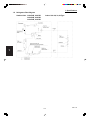
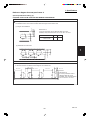
SPLIT SYSTEM AIR CONDITIONER
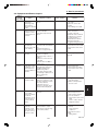
Section
INDOOR MODEL No.
PRODUCT CODE No.
OUTDOOR MODEL No.
PRODUCT CODE No.
XH2672R
854 028 32
CH2672R
854 028 20
XH3672R
854 028 33
CH3072R
854 028 21
XH4272R
854 031 89
CH3672R
854 028 22
TH2672R
854 028 35
CH4272R
854 031 87
TH3672R
854 028 36
C2672R
854 028 24
TH4272R
854 031 90
C3072R
854 028 25
854 028 38
C3672R
854 028 26
THH3672R
854 028 39
C4272R
854 031 88
KH2672R
854 028 28
KH3072R
854 028 29
KH3672R
KHH2672R
854 028 30
854 028 31
UH2672R
854 028 40
UH3672R
854 028 41
THH2672R
1
2
3
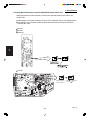
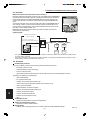
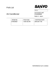
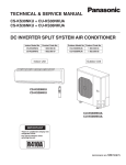
Indoor Unit
Outdoor Unit
4
XH2672R
XH3672R
XH4272R
TH2672R, THH2672R
TH3672R, THH3672R
TH4272R
CH2672R, C2672R
CH3072R, C3072R
CH3672R, C3672R
5
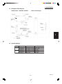
UH2672R
UH3672R
KH3072R
KH3672R
CH4272R, C4272R
85464849248001
KHH2672R
KH2672R
REFERENCE NO. SM831148-1
6
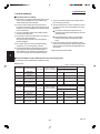
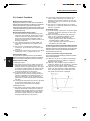
Important
Please Read Before Starting
When
Installing
.............................................................................................
This air conditioning system meets strict safety and operating
standards. As the installer or service person, it is an important
part of your job to install or service the system so it operates
safely and efficiently.
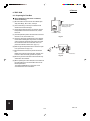
…In a Room
Properly insulate any tubing run inside a room to prevent
“sweating” that can cause dripping and water damage to walls
and floors.
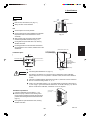
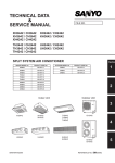
…In Moist or Uneven Locations
Use a raised concrete pad or concrete blocks to provide a
solid, level foundation for the outdoor unit. This prevents water
damage and abnormal vibration.
For safe installation and trouble-free operation, you must :
● Carefully read this instruction booklet before beginning.
● Follow each installation or repair step exactly as shown.
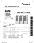
…In an area with High Winds
● Observe all local, state, and national electrical codes.
Securely anchor the outdoor unit down with bolts and a metal
frame. Provide a suitable air baffle.
● Pay close attention to all warning and caution notices
given in this manual.
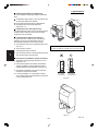
…In a Snowy Area (for Heat Pump-type Sys-tems)
This symbol refers to a hazard or
unsafe practice which can result
in severe personal injury or death.
CAUTION
Install the outdoor unit on a raised platform that is higher than
drifting snow. Provide snow vents.
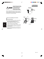
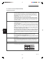
When
Connecting Refrigerant Tubing
.............................................................................................
This symbol refers to a hazard or
unsafe practice which can result
in personal injury or product or
property damage.
If Necessary, Get Help
These instructions are all you need for most installation sites
and maintenance conditions. If you require help for a special
problem, contact our sales/service outlet or your certified
dealer for additional instructions.
In Case of Improper Installation
The manufacturer shall in no way be responsible for improper
installation or maintenance service, including failure to follow
the instructions in this document.
.............................................................................................
ELECTRICAL SHOCK CAN CAUSE SEVERE
PERSONAL INJURY OR DEATH. ONLY A
QUALIFIED, EXPERIENCED ELECTRICIAN
SHOULD ATTEMPT TO WIRE THIS SYSTEM.
●
Highly dangerous electrical voltages are used in this system.
Carefully refer to the wiring diagram and these instructions
when wiring. Improper connections and inadequate
grounding can cause accidentaly injury or death.
●
Ground the unit following local electrical codes.
●
Connect all wiring tightly. Loose wiring may cause overheating at connection points and a possible fire hazard.
●
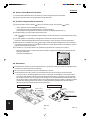
Keep all tubing runs as short as possible.
●
Use the flare method for connecting tubing.
●
Apply refrigerant lubricant to the matching surfaces of the
flare and union tubes before connecting them, then tighten
the nut with a torque wrench for a leak-free connection.
●
Check carefully for leaks before starting the test run.
NOTE
When Wiring
Do not supply power to the unit until all wiring and tubing are
completed or reconnected and checked.
Ventilate the room well, in the event that refrigerant gas
leaks during the installation. Be careful not to allow contact
of the refrigerant gas with a flame as this will cause the
generation of poisonous gas.
Depending on the system type, liquid and gas lines may be
either narrow or wide. Therefore, to avoid confusion the
refrigerant tubing for your particular model is specified as either
“narrow” or “wide” rather than as “liquid” or “gas”.
SPECIAL PRECAUTIONS
●
●
When Servicing
..............................................................................................
●
Turn the power OFF at the main power box (mains) before
opening the unit to check or repair electrical parts and
wiring.
●
Keep your fingers and clothing away from any moving parts.
●
Clean up the site when installation is finished. Check that no
metal scraps or bits of wiring have been left inside the unit.
CAUTION
●
Ventilate any enclosed areas when installing or testing the
refrigeration system. Contact of refrigerant gas with fire or
heat can produce poisonous gas.
●
Confirm after installation that no refrigerant gas is leaking. If
the gas comes in contact with a burning stove, gas water
heater, electric room heater or other heat source, it can
cause the generation of poisonous gas.
When Transporting
...............................................................................................
Be careful when picking up and moving the indoor and outdoor
units. Get a partner to help, and bend your knees when lifting
to reduce strain on your back. Sharp edges or thin aluminum
fins on the air conditioner can cut your fingers.
SM831148
i
Contents
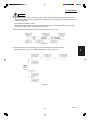
Section 1: SPECIFICATIONS ................................................................................................. I-1
1-1 Unit Specifications .......................................................................................... I-2
1-2 Major Component Specifications .................................................................. I-27
1-3 Other Component Specifications .................................................................. I-47
1-4 Dimensional data .......................................................................................... I-63
1-5 Refrigerant Flow Diagram ............................................................................. I-74
1-6 Operating Range .......................................................................................... I-75
1-7 Heating Capacity .......................................................................................... I-76
1-8 Noise Criterion Curves.................................................................................. I-77
1-9 Increasing the Fan Speed ............................................................................. I-82
1-10 Air throw distance chart ................................................................................ I-83
1-11 Installation Instructions.................................................................................. I-86
1-12 Electrical Wiring ............................................................................................ I-98
1-13 Using Wireless Remote Controller with Wall-mounted Indoor Unit ............. I-102
Section 2: PROCESSES AND FUNCTIONS ........................................................................ II-1
2-1 Room Temperature Control ............................................................................ II-2
2-2 Cold Draft Prevention (Heating Cycle) ........................................................... II-4
2-3 Automatic Fan Speed (Indoor Unit) ................................................................ II-5
2-4 Control Functions ........................................................................................... II-6
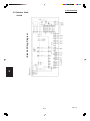
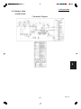
2-5 Outdoor Unit Control PCB .............................................................................. II-9
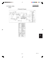
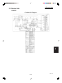
2-6 Outdoor Unit Control PCB (CR-CH4272R) .................................................. II-10
Section 3: ELECTRICAL DATA ............................................................................................ III-1
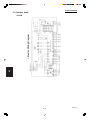
3-1 Indoor Units ................................................................................................... III-2
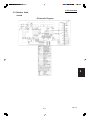
3-2 Outdoor Units .............................................................................................. III-16
Section 4: SERVICE PROCEDURES ...................................................................................IV-1
4-1 Meaning of Alarm Messages .........................................................................IV-2
4-2 Symptoms and Parts to Inspect .....................................................................IV-5
4-3 Details of Alarm Messages ...........................................................................IV-8
4-4 Table of Thermistor Characteristics .............................................................IV-14
Section 5: OUTDOOR UNIT MAINTENANCE REMOTE CONTROL .................................................... V-1
5-1 Overview ....................................................................................................... V-2
5-2 Functions ...................................................................................................... V-2
5-3 Normal Display Operations and Functions ................................................... V-3
5-4 Monitoring Operations: Display of Indoor Unit and Outdoor Unit Sensor
Temperatures ................................................................................................ V-6
5-5 Monitoring the Outdoor Unit Alarm History: Display of Outdoor Unit
Alarm History ................................................................................................ V-7
5-6 Settings Modes: Setting the Outdoor Unit EEPROM ..................................... V-7
Section 6: TEST RUN ..........................................................................................................
6-1 Preparing for Test Run .................................................................................
6-2 Caution ........................................................................................................
6-3 Test Run Procedure .....................................................................................
6-4 Items to Check Before the Test Run .............................................................
6-5 Test Run Using the Remote Controller .........................................................
6-6 Precautions ..................................................................................................
6-7 Table of Self-Diagnostic Functions and Corrections (X, T, U, K Type) ..........
6-8 Examples of Wiring Diagrams ......................................................................
VI-1
VI-2
VI-3
VI-3
VI-4
VI-4
VI-4
VI-5
VI-6
1. Specifications
1. SPECIFICATIONS
1-1
1-2
1-3
1-4
1-5
1-6
1-7
1-8
1-9
1-10
1-11
1-12
1-13
Unit Specifications ......................................................................................................... I-2
Major Component Specifications ............................................................................... I-27
Other Component Specifications ............................................................................... I-47
Dimensional data ......................................................................................................... I-63
Refrigerant Flow Diagram............................................................................................ I-74
Operating Range .......................................................................................................... I-75
Heating Capacity .......................................................................................................... I-76
Noise Criterion Curves ................................................................................................ I-77
Increasing the Fan Speed ........................................................................................... I-82
Air throw distance chart .............................................................................................. I-83
Installation Instructions ............................................................................................... I-86
Electrical Wiring ........................................................................................................... I-98
Using Wireless Remote Controller with Wall-mounted Indoor Unit ........................ I-102
1
2
3
4
5
6
SM831148
I-1
1. Specifications
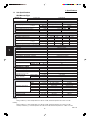
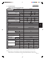
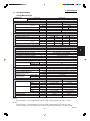
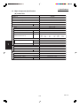
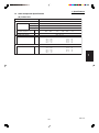
1-1 Unit Specifications
Wall-Mounted Type
MODEL No.
1
2
3
4
5
Indoor Unit
Outdoor Unit
POWER SOURCE
PERFORMANCE
Capacity * [minimum~muximum]
BTU / h
(17˚F)**
BTU / h
Moisture removal (High)
Pints / h
Air circulation (H / M / L) 230 V
CFM
External Static Pressure
in. Aq
S.E.E.R. / H.S.P.F. (Region 4)
BTU / Wh
ELECTRICAL RATINGS
Voltage rating
V
Available voltage range
V
Max. Running amperes* (Without Back-up Heater)
A
Power input
W
(17˚F)**
W
Back-up Heater
kW
Maximum overcurrent protection (Indoor/Outdoor)
A
FEATURES
Controls
Low ambient control
Fan speeds Indoor / Outdoor
Optional Wired Remote Controller
Optional Wireless Remote Controller
Air deflection (Horizontal / Vertical )
Air filter
Drain pump (Drain connection)
Compressor
Indoor - Hi/Me/Lo
dB - A
Operation sound
Outdoor - Hi
dB - A
Refrigerant control
REFRIGERANT TUBING
Limit of tubing length
ft. (m)
Limit of tubing length at shipment
ft. (m)
Limit of elevation difference
ft. (m)
between the two units
ft. (m)
Refrigerant tube
Narrow tube
in. (mm)
outer diameter
Wide tube
in. (mm)
Refrigerant amount at shipment
lbs. (kg)
DIMENSIONS & WEIGHT
Unit dimensions
Height
in. (mm)
Width
in. (mm)
Depth
in. (mm)
Package dimensions
Height
in. (mm)
Width
in. (mm)
Depth
in. (mm)
Net weight
lbs. (kg)
Shipping weight
lbs. (kg)
Shipping volume
cu.ft. (m 3 )
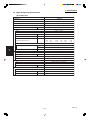
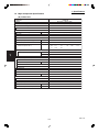
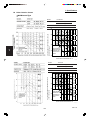
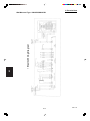
KHH2672R
CH2672R
230 - 208 V / 1 Phase / 60 Hz
Cooling
Heating
23,000 [9,500~23,000]
27,600 [8,000~27,600]
18,500
7.4
540 / 460 / 380
15.9
10.3
230
208
VAC 187 - 253
14.0
15.5
2,610
2,610
230
208
VAC 187 - 253
14.6
16.1
2,720
2,720
2,160
2,160
1.8
1.47
15 / 30
Microprocessor
Built-in 0˚F
3 and Automatic control / Variable
RCS-SH80UG / RCS-TM80BG
RCS-SH1UA / RCS-BH80UA. WL
/ Automatic (Vertical )
Washable
(20A , OD26mm)
Rotary(SANYO)
45 / 42 / 40
49
Electronic Expansion Valve (MOV)
165 (50)
10~100 (3~30)
Outdoor unit is higher than indoor unit : 100 (30)
Outdoor unit is lower than indoor unit : 50 (15)
3 / 8 (6.35)
5 / 8 (15.88)
4.19 (1.9) - R410A
Indoor unit
Outdoor unit
14- 9/16 (370)
30- 23/32 (780)
49- 7/32 (1,250)
37 (940)
8- 9/32 (210)
13- 3/8 (340)
Indoor unit
Outdoor unit
18- 7/16 (468)
34- 31/32 (888)
52- 23/32 (1,339)
39- 31/32 (1,015)
11- 3/8 (289)
16- 3/32 (409)
44.1 (20)
128 (58)
59.5 (27)
148 (67)
6.4 (0.181)
13.0 (0.369)
DATA SUBJECT TO CHANGE WITHOUT NOTICE.
Cooling:
Rating conditions (*) : Room temperature 80 °F DB / 67 °F WB, Ambient temperature 95 °F DB / 75 °F WB
6
Heating:
Rating conditions (*) : Room temperature 70 °F DB / 60 °F WB, Ambient temperature 47 °F DB / 43 °F WB
Low temp conditions (**) : Room temperature 70 °F DB / 60 °F WB, Ambient temperature 17 °F DB / 15 °F WB
SM831148
I-2
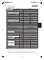
1. Specifications
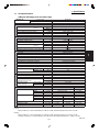
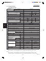
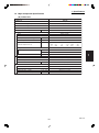
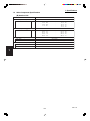
1-1 Unit Specifications
Wall-Mounted Type
MODEL No.
Indoor Unit
Outdoor Unit
POWER SOURCE
PERFORMANCE
Capacity * [minimum~muximum]
BTU / h
(17˚F)**
BTU / h
Moisture removal (High)
Pints / h
Air circulation (H / M / L) 230 V
CFM
External Static Pressure
in. Aq
S.E.E.R. / H.S.P.F. (Region 4)
BTU / Wh
ELECTRICAL RATINGS
Voltage rating
V
Available voltage range
V
Max. Running amperes*
A
Power input
W
(17˚F)**
W
Back-up Heater
kW
Maximum overcurrent protection (Indoor/Outdoor)
A
FEATURES
Controls
Low ambient control
Fan speeds Indoor / Outdoor
Optional Wired Remote Controller
Optional Wireless Remote Controller
Air deflection (Horizontal / Vertical )
Air filter
Drain pump (Drain connection)
Compressor
Indoor - Hi/Me/Lo
dB - A
Operation sound
Outdoor - Hi
dB - A
Refrigerant control
REFRIGERANT TUBING
Limit of tubing length
ft. (m)
Limit of tubing length at shipment
ft. (m)
Limit of elevation difference
ft. (m)
between the two units
ft. (m)
Refrigerant tube
Narrow tube
in. (mm)
outer diameter
Wide tube
in. (mm)
Refrigerant amount at shipment
lbs. (kg)
DIMENSIONS & WEIGHT
Unit dimensions
Height
in. (mm)
Width
in. (mm)
Depth
in. (mm)
Package dimensions
Height
in. (mm)
Width
in. (mm)
Depth
in. (mm)
Net weight
lbs. (kg)
Shipping weight
lbs. (kg)
Shipping volume
cu.ft. (m 3 )
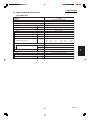
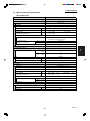
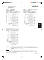
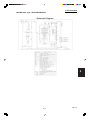
KH2672R
CH2672R
230 - 208 V / 1 Phase / 60 Hz
Cooling
Heating
25,200 [9,500~25,200]
29,200 [8,000~29,200]
17,200
8.1
559 / 475 / 390
14.9
10.2
230
208
VAC 187 - 253
15.3
16.9
2,840
2,840
230
208
VAC 187 - 253
14.0
15.5
2,620
2,620
2,030
2,030
15 / 30
Microprocessor
Built-in 0˚F
3 and Automatic control / Variable
RCS-SH80UG / RCS-TM80BG
RCS-SH1UA / RCS-BH80UA. WL
/ Automatic (Vertical )
Washable
(20A , OD26mm)
Rotary(SANYO)
48 / 42 / 38
49
Electronic Expansion Valve (MOV)
1
2
165 (50)
10~100 (3~30)
Outdoor unit is higher than indoor unit : 100 (30)
Outdoor unit is lower than indoor unit : 50 (15)
3 / 8 (6.35)
5 / 8 (15.88)
4.19 (1.9) - R410A
Indoor unit
Outdoor unit
12- 63/64 (330)
30- 23/32 (780)
44- 7/8 (1,140)
37 (940)
8- 31/32 (228)
13- 3/8 (340)
Indoor unit
Outdoor unit
15- 11/32 (390)
34- 31/32 (888)
47- 27/32 (1,215)
39- 31/32 (1,015)
11- 17/32 (293)
16- 3/32 (409)
40 (18)
128 (58)
44 (20)
148 (67)
4.9 (0.139)
13.0 (0.369)
DATA SUBJECT TO CHANGE WITHOUT NOTICE.
3
4
5
Cooling:
Rating conditions (*) : Room temperature 80 °F DB / 67 °F WB, Ambient temperature 95 °F DB / 75 °F WB
Heating:
Rating conditions (*) : Room temperature 70 °F DB / 60 °F WB, Ambient temperature 47 °F DB / 43 °F WB
Low temp conditions (**) : Room temperature 70 °F DB / 60 °F WB, Ambient temperature 17 °F DB / 15 °F WB
SM831148
I-3
6
1. Specifications
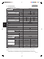
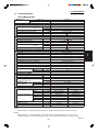
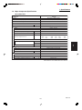
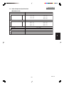
1-1 Unit Specifications
Wall-Mounted Type
MODEL No.
1
2
3
4
5
Indoor Unit
Outdoor Unit
POWER SOURCE
PERFORMANCE
Capacity * [minimum~muximum]
BTU / h
(17˚F)**
BTU / h
Moisture removal (High)
Pints / h
Air circulation (H / M / L) 230 V
CFM
External Static Pressure
in. Aq
S.E.E.R. / H.S.P.F. (Region 4)
BTU / Wh
ELECTRICAL RATINGS
Voltage rating
V
Available voltage range
V
Max. Running amperes*
A
Power input
W
(17˚F)**
W
Back-up Heater
kW
Maximum overcurrent protection (Indoor/Outdoor)
A
FEATURES
Controls
Low ambient control
Fan speeds Indoor / Outdoor
Optional Wired Remote Controller
Optional Wireless Remote Controller
Air deflection (Horizontal / Vertical )
Air filter
Drain pump (Drain connection)
Compressor
Indoor - Hi/Me/Lo
dB - A
Operation sound
Outdoor - Hi
dB - A
Refrigerant control
REFRIGERANT TUBING
Limit of tubing length
ft. (m)
Limit of tubing length at shipment
ft. (m)
Limit of elevation difference
ft. (m)
between the two units
ft. (m)
Refrigerant tube
Narrow tube
in. (mm)
outer diameter
Wide tube
in. (mm)
Refrigerant amount at shipment
lbs. (kg)
DIMENSIONS & WEIGHT
Unit dimensions
Height
in. (mm)
Width
in. (mm)
Depth
in. (mm)
Package dimensions
Height
in. (mm)
Width
in. (mm)
Depth
in. (mm)
Net weight
lbs. (kg)
Shipping weight
lbs. (kg)
Shipping volume
cu.ft. (m 3 )
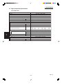
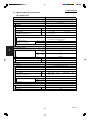
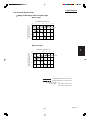
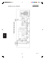
KH3072R
CH3072R
230 - 208 V / 1 Phase / 60 Hz
Cooling
Heating
29,800 [9,500~29,800]
34,800 [8,000~34,800]
20,000
9.7
840 / 740 / 620
15.0
9.0
230
208
VAC 187 - 253
17.7
19.6
3,690
3,690
230
208
VAC 187 - 253
16.2
17.9
3,390
3,390
2,460
2,460
15 / 35
Microprocessor
Built-in 0˚F
3 and Automatic control / Variable
RCS-SH80UG / RCS-TM80BG
RCS-SH1UA / RCS-BH80UA. WL
/ Automatic (Vertical )
Washable
(20A , OD26mm)
Rotary(SANYO)
46 / 42 / 38
52
Electronic Expansion Valve (MOV)
165 (50)
10~100 (3~30)
Outdoor unit is higher than indoor unit : 100 (30)
Outdoor unit is lower than indoor unit : 50 (15)
3 / 8 (6.35)
5 / 8 (15.88)
5.73 (2.6) - R410A
Indoor unit
Outdoor unit
14- 9/16 (370)
30- 23/32 (780)
59- 1/16 (1,500)
37 (940)
9- 7/16 (240)
13- 3/8 (340)
Indoor unit
Outdoor unit
18- 7/16 (468)
34- 31/32 (888)
62- 9/16 (1,589)
39- 31/32 (1,015)
12- 9/16 (319)
16- 3/32 (409)
63.9 (29)
143 (65)
81.6 (37)
161 (73)
8.4 (0.237)
13.0 (0.369)
DATA SUBJECT TO CHANGE WITHOUT NOTICE.
Cooling:
Rating conditions (*) : Room temperature 80 °F DB / 67 °F WB, Ambient temperature 95 °F DB / 75 °F WB
6
Heating:
Rating conditions (*) : Room temperature 70 °F DB / 60 °F WB, Ambient temperature 47 °F DB / 43 °F WB
Low temp conditions (**) : Room temperature 70 °F DB / 60 °F WB, Ambient temperature 17 °F DB / 15 °F WB
SM831148
I-4
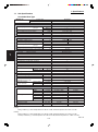
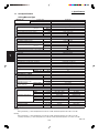
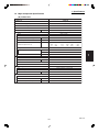
1. Specifications
1-1 Unit Specifications
Wall-Mounted Type
MODEL No.
Indoor Unit
Outdoor Unit
POWER SOURCE
PERFORMANCE
Capacity * [minimum~muximum]
BTU / h
(17˚F)**
BTU / h
Moisture removal (High)
Pints / h
Air circulation (H / M / L) 230 V
CFM
External Static Pressure
in. Aq
S.E.E.R. / H.S.P.F. (Region 4)
BTU / Wh
ELECTRICAL RATINGS
Voltage rating
V
Available voltage range
V
Max. Running amperes*
A
Power input
W
(17˚F)**
W
Back-up Heater
kW
Maximum overcurrent protection (Indoor/Outdoor)
A
FEATURES
Controls
Low ambient control
Fan speeds Indoor / Outdoor
Optional Wired Remote Controller
Optional Wireless Remote Controller
Air deflection (Horizontal / Vertical )
Air filter
Drain pump (Drain connection)
Compressor
Indoor - Hi/Me/Lo
dB - A
Operation sound
Outdoor - Hi
dB - A
Refrigerant control
REFRIGERANT TUBING
Limit of tubing length
ft. (m)
Limit of tubing length at shipment
ft. (m)
Limit of elevation difference
ft. (m)
between the two units
ft. (m)
Refrigerant tube
Narrow tube
in. (mm)
outer diameter
Wide tube
in. (mm)
Refrigerant amount at shipment
lbs. (kg)
DIMENSIONS & WEIGHT
Unit dimensions
Height
in. (mm)
Width
in. (mm)
Depth
in. (mm)
Package dimensions
Height
in. (mm)
Width
in. (mm)
Depth
in. (mm)
Net weight
lbs. (kg)
Shipping weight
lbs. (kg)
Shipping volume
cu.ft. (m 3 )
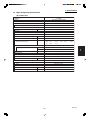
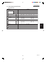
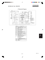
KH3672R
CH3672R
230 - 208 V / 1 Phase / 60 Hz
Cooling
Heating
31,400 [9,500~31,400]
36,400 [8,000~36,400]
20,200
10.0
830 / 710 / 590
15.9
9.0
230
208
VAC 187 - 253
17.9
19.8
3,750
3,750
230
208
VAC 187 - 253
15.9
17.6
3,320
3,320
2,450
2,450
15 / 35
Microprocessor
Built-in 0˚F
3 and Automatic control / Variable
RCS-SH80UG / RCS-TM80BG
RCS-SH1UA / RCS-BH80UA. WL
/ Automatic (Vertical )
Washable
(20A , OD26mm)
Rotary(SANYO)
48 / 44 / 40
52
Electronic Expansion Valve (MOV)
1
2
165 (50)
10~100 (3~30)
Outdoor unit is higher than indoor unit : 100 (30)
Outdoor unit is lower than indoor unit : 50 (15)
3 / 8 (6.35)
5 / 8 (15.88)
6.17 (2.8) - R410A
Indoor unit
Outdoor unit
14- 9/16 (370)
30- 23/32 (780)
59- 1/16 (1,500)
37 (940)
9- 7/16 (240)
13- 3/8 (340)
Indoor unit
Outdoor unit
18- 7/16 (468)
34- 31/32 (888)
62- 9/16 (1,589)
39- 31/32 (1,015)
12- 9/16 (319)
16- 3/32 (409)
72.8 (33)
143 (65)
90.4 (41)
161 (73)
8.4 (0.237)
13.0 (0.369)
DATA SUBJECT TO CHANGE WITHOUT NOTICE.
3
4
5
Cooling:
Rating conditions (*) : Room temperature 80 °F DB / 67 °F WB, Ambient temperature 95 °F DB / 75 °F WB
Heating:
Rating conditions (*) : Room temperature 70 °F DB / 60 °F WB, Ambient temperature 47 °F DB / 43 °F WB
Low temp conditions (**) : Room temperature 70 °F DB / 60 °F WB, Ambient temperature 17 °F DB / 15 °F WB
SM831148
I-5
6
1. Specifications
1-1 Unit Specifications
Wall-Mounted Type
MODEL No.
1
2
3
4
5
Indoor Unit
Outdoor Unit
POWER SOURCE
PERFORMANCE
Capacity * [minimum~muximum]
BTU / h
(17˚F)**
BTU / h
Moisture removal (High)
Pints / h
Air circulation (H / M / L) 230 V
CFM
External Static Pressure
in. Aq
S.E.E.R. / H.S.P.F. (Region 4)
BTU / Wh
ELECTRICAL RATINGS
Voltage rating
V
Available voltage range
V
Max. Running amperes*
A
Power input
W
(17˚F)**
W
Back-up Heater
kW
Maximum overcurrent protection (Indoor/Outdoor)
A
FEATURES
Controls
Low ambient control
Fan speeds Indoor / Outdoor
Optional Wired Remote Controller
Optional Wireless Remote Controller
Air deflection (Horizontal / Vertical )
Air filter
Drain pump (Drain connection)
Compressor
Indoor - Hi/Me/Lo
dB - A
Operation sound
Outdoor - Hi
dB - A
Refrigerant control
REFRIGERANT TUBING
Limit of tubing length
ft. (m)
Limit of tubing length at shipment
ft. (m)
Limit of elevation difference
ft. (m)
between the two units
ft. (m)
Refrigerant tube
Narrow tube
in. (mm)
outer diameter
Wide tube
in. (mm)
Refrigerant amount at shipment
lbs. (kg)
DIMENSIONS & WEIGHT
Unit dimensions
Height
in. (mm)
Width
in. (mm)
Depth
in. (mm)
Package dimensions
Height
in. (mm)
Width
in. (mm)
Depth
in. (mm)
Net weight
lbs. (kg)
Shipping weight
lbs. (kg)
Shipping volume
cu.ft. (m 3 )
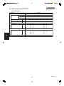
KH2672R
C2672R
230 - 208 V / 1 Phase / 60 Hz
Cooling
25,200 [9,500~25,200]
8.1
559 / 475 / 390
14.9
230
208
VAC 187 - 253
15.3
2,840
16.9
2,840
15 / 30
Microprocessor
Built-in 0˚F
3 and Automatic control / Variable
RCS-SH80UG / RCS-TM80BG
RCS-SH1UA / RCS-BH80UA. WL
/ Automatic (Vertical )
Washable
(20A , OD26mm)
Rotary(SANYO)
48 / 42 / 38
49
Electronic Expansion Valve (MOV)
165 (50)
10~100 (3~30)
Outdoor unit is higher than indoor unit : 100 (30)
Outdoor unit is lower than indoor unit : 50 (15)
3 / 8 (6.35)
5 / 8 (15.88)
4.19 (1.9) - R410A
Indoor unit
Outdoor unit
12- 63/64 (330)
30- 23/32 (780)
44- 7/8 (1,140)
37 (940)
8- 31/32 (228)
13- 3/8 (340)
Indoor unit
Outdoor unit
15- 11/32 (390)
34- 31/32 (888)
47- 27/32 (1,215)
39- 31/32 (1,015)
11- 17/32 (293)
16- 3/32 (409)
40 (18)
128 (58)
44 (20)
148 (67)
4.9 (0.139)
13.0 (0.369)
DATA SUBJECT TO CHANGE WITHOUT NOTICE.
Cooling:
Rating conditions (*) : Room temperature 80 °F DB / 67 °F WB, Ambient temperature 95 °F DB / 75 °F WB
6
Heating:
Rating conditions (*) : Room temperature 70 °F DB / 60 °F WB, Ambient temperature 47 °F DB / 43 °F WB
Low temp conditions (**) : Room temperature 70 °F DB / 60 °F WB, Ambient temperature 17 °F DB / 15 °F WB
SM831148
I-6
1. Specifications
1-1 Unit Specifications
Wall-Mounted Type
MODEL No.
Indoor Unit
Outdoor Unit
POWER SOURCE
PERFORMANCE
Capacity * [minimum~muximum]
BTU / h
(17˚F)**
BTU / h
Moisture removal (High)
Pints / h
Air circulation (H / M / L) 230 V
CFM
External Static Pressure
in. Aq
S.E.E.R.
BTU / Wh
ELECTRICAL RATINGS
Voltage rating
V
Available voltage range
V
Max. Running amperes*
A
Power input
W
(17˚F)**
W
Back-up Heater
kW
Maximum overcurrent protection (Indoor/Outdoor)
A
FEATURES
Controls
Low ambient control
Fan speeds Indoor / Outdoor
Optional Wired Remote Controller
Optional Wireless Remote Controller
Air deflection (Horizontal / Vertical )
Air filter
Drain pump (Drain connection)
Compressor
Indoor - Hi/Me/Lo
dB - A
Operation sound
Outdoor - Hi
dB - A
Refrigerant control
REFRIGERANT TUBING
Limit of tubing length
ft. (m)
Limit of tubing length at shipment
ft. (m)
Limit of elevation difference
ft. (m)
between the two units
ft. (m)
Refrigerant tube
Narrow tube
in. (mm)
outer diameter
Wide tube
in. (mm)
Refrigerant amount at shipment
lbs. (kg)
DIMENSIONS & WEIGHT
Unit dimensions
Height
in. (mm)
Width
in. (mm)
Depth
in. (mm)
Package dimensions
Height
in. (mm)
Width
in. (mm)
Depth
in. (mm)
Net weight
lbs. (kg)
Shipping weight
lbs. (kg)
Shipping volume
cu.ft. (m 3 )
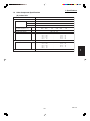
KH3072R
C3072R
230 - 208 V / 1 Phase / 60 Hz
Cooling
29,800 [9,500~29,800]
9.7
840 / 740 / 620
15.0
230
208
VAC 187 - 253
17.7
3,690
19.6
3,690
15 / 35
Microprocessor
Built-in 0˚F
3 and Automatic control / Variable
RCS-SH80UG / RCS-TM80BG
RCS-SH1UA / RCS-BH80UA. WL
/ Automatic (Vertical )
Washable
(20A , OD26mm)
Rotary(SANYO)
46 / 42 / 38
52
Electronic Expansion Valve (MOV)
1
2
165 (50)
10~100 (3~30)
Outdoor unit is higher than indoor unit : 100 (30)
Outdoor unit is lower than indoor unit : 50 (15)
3 / 8 (6.35)
5 / 8 (15.88)
5.73 (2.6) - R410A
Indoor unit
Outdoor unit
14- 9/16 (370)
30- 23/32 (780)
59- 1/16 (1,500)
37 (940)
9- 7/16 (240)
13- 3/8 (340)
Indoor unit
Outdoor unit
18- 7/16 (468)
34- 31/32 (888)
62- 9/16 (1,589)
39- 31/32 (1,015)
12- 9/16 (319)
16- 3/32 (409)
63.9 (29)
143 (65)
81.6 (37)
161 (73)
8.4 (0.237)
13.0 (0.369)
DATA SUBJECT TO CHANGE WITHOUT NOTICE.
3
4
5
Cooling:
Rating conditions (*) : Room temperature 80 °F DB / 67 °F WB, Ambient temperature 95 °F DB / 75 °F WB
Heating:
Rating conditions (*) : Room temperature 70 °F DB / 60 °F WB, Ambient temperature 47 °F DB / 43 °F WB
Low temp conditions (**) : Room temperature 70 °F DB / 60 °F WB, Ambient temperature 17 °F DB / 15 °F WB
SM831148
I-7
6
1. Specifications
1-1 Unit Specifications
Wall-Mounted Type
MODEL No.
1
2
3
4
5
Indoor Unit
Outdoor Unit
POWER SOURCE
PERFORMANCE
Capacity * [minimum~muximum]
BTU / h
(17˚F)**
BTU / h
Moisture removal (High)
Pints / h
Air circulation (H / M / L) 230 V
CFM
External Static Pressure
in. Aq
S.E.E.R.
BTU / Wh
ELECTRICAL RATINGS
Voltage rating
V
Available voltage range
V
Max. Running amperes*
A
Power input
W
(17˚F)**
W
Back-up Heater
kW
Maximum overcurrent protection (Indoor/Outdoor)
A
FEATURES
Controls
Low ambient control
Fan speeds Indoor / Outdoor
Optional Wired Remote Controller
Optional Wireless Remote Controller
Air deflection (Horizontal / Vertical )
Air filter
Drain pump (Drain connection)
Compressor
Indoor - Hi/Me/Lo
dB - A
Operation sound
Outdoor - Hi
dB - A
Refrigerant control
REFRIGERANT TUBING
Limit of tubing length
ft. (m)
Limit of tubing length at shipment
ft. (m)
Limit of elevation difference
ft. (m)
between the two units
ft. (m)
Refrigerant tube
Narrow tube
in. (mm)
outer diameter
Wide tube
in. (mm)
Refrigerant amount at shipment
lbs. (kg)
DIMENSIONS & WEIGHT
Unit dimensions
Height
in. (mm)
Width
in. (mm)
Depth
in. (mm)
Package dimensions
Height
in. (mm)
Width
in. (mm)
Depth
in. (mm)
Net weight
lbs. (kg)
Shipping weight
lbs. (kg)
Shipping volume
cu.ft. (m 3 )
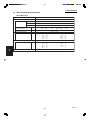
KH3672R
C3672R
230 - 208 V / 1 Phase / 60 Hz
Cooling
31,400 [9,500~31,400]
10.0
830 / 710 / 590
15.9
230
208
VAC 187 - 253
17.9
3,750
19.8
3,750
15 / 35
Microprocessor
Built-in 0˚F
3 and Automatic control / Variable
RCS-SH80UG / RCS-TM80BG
RCS-SH1UA / RCS-BH80UA. WL
/ Automatic (Vertical )
Washable
(20A , OD26mm)
Rotary(SANYO)
48 / 44 / 40
52
Electronic Expansion Valve (MOV)
165 (50)
10~100 (3~30)
Outdoor unit is higher than indoor unit : 100 (30)
Outdoor unit is lower than indoor unit : 50 (15)
3 / 8 (6.35)
5 / 8 (15.88)
6.17 (2.8) - R410A
Indoor unit
Outdoor unit
14- 9/16 (370)
30- 23/32 (780)
59- 1/16 (1,500)
37 (940)
9- 7/16 (240)
13- 3/8 (340)
Indoor unit
Outdoor unit
18- 7/16 (468)
34- 31/32 (888)
62- 9/16 (1,589)
39- 31/32 (1,015)
12- 9/16 (319)
16- 3/32 (409)
72.8 (33)
143 (65)
90.4 (41)
161 (73)
8.4 (0.237)
13.0 (0.369)
DATA SUBJECT TO CHANGE WITHOUT NOTICE.
Cooling:
Rating conditions (*) : Room temperature 80 °F DB / 67 °F WB, Ambient temperature 95 °F DB / 75 °F WB
6
Heating:
Rating conditions (*) : Room temperature 70 °F DB / 60 °F WB, Ambient temperature 47 °F DB / 43 °F WB
Low temp conditions (**) : Room temperature 70 °F DB / 60 °F WB, Ambient temperature 17 °F DB / 15 °F WB
SM831148
I-8
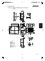
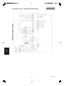
1. Specifications
1-1 Unit Specifications
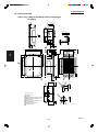
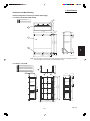
4-Way Air Discharge Semi-Concealed Type
MODEL No.
Indoor Unit
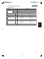
XH2672R
Outdoor Unit
CH2672R
230 - 208 V / 1 Phase / 60 Hz
POWER SOURCE
Cooling
Heating
PERFORMANCE
Capacity * [minimum~muximum]
BTU / h 24,800 [9,500~24,800]
29,800 [8,000~29,800]
(17˚F)**
BTU / h
18,300
Moisture removal (High)
Pints / h
8.1
Air circulation (H / M / L) 230 V
CFM
710 / 530 / 450
External Static Pressure
in. Aq
S.E.E.R. / H.S.P.F. (Region 4)
BTU / Wh
14.1
10.5
ELECTRICAL RATINGS
Voltage rating
V
230
208
230
208
Available voltage range
V
VAC 187 - 253
VAC 187 - 253
Max. Running amperes*
A
15.6
17.3
14.8
16.4
Power input
W
2,920
2,920
2,790
2,790
(17˚F)**
W
2,200
2,200
Back-up Heater
kW
Maximum overcurrent protection (Indoor/Outdoor)
A
15 / 30
FEATURES
Controls
Microprocessor
Low ambient control
Built-in 0˚F
Fan speeds Indoor / Outdoor
3 and Automatic control / Variable
RCS-SH80UG / RCS-TM80BG
Optional Wired Remote Controller
Optional Wireless Remote Controller
RCS-SH80UA.WL / RCS-BH80UA. WL
/ Automatic (Vertical )
Air deflection (Horizontal / Vertical )
Air filter
Washable, long life (2,500 hr)
Max.head 2-33/64 in. above drain connection (25A , OD32mm)
Drain pump (Drain connection)
Compressor
Rotary(SANYO)
Indoor - Hi/Me/Lo
dB - A
38 / 35 / 31
Operation sound
Outdoor - Hi
dB - A
49
Refrigerant control
Electronic Expansion Valve (MOV)
REFRIGERANT TUBING
Limit of tubing length
ft. (m)
165 (50)
Limit of tubing length at shipment
ft. (m)
10~100 (3~30)
Limit of elevation difference
ft. (m)
Outdoor unit is higher than indoor unit : 100 (30)
between the two units
ft. (m)
Outdoor unit is lower than indoor unit : 50 (15)
Refrigerant tube
Narrow tube
in. (mm)
3 / 8 (6.35)
outer diameter
Wide tube
in. (mm)
5 / 8 (15.88)
Refrigerant amount at shipment
lbs. (kg)
4.19 (1.9) - R410A
Indoor unit (Include panel)
Outdoor unit
DIMENSIONS & WEIGHT
Unit dimensions
Height
in. (mm)
13-5/16 (338)
30- 23/32 (780)
Width
in. (mm)
33-55/64 (860)
37 (940)
Depth
in. (mm)
33-55/64 (860)
13- 3/8 (340)
Package dimensions
Body
Panel
Outdoor unit
Height
in. (mm) 11-9/64 (283)
4-3/32 (104)
34- 31/32 (888)
Width
in. (mm)
32-7/8 (835)
37-61/64 (964) 39- 31/32 (1,015)
Depth
in. (mm) 33-9/32 (845)
39-21/64 (999)
16- 3/32 (409)
Net weight
lbs. (kg)
49 (22)
11 (5)
128 (58)
Shipping weight
lbs. (kg)
57 (26)
18 (8)
148 (67)
Shipping volume
cu.ft. (m 3 )
7.1 (0.200)
3.6 (0.100)
13.0 (0.369)
DATA SUBJECT TO CHANGE WITHOUT NOTICE.
1
2
3
4
5
Cooling:
Rating conditions (*) : Room temperature 80 °F DB / 67 °F WB, Ambient temperature 95 °F DB / 75 °F WB
Heating:
Rating conditions (*) : Room temperature 70 °F DB / 60 °F WB, Ambient temperature 47 °F DB / 43 °F WB
Low temp conditions (**) : Room temperature 70 °F DB / 60 °F WB, Ambient temperature 17 °F DB / 15 °F WB
SM831148
I-9
6
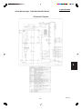
1. Specifications
1-1 Unit Specifications
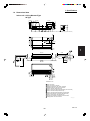
4-Way Air Discharge Semi-Concealed Type
MODEL No.
1
2
3
4
5
Indoor Unit
XH3672R
Outdoor Unit
CH3672R
230 - 208 V / 1 Phase / 60 Hz
POWER SOURCE
Cooling
Heating
PERFORMANCE
Capacity * [minimum~muximum]
BTU / h 32,600 [9,500~32,600]
37,600 [8,000~37,600]
(17˚F)**
BTU / h
20,000
Moisture removal (High)
Pints / h
10.6
Air circulation (H / M / L) 230 V
CFM
1050 / 840 / 720
External Static Pressure
in. Aq
S.E.E.R. / H.S.P.F. (Region 4)
BTU / Wh
14.6
9.1
ELECTRICAL RATINGS
Voltage rating
V
230
208
230
208
Available voltage range
V
VAC 187 - 253
VAC 187 - 253
Max. Running amperes*
A
18.7
20.7
15.9
17.6
Power input
W
3,950
3,950
3,350
3,350
(17˚F)**
W
2,450
2,450
Back-up Heater
kW
Maximum overcurrent protection (Indoor/Outdoor)
A
15 / 35
FEATURES
Controls
Microprocessor
Low ambient control
Built-in 0˚F
Fan speeds Indoor / Outdoor
3 and Automatic control / Variable
RCS-SH80UG / RCS-TM80BG
Optional Wired Remote Controller
Optional Wireless Remote Controller
RCS-SH80UA. WL / RCS-BH80UA. WL
/ Automatic (Vertical )
Air deflection (Horizontal / Vertical )
Air filter
Washable, long life (2,500 hr)
Max.head 2-33/64 in. above drain connection (25A , OD32mm)
Drain pump (Drain connection)
Compressor
Rotary(SANYO)
Indoor - Hi/Me/Lo
dB - A
44 / 37 / 33
Operation sound
Outdoor - Hi
dB - A
52
Refrigerant control
Electronic Expansion Valve (MOV)
REFRIGERANT TUBING
Limit of tubing length
ft. (m)
165 (50)
Limit of tubing length at shipment
ft. (m)
10~100 (3~30)
Limit of elevation difference
ft. (m)
Outdoor unit is higher than indoor unit : 100 (30)
between the two units
ft. (m)
Outdoor unit is lower than indoor unit : 50 (15)
Refrigerant tube
Narrow tube
in. (mm)
3 / 8 (6.35)
outer diameter
Wide tube
in. (mm)
5 / 8 (15.88)
Refrigerant amount at shipment
lbs. (kg)
6.17 (2.8) - R410A
Indoor unit (Include panel)
Outdoor unit
DIMENSIONS & WEIGHT
Unit dimensions
Height
in. (mm)
14-31/64 (368)
30- 23/32 (780)
Width
in. (mm)
45-9/32 (1,150)
37 (940)
Depth
in. (mm)
33-55/64 (860)
13- 3/8 (340)
Package dimensions
Body
Panel
Outdoor unit
Height
in. (mm) 12-13/32 (315)
4-3/32 (104)
34- 31/32 (888)
Width
in. (mm) 44-19/64 (1,125) 49-31/64 (1,257) 39- 31/32 (1,015)
Depth
in. (mm) 33-9/32 (845)
39-21/64 (999)
16- 3/32 (409)
Net weight
lbs. (kg)
60 (27)
16 (7)
143 (65)
Shipping weight
lbs. (kg)
71 (32)
22 (10)
161 (73)
Shipping volume
cu.ft. (m 3 )
10.6 (0.299)
4.6 (0.131)
13.0 (0.369)
DATA SUBJECT TO CHANGE WITHOUT NOTICE.
Cooling:
Rating conditions (*) : Room temperature 80 °F DB / 67 °F WB, Ambient temperature 95 °F DB / 75 °F WB
6
Heating:
Rating conditions (*) : Room temperature 70 °F DB / 60 °F WB, Ambient temperature 47 °F DB / 43 °F WB
Low temp conditions (**) : Room temperature 70 °F DB / 60 °F WB, Ambient temperature 17 °F DB / 15 °F WB
SM831148
I-10
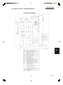
1. Specifications
1-1 Unit Specifications
4-Way Air Discharge Semi-Concealed Type
MODEL No.
Indoor Unit
XH4272R
Outdoor Unit
CH4272R
230 - 208 V / 1 Phase / 60 Hz
POWER SOURCE
Cooling
Heating
PERFORMANCE
Capacity * [minimum~muximum]
BTU / h 39,500 [9,500~39,500]
48,000 [8,000~48,000]
(17˚F)**
BTU / h
31,800
Moisture removal (High)
Pints / h
12.6
Air circulation (H / M / L) 230 V
CFM
1050 / 840 / 720
External Static Pressure
in. Aq
S.E.E.R. / H.S.P.F. (Region 4)
BTU / Wh
14.6
10.4
ELECTRICAL RATINGS
Voltage rating
V
230
208
230
208
Available voltage range
V
VAC 187 - 253
VAC 187 - 253
Max. Running amperes*
A
23.0
25.4
22.4
24.8
Power input
W
4,520
4,520
4,360
4,360
(17˚F)**
W
3,540
3,540
Back-up Heater
kW
Maximum overcurrent protection (Indoor/Outdoor)
A
15 / 40
FEATURES
Controls
Microprocessor
Low ambient control
Built-in 0˚F
Fan speeds Indoor / Outdoor
3 and Automatic control / Variable
RCS-SH80UG / RCS-TM80BG
Optional Wired Remote Controller
Optional Wireless Remote Controller
RCS-SH80UA. WL / RCS-BH80UA. WL
/ Automatic (Vertical )
Air deflection (Horizontal / Vertical )
Air filter
Washable, long life (2,500 hr)
Max.head 2-33/64 in. above drain connection (25A , OD32mm)
Drain pump (Drain connection)
Compressor
Rotary(SANYO)
Indoor - Hi/Me/Lo
dB - A
45 / 38 / 34
Operation sound
Outdoor - Hi
dB - A
53
Refrigerant control
Electronic Expansion Valve (MOV)
REFRIGERANT TUBING
Limit of tubing length
ft. (m)
165 (50)
Limit of tubing length at shipment
ft. (m)
10~100 (3~30)
Limit of elevation difference
ft. (m)
Outdoor unit is higher than indoor unit : 100 (30)
between the two units
ft. (m)
Outdoor unit is lower than indoor unit : 50 (15)
Refrigerant tube
Narrow tube
in. (mm)
3 / 8 (6.35)
outer diameter
Wide tube
in. (mm)
5 / 8 (15.88)
Refrigerant amount at shipment
lbs. (kg)
7.94 (3.6) - R410A
Indoor unit (Include panel)
Outdoor unit
DIMENSIONS & WEIGHT
Unit dimensions
Height
in. (mm)
14-31/64 (368)
48-7/16 (1,230 )
Width
in. (mm)
45-9/32 (1,150)
37 (940)
Depth
in. (mm)
33-55/64 (860)
13- 3/8 (340)
Package dimensions
Body
Panel
Outdoor unit
Height
in. (mm) 12-13/32 (315)
4-3/32 (104)
52-3/8 (1,330 )
Width
in. (mm) 44-19/64 (1,125) 49-31/64 (1,257) 39- 31/32 (1,015)
Depth
in. (mm) 33-9/32 (845)
39-21/64 (999)
16- 3/32 (409)
Net weight
lbs. (kg)
60 (27)
16 (7)
220 (100)
Shipping weight
lbs. (kg)
71 (32)
22 (10)
240 (109 )
Shipping volume
cu.ft. (m 3 )
10.6 (0.299)
4.6 (0.131)
19.5 (0.552 )
DATA SUBJECT TO CHANGE WITHOUT NOTICE.
1
2
3
4
5
Cooling:
Rating conditions (*) : Room temperature 80 °F DB / 67 °F WB, Ambient temperature 95 °F DB / 75 °F WB
Heating:
Rating conditions (*) : Room temperature 70 °F DB / 60 °F WB, Ambient temperature 47 °F DB / 43 °F WB
Low temp conditions (**) : Room temperature 70 °F DB / 60 °F WB, Ambient temperature 17 °F DB / 15 °F WB
SM831148
I-11
6
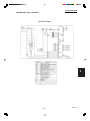
1. Specifications
1-1 Unit Specifications
4-Way Air Discharge Semi-Concealed Type
MODEL No.
1
2
3
4
5
Indoor Unit
XH2672R
Outdoor Unit
C2672R
230 - 208 V / 1 Phase / 60 Hz
POWER SOURCE
Cooling
PERFORMANCE
Capacity * [minimum~muximum]
BTU / h
24,800 [9,500~24,800]
(17˚F)**
BTU / h
Moisture removal (High)
Pints / h
8.1
Air circulation (H / M / L) 230 V
CFM
710 / 530 / 450
External Static Pressure
in. Aq
S.E.E.R. / H.S.P.F. (Region 4)
BTU / Wh
14.1
ELECTRICAL RATINGS
Voltage rating
V
230
208
Available voltage range
V
VAC 187 - 253
Max. Running amperes*
A
15.6
17.3
Power input
W
2,920
2,920
(17˚F)**
W
Back-up Heater
kW
Maximum overcurrent protection (Indoor/Outdoor)
A
15 / 30
FEATURES
Microprocessor
Controls
Low ambient control
Built-in 0˚F
Fan speeds Indoor / Outdoor
3 and Automatic control / Variable
RCS-SH80UG / RCS-TM80BG
Optional Wired Remote Controller
Optional Wireless Remote Controller
RCS-SH80UA. WL / RCS-BH80UA. WL
/ Automatic (Vertical )
Air deflection (Horizontal / Vertical )
Air filter
Washable, long life (2,500 hr)
Max.head 2-33/64 in. above drain connection (25A , OD32mm)
Drain pump (Drain connection)
Compressor
Rotary(SANYO)
Indoor - Hi/Me/Lo
dB - A
38 / 35 / 31
Operation sound
Outdoor - Hi
dB - A
49
Refrigerant control
Electronic Expansion Valve (MOV)
REFRIGERANT TUBING
Limit of tubing length
ft. (m)
165 (50)
Limit of tubing length at shipment
ft. (m)
10~100 (3~30)
Limit of elevation difference
ft. (m)
Outdoor unit is higher than indoor unit : 100 (30)
between the two units
ft. (m)
Outdoor unit is lower than indoor unit : 50 (15)
Refrigerant tube
Narrow tube
in. (mm)
3 / 8 (6.35)
outer diameter
Wide tube
in. (mm)
5 / 8 (15.88)
Refrigerant amount at shipment
lbs. (kg)
4.19 (1.9) - R410A
Indoor unit (Include panel)
Outdoor unit
DIMENSIONS & WEIGHT
Unit dimensions
Height
in. (mm)
13-5/16 (338)
30- 23/32 (780)
Width
in. (mm)
33-55/64 (860)
37 (940)
Depth
in. (mm)
33-55/64 (860)
13- 3/8 (340)
Package dimensions
Body
Panel
Outdoor unit
Height
in. (mm) 11-9/64 (283)
4-3/32 (104)
34- 31/32 (888)
Width
in. (mm)
32-7/8 (835)
37-61/64 (964) 39- 31/32 (1,015)
Depth
in. (mm) 33-9/32 (845)
39-21/64 (999)
16- 3/32 (409)
Net weight
lbs. (kg)
49 (22)
11 (5)
128 (58)
Shipping weight
lbs. (kg)
57 (26)
18 (8)
148 (67)
Shipping volume
cu.ft. (m 3 )
7.1 (0.200)
3.6 (0.100)
13.0 (0.369)
DATA SUBJECT TO CHANGE WITHOUT NOTICE.
Cooling:
Rating conditions (*) : Room temperature 80 °F DB / 67 °F WB, Ambient temperature 95 °F DB / 75 °F WB
6
Heating:
Rating conditions (*) : Room temperature 70 °F DB / 60 °F WB, Ambient temperature 47 °F DB / 43 °F WB
Low temp conditions (**) : Room temperature 70 °F DB / 60 °F WB, Ambient temperature 17 °F DB / 15 °F WB
SM831148
I-12
1. Specifications
1-1 Unit Specifications
4-Way Air Discharge Semi-Concealed Type
MODEL No.
Indoor Unit
XH3672R
Outdoor Unit
C3672R
230 - 208 V / 1 Phase / 60 Hz
POWER SOURCE
Cooling
PERFORMANCE
Capacity * [minimum~muximum]
BTU / h
32,600 [9,500~32,600]
(17˚F)**
BTU / h
Moisture removal (High)
Pints / h
10.6
Air circulation (H / M / L) 230 V
CFM
1050 / 840 / 720
External Static Pressure
in. Aq
S.E.E.R. / H.S.P.F. (Region 4)
BTU / Wh
14.6
ELECTRICAL RATINGS
Voltage rating
V
230
208
Available voltage range
V
VAC 187 - 253
Max. Running amperes*
A
18.7
20.7
Power input
W
3,950
3,950
(17˚F)**
W
Back-up Heater
kW
Maximum overcurrent protection (Indoor/Outdoor)
A
15 / 35
FEATURES
Microprocessor
Controls
Low ambient control
Built-in 0˚F
Fan speeds Indoor / Outdoor
3 and Automatic control / Variable
RCS-SH80UG / RCS-TM80BG
Optional Wired Remote Controller
Optional Wireless Remote Controller
RCS-SH80UA. WL / RCS-BH80UA. WL
/ Automatic (Vertical )
Air deflection (Horizontal / Vertical )
Air filter
Washable, long life (2,500 hr)
Max.head 2-33/64 in. above drain connection (25A , OD32mm)
Drain pump (Drain connection)
Compressor
Rotary(SANYO)
Indoor - Hi/Me/Lo
dB - A
44 / 37 / 33
Operation sound
Outdoor - Hi
dB - A
52
Refrigerant control
Electronic Expansion Valve (MOV)
REFRIGERANT TUBING
Limit of tubing length
ft. (m)
165 (50)
Limit of tubing length at shipment
ft. (m)
10~100 (3~30)
Limit of elevation difference
ft. (m)
Outdoor unit is higher than indoor unit : 100 (30)
between the two units
ft. (m)
Outdoor unit is lower than indoor unit : 50 (15)
Refrigerant tube
Narrow tube
in. (mm)
3 / 8 (6.35)
outer diameter
Wide tube
in. (mm)
5 / 8 (15.88)
Refrigerant amount at shipment
lbs. (kg)
6.17 (2.8) - R410A
Indoor unit (Include panel)
Outdoor unit
DIMENSIONS & WEIGHT
Unit dimensions
Height
in. (mm)
14-31/64 (368)
30- 23/32 (780)
Width
in. (mm)
45-9/32 (1,150)
37 (940)
Depth
in. (mm)
33-55/64 (860)
13- 3/8 (340)
Package dimensions
Body
Panel
Outdoor unit
Height
in. (mm) 12-13/32 (315)
4-3/32 (104)
34- 31/32 (888)
Width
in. (mm) 44-19/64 (1,125) 49-31/64 (1,257) 39- 31/32 (1,015)
Depth
in. (mm) 33-9/32 (845)
39-21/64 (999)
16- 3/32 (409)
Net weight
lbs. (kg)
60 (27)
16 (7)
143 (65)
Shipping weight
lbs. (kg)
71 (32)
22 (10)
161 (73)
Shipping volume
cu.ft. (m 3 )
10.6 (0.299)
4.6 (0.131)
13.0 (0.369)
DATA SUBJECT TO CHANGE WITHOUT NOTICE.
1
2
3
4
5
Cooling:
Rating conditions (*) : Room temperature 80 °F DB / 67 °F WB, Ambient temperature 95 °F DB / 75 °F WB
Heating:
Rating conditions (*) : Room temperature 70 °F DB / 60 °F WB, Ambient temperature 47 °F DB / 43 °F WB
Low temp conditions (**) : Room temperature 70 °F DB / 60 °F WB, Ambient temperature 17 °F DB / 15 °F WB
SM831148
I-13
6
1. Specifications
1-1 Unit Specifications
4-Way Air Discharge Semi-Concealed Type
MODEL No.
1
2
3
4
5
Indoor Unit
XH4272R
Outdoor Unit
C4272R
230 - 208 V / 1 Phase / 60 Hz
POWER SOURCE
Cooling
PERFORMANCE
Capacity * [minimum~muximum]
BTU / h
39,500 [9,500~39,500]
(17˚F)**
BTU / h
Moisture removal (High)
Pints / h
12.6
Air circulation (H / M / L) 230 V
CFM
1050 / 840 / 720
External Static Pressure
in. Aq
S.E.E.R. / H.S.P.F. (Region 4)
BTU / Wh
14.6
ELECTRICAL RATINGS
Voltage rating
V
230
208
Available voltage range
V
VAC 187 - 253
Max. Running amperes*
A
23.0
25.4
Power input
W
4,520
4,520
(17˚F)**
W
Back-up Heater
kW
Maximum overcurrent protection (Indoor/Outdoor)
A
15 / 40
FEATURES
Microprocessor
Controls
Low ambient control
Built-in 0˚F
Fan speeds Indoor / Outdoor
3 and Automatic control / Variable
RCS-SH80UG / RCS-TM80BG
Optional Wired Remote Controller
Optional Wireless Remote Controller
RCS-SH80UA. WL / RCS-BH80UA. WL
/ Automatic (Vertical )
Air deflection (Horizontal / Vertical )
Air filter
Washable, long life (2,500 hr)
Max.head 2-33/64 in. above drain connection (25A , OD32mm)
Drain pump (Drain connection)
Compressor
Rotary(SANYO)
Indoor - Hi/Me/Lo
dB - A
45 / 38 / 34
Operation sound
Outdoor - Hi
dB - A
53
Refrigerant control
Electronic Expansion Valve (MOV)
REFRIGERANT TUBING
Limit of tubing length
ft. (m)
165 (50)
Limit of tubing length at shipment
ft. (m)
10~100 (3~30)
Limit of elevation difference
ft. (m)
Outdoor unit is higher than indoor unit : 100 (30)
between the two units
ft. (m)
Outdoor unit is lower than indoor unit : 50 (15)
Refrigerant tube
Narrow tube
in. (mm)
3 / 8 (6.35)
outer diameter
Wide tube
in. (mm)
5 / 8 (15.88)
Refrigerant amount at shipment
lbs. (kg)
7.94 (3.6) - R410A
Indoor unit (Include panel)
Outdoor unit
DIMENSIONS & WEIGHT
Unit dimensions
Height
in. (mm)
14-31/64 (368)
48-7/16 (1,230 )
Width
in. (mm)
45-9/32 (1,150)
37 (940)
Depth
in. (mm)
33-55/64 (860)
13- 3/8 (340)
Package dimensions
Body
Panel
Outdoor unit
Height
in. (mm) 12-13/32 (315)
4-3/32 (104)
52-3/8 (1,330 )
Width
in. (mm) 44-19/64 (1,125) 49-31/64 (1,257) 39- 31/32 (1,015)
Depth
in. (mm) 33-9/32 (845)
39-21/64 (999)
16- 3/32 (409)
Net weight
lbs. (kg)
60 (27)
16 (7)
220 (100)
Shipping weight
lbs. (kg)
71 (32)
22 (10)
240 (109 )
Shipping volume
cu.ft. (m 3 )
10.6 (0.299)
4.6 (0.131)
19.5 (0.552 )
DATA SUBJECT TO CHANGE WITHOUT NOTICE.
Cooling:
Rating conditions (*) : Room temperature 80 °F DB / 67 °F WB, Ambient temperature 95 °F DB / 75 °F WB
6
Heating:
Rating conditions (*) : Room temperature 70 °F DB / 60 °F WB, Ambient temperature 47 °F DB / 43 °F WB
Low temp conditions (**) : Room temperature 70 °F DB / 60 °F WB, Ambient temperature 17 °F DB / 15 °F WB
SM831148
I-14
1. Specifications
1-1 Unit Specifications
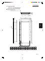
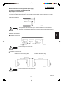
Concealed-Duct Type
MODEL No.
Indoor Unit
UH2672R
Outdoor Unit
CH2672R
230 - 208 V / 1 Phase / 60 Hz
POWER SOURCE
Cooling
Heating
PERFORMANCE
Capacity * [minimum~muximum]
BTU / h 24,000 [9,500~24,000]
28,600 [8,000~28,600]
(17˚F)**
BTU / h
17,100
Moisture removal (High)
Pints / h
7.7
Air circulation (H / M / L) 230 V
CFM
670 / 530 / 460
External Static Pressure
in. Aq
0.2:at shipment / 0.4:using jumper cable
S.E.E.R. / H.S.P.F. (Region 4)
BTU / Wh
14.0
9.7
ELECTRICAL RATINGS
Voltage rating
V
230
208
230
208
Available voltage range
V
VAC 187 - 253
VAC 187 - 253
Max. Running amperes*
A
13.6
15.0
12.5
13.8
Power input
W
2,600
2,600
2,400
2,400
(17˚F)**
W
1,980
1,980
Back-up Heater
kW
Maximum overcurrent protection (Indoor/Outdoor)
A
15 / 30
FEATURES
Microprocessor
Controls
Low ambient control
Built-in 0˚F
Fan speeds Indoor / Outdoor
3 and Automatic control / Variable
RCS-SH80UG / RCS-TM80BG
Optional Wired Remote Controller
Optional Wireless Remote Controller
RCS-BH80UA. WL
Air deflection (Horizontal / Vertical )
Air filter
Max.head 2-33/64 in. above drain connection (25A , OD32mm)
Drain pump (Drain connection)
Compressor
Rotary(SANYO)
Indoor - Hi/Me/Lo
dB - A
34 / 30 / 27
Operation sound
Outdoor - Hi
dB - A
49
Refrigerant control
Electronic Expansion Valve (MOV)
REFRIGERANT TUBING
Limit of tubing length
ft. (m)
165 (50)
Limit of tubing length at shipment
ft. (m)
10~100 (3~30)
Limit of elevation difference
ft. (m)
Outdoor unit is higher than indoor unit : 100 (30)
between the two units
ft. (m)
Outdoor unit is lower than indoor unit : 50 (15)
Refrigerant tube
Narrow tube
in. (mm)
3 / 8 (6.35)
outer diameter
Wide tube
in. (mm)
5 / 8 (15.88)
Refrigerant amount at shipment
lbs. (kg)
4.19 (1.9) - R410A
Indoor unit
Outdoor unit
DIMENSIONS & WEIGHT
Unit dimensions
Height
in. (mm)
12-7/32 (310)
30- 23/32 (780)
Width
in. (mm)
39-3/8 (1,000)
37 (940)
Depth
in. (mm)
24-13/16 (630)
13- 3/8 (340)
Package dimensions
Indoor unit
Outdoor unit
Height
in. (mm)
14-3/32 (358)
34- 31/32 (888)
Width
in. (mm)
46-7/8 (1,191)
39- 31/32 (1,015)
Depth
in. (mm)
30-13/16 (783)
16- 3/32 (409)
Net weight
lbs. (kg)
71 (32)
128 (58)
Shipping weight
lbs. (kg)
82 (37)
148 (67)
Shipping volume
cu.ft. (m 3 )
11.8 (0.334)
13.0 (0.369)
DATA SUBJECT TO CHANGE WITHOUT NOTICE.
1
2
3
4
5
Cooling:
Rating conditions (*) : Room temperature 80 °F DB / 67 °F WB, Ambient temperature 95 °F DB / 75 °F WB
Heating:
Rating conditions (*) : Room temperature 70 °F DB / 60 °F WB, Ambient temperature 47 °F DB / 43 °F WB
Low temp conditions (**) : Room temperature 70 °F DB / 60 °F WB, Ambient temperature 17 °F DB / 15 °F WB
SM831148
I-15
6
1. Specifications
1-1 Unit Specifications
Concealed-Duct Type
MODEL No.
1
2
3
4
5
Indoor Unit
UH3672R
Outdoor Unit
CH3672R
230 - 208 V / 1 Phase / 60 Hz
POWER SOURCE
Cooling
Heating
PERFORMANCE
Capacity * [minimum~muximum]
BTU / h 31,200 [9,500~31,200]
36,200 [8,000~36,200]
(17˚F)**
BTU / h
20,200
Moisture removal (High)
Pints / h
10.0
Air circulation (H / M / L) 230 V
CFM
670 / 530 / 460
External Static Pressure
in. Aq
0.24:at shipment / 0.4:using jumper cable
S.E.E.R. / H.S.P.F. (Region 4)
BTU / Wh
13.9
8.7
ELECTRICAL RATINGS
Voltage rating
V
230
208
230
208
Available voltage range
V
VAC 187 - 253
VAC 187 - 253
Max. Running amperes*
A
18.6
20.6
15.9
17.6
Power input
W
3,920
3,920
3,340
3,340
(17˚F)**
W
2,570
2,570
Back-up Heater
kW
Maximum overcurrent protection (Indoor/Outdoor)
A
15 / 35
FEATURES
Microprocessor
Controls
Low ambient control
Built-in 0˚F
Fan speeds Indoor / Outdoor
3 and Automatic control / Variable
RCS-SH80UG / RCS-TM80BG
Optional Wired Remote Controller
RCS-BH80UA. WL
Optional Wireless Remote Controller
Air deflection (Horizontal / Vertical )
Air filter
Max.head 2-33/64 in. above drain connection (25A , OD32mm)
Drain pump (Drain connection)
Compressor
Rotary(SANYO)
Indoor - Hi/Me/Lo
dB - A
38 / 33 / 31
Operation sound
Outdoor - Hi
dB - A
52
Refrigerant control
Electronic Expansion Valve (MOV)
REFRIGERANT TUBING
Limit of tubing length
ft. (m)
165 (50)
Limit of tubing length at shipment
ft. (m)
10~100 (3~30)
Limit of elevation difference
ft. (m)
Outdoor unit is higher than indoor unit : 100 (30)
between the two units
ft. (m)
Outdoor unit is lower than indoor unit : 50 (15)
Refrigerant tube
Narrow tube
in. (mm)
3 / 8 (6.35)
outer diameter
Wide tube
in. (mm)
5 / 8 (15.88)
Refrigerant amount at shipment
lbs. (kg)
6.17 (2.8) - R410A
Indoor unit
Outdoor unit
DIMENSIONS & WEIGHT
Unit dimensions
Height
in. (mm)
12-7/32 (310)
30- 23/32 (780)
Width
in. (mm)
58-9/32 (1,480)
37 (940)
Depth
in. (mm)
24-13/16 (630)
13- 3/8 (340)
Package dimensions
Indoor unit
Outdoor unit
Height
in. (mm)
14-3/32 (358)
34- 31/32 (888)
Width
in. (mm)
65-25/32 (1,671)
39- 31/32 (1,015)
Depth
in. (mm)
30-13/16 (783)
16- 3/32 (409)
Net weight
lbs. (kg)
104 (47)
143 (65)
Shipping weight
lbs. (kg)
115 (52)
161 (73)
Shipping volume
cu.ft. (m 3 )
16.5 0.468)
13.0 (0.369)
DATA SUBJECT TO CHANGE WITHOUT NOTICE.
Cooling:
Rating conditions (*) : Room temperature 80 °F DB / 67 °F WB, Ambient temperature 95 °F DB / 75 °F WB
6
Heating:
Rating conditions (*) : Room temperature 70 °F DB / 60 °F WB, Ambient temperature 47 °F DB / 43 °F WB
Low temp conditions (**) : Room temperature 70 °F DB / 60 °F WB, Ambient temperature 17 °F DB / 15 °F WB
SM831148
I-16
1. Specifications
1-1 Unit Specifications
Concealed-Duct Type
MODEL No.
Indoor Unit
UH2672R
Outdoor Unit
C2672R
230 - 208 V / 1 Phase / 60 Hz
POWER SOURCE
Cooling
PERFORMANCE
Capacity * [minimum~muximum]
BTU / h
24,000 [9,500~24,000]
—
(17˚F)**
BTU / h
Moisture removal (High)
Pints / h
7.7
Air circulation (H / M / L) 230 V
CFM
670 / 530 / 460
External Static Pressure
in. Aq
0.2:at shipment / 0.4:using jumper cable
S.E.E.R. / H.S.P.F. (Region 4)
BTU / Wh
14.0
ELECTRICAL RATINGS
Voltage rating
V
230
208
Available voltage range
V
VAC 187 - 253
Max. Running amperes*
A
13.6
15.0
Power input
W
2,600
2,600
—
(17˚F)**
W
—
Back-up Heater
kW
Maximum overcurrent protection (Indoor/Outdoor)
A
15 / 30
FEATURES
Microprocessor
Controls
Low ambient control
Built-in 0˚F
Fan speeds Indoor / Outdoor
3 and Automatic control / Variable
RCS-SH80UG / RCS-TM80BG
Optional Wired Remote Controller
Optional Wireless Remote Controller
RCS-BH80UA. WL
Air deflection (Horizontal / Vertical )
—
Air filter
—
Max.head 2-33/64 in. above drain connection (25A , OD32mm)
Drain pump (Drain connection)
Compressor
Rotary(SANYO)
Indoor - Hi/Me/Lo
dB - A
34 / 30 / 27
Operation sound
Outdoor - Hi
dB - A
49
Refrigerant control
Electronic Expansion Valve (MOV)
REFRIGERANT TUBING
Limit of tubing length
ft. (m)
165 (50)
Limit of tubing length at shipment
ft. (m)
10~100 (3~30)
Limit of elevation difference
ft. (m)
Outdoor unit is higher than indoor unit : 100 (30)
between the two units
ft. (m)
Outdoor unit is lower than indoor unit : 50 (15)
Refrigerant tube
Narrow tube
in. (mm)
3 / 8 (6.35)
outer diameter
Wide tube
in. (mm)
5 / 8 (15.88)
Refrigerant amount at shipment
lbs. (kg)
4.19 (1.9) - R410A
Indoor unit
Outdoor unit
DIMENSIONS & WEIGHT
Unit dimensions
Height
in. (mm)
12-7/32 (310)
30- 23/32 (780)
Width
in. (mm)
39-3/8 (1,000)
37 (940)
Depth
in. (mm)
24-13/16 (630)
13- 3/8 (340)
Package dimensions
Indoor unit
Outdoor unit
Height
in. (mm)
14-3/32 (358)
34- 31/32 (888)
Width
in. (mm)
46-7/8 (1,191)
39- 31/32 (1,015)
Depth
in. (mm)
30-13/16 (783)
16- 3/32 (409)
Net weight
lbs. (kg)
71 (32)
128 (58)
Shipping weight
lbs. (kg)
82 (37)
148 (67)
Shipping volume
cu.ft. (m 3 )
11.8 (0.334)
13.0 (0.369)
DATA SUBJECT TO CHANGE WITHOUT NOTICE.
1
2
3
4
5
Cooling:
Rating conditions (*) : Room temperature 80 °F DB / 67 °F WB, Ambient temperature 95 °F DB / 75 °F WB
Heating:
Rating conditions (*) : Room temperature 70 °F DB / 60 °F WB, Ambient temperature 47 °F DB / 43 °F WB
Low temp conditions (**) : Room temperature 70 °F DB / 60 °F WB, Ambient temperature 17 °F DB / 15 °F WB
SM831148
I-17
6
1. Specifications
1-1 Unit Specifications
Concealed-Duct Type
MODEL No.
1
2
3
4
5
Indoor Unit
UH3672R
Outdoor Unit
C3672R
230 - 208 V / 1 Phase / 60 Hz
POWER SOURCE
Cooling
PERFORMANCE
Capacity * [minimum~muximum]
BTU / h
31,200 [9,500~31,200]
—
(17˚F)**
BTU / h
Moisture removal (High)
Pints / h
10.0
Air circulation (H / M / L) 230 V
CFM
670 / 530 / 460
External Static Pressure
in. Aq
0.24:at shipment / 0.4:using jumper cable
S.E.E.R. / H.S.P.F. (Region 4)
BTU / Wh
13.9
ELECTRICAL RATINGS
Voltage rating
V
230
208
Available voltage range
V
VAC 187 - 253
Max. Running amperes*
A
18.6
20.6
Power input
W
3,920
3,920
—
(17˚F)**
W
—
Back-up Heater
kW
Maximum overcurrent protection (Indoor/Outdoor)
A
15 / 35
FEATURES
Microprocessor
Controls
Microprocessor
Low ambient control
Built-in 0˚F
Fan speeds Indoor / Outdoor
3 and Automatic control / Variable
RCS-SH80UG / RCS-TM80BG
Optional Wired Remote Controller
Optional Wireless Remote Controller
RCS-SH1UA / RCS-BH80UA. WL
Air deflection (Horizontal / Vertical )
—
Air filter
—
Max.head 2-33/64 in. above drain connection (25A , OD32mm)
Drain pump (Drain connection)
Compressor
Rotary(SANYO)
Indoor - Hi/Me/Lo
dB - A
38 / 33 / 31
Operation sound
Outdoor - Hi
dB - A
52
Refrigerant control
Electronic Expansion Valve (MOV)
REFRIGERANT TUBING
Limit of tubing length
ft. (m)
165 (50)
Limit of tubing length at shipment
ft. (m)
10~100 (3~30)
Limit of elevation difference
ft. (m)
Outdoor unit is higher than indoor unit : 100 (30)
between the two units
ft. (m)
Outdoor unit is lower than indoor unit : 50 (15)
Refrigerant tube
Narrow tube
in. (mm)
3 / 8 (6.35)
outer diameter
Wide tube
in. (mm)
5 / 8 (15.88)
Refrigerant amount at shipment
lbs. (kg)
6.17 (2.8) - R410A
Indoor unit
Outdoor unit
DIMENSIONS & WEIGHT
Unit dimensions
Height
in. (mm)
12-7/32 (310)
30- 23/32 (780)
Width
in. (mm)
58-9/32 (1,480)
37 (940)
Depth
in. (mm)
24-13/16 (630)
13- 3/8 (340)
Package dimensions
Indoor unit
Outdoor unit
Height
in. (mm)
14-3/32 (358)
34- 31/32 (888)
Width
in. (mm)
65-25/32 (1,671)
39- 31/32 (1,015)
Depth
in. (mm)
30-13/16 (783)
16- 3/32 (409)
Net weight
lbs. (kg)
104 (47)
143 (65)
Shipping weight
lbs. (kg)
115 (52)
161 (73)
Shipping volume
cu.ft. (m 3 )
16.5 0.468)
13.0 (0.369)
DATA SUBJECT TO CHANGE WITHOUT NOTICE.
Cooling:
Rating conditions (*) : Room temperature 80 °F DB / 67 °F WB, Ambient temperature 95 °F DB / 75 °F WB
6
Heating:
Rating conditions (*) : Room temperature 70 °F DB / 60 °F WB, Ambient temperature 47 °F DB / 43 °F WB
Low temp conditions (**) : Room temperature 70 °F DB / 60 °F WB, Ambient temperature 17 °F DB / 15 °F WB
SM831148
I-18
1. Specifications
1-1 Unit Specifications
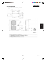
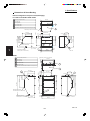
Ceiling-Mounted Type
MODEL No.
Indoor Unit
Outdoor Unit
POWER SOURCE
PERFORMANCE
Capacity * [minimum~muximum]
BTU / h
(17˚F)**
BTU / h
Moisture removal (High)
Pints / h
Air circulation (H / M / L) 230 V
CFM
External Static Pressure
in. Aq
S.E.E.R. / H.S.P.F. (Region 4)
BTU / Wh
ELECTRICAL RATINGS
Voltage rating
V
Available voltage range
V
Max. Running amperes* (Without Back-up Heater)
A
Power input
W
(17˚F)**
W
Back-up Heater
kW
Maximum overcurrent protection (Indoor/Outdoor)
A
FEATURES
Controls
Low ambient control
Fan speeds Indoor / Outdoor
Optional Wired Remote Controller
Optional Wireless Remote Controller
Air deflection (Horizontal / Vertical )
Air filter
Drain pump (Drain connection)
Compressor
Indoor - Hi/Me/Lo
dB - A
Operation sound
Outdoor - Hi
dB - A
Refrigerant control
REFRIGERANT TUBING
Limit of tubing length
ft. (m)
Limit of tubing length at shipment
ft. (m)
Limit of elevation difference
ft. (m)
between the two units
ft. (m)
Refrigerant tube
Narrow tube
in. (mm)
outer diameter
Wide tube
in. (mm)
Refrigerant amount at shipment
lbs. (kg)
DIMENSIONS & WEIGHT
Unit dimensions
Height
in. (mm)
Width
in. (mm)
Depth
in. (mm)
Package dimensions
Height
in. (mm)
Width
in. (mm)
Depth
in. (mm)
Net weight
lbs. (kg)
Shipping weight
lbs. (kg)
Shipping volume
cu.ft. (m 3 )
THH2672R
CH2672R
230 - 208 V / 1 Phase / 60 Hz
Cooling
Heating
24,400 [9,500~24,400]
30,800 [8,000~30,800]
17,900
7.7
550 / 490 / 460
14.5
10.3
230
208
VAC 187 - 253
15.6
17.3
2,880
2,880
230
208
VAC 187 - 253
16.4
18.1
3,000
3,000
2,190
2,190
1.8
1.47
15 / 30
Microprocessor
Built-in 0˚F
3 and Automatic control / Variable
RCS-SH80UG / RCS-TM80BG
RCS-SH80UA. WL / RCS-BH80UA. WL
/ Automatic (Vertical )
Washable, long life (2,500 hr)
(20A , OD26mm)
Rotary(SANYO)
39 / 37 / 33
49
Electronic Expansion Valve (MOV)
165 (50)
10~100 (3~30)
Outdoor unit is higher than indoor unit : 100 (30)
Outdoor unit is lower than indoor unit : 50 (15)
3 / 8 (6.35)
5 / 8 (15.88)
4.19 (1.9) - R410A
Indoor unit
Outdoor unit
7-17/32 (190)
30- 23/32 (780)
51-3/16 (1,300)
37 (940)
26-3/8 (670)
13- 3/8 (340)
Indoor unit
Outdoor unit
9-7/16 (240)
34- 31/32 (888)
54-19/32 (1,387)
39- 31/32 (1,015)
31-1/16 (789)
16- 3/32 (409)
64 (29)
128 (58)
75 (34)
148 (67)
8.9 (0.253)
13.0 (0.369)
DATA SUBJECT TO CHANGE WITHOUT NOTICE.
1
2
3
4
5
Cooling:
Rating conditions (*) : Room temperature 80 °F DB / 67 °F WB, Ambient temperature 95 °F DB / 75 °F WB
Heating:
Rating conditions (*) : Room temperature 70 °F DB / 60 °F WB, Ambient temperature 47 °F DB / 43 °F WB
Low temp conditions (**) : Room temperature 70 °F DB / 60 °F WB, Ambient temperature 17 °F DB / 15 °F WB
SM831148
I-19
6
1. Specifications
1-1 Unit Specifications
Ceiling-Mounted Type
MODEL No.
1
2
3
4
5
Indoor Unit
Outdoor Unit
POWER SOURCE
PERFORMANCE
Capacity * [minimum~muximum]
BTU / h
(17˚F)**
BTU / h
Moisture removal (High)
Pints / h
Air circulation (H / M / L) 230 V
CFM
External Static Pressure
in. Aq
S.E.E.R. / H.S.P.F. (Region 4)
BTU / Wh
ELECTRICAL RATINGS
Voltage rating
V
Available voltage range
V
Max. Running amperes* (Without Back-up Heater)
A
Power input
W
(17˚F)**
W
Back-up Heater
kW
Maximum overcurrent protection (Indoor/Outdoor)
A
FEATURES
Controls
Microprocessor
Low ambient control
Fan speeds Indoor / Outdoor
Optional Wired Remote Controller
Optional Wireless Remote Controller
Air deflection (Horizontal / Vertical )
Air filter
Drain pump (Drain connection)
Compressor
Indoor - Hi/Me/Lo
dB - A
Operation sound
Outdoor - Hi
dB - A
Refrigerant control
REFRIGERANT TUBING
Limit of tubing length
ft. (m)
Limit of tubing length at shipment
ft. (m)
Limit of elevation difference
ft. (m)
between the two units
ft. (m)
Refrigerant tube
Narrow tube
in. (mm)
outer diameter
Wide tube
in. (mm)
Refrigerant amount at shipment
lbs. (kg)
DIMENSIONS & WEIGHT
Unit dimensions
Height
in. (mm)
Width
in. (mm)
Depth
in. (mm)
Package dimensions
Height
in. (mm)
Width
in. (mm)
Depth
in. (mm)
Net weight
lbs. (kg)
Shipping weight
lbs. (kg)
Shipping volume
cu.ft. (m 3 )
TH2672R
CH2672R
230 - 208 V / 1 Phase / 60 Hz
Cooling
Heating
24,400 [9,500~24,400]
30,800 [8,000~30,800]
17,900
7.7
550 / 490 / 460
14.5
10.3
230
208
VAC 187 - 253
15.6
17.3
2,880
2,880
230
208
VAC 187 - 253
16.4
18.1
3,000
3,000
2,190
2,190
15 / 30
Microprocessor
Built-in 0˚F
3 and Automatic control / Variable
RCS-SH80UG / RCS-TM80BG
RCS-SH80UA. WL / RCS-BH80UA. WL
/ Automatic (Vertical )
Washable, long life (2,500 hr)
(20A , OD26mm)
Rotary(SANYO)
39 / 37 / 33
49
Electronic Expansion Valve (MOV)
165 (50)
10~100 (3~30)
Outdoor unit is higher than indoor unit : 100 (30)
Outdoor unit is lower than indoor unit : 50 (15)
3 / 8 (6.35)
5 / 8 (15.88)
4.19 (1.9) - R410A
Indoor unit
Outdoor unit
7-17/32 (190)
30- 23/32 (780)
51-3/16 (1,300)
37 (940)
26-3/8 (670)
13- 3/8 (340)
Indoor unit
Outdoor unit
9-7/16 (240)
34- 31/32 (888)
54-19/32 (1,387)
39- 31/32 (1,015)
31-1/16 (789)
16- 3/32 (409)
57 (26)
128 (58)
68 (31)
148 (67)
8.9 (0.253)
13.0 (0.369)
DATA SUBJECT TO CHANGE WITHOUT NOTICE.
Cooling:
Rating conditions (*) : Room temperature 80 °F DB / 67 °F WB, Ambient temperature 95 °F DB / 75 °F WB
6
Heating:
Rating conditions (*) : Room temperature 70 °F DB / 60 °F WB, Ambient temperature 47 °F DB / 43 °F WB
Low temp conditions (**) : Room temperature 70 °F DB / 60 °F WB, Ambient temperature 17 °F DB / 15 °F WB
SM831148
I-20
1. Specifications
1-1 Unit Specifications
Ceiling-Mounted Type
MODEL No.
Indoor Unit
Outdoor Unit
POWER SOURCE
PERFORMANCE
Capacity * [minimum~muximum]
BTU / h
(17˚F)**
BTU / h
Moisture removal (High)
Pints / h
Air circulation (H / M / L) 230 V
CFM
External Static Pressure
in. Aq
S.E.E.R. / H.S.P.F. (Region 4)
BTU / Wh
ELECTRICAL RATINGS
Voltage rating
V
Available voltage range
V
Max. Running amperes*
A
Power input
W
(17˚F)**
W
Back-up Heater
kW
Maximum overcurrent protection (Indoor/Outdoor)
A
FEATURES
Controls
Microprocessor
Low ambient control
Fan speeds Indoor / Outdoor
Optional Wired Remote Controller
Optional Wireless Remote Controller
Air deflection (Horizontal / Vertical )
Air filter
Drain pump (Drain connection)
Compressor
Indoor - Hi/Me/Lo
dB - A
Operation sound
Outdoor - Hi
dB - A
Refrigerant control
REFRIGERANT TUBING
Limit of tubing length
ft. (m)
Limit of tubing length at shipment
ft. (m)
Limit of elevation difference
ft. (m)
between the two units
ft. (m)
Refrigerant tube
Narrow tube
in. (mm)
outer diameter
Wide tube
in. (mm)
Refrigerant amount at shipment
lbs. (kg)
DIMENSIONS & WEIGHT
Unit dimensions
Height
in. (mm)
Width
in. (mm)
Depth
in. (mm)
Package dimensions
Height
in. (mm)
Width
in. (mm)
Depth
in. (mm)
Net weight
lbs. (kg)
Shipping weight
lbs. (kg)
Shipping volume
cu.ft. (m 3 )
THH3672R
CH3672R
230 - 208 V / 1 Phase / 60 Hz
Cooling
Heating
31,200 [9,500~31,200]
37,400 [8,000~37,400]
21,000
10.0
1100 / 930 / 750
15.1
9.6
230
208
VAC 187 - 253
18.2
20.1
3,840
3,840
230
208
VAC 187 - 253
15.6
17.3
3,250
3,250
2,470
2,470
2.4
1.95
15 / 35
Microprocessor
Built-in 0˚F
3 and Automatic control / Variable
RCS-SH80UG / RCS-TM80BG
RCS-SH80UA. WL / RCS-BH80UA. WL
/ Automatic (Vertical )
Washable, long life (2,500 hr)
(20A , OD26mm)
Rotary(SANYO)
42 / 40 / 35
52
Electronic Expansion Valve (MOV)
165 (50)
10~100 (3~30)
Outdoor unit is higher than indoor unit : 100 (30)
Outdoor unit is lower than indoor unit : 50 (15)
3 / 8 (6.35)
5 / 8 (15.88)
6.17 (2.8) - R410A
Indoor unit
Outdoor unit
9-7/16 (240)
30- 23/32 (780)
62-1/32 (1,575)
37 (940)
26-3/8 (670)
13- 3/8 (340)
Indoor unit
Outdoor unit
12-15/32 (317)
34- 31/32 (888)
66-1/16 (1,678)
39- 31/32 (1,015)
31-1/16 (789)
16- 3/32 (409)
90 (41)
143 (65)
104 (47)
161 (73)
14.8 (0.420)
13.0 (0.369)
DATA SUBJECT TO CHANGE WITHOUT NOTICE.
1
2
3
4
5
Cooling:
Rating conditions (*) : Room temperature 80 °F DB / 67 °F WB, Ambient temperature 95 °F DB / 75 °F WB
Heating:
Rating conditions (*) : Room temperature 70 °F DB / 60 °F WB, Ambient temperature 47 °F DB / 43 °F WB
Low temp conditions (**) : Room temperature 70 °F DB / 60 °F WB, Ambient temperature 17 °F DB / 15 °F WB
SM831148
I-21
6
1. Specifications
1-1 Unit Specifications
Ceiling-Mounted Type
MODEL No.
1
2
3
4
5
Indoor Unit
Outdoor Unit
POWER SOURCE
PERFORMANCE
Capacity * [minimum~muximum]
BTU / h
(17˚F)**
BTU / h
Moisture removal (High)
Pints / h
Air circulation (H / M / L) 230 V
CFM
External Static Pressure
in. Aq
S.E.E.R. / H.S.P.F. (Region 4)
BTU / Wh
ELECTRICAL RATINGS
Voltage rating
V
Available voltage range
V
Max. Running amperes*
A
Power input
W
(17˚F)**
W
Back-up Heater
kW
Maximum overcurrent protection (Indoor/Outdoor)
A
FEATURES
Controls
Low ambient control
Fan speeds Indoor / Outdoor
Optional Wired Remote Controller
Optional Wireless Remote Controller
Air deflection (Horizontal / Vertical )
Air filter
Drain pump (Drain connection)
Compressor
Indoor - Hi/Me/Lo
dB - A
Operation sound
Outdoor - Hi
dB - A
Refrigerant control
REFRIGERANT TUBING
Limit of tubing length
ft. (m)
Limit of tubing length at shipment
ft. (m)
Limit of elevation difference
ft. (m)
between the two units
ft. (m)
Refrigerant tube
Narrow tube
in. (mm)
outer diameter
Wide tube
in. (mm)
Refrigerant amount at shipment
lbs. (kg)
DIMENSIONS & WEIGHT
Unit dimensions
Height
in. (mm)
Width
in. (mm)
Depth
in. (mm)
Package dimensions
Height
in. (mm)
Width
in. (mm)
Depth
in. (mm)
Net weight
lbs. (kg)
Shipping weight
lbs. (kg)
Shipping volume
cu.ft. (m 3 )
TH3672R
CH3672R
230 - 208 V / 1 Phase / 60 Hz
Cooling
Heating
31,200 [9,500~31,200]
37,400 [8,000~37,400]
21,000
10.0
1100 / 930 / 750
15.1
9.6
230
208
VAC 187 - 253
18.2
20.1
3,840
3,840
230
208
VAC 187 - 253
15.6
17.3
3,250
3,250
2,470
2,470
15 / 35
Microprocessor
Built-in 0˚F
3 and Automatic control / Variable
RCS-SH80UG / RCS-TM80BG
RCS-SH80UA. WL / RCS-BH80UA. WL
/ Automatic (Vertical )
Washable, long life (2,500 hr)
(20A , OD26mm)
Rotary(SANYO)
42 / 40 / 35
52
Electronic Expansion Valve (MOV)
165 (50)
10~100 (3~30)
Outdoor unit is higher than indoor unit : 100 (30)
Outdoor unit is lower than indoor unit : 50 (15)
3 / 8 (6.35)
5 / 8 (15.88)
6.17 (2.8) - R410A
Indoor unit
Outdoor unit
9-7/16 (240)
30- 23/32 (780)
62-1/32 (1,575)
37 (940)
26-3/8 (670)
13- 3/8 (340)
Indoor unit
Outdoor unit
12-15/32 (317)
34- 31/32 (888)
66-1/16 (1,678)
39- 31/32 (1,015)
31-1/16 (789)
16- 3/32 (409)
84 (38)
143 (65)
97 (44)
161 (73)
14.8 (0.420)
13.0 (0.369)
DATA SUBJECT TO CHANGE WITHOUT NOTICE.
Cooling:
Rating conditions (*) : Room temperature 80 °F DB / 67 °F WB, Ambient temperature 95 °F DB / 75 °F WB
6
Heating:
Rating conditions (*) : Room temperature 70 °F DB / 60 °F WB, Ambient temperature 47 °F DB / 43 °F WB
Low temp conditions (**) : Room temperature 70 °F DB / 60 °F WB, Ambient temperature 17 °F DB / 15 °F WB
SM831148
I-22
1. Specifications
1-1 Unit Specifications
Ceiling-Mounted Type
MODEL No.
Indoor Unit
Outdoor Unit
POWER SOURCE
PERFORMANCE
Capacity * [minimum~muximum]
BTU / h
(17˚F)**
BTU / h
Moisture removal (High)
Pints / h
Air circulation (H / M / L) 230 V
CFM
External Static Pressure
in. Aq
S.E.E.R. / H.S.P.F. (Region 4)
BTU / Wh
ELECTRICAL RATINGS
Voltage rating
V
Available voltage range
V
Max. Running amperes*
A
Power input
W
(17˚F)**
W
Back-up Heater
kW
Maximum overcurrent protection (Indoor/Outdoor)
A
FEATURES
Controls
Low ambient control
Fan speeds Indoor / Outdoor
Optional Wired Remote Controller
Optional Wireless Remote Controller
Air deflection (Horizontal / Vertical )
Air filter
Drain pump (Drain connection)
Compressor
Indoor - Hi/Me/Lo
dB - A
Operation sound
Outdoor - Hi
dB - A
Refrigerant control
REFRIGERANT TUBING
Limit of tubing length
ft. (m)
Limit of tubing length at shipment
ft. (m)
Limit of elevation difference
ft. (m)
between the two units
ft. (m)
Refrigerant tube
Narrow tube
in. (mm)
outer diameter
Wide tube
in. (mm)
Refrigerant amount at shipment
lbs. (kg)
DIMENSIONS & WEIGHT
Unit dimensions
Height
in. (mm)
Width
in. (mm)
Depth
in. (mm)
Package dimensions
Height
in. (mm)
Width
in. (mm)
Depth
in. (mm)
Net weight
lbs. (kg)
Shipping weight
lbs. (kg)
Shipping volume
cu.ft. (m 3 )
TH4272R
CH4272R
230 - 208 V / 1 Phase / 60 Hz
Cooling
Heating
39,000 [9,500~39,000]
44,500 [8,000~44,500]
28,800
12.6
1100 / 930 / 750
15.6
10.2
230
208
VAC 187 - 253
21.1
23.3
4,140
4,140
230
208
VAC 187 - 253
18.6
20.6
3,630
3,630
3,110
3,110
15 / 40
Microprocessor
Built-in 0˚F
3 and Automatic control / Variable
RCS-SH80UG / RCS-TM80BG
RCS-SH80UA. WL / RCS-BH80UA. WL
/ Automatic (Vertical )
Washable, long life (2,500 hr)
(20A , OD26mm)
Rotary(SANYO)
44 / 41 / 37
53
Electronic Expansion Valve (MOV)
165 (50)
10~100 (3~30)
Outdoor unit is higher than indoor unit : 100 (30)
Outdoor unit is lower than indoor unit : 50 (15)
3 / 8 (6.35)
5 / 8 (15.88)
7.94 (3.6) - R410A
Indoor unit
Outdoor unit
9-7/16 (240)
48-7/16 (1,230 )
62-1/32 (1,575)
37 (940)
26-3/8 (670)
13- 3/8 (340)
Indoor unit
Outdoor unit
12-15/32 (317)
52-3/8 (1,330 )
66-1/16 (1,678)
39- 31/32 (1,015)
31-1/16 (789)
16- 3/32 (409)
84 (38)
220 (100)
97 (44)
240 (109 )
14.8 (0.420)
19.5 (0.552 )
DATA SUBJECT TO CHANGE WITHOUT NOTICE.
1
2
3
4
5
Cooling:
Rating conditions (*) : Room temperature 80 °F DB / 67 °F WB, Ambient temperature 95 °F DB / 75 °F WB
Heating:
Rating conditions (*) : Room temperature 70 °F DB / 60 °F WB, Ambient temperature 47 °F DB / 43 °F WB
Low temp conditions (**) : Room temperature 70 °F DB / 60 °F WB, Ambient temperature 17 °F DB / 15 °F WB
SM831148
I-23
6
1. Specifications
1-1 Unit Specifications
Ceiling-Mounted Type
MODEL No.
1
2
3
4
5
Indoor Unit
Outdoor Unit
POWER SOURCE
PERFORMANCE
Capacity * [minimum~muximum]
BTU / h
(17˚F)**
BTU / h
Moisture removal (High)
Pints / h
Air circulation (H / M / L) 230 V
CFM
External Static Pressure
in. Aq
S.E.E.R. / H.S.P.F. (Region 4)
BTU / Wh
ELECTRICAL RATINGS
Voltage rating
V
Available voltage range
V
Max. Running amperes* (Without Back-up Heater)
A
Power input
W
(17˚F)**
W
Back-up Heater
kW
Maximum overcurrent protection (Indoor/Outdoor)
A
FEATURES
Controls
Low ambient control
Fan speeds Indoor / Outdoor
Optional Wired Remote Controller
Optional Wireless Remote Controller
Air deflection (Horizontal / Vertical )
Air filter
Drain pump (Drain connection)
Compressor
Indoor - Hi/Me/Lo
dB - A
Operation sound
Outdoor - Hi
dB - A
Refrigerant control
REFRIGERANT TUBING
Limit of tubing length
ft. (m)
Limit of tubing length at shipment
ft. (m)
Limit of elevation difference
ft. (m)
between the two units
ft. (m)
Refrigerant tube
Narrow tube
in. (mm)
outer diameter
Wide tube
in. (mm)
Refrigerant amount at shipment
lbs. (kg)
DIMENSIONS & WEIGHT
Unit dimensions
Height
in. (mm)
Width
in. (mm)
Depth
in. (mm)
Package dimensions
Height
in. (mm)
Width
in. (mm)
Depth
in. (mm)
Net weight
lbs. (kg)
Shipping weight
lbs. (kg)
Shipping volume
cu.ft. (m 3 )
TH2672R
C2672R
230 - 208 V / 1 Phase / 60 Hz
Cooling
24,400 [9,500~24,400]
7.7
550 / 490 / 460
14.5
230
208
VAC 187 - 253
15.6
2,880
17.3
2,880
15 / 30
Microprocessor
Built-in 0˚F
3 and Automatic control / Variable
RCS-SH80UG / RCS-TM80BG
RCS-SH80UA. WL / RCS-BH80UA. WL
/ Automatic (Vertical )
Washable, long life (2,500 hr)
(20A , OD26mm)
Rotary(SANYO)
39 / 37 / 33
49
Electronic Expansion Valve (MOV)
165 (50)
10~100 (3~30)
Outdoor unit is higher than indoor unit : 100 (30)
Outdoor unit is lower than indoor unit : 50 (15)
3 / 8 (6.35)
5 / 8 (15.88)
4.19 (1.9) - R410A
Indoor unit
Outdoor unit
7-17/32 (190)
30- 23/32 (780)
51-3/16 (1,300)
37 (940)
26-3/8 (670)
13- 3/8 (340)
Indoor unit
Outdoor unit
9-7/16 (240)
34- 31/32 (888)
54-19/32 (1,387)
39- 31/32 (1,015)
31-1/16 (789)
16- 3/32 (409)
57 (26)
128 (58)
68 (31)
148 (67)
8.9 (0.253)
13.0 (0.369)
DATA SUBJECT TO CHANGE WITHOUT NOTICE.
Cooling:
Rating conditions (*) : Room temperature 80 °F DB / 67 °F WB, Ambient temperature 95 °F DB / 75 °F WB
6
Heating:
Rating conditions (*) : Room temperature 70 °F DB / 60 °F WB, Ambient temperature 47 °F DB / 43 °F WB
Low temp conditions (**) : Room temperature 70 °F DB / 60 °F WB, Ambient temperature 17 °F DB / 15 °F WB
SM831148
I-24
1. Specifications
1-1 Unit Specifications
Ceiling-Mounted Type
MODEL No.
Indoor Unit
Outdoor Unit
POWER SOURCE
PERFORMANCE
Capacity * [minimum~muximum]
BTU / h
(17˚F)**
BTU / h
Moisture removal (High)
Pints / h
Air circulation (H / M / L) 230 V
CFM
External Static Pressure
in. Aq
S.E.E.R. / H.S.P.F. (Region 4)
BTU / Wh
ELECTRICAL RATINGS
Voltage rating
V
Available voltage range
V
Max. Running amperes*
A
Power input
W
(17˚F)**
W
Back-up Heater
kW
Maximum overcurrent protection (Indoor/Outdoor)
A
FEATURES
Controls
Low ambient control
Fan speeds Indoor / Outdoor
Optional Wired Remote Controller
Optional Wireless Remote Controller
Air deflection (Horizontal / Vertical )
Air filter
Drain pump (Drain connection)
Compressor
Indoor - Hi/Me/Lo
dB - A
Operation sound
Outdoor - Hi
dB - A
Refrigerant control
REFRIGERANT TUBING
Limit of tubing length
ft. (m)
Limit of tubing length at shipment
ft. (m)
Limit of elevation difference
ft. (m)
between the two units
ft. (m)
Refrigerant tube
Narrow tube
in. (mm)
outer diameter
Wide tube
in. (mm)
Refrigerant amount at shipment
lbs. (kg)
DIMENSIONS & WEIGHT
Unit dimensions
Height
in. (mm)
Width
in. (mm)
Depth
in. (mm)
Package dimensions
Height
in. (mm)
Width
in. (mm)
Depth
in. (mm)
Net weight
lbs. (kg)
Shipping weight
lbs. (kg)
Shipping volume
cu.ft. (m 3 )
TH3672R
C3672R
230 - 208 V / 1 Phase / 60 Hz
Cooling
31,200 [9,500~31,200]
10.0
1100 / 930 / 750
15.1
230
208
VAC 187 - 253
18.2
3,840
20.1
3,840
15 / 35
Microprocessor
Built-in 0˚F
3 and Automatic control / Variable
RCS-SH80UG / RCS-TM80BG
RCS-SH80UA. WL / RCS-BH80UA. WL
/ Automatic (Vertical )
Washable, long life (2,500 hr)
(20A , OD26mm)
Rotary(SANYO)
42 / 40 / 35
52
Electronic Expansion Valve (MOV)
165 (50)
10~100 (3~30)
Outdoor unit is higher than indoor unit : 100 (30)
Outdoor unit is lower than indoor unit : 50 (15)
3 / 8 (6.35)
5 / 8 (15.88)
6.17 (2.8) - R410A
Indoor unit
Outdoor unit
9-7/16 (240)
30- 23/32 (780)
62-1/32 (1,575)
37 (940)
26-3/8 (670)
13- 3/8 (340)
Indoor unit
Outdoor unit
12-15/32 (317)
34- 31/32 (888)
66-1/16 (1,678)
39- 31/32 (1,015)
31-1/16 (789)
16- 3/32 (409)
84 (38)
143 (65)
97 (44)
161 (73)
14.8 (0.420)
13.0 (0.369)
DATA SUBJECT TO CHANGE WITHOUT NOTICE.
1
2
3
4
5
Cooling:
Rating conditions (*) : Room temperature 80 °F DB / 67 °F WB, Ambient temperature 95 °F DB / 75 °F WB
Heating:
Rating conditions (*) : Room temperature 70 °F DB / 60 °F WB, Ambient temperature 47 °F DB / 43 °F WB
Low temp conditions (**) : Room temperature 70 °F DB / 60 °F WB, Ambient temperature 17 °F DB / 15 °F WB
SM831148
I-25
6
1. Specifications
1-1 Unit Specifications
Ceiling-Mounted Type
MODEL No.
1
2
3
4
5
Indoor Unit
Outdoor Unit
POWER SOURCE
PERFORMANCE
Capacity * [minimum~muximum]
BTU / h
(17˚F)**
BTU / h
Moisture removal (High)
Pints / h
Air circulation (H / M / L) 230 V
CFM
External Static Pressure
in. Aq
S.E.E.R. / H.S.P.F. (Region 4)
BTU / Wh
ELECTRICAL RATINGS
Voltage rating
V
Available voltage range
V
Max. Running amperes*
A
Power input
W
(17˚F)**
W
Back-up Heater
kW
Maximum overcurrent protection (Indoor/Outdoor)
A
FEATURES
Controls
Low ambient control
Fan speeds Indoor / Outdoor
Optional Wired Remote Controller
Optional Wireless Remote Controller
Air deflection (Horizontal / Vertical )
Air filter
Drain pump (Drain connection)
Compressor
Indoor - Hi/Me/Lo
dB - A
Operation sound
Outdoor - Hi
dB - A
Refrigerant control
REFRIGERANT TUBING
Limit of tubing length
ft. (m)
Limit of tubing length at shipment
ft. (m)
Limit of elevation difference
ft. (m)
between the two units
ft. (m)
Refrigerant tube
Narrow tube
in. (mm)
outer diameter
Wide tube
in. (mm)
Refrigerant amount at shipment
lbs. (kg)
DIMENSIONS & WEIGHT
Unit dimensions
Height
in. (mm)
Width
in. (mm)
Depth
in. (mm)
Package dimensions
Height
in. (mm)
Width
in. (mm)
Depth
in. (mm)
Net weight
lbs. (kg)
Shipping weight
lbs. (kg)
Shipping volume
cu.ft. (m 3 )
TH4272R
C4272R
230 - 208 V / 1 Phase / 60 Hz
Cooling
39,000 [9,500~39,000]
12.6
1100 / 930 / 750
15.6
230
208
VAC 187 - 253
21.1
4,140
23.3
4,140
15 / 40
Microprocessor
Built-in 0˚F
3 and Automatic control / Variable
RCS-SH80UG / RCS-TM80BG
RCS-SH80UA. WL / RCS-BH80UA. WL
/ Automatic (Vertical )
Washable, long life (2,500 hr)
(20A , OD26mm)
Rotary(SANYO)
44 / 41 / 37
53
Electronic Expansion Valve (MOV)
165 (50)
10~100 (3~30)
Outdoor unit is higher than indoor unit : 100 (30)
Outdoor unit is lower than indoor unit : 50 (15)
3 / 8 (6.35)
5 / 8 (15.88)
7.94 (3.6) - R410A
Indoor unit
Outdoor unit
9-7/16 (240)
48-7/16 (1,230 )
62-1/32 (1,575)
37 (940)
26-3/8 (670)
13- 3/8 (340)
Indoor unit
Outdoor unit
12-15/32 (317)
52-3/8 (1,330 )
66-1/16 (1,678)
39- 31/32 (1,015)
31-1/16 (789)
16- 3/32 (409)
84 (38)
220 (100)
97 (44)
240 (109 )
14.8 (0.420)
19.5 (0.552 )
DATA SUBJECT TO CHANGE WITHOUT NOTICE.
Cooling:
Rating conditions (*) : Room temperature 80 °F DB / 67 °F WB, Ambient temperature 95 °F DB / 75 °F WB
6
Heating:
Rating conditions (*) : Room temperature 70 °F DB / 60 °F WB, Ambient temperature 47 °F DB / 43 °F WB
Low temp conditions (**) : Room temperature 70 °F DB / 60 °F WB, Ambient temperature 17 °F DB / 15 °F WB
SM831148
I-26
1. Specifications
1-2 Major Component Specifications
(A) Indoor Unit
MODEL No.
XH2672R
Source
230 - 208 VAC / 1 phase / 60 Hz
Remote controller (Option)
Wired or Wireless (See Unit Specification)
Controller P. C. B Ass'y
CR - TH2672
Control circuit fuse
Fan (Number … diameter)
250 VAC, 5 A
in.
(mm)
Turbo (1…17-7/16 (443))
Fan motor
Model
SFG6X - 41D6P
Source
230 - 208 V / 1 phase / 60 Hz
No. of pole … r.p.m. (230 V, High)
rpm
Nominal output
W
Coil resistance
Ω
6 … 464
40
(Ambient temperature 68 °F)
BRW - WHT
: 170.3
,
ORG - YEL
:
43.2
WHT - VLT
:
18.1
,
WHT - PNK
:
83.5
VLT
:
43.2
,
YEL - BLK
:
60.2
- ORG
Safety device
Operating temperature
Run capacitor
Open
°F
266
± 14.4
Close
°F
174.2 ± 27
VAC,
µF
440 V , 4.5 µF
1
Heat exchanger
Coil
Aluminum plate fin / Copper tube
Rows … Fins per inch
Face area
2 … 14.9
2
ft.
2
(m )
3.69 (0.343)
Panel
Model No.
Auto louver motor
Auto louver motor … Rated
Coil resistance (Ambient temperature 77 °F)
2
PNR - XH2442
MT8 - 3C
V, W,
rpm
240 VAC , 3 W , 3 rpm
Ω
16.430 Ω ± 8 %
DATA SUBJECT TO CHANGE WITHOUT NOTICE
3
4
5
6
SM831148
I-27
1. Specifications
1-2 Major Component Specifications
(A) Indoor Unit
MODEL No.
XH3672R
Source
230 - 208 VAC / 1 phase / 60 Hz
Remote controller (Option)
Wired or Wireless (See Unit Specification)
Controller P. C. B Ass'y
CR - TH2672
Control circuit fuse
Fan (Number … diameter)
250 VAC, 5 A
in.
(mm)
Turbo (1…17-7/16 (443))
Fan motor
Model
SFG6X - 81A6P
Source
230 - 208 V / 1 phase / 60 Hz
No. of pole … r.p.m. (230 V, High)
rpm
Nominal output
W
Coil resistance
Ω
6 … 467
60
(Ambient temperature 68 °F)
BRW - WHT
:
75.1
,
ORG - YEL
:
27.4
WHT - VLT
:
6.7
,
VLT
- PNK
:
42.7
VLT
:
20.6
,
YEL - BLK
:
58.0
- ORG
Safety device
Operating temperature
1
Run capacitor
°F
266
Close
°F
174.2 ± 27
VAC,
µF
Open
± 14.4
440 V , 5 µF
Heat exchanger
Coil
Aluminum plate fin / Copper tube
Rows … Fins per inch
Face area
2 … 14.9
2
ft.
2
(m )
8.20 (0.762)
Panel
2
Model No.
PNR - XH3642
Auto louver motor
Auto louver motor … Rated
Coil resistance (Ambient temperature 77 °F)
MT8 - 3C
V, W,
rpm
240 VAC , 3 W , 3 rpm
Ω
16.430 Ω ± 8 %
DATA SUBJECT TO CHANGE WITHOUT NOTICE
3
4
5
6
SM831148
I-28
1. Specifications
1-2 Major Component Specifications
(A) Indoor Unit
MODEL No.
XH4272R
Source
230 - 208 VAC / 1 phase / 60 Hz
Remote controller (Option)
Wired or Wireless (See Unit Specification)
Controller P. C. B Ass'y
CR - TH2672
Control circuit fuse
Fan (Number … diameter)
250 VAC, 5 A
in.
(mm)
Turbo (1…17-7/16 (443))
Fan motor
Model
SFG6X - 81A6P
Source
230 - 208 V / 1 phase / 60 Hz
No. of pole … r.p.m. (230 V, High)
rpm
Nominal output
W
Coil resistance
Ω
6 … 506
60
(Ambient temperature 68 °F)
BRW - WHT
:
75.1
,
ORG - YEL
:
27.4
WHT - VLT
:
6.7
,
VLT
- PNK
:
42.7
VLT
:
20.6
,
YEL - BLK
:
58.0
- ORG
Safety device
Operating temperature
Run capacitor
°F
266
Close
°F
174.2 ± 27
VAC,
µF
Open
± 14.4
440 V , 6 µF
1
Heat exchanger
Coil
Aluminum plate fin / Copper tube
Rows … Fins per inch
Face area
2 … 14.9
2
ft.
2
(m )
8.20 (0.762)
Panel
Model No.
Auto louver motor
Auto louver motor … Rated
Coil resistance (Ambient temperature 77 °F)
2
PNR - XH3642
MT8 - 3C
V, W,
rpm
240 VAC , 3 W , 3 rpm
Ω
16.430 Ω ± 8 %
DATA SUBJECT TO CHANGE WITHOUT NOTICE
3
4
5
6
SM831148
I-29
1. Specifications
1-2 Major Component Specifications
(A) Indoor Unit
MODEL No.
TH2672R
Source
230 - 208 V / 1 phase / 60 Hz
Remote controller (Option)
Wired or Wireless (See Unit Specification)
Controller P. C. B Ass'y
CR - TH2672
Control circuit fuse
Fan (Number … diameter)
250 V, 5 A
in.
(mm)
Centrifugal (4 ... 5-1/8(130))
Fan motor
Model
SR4X - 51A6P
Source
230 - 208 V / 1 phase / 60 Hz
No. of pole … r.p.m. (230 V, High)
rpm
Nominal output
W
Coil resistance
Ω
1,179
31
(Ambient temperature 68 °F)
BRW - WHT
: 111.0
,
ORG - YEL
:
16.7
WHT - VLT
:
35.4
,
BLK - PNK
:
23.9
VLT
:
13.4
,
YEL - BLK
: 136.6
- ORG
Safety device
Operating temperature
1
Run capacitor
°F
266
Close
°F
174.2 ± 27
VAC,
µF
440 V , 1.5 µF
Open
± 14.4
Heat exchanger
Coil
Aluminum plate fin / Copper tube
Rows … Fins per inch
Face area
3 … 14.9
2
ft.
2
(m )
1.81 (0.168)
Auto louver motor
2
Model No.
Auto louver motor … Rated
Coil resistance (Ambient temperature 77 °F)
MT8 - 3C
V, W, rpm
240 VAC , 3 W , 3 rpm
Ω
16,430 Ω ± 8 %
DATA SUBJECT TO CHANGE WITHOUT NOTICE
3
4
5
6
SM831148
I-30
1. Specifications
1-2 Major Component Specifications
(A) Indoor Unit
MODEL No.
TH3672R
Source
230 - 208 V / 1 phase / 60 Hz
Remote controller (Option)
Wired or Wireless (See Unit Specification)
Controller P. C. B Ass'y
CR - TH2672
Control circuit fuse
Fan (Number … diameter)
250 V, 5 A
in.
(mm)
Centrifugal (4 ... 5-29/32(150))
Fan motor
Model
KFG4X - 101C6P
Source
230 - 208 V / 1 phase / 60 Hz
No. of pole … r.p.m. (230 V, High)
rpm
Nominal output
W
Coil resistance
Ω
4 ... 1,040
100
(Ambient temperature 68 °F)
BRW - WHT
:
,
ORG - YEL
:
13.23
WHT - VLT
:
9.955 ,
YEL - BLK
:
19.25
VLT
:
9.576 ,
BLK - PNK
:
10.81
- ORG
61.05
Safety device
Operating temperature
Run capacitor
°F
266
Close
°F
174.2 ± 27
VAC,
µF
440 V , 4 µF
Open
± 14.4
1
Heat exchanger
Coil
Aluminum plate fin / Copper tube
Rows … Fins per inch
Face area
3 … 14.9
2
ft.
2
(m )
3.51 (0.326)
Auto louver motor
Model No.
Auto louver motor … Rated
Coil resistance (Ambient temperature 77 °F)
2
MT8 - 3C
V, W, rpm
240 VAC , 3 W , 3 rpm
Ω
16,430 Ω ± 8 %
DATA SUBJECT TO CHANGE WITHOUT NOTICE
3
4
5
6
SM831148
I-31
1. Specifications
1-2 Major Component Specifications
(A) Indoor Unit
MODEL No.
TH4272R
Source
230 - 208 V / 1 phase / 60 Hz
Remote controller (Option)
Wired or Wireless (See Unit Specification)
Controller P. C. B Ass'y
CR - TH2672
Control circuit fuse
Fan (Number … diameter)
250 V, 5 A
in.
(mm)
Centrifugal (4 ... 5-29/32(150))
Fan motor
Model
KFG4X - 101C6P
Source
230 - 208 V / 1 phase / 60 Hz
No. of pole … r.p.m. (230 V, High)
rpm
Nominal output
W
Coil resistance
Ω
4 ... 1,099
100
(Ambient temperature 68 °F)
BRW - WHT
:
,
ORG - YEL
:
13.23
WHT - VLT
:
9.955 ,
YEL - BLK
:
19.25
VLT
:
9.576 ,
BLK - PNK
:
10.81
- ORG
61.05
Safety device
Operating temperature
1
Run capacitor
°F
266
Close
°F
174.2 ± 27
VAC,
µF
440 V , 5 µF
Open
± 14.4
Heat exchanger
Coil
Aluminum plate fin / Copper tube
Rows … Fins per inch
Face area
3 … 14.9
2
ft.
2
(m )
3.51 (0.326)
Auto louver motor
2
Model No.
Auto louver motor … Rated
Coil resistance (Ambient temperature 77 °F)
MT8 - 3C
V, W, rpm
240 VAC , 3 W , 3 rpm
Ω
16,430 Ω ± 8 %
DATA SUBJECT TO CHANGE WITHOUT NOTICE
3
4
5
6
SM831148
I-32
1. Specifications
1-2 Major Component Specifications
(A) Indoor Unit
MODEL No.
THH2672R
Source
230 - 208 V / 1 phase / 60 Hz
Remote controller (Option)
Wired or Wireless (See Unit Specification)
Controller P. C. B Ass'y
CR - TH2672
Control circuit fuse
Fan (Number ... diameter)
250 V, 5 A
in.
Centrifugal (4 ... 5-1/8(130))
(mm)
Fan motor
SR4X - 51A6P
Model
230 - 208 V / 1 phase / 60 Hz
Source
No. of pole ... r.p.m. (230 V, High)
rpm
Nominal output
W
Coil resistance
Ω
1,187
31
(Ambient temperature 68 °F)
BRW - WHT
:
111.0
,
ORG - YEL
:
16.7
WHT - VLT
:
35.4
,
BLK - PNK
:
23.9
VLT
:
13.4
,
YEL - BLK
:
136.6
- ORG
Safety device
Operating temperature
Run capacitor
Open
°F
266
± 14.4
Close
°F
174.2 ± 27
VAC,
µF
440 V , 1.5 µF
1
Heater Ass'y (Aux. Heater)
Model
AH - 1.8THS2432
Input (230 / 208 V)
1.8 / 1.45
KW
CS- 12AL OFF 122 ± 6°F, ON 104 ± 10°F
Protective thermostat
SF96U Cut - off 205 ± 4°F
Thermo fuse
2
Heat exchanger
Coil
Aluminum plate fin / Copper tube
Rows ... Fins per inch
Face area
3 ... 14.9
2
ft.
2
(m )
1.81 (0.168)
Auto louver motor
Model No.
Auto louver motor ... Rated
Coil resistance (Ambient temperature 77 °F)
MT8 - 3C
V, W, rpm
3
240 VAC , 3 W , 3 rpm
Ω
16,430 Ω ± 8 %
DATA SUBJECT TO CHANGE WITHOUT NOTICE
4
5
6
SM831148
I-33
1. Specifications
1-2 Major Component Specifications
(A) Indoor Unit
MODEL No.
THH3672R
Source
230 - 208 V / 1 phase / 60 Hz
Remote controller (Option)
Wired or Wireless (See Unit Specification)
Controller P. C. B Ass'y
CR - TH2672
Control circuit fuse
Fan (Number ... diameter)
250 V, 5 A
in.
Centrifugal (4 ... 5-29/32(150))
(mm)
Fan motor
KFG4X - 101C6P
Model
230 - 208 V / 1 phase / 60 Hz
Source
No. of pole ... r.p.m. (230 V, High)
rpm
Nominal output
W
Coil resistance
Ω
4 ... 1,015
100
(Ambient temperature 68 °F)
BRW - WHT
:
,
ORG - YEL
:
13.23
WHT - VLT
:
9.955 ,
YEL - BLK
:
19.25
VLT
:
9.576 ,
BLK - PNK
:
10.81
- ORG
61.05
Safety device
Operating temperature
1
Run capacitor
°F
266
Close
°F
174.2 ± 27
VAC,
µF
440 V , 4 µF
Open
Heater Ass'y (Aux. Heater)
Model
AH - 2.4THS3632
Input (230 / 208 V)
2.4 / 1.94
KW
CS- 12AL OFF 122 ± 6°F, ON 104 ± 10°F
Protective thermostat
SF96U Cut - off 205 ± 4°F
Thermo fuse
2
± 14.4
Heat exchanger
Coil
Aluminum plate fin / Copper tube
Rows ... Fins per inch
Face area
3 ... 14.9
2
ft.
2
(m )
3.51 (0.326)
Auto louver motor
Model No.
3
Auto louver motor ... Rated
Coil resistance (Ambient temperature 77 °F)
MT8 - 3C
V, W, rpm
240 VAC , 3 W , 3 rpm
Ω
16,430 Ω ± 8 %
DATA SUBJECT TO CHANGE WITHOUT NOTICE
4
5
6
SM831148
I-34
1. Specifications
1-2 Major Component Specifications
(A) Indoor Unit
MODEL No.
UH2672R
Source
230 - 208 V / 1 phase / 60 Hz
Remote controller (Option)
Wired or Wireless (See Unit Specification)
Controller P. C. B Ass'y
CR - TH2672
Control circuit fuse
Fan (Number … diameter)
250 V, 5 A
in.
(mm)
Centrifugal (4 ... 5-29/32(150))
Fan motor
Model
KFG4X - 71B6P
Source
230 - 208 V / 1 phase / 60 Hz
No. of pole … r.p.m. (230 V, High)
rpm
Nominal output
W
Coil resistance
Ω
4 ... 920
100
(Ambient temperature 68 °F)
BRW - WHT
:
74.7
,
ORG - YEL
:
9.59
WHT - VLT
:
19.1
,
YEL - BLK
:
10.52
VLT
:
10.5
,
BLK - PNK
:
21.72
- ORG
Safety device
Operating temperature
Run capacitor
°F
266
Close
°F
174.2 ± 27
VAC,
µF
440 V , 5 µF
Open
± 14.4
1
Heat exchanger
Coil
Aluminum plate fin / Copper tube
Rows … Fins per inch
Face area
3 … 14.9
2
ft.
2
(m )
2.03 (0.189)
DATA SUBJECT TO CHANGE WITHOUT NOTICE
2
3
4
5
6
SM831148
I-35
1. Specifications
1-2 Major Component Specifications
(A) Indoor Unit
MODEL No.
UH3672R
Source
230 - 208 V / 1 phase / 60 Hz
Remote controller (Option)
Wired or Wireless (See Unit Specification)
Controller P. C. B Ass'y
CR - TH2672
Control circuit fuse
Fan (Number … diameter)
250 V, 5 A
in.
(mm)
Centrifugal (4 ... 5-29/32(150))
Fan motor
Model
KFG4X - 141A6P
Source
230 - 208 V / 1 phase / 60 Hz
No. of pole ... r.p.m. (230 V, High)
rpm
Nominal output
W
Coil resistance
Ω
4 ... 940
100
(Ambient temperature 68 °F)
BRW - WHT
:
WHT - VLT
:
VLT
:
- ORG
39.9
6.91
11.4
,
ORG - YEL
:
9.37
,
YEL - BLK
:
8.86
,
BLK - PNK
:
14.3
Safety device
Operating temperature
1
Run capacitor
Open
°F
Close
°F
174.2 ± 27
VAC,
µF
440 V , 5 µF
266
± 14.4
Heat exchanger
Coil
Aluminum plate fin / Copper tube
Rows ... Fins per inch
Face area
3 ... 12.7
ft.2
(m2)
3.32 (0.308)
DATA SUBJECT TO CHANGE WITHOUT NOTICE
2
3
4
5
6
SM831148
I-36
1. Specifications
1-2 Major Component Specifications
(A) Indoor Unit
MODEL No.
KH2672R
Source
230 - 208 V / 1 phase / 60 Hz
Remote controller (Option)
Wired or Wireless (See Unit Specification)
Controller P. C. B Ass'y
CB - KR24GXH56A
Control circuit fuse
250 V, 5 A
Fan
Cross-flow
Number ... Dia. and length
in.
(mm)
1 ... O.D. 4-1/3 (110), L39 (990)
Fan motor
Model
KFT4Q - 31A6P - C
Source
230 - 208 V / 1 phase / 60 Hz
No. of pole ... r.p.m. (230 V, High)
rpm
Nominal output
W
Coil resistance
Ω
4 ... 1,224
28.8
(Ambient temperature 68 °F)
BRW - WHT
:
260.7
,
ORG - YEL
:
23.76
WHT - VLT
:
42.62
,
YEL - PNK
:
115.9
VLT
:
30.36
,
- ORG
Safety device
Operating temperature
Run capacitor
Open
°F
266
Close
°F
174.2 ± 26
±
VAC,
µF
14.4
1
440 V , 1.8 µF
Heat exchanger
Coil
Aluminum plate fin / Copper tube
Rows ... Fins per inch
Face area
2 ... 24.1
2
ft.
2
(m )
2.57 (0.24)
DATA SUBJECT TO CHANGE WITHOUT NOTICE
2
3
4
5
6
SM831148
I-37
1. Specifications
1-2 Major Component Specifications
(A) Indoor Unit
MODEL No.
KH3072R
Source
230 - 208 V / 1 phase / 60 Hz
Remote controller (Option)
Wired or Wireless (See Unit Specification)
Controller P. C. B Ass'y
CR - TH2672
Control circuit fuse
250 V, 5 A
Fan
Cross-flow
Number ... Dia. and length
in.
(mm)
1 ... O.D. 4-13/18 (120), L46 (1,170)
Fan motor
Model
SGF4Q - 41D6P
Source
230 - 208 V / 1 phase / 60 Hz
No. of pole ... r.p.m. (230 V, High)
rpm
Nominal output
W
Coil resistance
Ω
4 ... 1,275
50
(Ambient temperature 68 °F)
GRY - WHT
:
125.4
,
ORG - YEL
:
23.93
WHT - VLT
:
20.69
,
YEL - PNK
:
9.39
VLT
:
11.31
,
- ORG
Safety device
Operating temperature
1
Run capacitor
Open
°F
Close
°F
174.2 ± 26
VAC,
µF
440 V , 4.5 µF
266
± 14.4
Heat exchanger
Coil
Aluminum plate fin / Copper tube
Rows ... Fins per inch
Face area
2
2 ... 12.7
2
ft.
2
(m )
3.23 (0.3)
Louver Motor
Model
M2EA24ZA01
Rating
208 to 230 V, 60 Hz
No. of pole ... rpm
Output
Coil resistance (Ambient temperature 68 °F)
8 ... 3
W
2.5
kΩ
16.45 ± 8 %
3
DATA SUBJECT TO CHANGE WITHOUT NOTICE
4
5
6
SM831148
I-38
1. Specifications
1-2 Major Component Specifications
(A) Indoor Unit
MODEL No.
KH3672R
Source
230 - 208 V / 1 phase / 60 Hz
Remote controller (Option)
Wired or Wireless (See Unit Specification)
Controller P. C. B Ass'y
CR - TH2672
Control circuit fuse
250 V, 5 A
Fan
Cross-flow
Number ... Dia. and length
in.
(mm)
1 ... O.D. 4-13/18 (120), L46 (1,170)
Fan motor
Model
SFG4Q - 41B6P
Source
230 - 208 V / 1 phase / 60 Hz
No. of pole ... r.p.m. (230 V, High)
rpm
Nominal output
W
Coil resistance
Ω
4 ... 1,273
50
GRY - WHT
(Ambient temperature 68 °F)
: 122.3
,
ORG - YEL
:
YEL - PNK
:
WHT - VLT
:
15.98
,
VLT
:
11.93
,
- ORG
23.03
9.272
Safety device
Operating temperature
Run capacitor
Open
°F
Close
°F
VAC,
µF
266
± 14.4
174.2 ± 26
1
440 V , 4 µF
Heat exchanger
Coil
Aluminum plate fin / Copper tube
Rows ... Fins per inch
Face area
3 ... 12.7
2
ft.
2
(m )
3.23 (0.3)
2
Louver Motor
Model
M2EA24ZA01
Rating
208 to 230 V, 60 Hz
No. of pole ... rpm
Output
Coil resistance (Ambient temperature 68 °F)
8 ... 3
W
2.5
kΩ
16.45 ± 8 %
DATA SUBJECT TO CHANGE WITHOUT NOTICE
3
4
5
6
SM831148
I-39
1. Specifications
1-2 Major Component Specifications
(A) Indoor Unit
MODEL No.
KHH2672R
Source
230 - 208 V / 1 phase / 60 Hz
Remote controller (Option)
Wired or Wireless (See Unit Specification)
Controller P. C. B Ass'y
CR - TH2672
Control circuit fuse
250 V, 5 A
Fan
Cross-flow
Number ... Dia. and length
in.
(mm)
1 ... O.D. 4-1/3 (110), L39 (990)
Fan motor
Model
UF4Q - 31A6P
Source
230 - 208 V / 1 phase / 60 Hz
No. of pole ... r.p.m. (230 V, High)
rpm
Nominal output
W
Coil resistance
Ω
4 ... 1,277
30
(Ambient temperature 68 °F)
BRW - WHT
: 197.2
,
ORG - YEL
:
59.1
WHT - VLT
:
41.4
,
YEL - PNK
:
48.8
VLT
:
22.2
,
- ORG
Safety device
Operating temperature
1
Run capacitor
Open
°F
248
±
Close
°F
171
± 27
VAC,
µF
9
440 V , 1.8 µF
Heater Element (Aux. Heater)
Model
AH - KH2412
Input (230 / 208 V)
1.8 / 1.5
KW
OFF 140 ± 5°F, ON 113 ± 9°F
Protective thermostat
2
Thermo fuse
Cut - off 370 + 2, - 5°F, 277V - 15A
Heat exchanger
Coil
Aluminum plate fin / Copper tube
Rows ...
Face area
3 ... 12.7
2
ft.
2
(m )
2.57 (0.24)
Louver Motor
3
Model
M2EA24ZA01
Rating
208 to 230 V, 60 Hz
No. of pole ... rpm
Output
Coil resistance (Ambient temperature 68 °F)
8 ... 3
W
2.5
kΩ
16.45 ± 8 %
DATA SUBJECT TO CHANGE WITHOUT NOTICE
4
5
6
SM831148
I-40
1. Specifications
1-2 Major Component Specifications
(B) Outdoor Unit
CH2672R
MODEL No.
208 - 230 V / 1 phase / 60 Hz
Source
CR-CH4872R (Microprocessor)
Controller P.C.B. Ass'y
280 V, 25 A
Control circuit fuse (on the P.C.B.“FIL-CH4872R”)
Compressor
Model....number
C-7RVN153H0V
1,500
Nominal output
W
Compressor oil
cc
Coil resistance
Ω
650
C – R : 0.665
(Ambient temperature 25 °C)
R – S : 0.665
C – S : 0.665
Safety control
Microprocessor safety devices
Overload protector
(Operating temperature)
Compressor Discharge Gas temperature control
Comressor current detection circuit
Open
°F (°C)
230 (110)
Close
°F (°C)
203 (95)
–
Crank case heater
Refrigerant amount at shipment
R410A - 4.19 (1.9)
lbs. (kg)
–
High pressure switch
Set pressure
OFF
MPa
4.15
ON
MPa
3.15
1
Propeller
Fan
Number.. diameter
mm
Air circulation (Hi)
m3/h
1.... ø460
2
3,000
~800 rpm (Inverter drive control)
Fan speeds (Max.)
Fan motor
DAJ12-95B61A (-C, -CR)
Model No.
DC340 V / 3 phase
Source
8
No. of pole
Nominal output
W
Coil resistance
Ω
90
(Ambient temperature 20 °C)
RED – WHT
: 30.5
BLK – RED
: 30.5
WHT – BLK
: 30.5
3
Safety device
Operating temperature
Run capacitor
Open
°F (°C)
284 (140)
Close
°F (°C)
–
VAC,
µF
–
4
Heat exchanger
Aluminium plate fin / Copper tube
Coil
Rows....fin pitch
Face area
mm
2
m
1....1.6
0.675
5
6
SM831148
I-41
1. Specifications
1-2 Major Component Specifications
(B) Outdoor Unit
CH3072R / CH3672R
MODEL No.
208 - 230 V / 1 phase / 60 Hz
Source
CR-CH4872R (Microprocessor)
Controller P.C.B. Ass'y
280 V, 25 A
Control circuit fuse (on the P.C.B.“FIL-CH4872R”)
Compressor
Model....number
C-7RVN153H0V
Nominal output
W
Compressor oil
cc
Coil resistance
Ω
1,500
650
C – R : 0.665
(Ambient temperature 25 °C)
R – S : 0.665
C – S : 0.665
Safety control
Microprocessor safety devices
Overload protector
(Operating temperature)
Compressor Discharge Gas temperature control
Comressor current detection circuit
Open
°F (°C)
230 (110)
Close
°F (°C)
203 (95)
–
Crank case heater
Refrigerant amount at shipment
lbs. (kg)
R410A - 5.73 (2.6) / 6.17 (2.8)
–
High pressure switch
1
Set pressure
OFF
MPa
4.15
ON
MPa
3.15
Propeller
Fan
2
Number.. diameter
mm
Air circulation (Hi)
m3/h
1.... ø460
3,300
~830 rpm (Inverter drive control)
Fan speeds (Max.)
Fan motor
DAJ12-95B61A (-C, -CR)
Model No.
DC340 V / 3 phase
Source
8
No. of pole
3
Nominal output
W
Coil resistance
Ω
90
(Ambient temperature 20 °C)
RED – WHT
: 30.5
BLK – RED
: 30.5
WHT – BLK
: 30.5
Safety device
Operating temperature
4
Run capacitor
Open
°F (°C)
284 (140)
Close
°F (°C)
–
VAC,
µF
–
Heat exchanger
Aluminium plate fin / Copper tube
Coil
Rows....fin pitch
Face area
mm
2
m
2....1.8
0.675
5
6
SM831148
I-42
1. Specifications
1-2 Major Component Specifications
(B) Outdoor Unit
CH4272R
MODEL No.
208 - 230 V / 1 phase / 60 Hz
Source
CR-CH4872R (Microprocessor)
Controller P.C.B. Ass'y
280 V, 25 A
Control circuit fuse (on the P.C.B.“FIL-CH4872R”)
Compressor
Model....number
C-9RVN273H0W
2,700
Nominal output
W
Compressor oil
cc
Coil resistance
Ω
1,900
C – R : 0.169
(Ambient temperature 25 °C)
R – S :0.169
C – S :0.169
Safety control
Microprocessor safety devices
Overload protector
(Operating temperature)
Compressor Discharge Gas temperature control
Comressor current detection circuit
Open
°F (°C)
230 (110)
Close
°F (°C)
203 (95)
–
Crank case heater
Refrigerant amount at shipment
R410A - 7.94 (3.6)
lbs. (kg)
–
High pressure switch
Set pressure
OFF
MPa
4.15
ON
MPa
3.15
1
Propeller
Fan
Number.. diameter
mm
Air circulation (Hi)
m3/h
2.... ø460
2
6,000
~830 rpm (Inverter drive control)
Fan speeds (Max.)
Fan motor
Model No.
DAJ12-95B61A, B (-C, -CR)
DC340 V / 3 phase
Source
8
No. of pole
Nominal output
W
Coil resistance
Ω
90
(Ambient temperature 20 °C)
RED – WHT
: 30.5
BLK – RED
: 30.5
WHT – BLK
: 30.5
3
Safety device
Operating temperature
Run capacitor
Open
°F (°C)
284 (140)
Close
°F (°C)
–
VAC,
µF
–
4
Heat exchanger
Aluminium plate fin / Copper tube
Coil
Rows....fin pitch
Face area
mm
2
m
2....2.0
1.080
5
6
SM831148
I-43
1. Specifications
1-2 Major Component Specifications
(B) Outdoor Unit
C2672R
MODEL No.
208 - 230 V / 1 phase / 60 Hz
Source
CR-CH4872R (Microprocessor)
Controller P.C.B. Ass'y
280 V, 25 A
Control circuit fuse (on the P.C.B.“FIL-CH4872R”)
Compressor
Model....number
C-7RVN153H0V
Nominal output
W
Compressor oil
cc
Coil resistance
Ω
1,500
650
C – R : 0.665
(Ambient temperature 25 °C)
R – S : 0.665
C – S : 0.665
Safety control
Microprocessor safety devices
Overload protector
(Operating temperature)
Compressor Discharge Gas temperature control
Comressor current detection circuit
Open
°F (°C)
230 (110)
Close
°F (°C)
203 (95)
–
Crank case heater
Refrigerant amount at shipment
R410A - 4.19 (1.9)
lbs. (kg)
–
High pressure switch
1
Set pressure
OFF
MPa
4.15
ON
MPa
3.15
Propeller
Fan
2
Number.. diameter
mm
Air circulation (Hi)
m3/h
1.... ø460
3,000
~800 rpm (Inverter drive control)
Fan speeds (Max.)
Fan motor
DAJ12-95B61A (-C, -CR)
Model No.
DC340 V / 3 phase
Source
8
No. of pole
3
Nominal output
W
Coil resistance
Ω
90
(Ambient temperature 20 °C)
RED – WHT
: 30.5
BLK – RED
: 30.5
WHT – BLK
: 30.5
Safety device
Operating temperature
4
Run capacitor
Open
°F (°C)
284 (140)
Close
°F (°C)
–
VAC,
µF
–
Heat exchanger
Aluminium plate fin / Copper tube
Coil
Rows....fin pitch
Face area
mm
2
m
1....1.6
0.675
5
6
SM831148
I-44
1. Specifications
1-2 Major Component Specifications
(B) Outdoor Unit
C3072R / C3672R
MODEL No.
208 - 230 V / 1 phase / 60 Hz
Source
CR-CH4872R (Microprocessor)
Controller P.C.B. Ass'y
280 V, 25 A
Control circuit fuse (on the P.C.B.“FIL-CH4872R”)
Compressor
Model....number
C-7RVN153H0V
1,500
Nominal output
W
Compressor oil
cc
Coil resistance
Ω
650
C – R : 0.665
(Ambient temperature 25 °C)
R – S : 0.665
C – S : 0.665
Safety control
Microprocessor safety devices
Overload protector
(Operating temperature)
Compressor Discharge Gas temperature control
Comressor current detection circuit
Open
°F (°C)
230 (110)
Close
°F (°C)
203 (95)
–
Crank case heater
Refrigerant amount at shipment
R410A - 5.73 (2.6) / 6.17 (2.8)
lbs. (kg)
–
High pressure switch
Set pressure
OFF
MPa
4.15
ON
MPa
3.15
1
Propeller
Fan
Number.. diameter
mm
Air circulation (Hi)
m3/h
1.... ø460
2
3,300
~830 rpm (Inverter drive control)
Fan speeds (Max.)
Fan motor
DAJ12-95B61A (-C, -CR)
Model No.
DC340 V / 3 phase
Source
8
No. of pole
Nominal output
W
Coil resistance
Ω
90
(Ambient temperature 20 °C)
RED – WHT
: 30.5
BLK – RED
: 30.5
WHT – BLK
: 30.5
3
Safety device
Operating temperature
Run capacitor
Open
°F (°C)
284 (140)
Close
°F (°C)
–
VAC,
µF
–
4
Heat exchanger
Aluminium plate fin / Copper tube
Coil
Rows....fin pitch
Face area
mm
2
m
2....1.8
0.675
5
6
SM831148
I-45
1. Specifications
1-2 Major Component Specifications
(B) Outdoor Unit
C4272R
MODEL No.
208 - 230 V / 1 phase / 60 Hz
Source
CR-CH4872R (Microprocessor)
Controller P.C.B. Ass'y
280 V, 25 A
Control circuit fuse (on the P.C.B.“FIL-CH4872R”)
Compressor
Model....number
C-9RVN273H0W
Nominal output
W
Compressor oil
cc
Coil resistance
Ω
2,700
1,900
C – R : 0.169
(Ambient temperature 25 °C)
R – S :0.169
C – S :0.169
Safety control
Microprocessor safety devices
Overload protector
(Operating temperature)
Compressor Discharge Gas temperature control
Comressor current detection circuit
Open
°F (°C)
230 (110)
Close
°F (°C)
203 (95)
–
Crank case heater
Refrigerant amount at shipment
R410A - 7.94 (3.6)
lbs. (kg)
–
High pressure switch
1
Set pressure
OFF
MPa
4.15
ON
MPa
3.15
Propeller
Fan
2
Number.. diameter
mm
Air circulation (Hi)
m3/h
2.... ø460
6,000
~830 rpm (Inverter drive control)
Fan speeds (Max.)
Fan motor
Model No.
DAJ12-95B61A, B (-C, -CR)
DC340 V / 3 phase
Source
8
No. of pole
3
Nominal output
W
Coil resistance
Ω
90
(Ambient temperature 20 °C)
RED – WHT
: 30.5
BLK – RED
: 30.5
WHT – BLK
: 30.5
Safety device
Operating temperature
4
Run capacitor
Open
°F (°C)
284 (140)
Close
°F (°C)
–
VAC,
µF
–
Heat exchanger
Aluminium plate fin / Copper tube
Coil
Rows....fin pitch
Face area
mm
2
m
2....2.0
1.080
5
6
SM831148
I-46
1. Specifications
1-3 Other Component Specifications
(A) Indoor Unit
MODEL No.
XH2672R
Power Transformer
Rated
ATR – IIK224A
Primary
220 VAC, 60 Hz
Secondary
BRN - BRN : 14 V, 0.45 A, RED - RED : 14 V, 0.3 A
Capacity
—
Coil resistance
(Ambient temprature 77 °F)
Ω
Thermistor cut off temperature
°F
WHT - WHT
BRN - BRN
RED - RED
ORG - ORG
:
:
1.37
3.16
PBC - 41E - S14
kΩ
14 °F : 23.7
23 °F : 18.8
32 °F : 15.0
Thermistor (Room sensor) : TH1
Coil resistance
61.0 ,
0.97 ,
277
Thermistor (Coil sensor) : TH2, 3
Coil resistance
:
:
,
,
,
41 °F : 12.1
50 °F : 9.7
59 °F : 8.0
KTEC - 35 - S6
kΩ
32 °F
41 °F
50 °F
68 °F
86 °F
:
:
:
:
:
16.5
12.8
10.0
6.3
4.0
,
,
,
,
,
Drain pump
PJV - 1428AU
Rated
230 / 208 VAC, 12.5 W
Float switch
FS - 0218 - 102
MAX Rated (Contact rated)
104 °F
113 °F
122 °F
131 °F
:
:
:
:
2.7
2.2
1.8
1.5
1
50 W, DC 5V, 0.1 mA
Synchronized Motor
MT8 - 3C
2
3
4
5
6
SM831148
I-47
1. Specifications
1-3 Other Component Specifications
(A) Indoor Unit
MODEL No.
XH3672R
Power Transformer
Rated
ATR – IIK224A
Primary
220 VAC, 60 Hz
Secondary
BRN - BRN : 14 V, 0.45 A, RED - RED : 14 V, 0.3 A
—
Capacity
Coil resistance
(Ambient temprature 77 °F)
Ω
Thermistor cut off temperature
°F
WHT - WHT
BRN - BRN
1
RED - RED
ORG - ORG
:
:
1.37
3.16
PBC - 41E - S14
kΩ
14 °F : 23.7
23 °F : 18.8
32 °F : 15.0
Thermistor (Room sensor) : TH1
Coil resistance
61.0 ,
0.97 ,
277
Thermistor (Coil sensor) : TH2, 3
Coil resistance
:
:
,
,
,
41 °F : 12.1
50 °F : 9.7
59 °F : 8.0
KTEC - 35 - S6
kΩ
32 °F
41 °F
50 °F
68 °F
86 °F
:
:
:
:
:
16.5
12.8
10.0
6.3
4.0
,
,
,
,
,
Drain pump
PJV - 1428AU
Rated
230 / 208 VAC, 12.5 W
Float switch
FS - 0218 - 102
MAX Rated (Contact rated)
104 °F
113 °F
122 °F
131 °F
:
:
:
:
2.7
2.2
1.8
1.5
50 W, DC 5V, 0.1 mA
Synchronized Motor
MT8 - 3C
DATA SUBJECT TO CHANGE WITHOUT NOTICE
2
3
4
5
6
SM831148
I-48
1. Specifications
1-3 Other Component Specifications
(A) Indoor Unit
MODEL No.
XH4272R
Power Transformer
Rated
ATR – IIK224A
Primary
220 VAC, 60 Hz
Secondary
BRN - BRN : 14 V, 0.45 A, RED - RED : 14 V, 0.3 A
—
Capacity
Coil resistance
(Ambient temprature 77 °F)
Ω
Thermistor cut off temperature
°F
WHT - WHT
BRN - BRN
RED - RED
ORG - ORG
:
:
1.37
3.16
PBC - 41E - S14
kΩ
14 °F : 23.7
23 °F : 18.8
32 °F : 15.0
kΩ
32 °F
41 °F
50 °F
68 °F
86 °F
Thermistor (Room sensor) : TH1
Coil resistance
61.0 ,
0.97 ,
277
Thermistor (Coil sensor) : TH2, 3
Coil resistance
:
:
,
,
,
41 °F : 12.1
50 °F : 9.7
59 °F : 8.0
KTEC - 35 - S6
:
:
:
:
:
16.5
12.8
10.0
6.3
4.0
,
,
,
,
,
Drain pump
PJV - 1428AU
Rated
230 / 208 VAC, 12.5 W
Float switch
FS - 0218 - 102
MAX Rated (Contact rated)
104 °F
113 °F
122 °F
131 °F
:
:
:
:
2.7
2.2
1.8
1.5
1
50 W, DC 5V, 0.1 mA
Synchronized Motor
MT8 - 3C
DATA SUBJECT TO CHANGE WITHOUT NOTICE
2
3
4
5
6
SM831148
I-49
1. Specifications
1-3 Other Component Specifications
(A) Indoor Unit
MODEL No.
TH2672R
Power Transformer
Rated
ATR – IIK244B
Primary
AC 220 V, 60 Hz
Secondary
BRN - BRN : 14 V / 0.55 A, RED - RED : 14 V / 0.3 A
—
Capacity
Coil resistance
(Ambient temprature 77 °F)
Ω
Thermistor cut off temperature
°F
WHT - WHT
BRN - BRN
1
RED - RED
ORG - ORG
:
:
0.89
2.05
PBC - 41E - S14
kΩ
14 °F
23 °F
32 °F
41 °F
50 °F
:
:
:
:
:
23.7
18.8
15.0
12.1
9.7
kΩ
32 °F
41 °F
50 °F
68 °F
86 °F
:
:
:
:
:
16.5
12.8
10.0
6.3
4.0
Thermistor (Room or coil sensor)
Coil resistance
48.0 ,
0.45 ,
277
Thermistor (Coil sensor)
Coil resistance
:
:
,
,
,
,
,
59 °F
68 °F
86 °F
104 °F
113 °F
:
:
:
:
:
8.0
6.5
4.4
3.1
2.6
104 °F
113 °F
122 °F
131 °F
:
:
:
:
2.7
2.2
1.8
1.5
PBC - 41E - S14
Synchronized Motor
,
,
,
,
,
MT8 - 3C
DATA SUBJECT TO CHANGE WITHOUT NOTICE
2
3
4
5
6
SM831148
I-50
1. Specifications
1-3 Other Component Specifications
(A) Indoor Unit
MODEL No.
TH3672R
Power Transformer
Rated
ATR – IIK244B
Primary
AC 220 V, 60 Hz
Secondary
BRN - BRN : 14 V / 0.55 A, RED - RED : 14 V / 0.55 A
Capacity
—
Coil resistance
(Ambient temprature 77 °F)
Ω
Thermistor cut off temperature
°F
WHT - WHT
BRN - BRN
RED - RED
ORG - ORG
:
:
0.89
2.05
PBC - 41E - S14
kΩ
14 °F
23 °F
32 °F
41 °F
50 °F
:
:
:
:
:
23.7
18.8
15.0
12.1
9.7
Thermistor (Room or coil sensor)
Coil resistance
48.0 ,
0.45 ,
277
Thermistor (Coil sensor)
Coil resistance
:
:
,
,
,
,
,
59 °F
68 °F
86 °F
104 °F
113 °F
:
:
:
:
:
8.0
6.5
4.4
3.1
2.6
104 °F
113 °F
122 °F
131 °F
:
:
:
:
2.7
2.2
1.8
1.5
PBC - 41E - S42
kΩ
32 °F
41 °F
50 °F
68 °F
86 °F
:
:
:
:
:
16.5
12.8
10.0
6.3
4.0
Synchronized Motor
,
,
,
,
,
MT8 - 3C
DATA SUBJECT TO CHANGE WITHOUT NOTICE
1
2
3
4
5
6
SM831148
I-51
1. Specifications
1-3 Other Component Specifications
(A) Indoor Unit
MODEL No.
TH4272R
Power Transformer
Rated
ATR – IIK244B
Primary
AC 220 V, 60 Hz
Secondary
BRN - BRN : 14 V / 0.55 A, RED - RED : 14 V / 0.3 A
—
Capacity
Coil resistance
(Ambient temprature 77 °F)
Ω
Thermistor cut off temperature
°F
WHT - WHT
BRN - BRN
1
RED - RED
ORG - ORG
:
:
0.89
2.05
PBC - 41E - S14
kΩ
14 °F
23 °F
32 °F
41 °F
50 °F
:
:
:
:
:
23.7
18.8
15.0
12.1
9.7
Thermistor (Room or coil sensor)
Coil resistance
48.0 ,
0.45 ,
277
Thermistor (Coil sensor)
Coil resistance
:
:
,
,
,
,
,
59 °F
68 °F
86 °F
104 °F
113 °F
:
:
:
:
:
8.0
6.5
4.4
3.1
2.6
104 °F
113 °F
122 °F
131 °F
:
:
:
:
2.7
2.2
1.8
1.5
KTEC - 35 - S6
kΩ
32 °F
41 °F
50 °F
68 °F
86 °F
:
:
:
:
:
16.5
12.8
10.0
6.3
4.0
Synchronized Motor
,
,
,
,
,
MT8 - 3C
DATA SUBJECT TO CHANGE WITHOUT NOTICE
2
3
4
5
6
SM831148
I-52
1. Specifications
1-3 Other Component Specifications
(A) Indoor Unit
MODEL No.
THH2672R
Power Transformer
Rated
ATR – IIK244B
Primary
AC 220 V, 60 Hz
Secondary
BRN - BRN : 14 V / 0.55 A, RED - RED : 14 V / 0.3 A
—
Capacity
Coil resistance
(Ambient temprature 77 °F)
Ω
Thermistor cut off temperature
°F
WHT - WHT
BRN - BRN
RED - RED
ORG - ORG
:
:
0.89
2.05
PBC - 41E - S14
kΩ
14 °F
23 °F
32 °F
41 °F
50 °F
:
:
:
:
:
23.7
18.8
15.0
12.1
9.7
kΩ
32 °F
41 °F
50 °F
68 °F
86 °F
:
:
:
:
:
16.5
12.8
10.0
6.3
4.0
Thermistor (Room or coil sensor)
Coil resistance
48.0 ,
0.45 ,
277
Thermistor (Coil sensor)
Coil resistance
:
:
,
,
,
,
,
59 °F
68 °F
86 °F
104 °F
113 °F
:
:
:
:
:
8.0
6.5
4.4
3.1
2.6
104 °F
113 °F
122 °F
131 °F
:
:
:
:
2.7
2.2
1.8
1.5
PBC - 41E - S14
Synchronized Motor
,
,
,
,
,
MT8 - 3C
DATA SUBJECT TO CHANGE WITHOUT NOTICE
1
2
3
4
5
6
SM831148
I-53
1. Specifications
1-3 Other Component Specifications
(A) Indoor Unit
MODEL No.
THH3672R
Power Transformer
Rated
ATR – IIK244B
Primary
AC 220 V, 60 Hz
Secondary
BRN - BRN : 14 V / 0.55 A, RED - RED : 14 V / 0.55 A
—
Capacity
Coil resistance
(Ambient temprature 77 °F)
Ω
Thermistor cut off temperature
°F
WHT - WHT
BRN - BRN
1
RED - RED
ORG - ORG
:
:
0.89
2.05
PBC - 41E - S14
kΩ
14 °F
23 °F
32 °F
41 °F
50 °F
:
:
:
:
:
23.7
18.8
15.0
12.1
9.7
Thermistor (Room or coil sensor)
Coil resistance
48.0 ,
0.45 ,
277
Thermistor (Coil sensor)
Coil resistance
:
:
,
,
,
,
,
59 °F
68 °F
86 °F
104 °F
113 °F
:
:
:
:
:
8.0
6.5
4.4
3.1
2.6
104 °F
113 °F
122 °F
131 °F
:
:
:
:
2.7
2.2
1.8
1.5
PBC - 41E - S42
kΩ
32 °F
41 °F
50 °F
68 °F
86 °F
:
:
:
:
:
16.5
12.8
10.0
6.3
4.0
Synchronized Motor
,
,
,
,
,
MT8 - 3C
DATA SUBJECT TO CHANGE WITHOUT NOTICE
2
3
4
5
6
SM831148
I-54
1. Specifications
1-3 Other Component Specifications
(A) Indoor Unit
MODEL No.
UH2672R
Power Transformer
Rated
ATR – IIK244B
Primary
AC 220 V, 60 Hz
Secondary
BRN - BRN : 14 V / 0.55 A, RED - RED : 14 V / 0.3 A
—
Capacity
Coil resistance
(Ambient temprature 77 °F)
Ω
Thermistor cut off temperature
°F
WHT - WHT
BRN - BRN
RED - RED
ORG - ORG
:
:
0.89
2.05
PBC - 41E - S36
kΩ
14 °F
23 °F
32 °F
41 °F
50 °F
:
:
:
:
:
23.7
18.8
15.0
12.1
9.7
Thermistor (Room or coil sensor)
Coil resistance
48.0 ,
0.45 ,
277
Thermistor (Coil sensor)
Coil resistance
:
:
,
,
,
,
,
59 °F
68 °F
86 °F
104 °F
113 °F
:
:
:
:
:
8.0
6.5
4.4
3.1
2.6
104 °F
113 °F
122 °F
131 °F
:
:
:
:
2.7
2.2
1.8
1.5
KTEC - 35 - S42
kΩ
32 °F
41 °F
50 °F
68 °F
86 °F
:
:
:
:
:
16.5
12.8
10.0
6.3
4.0
,
,
,
,
,
DATA SUBJECT TO CHANGE WITHOUT NOTICE
1
2
3
4
5
6
SM831148
I-55
1. Specifications
1-3 Other Component Specifications
(A) Indoor Unit
MODEL No.
UH3672R
Power Transformer
Rated
ATR – IIK244B
Primary
AC 220 V, 60 Hz
Secondary
BRN - BRN : 14 V / 0.55 A, RED - RED : 14 V / 0.3 A
—
Capacity
Coil resistance
(Ambient temprature 77 °F)
Ω
Thermistor cut off temperature
°F
WHT - WHT
BRN - BRN
RED - RED
ORG - ORG
:
:
0.89
2.05
PBC - 41E - S36
kΩ
14 °F
23 °F
32 °F
41 °F
50 °F
:
:
:
:
:
23.7
18.8
15.0
12.1
9.7
Thermistor (Room or coil sensor)
Coil resistance
,
,
277
Thermistor (Coil sensor)
Coil resistance
: 48.0
: 0.45
,
,
,
,
,
59 °F
68 °F
86 °F
104 °F
113 °F
:
:
:
:
:
8.0
6.5
4.4
3.1
2.6
104 °F
113 °F
122 °F
131 °F
:
:
:
:
2.7
2.2
1.8
1.5
KTEC - 35 - S85
kΩ
32 °F
41 °F
50 °F
68 °F
86 °F
:
:
:
:
:
16.5
12.8
10.0
6.3
4.0
,
,
,
,
,
DATA SUBJECT TO CHANGE WITHOUT NOTICE
1
2
3
4
5
6
SM831148
I-56
1. Specifications
1-3 Other Component Specifications
(A) Indoor Unit
MODEL No.
KH2672R
Power Transformer
Rated
ATR – IIK244D – R
Primary
AC 230 V, 60 Hz
Secondary
BRN - BRN : 11 V / 1.25 A, RED - RED : 14 V / 0.45 A
—
Capacity
Coil resistance
(Ambient temprature 77 °F)
Ω
Thermistor cut off temperature
°F
WHT - WHT
BRN - BRN
RED - RED
ORG - ORG
:
:
1.95
6.11
PBC - 41E - S4
kΩ
14 °F
23 °F
32 °F
41 °F
50 °F
:
:
:
:
:
23.7
18.8
15.0
12.1
9.7
Thermistor (Room or coil sensor)
Coil resistance
78.5 ,
0.42 ,
277
Thermistor (Coil sensor)
Coil resistance
:
:
,
,
,
,
,
59 °F
68 °F
86 °F
104 °F
113 °F
:
:
:
:
:
8.0
6.5
4.4
3.1
2.6
104 °F
113 °F
122 °F
131 °F
:
:
:
:
2.7
2.2
1.8
1.5
KTEC - 35 - S6
kΩ
32 °F
41 °F
50 °F
68 °F
86 °F
:
:
:
:
:
16.5
12.8
10.0
6.3
4.0
,
,
,
,
,
DATA SUBJECT TO CHANGE WITHOUT NOTICE
1
2
3
4
5
6
SM831148
I-57
1. Specifications
1-3 Other Component Specifications
(A) Indoor Unit
MODEL No.
KH3072R
Power Transformer
Rated
ATR – IIK244B
Primary
AC 220 V, 60 Hz
Secondary
BRN - BRN : 14 V / 0.55 A, RED - RED : 14 V / 0.3 A
—
Capacity
Coil resistance
(Ambient temprature 77 °F)
Ω
Thermistor cut off temperature
°F
WHT - WHT
BRN - BRN
1
RED - RED
ORG - ORG
:
:
0.89
2.05
PBC - 41E - S4
kΩ
14 °F
23 °F
32 °F
41 °F
50 °F
:
:
:
:
:
23.7
18.8
15.0
12.1
9.7
Thermistor (Room or coil sensor)
Coil resistance
48.0 ,
0.45 ,
277
Thermistor (Coil sensor)
Coil resistance
:
:
,
,
,
,
,
59 °F
68 °F
86 °F
104 °F
113 °F
:
:
:
:
:
8.0
6.5
4.4
3.1
2.6
104 °F
113 °F
122 °F
131 °F
:
:
:
:
2.7
2.2
1.8
1.5
KTEC - 35 - S6
kΩ
32 °F
41 °F
50 °F
68 °F
86 °F
:
:
:
:
:
16.5
12.8
10.0
6.3
4.0
,
,
,
,
,
Switch Assy's
SW - KHS2432
Synchronized Motor
M2EA24ZA01
DATA SUBJECT TO CHANGE WITHOUT NOTICE
2
3
4
5
6
SM831148
I-58
1. Specifications
1-3 Other Component Specifications
(A) Indoor Unit
MODEL No.
KHH2672R
Power Transformer
Rated
ATR – IIK244B
Primary
AC 220 V, 60 Hz
Secondary
BRN - BRN : 14 V / 0.55 A, RED - RED : 14 V / 0.3 A
—
Capacity
Coil resistance
(Ambient temprature 77 °F)
Ω
Thermistor cut off temperature
°F
WHT - WHT
BRN - BRN
RED - RED
ORG - ORG
:
:
0.89
2.05
PBC - 41E - S4
kΩ
14 °F
23 °F
32 °F
41 °F
50 °F
:
:
:
:
:
23.7
18.8
15.0
12.1
9.7
Thermistor (Room or coil sensor)
Coil resistance
48.0 ,
0.45 ,
277
Thermistor (Coil sensor)
Coil resistance
:
:
,
,
,
,
,
59 °F
68 °F
86 °F
104 °F
113 °F
:
:
:
:
:
8.0
6.5
4.4
3.1
2.6
104 °F
113 °F
122 °F
131 °F
:
:
:
:
2.7
2.2
1.8
1.5
KTEC - 35 - S6
kΩ
32 °F
41 °F
50 °F
68 °F
86 °F
:
:
:
:
:
16.5
12.8
10.0
6.3
4.0
,
,
,
,
,
DATA SUBJECT TO CHANGE WITHOUT NOTICE
1
2
3
4
5
6
SM831148
I-59
1. Specifications
1-3 Other Component Specifications
(B) Outdoor Unit
MODEL No.
CH2672R, C2672R
Thermistor (Coil sensor) : TH2 to 5
Coil resistance
kΩ
14 °F
23 °F
32 °F
41 °F
:
:
:
:
23.7
18.8
15.0
12.1
,
,
,
,
50 °F
68 °F
86 °F
104 °F
113 °F
:
:
:
:
:
9.7
6.5
4.4
3.1
2.6
140 °F
158 °F
167 °F
176 °F
185 °F
:
:
:
:
:
13.8
9.7
8.2
7.0
5.9
,
,
,
,
,
194 °F
212 °F
230 °F
248 °F
266 °F
:
:
:
:
:
5.1
3.8
2.8
2.2
1.7
Thermistor (Comp. discharge gas sensor) : TH6
Coil resistance
kΩ
Solenoid coil or 4 way valve
4 way valve
STF - 02UG
Solenoid coil
STF - 01AQ503UA1 (Heat pump model only)
Electric expansion valve (MOV)
Valve
UKV - 18D13
Coil
UKV - U013E
DATA SUBJECT TO CHANGE WITHOUT NOTICE
1
2
3
4
5
6
SM831148
I-60
1. Specifications
1-3 Other Component Specifications
(B) Outdoor Unit
MODEL No.
CH3072R, C3072R, CH3672R, C3672R
Thermistor (Coil sensor) : TH2 to 5
Coil resistance
kΩ
14 °F
23 °F
32 °F
41 °F
:
:
:
:
23.7
18.8
15.0
12.1
,
,
,
,
50 °F
68 °F
86 °F
104 °F
113 °F
:
:
:
:
:
9.7
6.5
4.4
3.1
2.6
140 °F
158 °F
167 °F
176 °F
185 °F
:
:
:
:
:
13.8
9.7
8.2
7.0
5.9
,
,
,
,
,
194 °F
212 °F
230 °F
248 °F
266 °F
:
:
:
:
:
5.1
3.8
2.8
2.2
1.7
Thermistor (Comp. discharge gas sensor) : TH6
Coil resistance
kΩ
Solenoid coil or 4 way valve
4 way valve
STF - 02U2G
Solenoid coil
STF - 01AQ503UA1 (Heat pump models only)
Electric expansion valve (MOV)
Valve
UKV - 18D13
Coil
UKV - U013E
DATA SUBJECT TO CHANGE WITHOUT NOTICE
1
2
3
4
5
6
SM831148
I-61
1. Specifications
1-3 Other Component Specifications
(B) Outdoor Unit
MODEL No.
CH4272R, C4272R
Thermistor (Coil sensor) : TH2 to 5
Coil resistance
kΩ
14 °F
23 °F
32 °F
41 °F
:
:
:
:
23.7
18.8
15.0
12.1
,
,
,
,
50 °F
68 °F
86 °F
104 °F
113 °F
:
:
:
:
:
9.7
6.5
4.4
3.1
2.6
140 °F
158 °F
167 °F
176 °F
185 °F
:
:
:
:
:
13.8
9.7
8.2
7.0
5.9
,
,
,
,
,
194 °F
212 °F
230 °F
248 °F
266 °F
:
:
:
:
:
5.1
3.8
2.8
2.2
1.7
Thermistor (Comp. discharge gas sensor) : TH6
Coil resistance
kΩ
Solenoid coil or 4 way valve
4 way valve
STF - 04U1G
Solenoid coil
STF - 01AQ503UA1 (Heat pump model only)
Electric expansion valve (MOV)
Valve
UKV - 25D
Coil
UKV - U013E
DATA SUBJECT TO CHANGE WITHOUT NOTICE
1
2
3
4
5
6
SM831148
I-62
1. Specifications
1-4 Dimensional data
Indoor unit : 4-Way Air Discharge Semi-concealed Type
26 Type
10-9/32
8-11/16
4-7/8
Min. 2-15/32
3
11-1/2
9-1/8
X-view
13-11/32
3-15/16
Min. 19/32
4-7/8
2-5/16
6-3/16
7-5/32
12-1/8
4-7/8
32-9/32 (Ceiling opening)
29-13/16 (Suspention bolt pitch)
2
3-15/16
15/32
30-9/16
33-27/32
19-11/16
15/32
1
14-1/2
Grille center
1
4-7/8
32
3/
le
4
2-3/8
Detail of 9
-1
¿4
ho
15/32
3
2-5/32
8-11/16
/8
4
le
/8
ho
8-27/32
Detail of
/32
9
-2
¿5
¿6
15/32
9
-3/
8
4
Air intake grille
Air outlet
Refrigerant liquid line
(3/8") Flare connection
Refrigerant gas line
(5/8") Flare connection
Drain connection
Power supply entry (conduit size : 1/2")
For discharge duct
Suspention bolt mounting
For fresh air intake
30-9/16
Dimension : inch
-¿
1
32-9/32 (Ceiling opening)
22-9/32
(Suspention bolt pitch)
14-27/32
33-27/32
19-11/16
1-7/8
-¿
1
X
1-3/16
5
1917_X_S
6
SM831148
I-63
1. Specifications
1-4 Dimensional data
Indoor unit : 4-Way Air Discharge Semi-concealed Type
36, 42Type
11-15/32
9-19/32
13-11/32
3-15/16
4-7/8
Min. 2-15/32
X-view
Min. 19/32
11-1/2
9-1/8
3
2-5/16
6-3/16
7-5/32
4-7/8
32-9/32 (Ceiling opening)
13-5/16
4-7/8
1-7/8
33-27/32
1-3/16
19-11/16
1
15/32
29-13/16 (Suspention bolt pitch)
31-3/32
15/32
45-9/32
41-31/32
20-3/16
Grille center
32
4-7/8
Detail of 9
-1
le
8
¿1
/
ho
Detail of
2
9/3
¿
8
-3/
¿6
9-13/16
15/32
9
4-
Air intake grille
Air outlet
Refrigerant liquid line (3/8") Flare connection
Refrigerant gas line (5/8") Flare connection
Drain connection
Power supply entry (conduit size : 1/2")
For discharge duct
Suspention bolt mounting
For fresh air intake
30-9/16
7-3/32
2-3/8
Dimension : inch
5
¿4
15/32
3/
le
ho
4¿
4
2-5/32
9-19/32
2
5-
43-11/16 (Ceiling opening)
33-11/16
(Suspention bolt pitch)
20-9/16
3
8
2
1/
X
1
1918_X_S
6
SM831148
I-64
1. Specifications
1-4 Dimensional data
Indoor unit : Ceiling Mounted Type
26 Type
3-15/16
5-25/32
5-3/4
4-9/16
5-9/16
3-9/32
Holes in the rear side (View from front)
4-23/32
11-1/32
3-15/16
3-3/8
11-1/32
2-17/32
5-9/32
12-7/32
1-3/8
5-25/32
3-3/32
6-3/32
6-5/16
6-5/16
12-19/32
(Suspension bolt hole pitch)
1-3/32
Hole for wall-through piping (View from front)
5-3/16
2-25/32
48-7/16 (Suspension bolt hole pitch)
1-3/8
1
Air intake
(Service space)
7-15/32
51-3/16
10
or more
8-7/16
Front
(Service space)
9-7/8
5-25/32
10
Air outlet or more
26-3/8
3-3/4
9-7/8
2 ft. or more
50-13/32
2
3
3-1/2
4-1/16
5-25/32
7-7/32
4
Dimension : inch
Drain connection
Drain connection for left side
Refrigerant liquid line (3/8") Flare connection
Refrigerant gas line (5/8") Flare connection
Hole for rear side refrigerant tubing
Hole for through-the-wall refrigerant tubing (ø3-15/16" hole)
Hole for fresh air intake (Knockout hole)
Hole for right side refrigerant tubing (Knockout hole)
Hole for left side drain connection (Knockout hole)
Hole for power supply (Conduit size 1/2")
Infrared rays receiver for wireless remote controller
Cutting position for fresh air intake
5
1919_THS_I
6
SM831148
I-65
1. Specifications
1-4 Dimensional data
Indoor unit : Ceiling Mounted Type
36, 42 Type
7-31/32
7-3/4
5-3/4
4-3/4
5-9/16
3-5/32
Holes in the rear side (View from front)
6-11/16
11-1/32
3-15/16
3-3/8
11-1/32
4-1/2
7-1/4
12-7/32
1-31/32
7-3/4
5-15/16
6-3/32
6-5/16
6-5/16
12-19/32
(Suspension bolt hole pitch)
1-3/32
Hole for wall-through piping (View from front)
5-3/16
2-25/32
59-1/4 (Suspension bolt hole pitch)
1-3/8
1
26-3/8
Air intake
(Service space)
62
10
or more
8-7/16
Front
(Service space)
9-7/8
7-3/4
10
Air outlet or more
5-1/2
2
9-7/8
2 ft. or more
9-7/16
61-7/32
3
3-1/2
4-1/16
5-25/32
7-7/32
4
Dimension : inch
Drain connection
Drain connection for left side
Refrigerant liquid line (3/8") Flare connection
Refrigerant gas line (5/8") Flare connection
Hole for rear side refrigerant tubing
Hole for through-the-wall refrigerant tubing (ø3-15/16" hole)
Hole for fresh air intake (Knockout hole)
Hole for right side refrigerant tubing (Knockout hole)
Hole for left side drain connection (Knockout hole)
Hole for power supply (Conduit size 1/2")
Infrared rays receiver for wireless remote controller
Cutting position for fresh air intake
5
1920_TS_I
6
SM831148
I-66
1. Specifications
1-4 Dimensional data
Indoor unit : Concealed Duct Type
26 Type
10
5-1/8
11-7/32
2-3/4
(5-29/32)
3-11/32
2-15/16
2-9/16
4-17/32
2
11-13/32
11-12/32
42-17/32 (Suspension bolt pitch)
39-3/8
35-7/16
1-7/32
22-27/32
(Suspension bolt pitch)
1
10-23/32
1-9/16
16-ø1/8
(Hole)
Inspection access
(17-23/32 × 17-23/32)
(Field supply)
2-3/4
7-3/32
1-7/32
3/4
3
31/32
Dimension : inch
3-17/32
37-7/8 (Air outlet duct flange)
11
15/16
31/32
6-5/16
1-3/16
24-13/16
13/32
31/32
10-1/4
(Air outlet
duct flange)
1-3/8
8-9/32
31/32
12-7/32
31/32
6-7/8
7-15/32
7-9/32
9
10
11
4
Refrigerant liquid line (3/8") Flare connection
Refrigerant gas line (5/8") Flare connection
Upper drain port (O.D. 1-1/4)
Bottom drain port (O.D. 1-1/32)
Suspension lug
Power supply inlet (conduit size 1/2")
Fresh air intake port (ø5-29/32)
Flange for the flexible air outlet duct (ø7-7/8)
Tube cover
Electrical component box
Flange for the air intake duct
(option or field supply)
5
1914_U_I
6
SM831148
I-67
1. Specifications
1-4 Dimensional data
Indoor unit : Concealed Duct Type
36 Type
10
11-7/32
2-15/16
2-9/16
61-13/32 (Suspension bolt pitch)
4-17/32
12-7/32
1-9/16
(5-29/32)
3-11/32
58-9/32
Inspection access
(17-23/32 × 17-23/32)
(Field supply)
18-ø1/8
(Hole)
1-7/32
9-1/16 P × 6 = 54-11/32
2-3/4
3
22-27/32
(Suspension bolt pitch)
3-17/32
4
31/32
13-3/16
13-3/16
13-3/16
2
1-7/32
9-1/16
3/4
11
56-25/32 (Air outlet duct flange)
1
15/16
31/32
6-5/16
1-3/16
24-13/16
13/32
31/32
10-1/4
(Air outlet
duct flange)
1-3/8
5-1/8
2-3/4
8-9/32
31/32
12-7/32
31/32
6-7/8
7-15/32
Dimension : inch
7-9/32
5
9
10
11
Refrigerant liquid line (3/8") Flare connection
Refrigerant gas line (5/8") Flare connection
Upper drain port (O.D. 1-1/4)
Bottom drain port (O.D. 1-1/32)
Suspension lug
Power supply inlet (conduit size 1/2")
Fresh air intake port (ø5-29/32)
Flange for the flexible air outlet duct (ø7-7/8)
Tube cover
Electrical component box
Flange for the air intake duct
(option or field supply)
1915_U_I
6
SM831148
I-68
1. Specifications
1-4 Dimensional data
Indoor unit : Concealed Duct Type
13/32
Thickness more than T1/16 inch
8-9/32
31/32
2-ø1/8
(Hole)
Flange for the air intake duct (Field supply)
: For Concealed Duct Type
31/32
12-1/32
31/32
10-1/4 (O.D.)
29/32
23/32
F
1-7/32
1/4
(Hole)
13/32
G
C-ø1/8
(Hole)
D
1
E
A
H
B (O.D.)
2
G
3
11/32
F
4
5/16
1-25/32
7-7/8
1-25/32
2118_U_I
A
B
C*
D
E
F
G
26 type
39-9/32
37-7/8
5
7-3/32
5 × 7-3/32 = 35-7/16
36 type
58-3/16 56-25/32
6
9-1/16
6 × 9-1/16 = 54-11/32 4-23/32 19-9/32 (9-21/32 × 2)
(inch)
H
4-23/32 9-21/32 (9-21/32 × 1) 9-27/32
9-7/16
I
5
5/8
25/32
* ø 1/8 Number of holes
6
SM831148
I-69
1. Specifications
1-4 Dimensional data
14-9/16
Indoor unit : Wall Mounted Type
KHH2672R
2-3/4
49-7/32
1
2-1/4
8-9/32
4-5/32
Refrigerant liquid line (3/8") Flare connection
Refrigerant gas line (5/8") Flare connection
Drain hose OD 1-3/128
Dimension : inch
2
1911_X_S
Indoor unit : Wall Mounted Type
KH2672R
3
4
Drain and wiring port (3-5/32)
Refrigerant liquid line (3/8") Flare connection
Refrigerant gas line (5/8") Flare connection
Drain hose OD 45/64
5
Dimension : inch
6
SM831148
I-70
1. Specifications
1-4 Dimensional data
14-9/16
Indoor unit : Wall Mounted Type
30, 36 Type
9-7/16
59-1/16
1-49/64
2-3/4
1
2-9/16
Refrigerant liquid line (3/8") Flare connection
Refrigerant gas line (5/8") Flare connection
Drain hose OD 1-3/128
Dimension : inch
1912_X_S
2
3
4
5
6
SM831148
I-71
1. Specifications
1-4 Dimensional Data
(B) Outdoor Unit: CH2672R, C2672R
CH3072R, C3072R
CH3672R, C3672R
1
2
3
4
5
6
SM831148
I-72
1. Specifications
1-4 Dimensional Data
(B) Outdoor Unit: CH4272R, C4272R
1
2
3
4
5
6
SM831148
I-73
1. Specifications
1-5 Refrigerant Flow Diagram
Outdoor Unit: CH2672R, C2672R
CH3072R, C3072R
CH3672R, C3672R
Indoor Unit: 26, 30, 36 Type
1
2
3
4
5
6
SM831148
I-74
1. Specifications
1-5 Refrigerant Flow Diagram
Outdoor Unit: CH4272R, C4272R
Indoor Unit: 42 Type
1
2
1-6 Operating Range
Cooling
Heating
Temperature
Indoor Air Intake
Outdoor Air Intake
Maximum
95 °F DB / 71 °F WB
109 °F DB
Minimum
67 °F DB / 57 °F WB
0 °F DB
Maximum
80 °F DB / 67 °F WB
65 °F WB
Minimum
-DB / -WB
5 °F WB
3
4
5
6
SM831148
I-75
1. Specifications
1-7 Heating Capacity
CH2672R,
CH3072R,
CH3672R,
CH4272R,
C2672R
C3072R
C3672R
C4272R
1
2
3
4
5
6
SM831148
I-76
1. Specifications
1-8 Noise Criterion Curves
4-Way Air Discharge Semi-concealed Type
MODEL
: XH2672R
SOUND LEVEL : HIGH
38 dB(A),
NC 31
LOW
31 dB(A),
NC 23
CONDITION
: Center,
Under the unit 4.9 ft.
SOURCE
: 208 - 230 V, 1 Phase, 60 Hz
OCTAVE BAND SOUND PRESSURE LEVEL, dB
(0 dB = 0.0002 bar)
60
50
NC-50
40
NC-40
30
NC-30
APPROXIMATE
THRESHOLD OF
20 HEARING FOR
CONTINUOUS
NOISE
NC-20
1
10
63
125
250
500
1000 2000 4000 8000
BAND CENTER FREQUENCIES, Hz
2108_X_I
MODEL
: XH3672R
MODEL
: XH4272R
SOUND LEVEL : HIGH
44 dB(A),
NC 37
SOUND LEVEL : HIGH
45 dB(A),
NC 38
LOW
33 dB(A),
NC 25
LOW
34 dB(A),
NC 27
CONDITION
: Center,
Under the unit 4.9 ft.
SOURCE
: 208 - 230 V, 1 Phase, 60 Hz
2
CONDITION
: Center, Under the unit 4.9 ft.
SOURCE
: 208 - 230 V, 1 Phase, 60 Hz
60
60
50
NC-50
40
NC-40
30
NC-30
APPROXIMATE
THRESHOLD OF
20 HEARING FOR
CONTINUOUS
NOISE
NC-20
10
63
125
250
500
OCTAVE BAND SOUND PRESSURE LEVEL, dB
(0 dB = 0.0002 bar)
OCTAVE BAND SOUND PRESSURE LEVEL, dB
(0 dB = 0.0002 bar)
3
50
NC-50
40
NC-40
30
NC-30
APPROXIMATE
THRESHOLD OF
20 HEARING FOR
CONTINUOUS
NOISE
NC-20
5
10
63
1000 2000 4000 8000
4
125
250
500
1000 2000 4000 8000
BAND CENTER FREQUENCIES, Hz
BAND CENTER FREQUENCIES, Hz
2110_X_I
2109_X_I
6
SM831148
I-77
1. Specifications
1-8 Noise Criterion Curves
Ceiling Mounted Type
MODEL
: TH2672R, THH2672R
MODEL
SOUND LEVEL : HIGH
40 dB(A),
NC 34
SOUND LEVEL : HIGH
46 dB(A),
NC 39
LOW
36 dB(A),
NC 26
LOW
37 dB(A),
NC 31
CONDITION
: Distance 3.3 ft., Under the unit 3.3 ft.
CONDITION
: Distance 3.3 ft., Under the unit 3.3 ft.
SOURCE
: 208 - 230 V, 1 Phase, 60 Hz
SOURCE
: 208 - 230 V, 1 Phase, 60 Hz
60
50
NC-50
40
NC-40
30
NC-30
APPROXIMATE
THRESHOLD OF
20 HEARING FOR
CONTINUOUS
NOISE
NC-20
10
63
125
250
500
OCTAVE BAND SOUND PRESSURE LEVEL, dB
(0 dB = 0.0002 bar)
OCTAVE BAND SOUND PRESSURE LEVEL, dB
(0 dB = 0.0002 bar)
60
1
1000 2000 4000 8000
47 dB(A),
NC 40
LOW
38 dB(A),
NC 32
CONDITION
: Distance 3.3 ft., Under the unit 3.3 ft.
SOURCE
: 208 - 230 V, 1 Phase, 60 Hz
NC-40
30
NC-30
APPROXIMATE
THRESHOLD OF
20 HEARING FOR
CONTINUOUS
NOISE
NC-20
10
125
250
500
1000 2000 4000 8000
2113_X_I
60
OCTAVE BAND SOUND PRESSURE LEVEL, dB
(0 dB = 0.0002 bar)
5
40
: TH4272R
SOUND LEVEL : HIGH
3
4
NC-50
BAND CENTER FREQUENCIES, Hz
1221_X_I
MODEL
50
63
BAND CENTER FREQUENCIES, Hz
2
: TH3672R, THH3672R
50
NC-50
40
NC-40
30
NC-30
APPROXIMATE
THRESHOLD OF
20 HEARING FOR
CONTINUOUS
NOISE
NC-20
10
63
125
250
500
1000 2000 4000 8000
BAND CENTER FREQUENCIES, Hz
2114_X_I
6
SM831148
I-78
1. Specifications
1-8 Noise Criterion Curves
Concealed Duct Type
MODEL
MODEL
: UH2672R
: UH3672R
CONDITION
: Under the unit 4.9 ft.
CONDITION
: Under the unit 4.9 ft.
SOURCE
: 208 - 230 V, 1 Phase, 60 Hz
SOURCE
: 208 - 230 V, 1 Phase, 60 Hz
OCTAVE BAND SOUND PRESSURE LEVEL, dB
(0 dB = 0.0002 bar)
SOUND LEVEL : HIGH 38 dB(A), NC 30 / LOW 31 dB(A), NC 21
OCTAVE BAND SOUND PRESSURE LEVEL, dB
(0 dB = 0.0002 bar)
SOUND LEVEL : HIGH 34 dB(A), NC 22 / LOW 27 dB(A), NC 18
60
50
NC-50
40
NC-40
30
NC-30
20
10
APPROXIMATE
THRESHOLD OF
HEARING FOR
CONTINUOUS
NOISE
NC-20
63 125 250 500 1000 2000 4000 8000
BAND CENTER FREQUENCIES, Hz
1761_U_I
60
50
NC-50
40
NC-40
30
NC-30
20
10
APPROXIMATE
THRESHOLD OF
HEARING FOR
CONTINUOUS
NOISE
NC-20
63 125 250 500 1000 2000 4000 8000
BAND CENTER FREQUENCIES, Hz
1762_U_I
1
2
3
4
5
6
SM831148
I-79
1. Specifications
1-8 Noise Criterion Curves
Wall Mounted Type
MODEL
CONDITION
: Distance 3.3 ft., Under the unit 3.3 ft.
SOURCE
: 208 - 230 V,
: KHH2672R
SOUND LEVEL : HIGH
45 dB(A),
NC 38
LOW
40 dB(A),
NC 33
CONDITION
: Distance 3.3 ft., Under the unit 3.3 ft.
SOURCE
: 208 - 230 V, 1 Phase, 60 Hz
1 Phase, 60 Hz
OCTAVE BAND SOUND PRESSURE LEVEL, dB
(0 dB = 0.0002 µ bar)
60
1
50
NC-50
40
NC-40
30
NC-30
APPROXIMATE
THRESHOLD OF
20 HEARING FOR
CONTINUOUS
NOISE
NC-20
10
63
125
250
500
1000 2000 4000 8000
BAND CENTER FREQUENCIES, Hz
2119_K_I
2
MODEL
3
: KH3672R
SOUND LEVEL : HIGH
48 dB(A),
NC 41
LOW
40 dB(A),
NC 33
CONDITION
: Distance 3.3 ft., Under the unit 3.3 ft.
SOURCE
: 208 - 230 V, 1 Phase, 60 Hz
OCTAVE BAND SOUND PRESSURE LEVEL, dB
(0 dB = 0.0002 µ bar)
60
4
5
50
NC-50
40
NC-40
30
NC-30
APPROXIMATE
THRESHOLD OF
20 HEARING FOR
CONTINUOUS
NOISE
NC-20
10
63
125
250
500
1000 2000 4000 8000
BAND CENTER FREQUENCIES, Hz
6
2120_K_I
SM831148
I-80
1. Specifications
1-8 Noise Criterion Curves
Outdoor Units
1
2
3
4
REMARKS: 1. Value obtained in the actual place where the unit is installed may be slightly higher than the values shown
in this graph because of the conditions of operation, the structure of the building, the background noise and
other factors.
2. The test results were obtained from an nechoic room.
NOTE
To evaluate “Noise level” the maximum number of the measured OCTAVE BAND SOUND PRESSURE LEVEL is used.
Read the number on each BAND CENTER FREQUENCIES (horizontal axis) ranging from 63 Hz to 8000 Hz and select the
maximum value (vertical axis) among them.
SM831148
I-81
5
6
1. Specifications
1-9 Increasing the Fan Speed
Electrical component box
If external static pressure is too great (due to long extension
of ducts, for example), the air flow volume may drop too low
at each air outlet. This problem may be solved by increasing
the fan speed using the following procedure:
Jumper cable
Fan
motor
Jumper cable
Fan motor socket
(At shipment)
(1) Remove 4 screws on the electrical component box and
remove the cover plate.
(Jumper cable installed)
2159_M_I
(2) Disconnect the fan motor sockets in the box.
(3) Take out the jumper cable (sockets at both ends) clamped
in the box.
(4) Securely connect the jumper cable sockets
between the disconnected fan motor sockets in step 2.
(5) Place the cable neatly in the box and reinstall the cover
plate.
Indoor Fan Performance
26 Type
36 Type
200
0.3
HT
0.2
50
(inAq)
t line
Limi
0.6
100
it li
ne
0.5
0.4
Lim
it lin
e
0.4
150
External Static Pressure
line
Limit
(Pa)
100
0.5
Lim
2
External Static Pressure
150
(inAq)
(Pa)
1
0.8
0.3
HT
50
HH
HH
3
0.1
H
H
500
700
0
900
0
500
0
1000
Air Flow (CFM)
Air Flow (CFM)
1983_U_I
1982_U_I
NOTE
4
5
0.1
L
L
0
300
0.2
HT : Using the booster cable
H : At shipment
How to read the diagram
The vertical axis is the external static pressure (Pa) while the horizontal axis represents the AIR FLOW (CFM).
The characteristic curves for “HT”, “H”, “M” and “L” fan speed control are shown.
The nameplate values are shown based on the “H” air flow. For the 26 type, the air flow is 636 CFM, while the
external static pressure is 49 Pa at “H” position. If external static pressure is too great (due to long extension of
duct, for example), the air flow volume may drop too low at each air outlet.
This problem may be solved by increasing the fan speed as explained above.
6
SM831148
I-82
1. Specifications
1-10 Air throw distance chart
4-Way Air Discharge Semi-concealed Type
Model: 26 Type
HORIZONTAL DISTANCE (ft.)
0
3
7
10
13
17
20
AXIS AIR VELOCITY (ft./sec)
VERTICAL DISTANCE (ft.)
0
AXIS AIR VELOCITY
3
7
10
13
2111_X_I
Model: 36, 42 Type
1
HORIZONTAL DISTANCE (ft.)
0
3
7
10
13
17
20
AXIS AIR VELOCITY (ft./sec)
VERTICAL DISTANCE (ft.)
0
AXIS AIR VELOCITY
3
7
2
10
13
2112_X_I
3
: LOUVER ANGLE 20º in Cooling mode
: LOUVER ANGLE 60º in Heating mode
4
Condition Fan Speed : Hi
Room air temp. : 80 ºC DB in cooling mode
68 ºC DB in heating mode
5
6
SM831148
I-83
1. Specifications
1-10 Air throw distance chart
Ceiling Mounted Type
Model: 26 Type
HORIZONTAL DISTANCE (ft.)
AXIS AIR VELOCITY (ft./sec)
VERTICAL DISTANCE (ft.)
0
3
7
10
13
17
20
23
26
29
33
0
3
AXIS AIR VELOCITY
7
10
13
17
2115_T_I
Model: 36 Type
HORIZONTAL DISTANCE (ft.)
1
AXIS AIR VELOCITY (ft./sec)
VERTICAL DISTANCE (ft.)
0
3
7
10
13
17
20
23
26
29
33
0
3
AXIS AIR VELOCITY
7
10
13
17
2116_T_I
2
Model: 42 Type
HORIZONTAL DISTANCE (ft.)
3
4
AXIS AIR VELOCITY (ft./sec)
VERTICAL DISTANCE (ft.)
0
3
7
10
13
17
20
23
26
29
33
0
3
AXIS AIR VELOCITY
7
10
13
17
COOLING
HEATING
FAN SPEED
HIGH
HIGH
ROOM AIR TEMP.
80°F
68° F
LOUVER ANGLE
– 7°
54°
: COOLING
5
: HEATING
2117_T_I
6
SM831148
I-84
1. Specifications
1-10 Air throw distance chart
Wall Mounted Type
Model: KHH2672R
Horizontal distance (ft.)
5
0
10
15
20
25
30
s air velocity
Axis air velocity (ft./sec.)
Vertical distance (ft.)
Axi
45º
5
0º
67.5º
22.5º
10
45º
15
2121_K_S
Horizontal distance (ft.)
Model: KH2672R
Axis air velocity (ft./sec.)
Vertical distance (ft.)
0
1
5
10
13
2
Model: KH3072R
KH3672R
Horizontal distance (ft.)
5
Axis air velocity (ft./sec.)
Vertical distance (ft.)
0
10
15
20
25
30
33
city
Axis air velo
3
45º
5
0º
67.5º
45º
10
22.5º
4
13
2122_K_S
COOLING - - - - - HEATING
FAN SPEED
HIGH
HIGH
ROOM AIR TEMP.
80°F
70°F
FLAP ANGLE
0°, 22.5°, 45°
45°, 67.5°
5
6
SM831148
I-85
1. Specifications
1-11 Installation Instructions
Tubing Length
Single type
The length of the refrigerant tubes between the
indoor and outdoor units are limited by the elevation
difference between the 2 units. During tubing work,
try to make both the tubing length (L) and the
difference in elevation (H1) as short as possible.
Refer to Table 1-2.
Main tubing L
H1
Single
Refrigerant tubing between the indoor and outdoor
units should be kept as short as possible.
Table 1-1
Indoor unit type
26, 30, 36 types
42 type
Maximuvg length
165 ft.
165 ft.
Charge-less tubing length (actual length)
10 – 100 ft.
15 – 100 ft.
Additional charge per 1 ft.
1
Maximum indoor-outdoor
height difference
0.43 oz.
If outdoor unit is higher
H1
< 100
If outdoor unit is lower
H1
< 50
2
3
4
5
6
SM831148
I-86
1. Specifications
Table 1-2 Tubing Data for Models
Models
Tubing Data
Tubing size
outer diameter
Liquid tube
Gas tube
in. (mm)
in. (mm)
Limit of tubing length
(ft.)
Outdoor unit is placed
Limit of elevation
higher
(ft.)
difference between
Outdoor unit is placed
the 2 units
lower
(ft.)
Max. allowable tubing length at shipment (ft.)
Required additional refrigerant *1
(oz./ft.)
Refrigerant charged at shipment
(lbs.)
C(H)2672R
C(H)3072R
C(H)3672R
C(H)4272R
3/8 (9.52)
5/8 (15.88)
165
3/8 (9.52)
5/8 (15.88)
165
3/8 (9.52)
5/8 (15.88)
165
100
100
100
50
50
50
10 – 100
a) 0.43
4.2
10 – 100
b) 0.43
6.2
10 – 100
b) 0.43
7.9
No additional charge of compressor oil is necessary.
*1 If total tubing length becomes 100 to 165 ft., charge additional refrigerant by 0.43 oz./ft.
Table 1-3 List of Connection Tube Sizes
Main tubing (L)
Type capacity of indoor units
Gas tube
Liquid tube
Amount of additional charge per 1 ft.
26 – 42
1
ø5/8"
ø3/8"
0.43 oz.
2
3
4
5
6
SM831148
I-87
1. Specifications
SELECTING THE INSTALLATION SITE
Indoor Unit
Ceiling-Mounted Type
AVOID:
Ceiling
areas where leakage of flammable gas may be
expected.
places where large amounts of oil mist exist.
Wall
direct sunlight.
locations near inverter lamps which may affect
performance of the unit.
Min.10 inch
NOTE
locations near heat sources which may affect
performance of the unit.
The rear of the indoor unit can be installed flush
against the wall.
Ceiling
Air
discharge
locations where external air may enter the room
directly. This may cause “sweating” on the air discharge ports, causing them to spray or drip.
Min.2 ft.
locations where the remote control unit will be
splashed with water or affected by dampness or
humidity.
1
Min.10 inch
Front view
installing the remote control unit behind curtains or
furniture.
Air intake
Side view
1091_T_I
locations where the receiver in the indoor unit is
exposed to the inverter lamp light. Faulty operation
of the unit occurs.
4-Way Air Discharge Type
Concealed-Duct Type
DO:
2
3 ft.
select an appropriate position from which every
corner of the room can be uniformly cooled.
3 ft.
select a location where the ceiling is strong enough
to support the weight of the unit.
3 ft.
3 ft.
3 ft.
select a location where tubing and drain pipe have
the shortest run to the outdoor unit.
3
1960_X_I
allow room for operation and maintenance as well as
unrestricted air flow around the unit.
Wall-Mounted Type
install the unit within the maximum elevation difference above or below the outdoor unit and within a
total tubing length from the outdoor unit as detailed
in Table 1-1.
4
allow room for mounting the remote control unit
about 3 ft. off the floor, in an area that is not in direct
sunlight nor in the flow of cool air from the indoor
unit.
Min.
6 inch
Min.
6 inch
Min.
12 inch
0930_K_I
5
NOTE
Air delivery will be degraded if the distance from the
floor to the ceiling is greater than 10 ft..
6
SM831148
I-88
1. Specifications
Outdoor Unit
Exhaust fan
AVOID:
Hot air
heat sources, exhaust fans, etc. (Fig. 1-1)
Heat source
damp, humid or uneven locations
Outdoor
unit
DO:
choose a place as cool as possible.
choose a place that is well ventilated and outside air
temperature does not exceed maximum 115°F
constantly.
Fig. 1-1
allow enough room around the unit for air intake/
exhaust and possible maintenance. (Fig. 1-2)
use lug bolts or equal to bolt down unit, reducing
vibration and noise.
if cooling operation is to be used when the outdoor
air temperature is 23°F or below, install a duct on the
outdoor unit.
1
(Obstruction above unit)
Air direction chamber
(field supply)
Installation space
Distance between obstructions and the unit air inlet and
*3
outlet must be as shown below.
B
A
Inlet side C
More than 25/64"
More than 25/64"
*2
Inlet side
More than 8"
*1
*4
Outlet side
More than
3.3 ft.
(Ground)
*1
Fig. 1-2
CAUTION
2
(Obstruction on
inlet side)
Fig. 1-3
3
Concerning inlet-side distance “C” (Fig. 1-2)
The minimum for distance “C” is 6" if there are no obstructions on the outlet side
(wall *1 side) and *2 or *4 is not present. In all other cases, the minimum for distance
“C” is 8".
If the unit is installed with the outlet side facing wall *1, then there must be no obstructions on 2 of the remaining 3 sides: *2, *3, *4.
If wall *1 is on the outlet side (Fig. 1-2), or if obstructions are present on all 3 sides *2,
*3, and *4 (Fig. 1-2), then the minimum distance for “A” and “B” is 80" (Fig. 1-3). Even if
there is no wall on the outlet side, a minimum of 3.3 ft. is required.
Installation requirements
Anchor bolts
(4 pieces)
provide a solid base (concrete block, 4" × 16"
beams or equal), a minimum of 6" above ground
level to reduce humidity and protect the unit gainst
possible water damage and decreased service life.
(Fig. 1-4)
4
5
use lug bolts or equal to bolt down unit, reducing
vibration and noise.
6
Fig. 1-4
SM831148
I-89
1. Specifications
Air-Discharge Chamber for Top Discharge
Be sure to install an air discharge chamber in the field
when:
it is difficult to keep a space of min. 20" between the
air discharge outlet and an obstacle.
the air discharge outlet is facing a sidewalk and
discharged hot air may bother passers-by.
Refer to Fig. 1-5.
Air discharge
Air discharge
Installing the Unit in Heavy Snow Areas
In locations with strong wind, snow-proof ducting should
be fitted and direct exposure to the wind should be
avoided as much as possible.
Countermeasures against snow and wind
In regions with snow and strong wind, the following
problems may occur when the outdoor unit is not
provided with a platform and snow-proof ducting:
Fig. 1-5
a) The outdoor fan may not run and damage to the unit
may occur.
In regions with significant snowfall, the outdoor unit
should be provided with a platform and snow-proof duct.
b) There may be no air flow.
c) The tubing may freeze and burst.
1
d) The condenser pressure may drop because of strong
wind, and the indoor unit may freeze.
Precautions for Installation in Heavy Snow Areas
1) The platform should be higher than the max. snow
depth. (Fig. 1-6)
2
2) The 2 anchoring feet of the outdoor unit should be
used for the platform, and the platform should be
installed beneath the air intake side of outdoor unit.
3) The platform foundation must be firm and the unit
must be secured with anchor bolts.
3
4) In case of installation on a roof subject to strong
wind, countermeasures must be taken to prevent the
unit from being blown over.
Without snowproof ducting
(Low platform)
With snowproof ducting
(High platform)
Fig. 1-6
Outdoor
Unit
4
Duct
5
Air
Intake
6
Fig. 1-7
SM831148
I-90
1. Specifications
Dimensions of Wind Ducting
Reference diagram for air-discharge chamber (field supply)
For outdoor unit 2672R / 3072R / 3672R
Air discharge chamber
2
Air discharge chamber (base)
2
5/3
le
ho
ø
3-
9-27/32
1
2
21-13/16
ole
4h
5/6
(25/32) (25/32)
(25/32)
1
6-ø
23-15/32
22-7/16
21-39/64
1
Rectangular hole
(both sides)
5-3/16
(25/32)
2
1
5-5/32
9-27/32
9-27/32
21-13/16
1-1/16
15/16 17/32
Unit: inch
Note: In snowy regions, if there is concern that snow may enter the air discharge chamber,
remove the base of the chamber (10 screws) before using.
2
Unit light side, air discharge chamber
4
Reinforcement brackets, 4 locations
3
9-7/16
3
4
9-7/16
22-13/32
21-13/32
1
1
1-1/8
4
21-5/32
42-29/32
39-1/4
9-27/32
Rectangular
hole
Rectangular
hole
9-27/32
12-7/32
2-3/4
Rectangular
hole
21-5/32
9-27/32
1-3/8
1
12-15/32
1-1/8
2
1-3/8
Unit left side, air discharge chamber
3
12-15/32
Unit front, air discharge chamber
2
2-3/4
1
11-13/16
For outdoor unit 4272R
Rectangular
hole
5
Unit: inch
6
SM831148
I-91
1. Specifications
Dimensions of Outdoor Unit with air-discharge chamber (field supply)
For outdoor unit 2672R / 3072R / 3672R
Win
d
dire
ctio
n
1/2
2-17/32
15-15/16
25/32
13/32
14-31/32
1/2
19/32
Wind direction
1/2
13-3/8
4-5/16
25-31/32
25/32
6-11/16
21-13/16
37
4-1/16
9-27/32
Wind direction
21-5/8
5-3/16
Wind direction
23/32
1
Wind direction
30-23/32
Wind direction
Unit: inch
13/32
14-31/32
19/32
1/2
Win
dire d
ctio
n
1/2
11-13/16
13-3/8
1/2
4-5/16
25/32
2
25-31/32
Wind direction
25/32
6-11/16
3
21-13/32
11-13/16
4-1/4
2-11/36
15-15/16
For outdoor unit 4272R
37
Wind direction
4
Wind
direction
Wind
direction
48-7/16
5
39-1/4
Wind direction
Wind
direction
23/32
Wind
direction
Unit: inch
6
SM831148
I-92
1. Specifications
Reference diagram for air-discharge chamber (field supply)
For outdoor unit C(H)2672R / 3072R / 3672R / 4272R
Required space around outdoor unit
If the air discharge chamber is used, the space shown below must be secured around the outdoor unit.
If the unit is used without the required space, a protective device may activate, preventing the unit from operating.
Min. 7-7/8
Min. 39-3/8
(1) Single-unit installation
Unit: inch
CAUTION
The top and both sides must remain open. If there are obstacles to the front and rear of
the outdoor unit, the obstacle at either the front or rear must be no taller than the height of
the outdoor unit.
(2) Multiple-unit installation
1
More than 11-13/16
More than 11-13/16
More than 7-7/8
More than 15-3/4
Installation in lateral rows
2
Unit: inch
CAUTION
The front and top must remain open.
The obstacles must be no taller than the height of the outdoor unit.
3
Installation in front-rear rows
Installation with intakes facing outlets
Installation with intakes facing
intakes or outlets facing outlets
4
More than 15-3/4
More than 78-3/4
More than 59-1/16
5
Unit: inch
CAUTION
The front and both sides must remain open.
6
SM831148
I-93
1. Specifications
Dimensions of Snow Ducting
Reference diagram for snow-proof vents (field supply)
For outdoor unit 2672R / 3072R / 3672R
30-3/32
1
Unit top, snow-proof vent
2
Unit left side
3
Unit right side
4
Unit reverse side
5
Unit reverse side
6
Unit sides, reinforcement brackets for snow-proof vent
4
1
Fastened by screws at 13 locations
Fastened by screw at 1
location (also on reverse side)
6
5
Unit anchor hole
(6 – ø7 hole)
1-21/32
27-29/32
9-3/16
16-25/32
13-25/32
19-11/16
Fastened by screws at 3 locations
(also on reverse side)
1
11-29/32
3-31/32
9-3/8
16-25/32
9-3/16
27-29/32
17-15/32
3-3/4
19-11/16
25/32
5-3/32
25-13/32
2
5/8
28-3/4
30-11/16
Unit: inch
4272R
2
Fastened by screws at 13 locations
30-3/32
1
Unit top, snow-proof vent
2
Unit left side
3
Unit right side
4
Unit reverse side
5
Unit reverse side
6
Unit sides, reinforcement brackets for snow-proof vent
4
1
25-13/32
3-3/4
13-5/16
9-3/16
19-11/16
5
15-9/32
47-19/32
19-11/16
17-23/32
28-13/16
Fastened by screws at
3 locations (also on reverse side)
Fastened by screw at
1 location (also on reverse side)
2
3-31/32
47-19/32
4
11-7/8
19-11/16
25-32
5-29/32
17-15/32
9-3/16
3
28-13/16
3
e
hol
hor
anc hole)
t
i
Un ø7
–
(7
1-5/8
28-3/4
30-5/8
5/8
1-13/16
Unit: inch
6
SM831148
I-94
1. Specifications
Dimensions of outdoor unit with snow-proof vents (field supply)
2672R / 3072R / 3672R unit with STK-BDRE80A
13/32
15-15/16
14-31/32
19/32
11-29/32
37
Wind direction
16-3/4
Wind direction
25/32
Wind direction
7-1/16
3/4
30-3/32
Wind direction
25-13/32
Wind direction
30-23/32
Wind direction
1
Unit: inch
4272R unit with STK-BDR140U
2
Wind direction
13/32
15-15/16
3
19/32
Wind direction
25/32
14-31/32
25-13/32
25/32
30-3/32
7-1/16
Wind direction Wind direction
37
11-29/32
47-19/37
Wind direction
48-7/16
4
28-13/16
24-7/8
5
Wind direction
Unit: inch
6
SM831148
I-95
1. Specifications
Reference diagram for snow-proof vents - 1
Space requirements for setting - (1)
C(H)2672R / 3072R / 3672R / 4272R with STK-BDRE80A & STK-BDR140U
[Obstacle to the front of unit]
[Obstacle to the rear of unit]
Top is open:
Top is open:
(1) Single-unit installation
Min. D
Min. A
Min. H
(1) Single-unit installation (2) Obstacles on both sides
Min. B
Min. C
(2) Multiple-unit installation (2 or more units)
Min. I
Min. G
Min. I
Min. J
(3) Multiple-unit installation (2 or more units)
1
Min. E
Min. E
Min. E
Min. F
Outdoor unit
2
3
C(H)2672R / 3072R /
3672R / 4272R
A
5-29/32
B
5-29/32
C
11-13/16
D
7-7/8
E
11-13/16
F
5-29/32
G
7-7/8
Note:
In cases 2 and 3 the
height of the obstacle
must be no taller than
the height of the
outdoor unit.
C(H)2672R / 3072R /
3672R / 4272R
I
19-11/16 11-13/16
J
39-3/8
Top is blocked by an obstacle:
Min. M
Top is blocked by an obstacle:
Min. N
Outdoor unit
H
4
5
Min. K
Min. L
Outdoor unit
C(H)2672R / 3072R /
3672R / 4272R
L
Outdoor unit
M
N
C(H)2672R / 3072R /
3672R / 4272R
39-3/8
39-3/8
K
19-11/16 5-29/32
Unit: inch
6
SM831148
I-96
1. Specifications
Reference diagram for snow-proof vents - 2
Space requirements for setting - (2)
C(H)2672R / 3072R / 3672R / 4272R with STK-BDRE80A & STK-BDR140U
[Obstacles to the front and rear of unit]
The top and both sides must remain open. Either the obstacle to the front or
the obstacle to the rear must be no taller than the height of the outdoor unit.
Q
Min. O
Min. P
(1) Single-unit installation
Dimension Q
If a snow protection duct is attached after the unit is
installed, verify that dimension Q is 19-11/16 in. or more.
Outdoor unit
C(H)2672R / 3072R /
3672R / 4272R
O
P
39-3/8
5-29/32
(2) Obstacles on both sides
Min. 11-13/16
Q
Min. 7-7/8
Min. 11-13/36
Min. 39-3/8
1
2
[Installation in front-rear rows]
• The top and both sides must remain open. Either the obstacle to the front or the obstacle
to the rear must be no taller than the height of the outdoor unit.
0
Min. 11-13/16
Min. 39-3/8
Min. 59-1/16
Min. 78-3/4
Min. 7-7/8
Dimension Q
If a snow protection duct is
attached after the unit is
installed, verify that dimension
Q is 19-11/16 in. or more.
3
4
Unit: inch
5
6
SM831148
I-97
1. Specifications
1-12 Electrical Wiring
General Precautions on Wiring
1) Before wiring, confirm the rated voltage of the unit as
shown on its nameplate, then carry out the wiring
closely following the wiring diagram.
2) Provide a power outlet to be used exclusively for
each unit, and a power supply disconnect and circuit
breaker for overcurrent protection should be provided
in the exclusive line.
7) To prevent possible hazards from insulation failure,
the unit must be grounded.
8) To prevent malfunction of the air conditioner caused
by electrical noise, care must be taken when wiring
as follows:
The remote control wiring and the inter-unit
control wiring should be wired apart from the interunit power wiring.
3) To prevent possible hazards from insulation failure,
the unit must be grounded.
4) Each wiring connection must be done in accordance
with the wiring system diagram.
Wrong wiring may cause the unit to misoperate or
become damaged.
Use shielded wires for inter-unit control wiring
between units and ground the shield on both
sides.
9) If the power supply cord of this appliance is damaged, it must be replaced by a repair shop appointed
by the manufacturer, because specialpurpose tools
are required.
5) Do not allow wiring to touch the refrigerant tubing,
compressor, or any moving parts of the fan.
6) Unauthorized changes in the internal wiring can be
very dangerous. The manufacturer will accept no
responsibility for any damage or misoperation that
occurs as a result of such unauthorized changes.
10)All wiring used must be Class 1.
1
Recommended Wire Length and Wire Diameter for Power Supply System
You must follow LOCAL ELECTRICAL CODES for wiring.
Outdoor Unit
2
Model Name (A) Power Supply
CH2672R
CH3072R
3
* AWG = American Wire Gauge
CH3672R
CH4272R
AWG #12
Max. length 64 ft.
AWG #10
Max. length 92 ft.
AWG #10
Max. length 92 ft.
AWG #10
Max. length 81 ft.
Model Name (A) Power Supply
4
C2672R
C3072R
C3672R
C4272R
5
AWG #12
Max. length 76 ft.
AWG #10
Max. length 99 ft.
AWG #10
Max. length 99 ft.
AWG #10
Max. length 81 ft.
Trade Size
of Conduit
MOP
Power Supply Terminal Base Trade Size
(Fuse or HACR
of Conduit
type circuit breaker) Capacity Max. Wire Diameter
3/4 in.
30 A
50 A
AWG #6
1-1/4 in.
3/4 in.
35 A (230/208 V)
50 A
AWG #6
1-1/4 in.
3/4 in.
35 A (230/208 V)
50 A
AWG #6
1-1/4 in.
3/4 in.
40 A
50 A
AWG #6
1-1/4 in.
Trade Size
of Conduit
MOP
Power Supply Terminal Base Trade Size
(Fuse or HACR
of Conduit
type circuit breaker) Capacity Max. Wire Diameter
3/4 in.
25 A
50 A
AWG #6
1-1/4 in.
3/4 in.
30 A (230/208 V)
50 A
AWG #6
1-1/4 in.
3/4 in.
30 A (230/208 V)
50 A
AWG #6
1-1/4 in.
3/4 in.
35 A
50 A
AWG #6
1-1/4 in.
6
SM831148
I-98
1. Specifications
Indoor Unit
Type
X, K, T, U
(B) Power Supply Trade Size
AWG #14
of Conduit
Max. length 330 ft.
MOP
(Fuse or HACR
type circuit breaker)
3/4 in.
15 A
Control Wiring
(C) Inter-Unit Control Wiring
(D) Remote Control Wiring
AWG #18
Use high voltage wire (300 V)*1
AWG #18*2 (0.75 mm2)
Max. 3,300 ft.
Max. 1,650 ft.
(E) Control Wiring For Group Control
AWG #18*2
– (0.75
mm2)
Max. 1,650 – ft. (Total)
*1
*2
With ring-type wire terminal.
Wire joint connection.
Wiring System Diagrams
Basic wiring diagram for standard control
1
2
NOTE
CH Type
1) Refer to “ Recommended Wire Length and Wire
Diameter for Power Supply System” for the explanation of “A”, “B”, “C”, “D”, and “E”, in the above diagrams.
5P terminal board
2) Inter-Unit Control Wiring (C) and remote controller
wiring (D), (E) have no polarity. But for other wiring,
respect polarity. Be sure to connect as shown in the
Wiring System Diagram.
L1 L2
3
1 2
Inter-unit
Inter-unit
power wiring control wiring
X, T, U Type
5P terminal board
4
1 2
U1 U2
Inter-unit
Inter-unit
power wiring control wiring
Remote
controller wiring
K Type
4P terminal board
5
U1 U2 1 2
Inter-unit
Inter-unit
control wiring power wiring
Remote
controller wiring
6
SM831148
I-99
1. Specifications
Stranded wire
Strip 3/8 in.
WARNING
Loose wiring may cause the
terminal to overheat or result
in unit malfunction. A fire
hazard may also exist.
Therefore, ensure that all
wiring is tightly connected.
When connecting each power wire to the corresponding
terminal, follow the instructions on “How to connect
wiring to the terminal” and fasten the wire securely with
the fixing screw of the terminal plate.
Ring
pressure
terminal
Fig. 1-8
Special
washer
How to Connect Wiring to the Terminal
Screw
Ring pressure
terminal
For stranded wiring
Wire
1) Cut the wire end with a wire cutter or wire-cutting
pliers, then strip the insulation to expose the
stranded wiring about 3/8 in. (Fig. 1-8)
Terminal plate
Ring
pressure
terminal
Wire
2) Using a Phillips head screwdriver, remove the
terminal screw(s) on the terminal plate.
1
Screw and
Special washer
Fig. 1-9
3) Using a ring connector fastener or pliers, securely
clamp each stripped wire end with a ring pressure
terminal. (Fig. 1-8)
4) Place the ring pressure terminal, and replace and
tighten the removed terminal screw using a screwdriver. (Fig. 1-9)
2
3
4
5
6
SM831148
I-100
1. Specifications
CAUTION
(1) When linking outdoor units in a network (S-net link system), disconnect the terminal extended from the short
plug (CN003, 2P Black, location: right bottom on the outdoor main control PCB) from all outdoor units except any
one of the outdoor units.
(When shipping: In shorted condition.)
Otherwise the communication of S-net link system is not performed. For a system without link (no connection
wiring between outdoor units), do not remove the short plug.
(2) Do not install the inter-unit control wiring in a way that forms a loop. (Fig. 1-10)
Fig. 1-10
(3) If branching the inter-unit control wiring, the number of branch points should be 16 or fewer.
1
(Branches less than 1 m are not included in the total branch number.) (Fig. 1-11)
2
3
4
Fig. 1-11
5
6
SM831148
I-101
1. Specifications
1-13 Using Wireless Remote Controller with Wall-mounted Indoor Unit
When the wireless remote controller is to be used, slide the switch on the indoor unit
control PCB.
If this setting is not made, an alarm will occur.(The operation lamp on the display blinks.)
This setting is not necessary if both the wired remote controller and wireless remote
controller are used.
KH3072R
KH3672R
KHH2672R
1
2
3
KH2672R
Setting at time of
factory shipment
4
Slide No. 3 on SW101
from ON OFF.
5
6
SM831148
I-102
2. Processes and functions
2. PROCESSES AND FUNCTIONS
2-1
2-2
2-3
2-4
2-5
2-6
Room Temperature Control .......................................................................................... II-2
Cold Draft Prevention (Heating Cycle) ........................................................................ II-4
Automatic Fan Speed (Indoor Unit) ............................................................................. II-5
Control Functions ......................................................................................................... II-6
Outdoor Unit Control PCB ........................................................................................... II-9
Outdoor Unit Control PCB (CR-CH4272R) ................................................................ II-10
1
2
3
4
5
6
SM831148
II-1
2. Processes and functions
2-1 Room Temperature Control
The Unit adjusts room temperature by turning the outdoor unitís compressor ON and OFF.
This process is controlled by the thermostat located in the remote control unit.
The figures on this and the next pages show how each part of the system performs when the
room temperature changes and the thermostat activates the compressor to start (thermo ON) or
stop (thermo OFF). Fig. 1 shows about the cooling cycle, and Fig. 2 shows about the heating
cycle.
(A) Cooling
(THERMO. OFF)
THERMO. OFF
ROOM TEMP.
(THERMO. ON)
THERMO. ON
BODY SENSOR
T+2 °F
SET TEMP. T °F
Tñ2 °F
1
2
MORE THAN
5 MINUTES 3 MINUTES
5 MINUTES
MORE THAN
3 MINUTES
MORE THAN
5 MINUTES
COMPRESSOR
ON
OFF
ON
OFF
ON
1
OUTDOOR FAN
(H OR M)
ON
OFF
ON
OFF
ON
SET SPEED
INDOOR FAN
1. Refer to 2-4 Outdoor Fan Speed Control
1133_THS_I
Fig. 1
3
4
Chart Summary and Explanations
❑
Once the compressor starts, it keeps running for 5 minutes.
❑
Once the compressor stops, it will not start running again for 3 minutes.
❑
If you change the operation mode (HEAT, COOL, or FAN) during the cooling cycle, the
control circuit stops the compressor for 3 minutes.
❑
For 5 minutes after the compressor is first turned on, and for 3 minutes after it is turned off,
the compressor is not controlled by the room sensor.
❑
Thermo ON: When room temperature rises 2 F (4ÞF when set on body sensor) above
the set temperature TÞ, (TÞ+2ÞF or TÞ+4ÞF when set on body sensor):
Compressor
5
❑
➞ ON
Thermo OFF: When the room temperature is ñ2ÞF below the set temperature TÞ:
Compressor ➞ OFF
6
SM831148
II-2
2. Processes and functions
(B) Heating
THERMO. ON
REMOTE CONTROL
SENSOR
(Only for wireless
remote controller)
SET. +2 °F
SETTING TEMP.
SET. –2 °F
THERMO. ON
THERMO. OFF
THERMO. OFF
THERMO. ON
THERMO. OFF
BODY SENSOR
THERMO. ON
THERMO. OFF
THERMO. ON
THERMO. ON
+2°F
SET TEMP.+7 °F SHIFT
–2°F
SET TEMP.
5 MINUTES
3 MINUTES
MORE THAN
5 MINUTES
MORE THAN
3 MINUTES
COMPRESSOR
OFF
ON
OFF
ON
OFF
ON
1
OUTDOOR FAN
(H OR M)
OFF
ON
OFF
ON
OFF
ON
2
INDOOR FAN
OFF
2
STANDBY
OFF
1
3 SECONDS
(88°F)
INDOOR HEAT
EXCH.
COIL
81°F
TEMP.
77°F
E2
SOLENOID
COIL (4-WAY)
TEMP.
OPERATION
OFF
BUTTON
L LL L
ON
SET SPEED
OFF
LL
SET SPEED
LL
ON
OFF
ON
SET SPEED
OFF
2
ON (REVERSING CYCLE)
3
ON
1. Refer to 2-4 Outdoor Fan Speed Control
2. Refer to 2-2 Cold Draft Prevention (Heating)
1134_THS_I
Chart Summary and Explanations
❑
Once the compressor starts, it keeps running for 5 minutes.
❑
Once the compressor stops, it will not start running again for 3 minutes.
❑
If you change the operation mode (HEAT, COOL or FAN) during the heating cycle, the
control circuit stops the compressor for 3 minutes.
❑
For 5 minutes after the compressor is first turned on, and for 3 minutes after it is turned off,
the compressor is not controlled by the room sensor.
Fig. 2
4
5
When set on remote control sensor
Thermo ON: When room temperature is –2˚F below the set temperature T˚.
Compressor ➞ ON
Thermo OFF: When the room temperature is 2˚F above the set temperature T˚, (T˚+2˚F)
Compressor ➞ OFF
When set on body sensor
NOTE: In case of Body sensor, operating temperature is shifted to setting temperature +7˚F.
6
SM831148
II-3
2. Processes and functions
2-2 Cold Draft Prevention (Heating Cycle)
The cold draft prevention function controls indoor fan speed so a strong draft of cold air will
not blow out before the indoor heat exchange coils have warmed up.
❑ STANDBY shows on the remote controller when the indoor fan speed is LL (very low)
or OFF. This condition occurs in the following 3 cases:
− During Thermo OFF (refer to 2-1 B). Room Temperature Control, Heating)
− During the defrosting operation (refer to 2-10 Defrosting Control, Heating)
− Until either the coil temperature E2 reaches 81ŠF or when a maximum of 6 minutes
has past.
❑ The indoor fan motor operates in L instead of LL for 3 seconds as it starts to give the
fan an initial boost.
92
1
MAX. 6 MINUTES
88
INDOOR UNIT
COIL TEMP.
E2 (°F)
81
77
2
50
3
SET
FAN
SPEED
AUTO OR H
LL
LL/OFF
LL
L
M
H
M
LL
LL/OFF
LL
L
M
M
L
LL
LL/OFF
LL
L
L
L
“STANDBY”
INDICATOR
“STANDBY” APPEARS
LL= Very low speed
L= Low speed
M= Medium speed
H= High speed
4
1135_THS_I
Fig. 3
Chart Summary and Explanations
5
❑
The main idea of this chart is to show that the indoor fan speed increases and gets closer to
the set fan speed as the coil temperature E2 rises.
❑
The indoor unit’s coil temperature is taken from sensor E2 located in the middle of the indoor
heat exchange coil.
❑
The dotted line shows that the indoor fan motor is OFF. When the temperature at sensor E2
falls below 50˚F, the indoor fan motor stops running.
6
SM831148
II-4
2. Processes and functions
2-3 Automatic Fan Speed (Indoor Unit)
By pressing the FAN SPEED button on the remote controller, the fan speed can be set at one of
four steps: AUTO., HI., MED., or LO. When set at AUTO. the indoor unit fan speed will be automatically adjusted to the room temperature as the two charts shown below.
(A) Cooling
ROOM TEMP.
(deg) +3
+2
+1
SET TEMP.
INDOOR FAN
SPEED
H
M
L
M
H
1
H : High
L : Low
M : Middle
1923_M_S
Fig. 4
Chart Explanations and notes
❑
When the fan speed changes, it keeps the speed step for at least 3 minutes, even if the
temperature changes to another speed step during the time.
2
(B) Heating
ROOM TEMP.
(deg)
3
SET TEMP.
–2
–4
INDOOR FAN
SPEED
4
H
M
L
M
H
H : High
L : Low
M : Middle
1924_M_S
Fig. 5
5
Chart Explanations and notes
❑
When the fan speed changes, it keeps the speed step for at least 1 minute, even if the
temperature changes to another speed step during the time.
6
SM831148
II-5
2. Processes and functions
2-4 Control Functions
Electronic control valve control
Opening of the electronic control valve is controlled so
that the appropriate operating conditions are maintained,
based on the signal from each sensor (discharge
temperature [TD], intake temperature [TS], outdoor heat
exchanger temperature [C1], and indoor heat exchanger
temperature [E1, E2]).
Discharge temperature release control
1
(1) This control lowers the operating frequency of the
compressor when electronic control valve control is
unable to maintain the appropriate operating conditions because the discharge temperature fails to
decline or because there is a sudden increase in the
discharge temperature.
(2) If the discharge temperature exceeds 232ŠF, the
compressor is stopped and then restarted. (Error
count = 1)
(3) The error count is cleared when operation has
continued for 10 minutes after the compressor was
restarted.
(4) If (2) repeats 4 times without the error count being
cleared (error count = 4), alarm ìP03î occurs.
3
4
Outdoor unit fan control
1. Cooling fan control
(1) The outdoor unit fan minimum speed and maximum
speed are determined according to the outdoor air
temperature and the operating frequency. The speed
is controlled in stages between the minimum speed
and maximum speed, based on the outdoor heat
exchanger temperature (C2) at that time.
(2) For 60 seconds after start, the outdoor unit fan
operates at maximum speed, as determined by the
outdoor air temperature and operating frequency at
that time. Subsequently, the fan operates at low
speed until the outdoor heat exchanger temperature
(C2) rises.
(3) If the discharge temperature (TD) sensor is abnormal
or has become disconnected, the fan will not
operate and a protective device is activated.
2. Heating fan control
5
Coil heating control
(1) This control applies current to the coil of the stopped
compressor to heat the compressor in place of the
crank case heater.
(2) When the discharge temperature (TD) is less than
77ŠF, the current application judgment is made
based on the outdoor air temperature (TO).
− Current application starts when the outdoor air
temperature drops to 59ŠF or below.
− Current application stops when the outdoor air
temperature rises above 64ŠF.
Control for prevention of short intermittent operation
In order to protect the compressor, this control does not
allow the compressor to be stopped for 10 minutes after
operation starts, even if the thermostat OFF signal is
received from the indoor unit.
Control for prevention of high cooling loads
This control reduces abnormal high-pressure increases
during cooling operation.
Current release control
The compressor operating frequency is controlled so
that the current that is input to the inverter compressor
does not exceed the designated value (control value).
2
(2) If the outdoor heat exchanger temperature (C1) is
75ŠF or higher continuously for 5 minutes, fan
operation may stop (same conditions as when the
thermostat is OFF). In this case, the fan will restart
after 3 minutes.
(3) This control is not performed during the 3 minutes
after start, for 1 minute after defrost ends, and while
defrost is in progress.
(1) If MAX (C1, C2) (C1 & C2: outdoor heat exchanger
temperature) is less than 124ŠF, the compressor
performs normal operation.
(2) If MAX (C1, C2) is 124ŠF or higher and less than
142ŠF, the revolution of the compressor is controlled
to prevent the high pressure being increased.
(3) If MAX (C1, C2) is 142ŠF or higher, the compressor
stops once. The compressor restarts three times,
and if the temperature dose not decrease to less
than 142ŠF, the alert "P20" is displayed.
51
(1) The outdoor unit fan minimum speed and maximum
speed are determined according to the outdoor air
temperature and operating frequency. The speed is
controlled in stages between the minimum speed
and maximum speed, based on the outdoor heat
exchanger temperature (C1) at that time.
6
SM831148
II-6
2. Processes and functions
Overcurrent protection control
(1) If the overcurrent protection circuit detects abnormal current, the compressor is stopped. (Error count
= 1.) The compressor then restarts after 3 minutes.
(2) If compressor start/stop is repeated 4 times (error
count = 4), alarm ìP26,î ìP29,î or ìH01î (count = 2 in
this case only) occurs. Operation stops and does
not restart.
Current release value shift control
(1) This control is intended to improve compressor
reliability by preventing continuous high-frequency
operation under overload conditions when the
outdoor air temperature is high, and by preventing
intermittent operation through ìcontrol for prevention
of high cooling loads.î
(2) The control value for ìcurrent release controlî is
corrected according to the outdoor air temperature
(TO).
Depending on the temperature, the control value is
lowered to 50 ñ 90% for cooling operation, and to 60
ñ 98% for heating operation.
Heating high-load control
The below control is performed during heating operation,
based on the indoor heat exchanger temperature MAX
(E1,E2).
(1) If the temperature is in the ìMî area (operating
frequency reduction and thermostat OFF area), the
compressor operating frequency is reduced.
The compressor operating frequency is reduced
every 30 seconds as long as the temperature
remains within this area.
(2) If the temperature is continuously in the ìMî area,
the thermostat turns OFF.
(3) If the temperature is in the ìNî area, operating
frequency increases are prohibited.
(4) If the temperature is in the ìLî area, the operating
frequency is raised to the original frequency (the
frequency prior to frequency reduction) by 6 Hz
every 60 seconds.
(30, 36, 48 types)
Freeze prevention (low-temperature release) control
The below control is performed during cooling operation
(including dehumidifying operation), using whichever of
the indoor heat exchanger temperatures (E1 or E2) is
lower. (See the figure below.)
1
(1) If a temperature in the ìJî area (operating frequency
reduction and thermostat OFF area) is detected for
6 minutes, the compressor operating frequency is
reduced. The compressor operating frequency is
reduced every 30 seconds as long as the temperature remains within this area.
(2) If the temperature is in the ìKî area (operating
frequency increase-prohibit area), the compressor
operating frequency is maintained.
(3) If the temperature is in the ìHî area (operating
frequency control area), and the outdoor air temperature is less than 90ŠF, the compressor maximum operating frequency is limited according to the
indoor unit fan speed.
(4) If the temperature is in the ìIî area (normal operating
area), the compressors operate normally.
(5) If the temperature is continuously in the ìJî area and
the compressor operating frequency reaches 0, then
temperature A (temperature for changing from ìJî
area to ìHî area) is raised from 41ŠF to 46ŠF, and
operation continues with the thermostat OFF until
the temperature reaches the ìHî area.
2
* When the compressor turns ON and the E2 temperature rises, the temperature at which the ìMî area
is first entered is 124ŠF (30, 36, 42 types) or higher
than 129ŠF (26 type).
If the E1, E2 temperature subsequently falls to
the ìLî area, the temperature for entering the ìMî
area is raised to 126ŠF (30, 36, 42 types) or 133ŠF
(26 type).
However if the E1, E2 temperature falls to the ìLî
area and falls below 86ŠF, then the temperature for
entering the ìMî area is changed back to 124ŠF
(30, 36, 42 types) or 129ŠF (26 type).
3
4
5
36
6
SM831148
II-7
2. Processes and functions
Defrost control
Defrost control
Defrost sequence
Heating operation
(25-minute mask)
1 Frost detection
Defrost start
(reverse cycle defrost)
•
Defrost in progress •
•
•
•
2 Defrost cancel
1
Operating frequency: 61.8 Hz
Outdoor unit fan: OFF
Electronic control valve: step 300
4-way valve: OFF
Indoor unit fan: OFF
3 Start-up operation
(1) Frost detection
1. Outdoor heat exchanger temperature (C1) method (15-minute mask after operation start)
2
3
4
2. Outdoor air temperature is 7ŠF or above and outdoor heat exchanger temperature (C1) of 0ŠF or below is
detected continuously for 20 seconds.
3. Outdoor air temperature is below 7ŠF and outdoor heat exchanger temperature (C1) of below (outdoor air
temperature -10)ŠF is detected continuously for 20 seconds.
(2) Defrost cancel
5
− Defrost end conditions
1. Outdoor heat exchanger temperature (C1) rises to 54ŠF or higher.
2. Outdoor heat exchanger temperature is 45ŠF or higher continuously for 1 minute.
3. Defrost time of 10 minutes has elapsed.
(3) Startup operation
After defrost ends, the compressors and outdoor unit fan stop for approximately 40 seconds, then operation begins
in heating mode.
6
SM831148
II-8
2. Processes and functions
2-5 Outdoor Unit Control PCB
(1) Layout Diagram (CR-CH4872R)
Suction temperature (TS) sensor
Heat exchanger temperature (C1) sensor
Outdoor air temperature (TO) sensor
Heat exchanger temperature (C2) sensor
Compressor discharge temperature (TD) sensor
Refrigerant recovery switch
(S005)
Quiet mode plug (CN028)
MDC
Refrigerant System
address switch (S002)
EXCT plug (CN026)
Automatic address
setting switch (S001)
Snowfall sensor
Refrigerant System
address switch (S003)
EEPROM IC
1
Cooling test
Power LED
(D115)
Test pin (CN036)
Operation circuit fuse
(F002)
LED 1, 2
2
Serial 1 plug
Terminal plug (CN015)
Serial 2 plug
If the operation circuit fuse
(F002) has blown,
determine and correct the
cause for the blown fuse,
then change the socket
from the serial 1 plug to
the serial 2 plug.
3
Position detection plug
(CN003)
4
5
Fan motor plug (CN004)
6
SM831148
II-9
2. Processes and functions
2-6 Outdoor Unit Control PCB (CR-CH4272R)
(3) Explanation of Functions
S001
Push-button switch (black): Automatic address setting switch
− If the system address switch (S002: set to 0 at time of shipment) setting is other than
ì0î (central control), press this switch once to automatically set the addresses at all
indoor units which are in the same system, and are connected to that outdoor unit.
During automatic address setting, the 2 LEDs (red) on the outdoor unit control PCB
blink alternately.
(Pressing this switch again stops automatic address setting.)
− If automatic address setting is currently in progress at another system that is subject
to central control, only LED 1 on the outdoor unit control PCB blinks to indicate that
automatic address setting is in progress at another unit. If automatic address setting is
in progress at another unit, automatic address setting cannot be started at this unit,
even if S001 is pressed.
S002
Rotary switch (10 positions, black): System address setting switch
− This switch is set to 0 (1 system control) at the time of shipment. However the address
for each system must be set when multiple systems are controlled or when central
control is used. (Figure 1)
− If the system address is set to 0, automatic address setting is started when the power is
turned ON. Therefore it is not necessary to use switch SW01 and perform automatic
address setting in the case of single or simultaneous-operation multi control of a single
system.
− When using central control for multiple systems, a maximum of 30 systems (maximum
64 units) can be connected. In the case of group control or central control, set the system address to a setting other than 0 (1 or above).
− If the number of systems is greater than 9, this switch can be used in combination with
DIP switch S003 to set up to 30 systems. The setting can be made as high as 39,
however all settings above 30 are handled as 30 for control. (For details, refer to Table 1.)
− If system addresses are duplicated (the same address exists more than once), LED 1 on
the outdoor unit control PCB lights up, and alarm ìL04î is displayed on the remote controller.
S003
DIP switch (2P, blue): System address 10s-digit and 20s-digit place setting switch
− When setting 10 systems or more, set this switch in combination with S002.
− For 10 ñ 19 systems, set 1P (10s-digit place) to ON.
− For 20 ñ 29 systems, set 2P (20s-digit place) to ON, and set 1P (10s-digit place) to OFF.
− For 30 systems, set both 1P (10s-digit place) and 2P (20s-digit place) to ON. (For details,
refer to Table 1.)
S005
Refrigerant recovery switch (red button switch)
− Press this switch to perform refrigerant recovery control using cooling operation. The
indoor unit fan will operate at HIGH and 55 Hz for a maximum of 10 minutes. When
refrigerant recovery is completed, close the valves and press this switch to stop the
operation.
Test (CN036)
2P plug (red): Pin used for PCB inspection at the factory
EXCT (CN026)
3P plug (red): Can be used for demand control
− The operating ranges are shown in the table.
1
2
3
4
Short-circuited
2P and 3P 1P and 3P
5
0
0
0
1
1
1
0
1
Operating
range
normal (at shipment
from factory)
rated capacity
70%
0%
6
SM831148
II-10
2. Processes and functions
Terminal plug
(CN015)
3P plug (black): Terminal plug for the communications line
− At the time of shipment from the factory, the short-circuiting socket (2P, black) is
installed between pins 1 and 2 on the terminal plug (terminal = yes).
− When central control is used for multiple systems, leave the short-circuiting socket in
place only on the outdoor unit with a system address of 1. At all other outdoor units
(other than unit No. 1), move the short-circuiting socket to between 2 and 3 (terminal =
no). If multiple short-circuiting sockets remain in place during central control, a communications failure will occur.
− In the case of a single system only (system address = 0), do not remove the shortcircuiting socket. (Alarm ìE04î will occur.)
Quiet mode
(CN028)
2P plug (white): Enables operation in quiet mode.
− The outdoor unit fan and compressor frequencies are subject to limits during operation.
− Low-noise operation is enabled when the relay is turned ON.
à Example of wiring
• Example of wiring
Relay (field supply)
Quiet mode
CN028
1
1
2
2
Power
External contact
(timer input, etc.: field supply)
Outdoor unit control PCB
Note 1: The maximum length of the wiring between the outdoor unit PCB and the relay is
2 m.
− Lead wire with 2P plug (special-order part: WIRE K/ 623-161-2098)
− Relay, field supply, contact input specifications: DC 5 V, 0.5 mA (Recommended relay:
Fuji Electric HH62SW, compatible with micro contacts)
− Use a commercially available timer (such as the Omron H5 daily time switch).
1
2
Table 1. Method of System Address Setting
[S002 (rotary, black), S003 (2P DIP switch, green or blue)]
S003 setting
Outdoor system
S002 setting
address No. (system address switch) 1P (10s-digit place) 2P (20s-digit place)
1 system only
Central
control
1
1
2
3
4
5
6
7
8
9
10
11
12
13
14
15
16
17
18
19
20
21
22
23
24
25
26
27
28
29
30
0
1
2
3
4
5
6
7
8
9
0
1
2
3
4
5
6
7
8
9
0
1
2
3
4
5
6
7
8
9
0
OFF
OFF
OFF
OFF
OFF
OFF
OFF
OFF
OFF
OFF
ON
ON
ON
ON
ON
ON
ON
ON
ON
ON
OFF
OFF
OFF
OFF
OFF
OFF
OFF
OFF
OFF
OFF
ON
OFF
OFF
OFF
OFF
OFF
OFF
OFF
OFF
OFF
OFF
OFF
OFF
OFF
OFF
OFF
OFF
OFF
OFF
OFF
OFF
ON
ON
ON
ON
ON
ON
ON
ON
ON
ON
ON
Outdoor
Outdoor
Outdoor
Outdoor
Indoor
Indoor
Indoor
Indoor
3
System
controller
Fig. 6
4
5
6
SM831148
II-11
3. Electrical data
3. ELECTRICAL DATA
3-1 Indoor Units .................................................................................................................... III-2
3-2 Outdoor Units ............................................................................................................... III-16
1
2
3
4
5
6
SM831148
III-1
3. Electrical data
3-1 Indoor Units
1
2
• Electric Wiring Diagram
4-Way Air Discharge Semi-concealed Type : XH2672R/XH3672R/XH4272R
3
4
5
6
SM831148
III-2
3. Electrical data
4-Way Air Discharge Semi-concealed Type : XH2672R/XH3672R/XH4272R
• Schematic Diagram
1
2
3
4
5
6
SM831148
III-3
3. Electrical data
1
• Electric Wiring Diagram
Ceiling Mounted Type : TH2672R/TH3672R/TH4272R
2
3
4
5
6
SM831148
III-4
3. Electrical data
Ceiling Mounted Type : TH2672R/TH3672R/TH4272R
• Schematic Diagram
1
2
3
4
5
6
SM831148
III-5
3. Electrical data
1
• Electric Wiring Diagram
Ceiling Mounted Type : THH2672R/THH3672R
2
3
4
5
6
SM831148
III-6
3. Electrical data
Ceiling Mounted Type : THH2672R/THH3672R
• Schematic Diagram
1
2
3
4
5
6
SM831148
III-7
3. Electrical data
1
2
• Electric Wiring Diagram
Concealed Duct Type : UH2672R/UH3672R
3
4
5
6
SM831148
III-8
3. Electrical data
Concealed Duct Type : UH2672R/UH3672R
• Schematic Diagram
1
2
3
4
5
6
SM831148
III-9
3. Electrical data
Wall Mounted Type : KH2672R
1
2
3
4
5
6
SM831148
III-10
3. Electrical data
Wall Mounted Type : KH2672R
• Schematic Diagram
1
2
3
4
5
6
SM831148
III-11
3. Electrical data
1
2
• Electric Wiring Diagram
Wall Mounted Type : KH3072R/KH3672R
3
4
5
6
SM831148
III-12
3. Electrical data
Wall Mounted Type : KH3072R/KH3672R
• Schematic Diagram
1
2
3
4
5
6
SM831148
III-13
3. Electrical data
1
2
• Electric Wiring Diagram
Wall Mounted Type : KHH2672R
3
4
5
6
SM831148
III-14
3. Electrical data
Wall Mounted Type : KHH2672R
• Schematic Diagram
1
2
3
4
5
6
SM831148
III-15
3. Electrical data
3-2 Outdoor Units
1
• Electric Wiring Diagram
CH2672R
2
3
4
5
6
SM831148
III-16
3. Electrical data
3-2 Outdoor Units
CH2672R
• Schematic Diagram
1
2
3
4
5
6
SM831148
III-17
3. Electrical data
3-2 Outdoor Units
1
• Electric Wiring Diagram
C2672R
2
3
4
5
6
SM831148
III-18
3. Electrical data
3-2 Outdoor Units
C2672R
• Schematic Diagram
1
2
3
4
5
6
SM831148
III-19
3. Electrical data
3-2 Outdoor Units
1
• Electric Wiring Diagram
CH3072R/CH3672R
2
3
4
5
6
SM831148
III-20
3. Electrical data
3-2 Outdoor Units
CH3072R/CH3672R
• Schematic Diagram
1
2
3
4
5
6
SM831148
III-21
3. Electrical data
3-2 Outdoor Units
1
• Electric Wiring Diagram
C3072R/C3672R
2
3
4
5
6
SM831148
III-22
3. Electrical data
3-2 Outdoor Units
C3072R/C3672R
• Schematic Diagram
1
2
3
4
5
6
SM831148
III-23
3. Electrical data
3-2 Outdoor Units
1
• Electric Wiring Diagram
CH4272R
2
3
4
5
6
SM831148
III-24
3. Electrical data
3-2 Outdoor Units
CH4272R
• Schematic Diagram
1
2
3
4
5
6
SM831148
III-25
3. Electrical data
3-2 Outdoor Units
1
• Electric Wiring Diagram
C4272R
2
3
4
5
6
SM831148
III-26
3. Electrical data
3-2 Outdoor Units
C4272R
• Schematic Diagram
1
2
3
4
5
6
SM831148
III-27
4. Service procedures
4. SERVICE PROCEDURES
4-1 Meaning of Alarm Messages .........................................................................................IV-2
4-2. Symptoms and Parts to Inspect ................................................................................... IV-5
4-3. Details of Alarm Messages ...........................................................................................IV-8
4-4.Table of Thermistor Characteristics ............................................................................IV-14
1
2
3
4
5
6
SM831148
IV-1
4. Service procedures
4-1 Meaning of Alarm Messages
(1) Contents of remote controller switch alarm display
Blinking:
Serial commu- Remote controller is
nication errors detecting error signal from
indoor unit
Mis-setting
Error in receiving serial communication signal
(Signal from main indoor unit in case of group control)
Outdoor system address, indoor system address, or indoor unit
individual/main/sub setting is not set
(Automatic address setting is not completed)
Auto address is not completed
Error in transmitting serial communication signal
Indoor unit is detecting error signal from remote controller (and system controller)
Improper setting of indoor
unit or remote controller
Indoor unit is detecting error
signaled from signal option
Automatic address setting
failed
1
2
3
Mis-setting
4
5
Operation
Possible cause of malfunction
Wireless
remote controller
receiver display
Standby
Wired
remote
control
display
OFF:
Timer
ON:
E01
E02
E03
Indoor unit address setting is duplicated
E08
Remote controller setting is duplicated
E09
Error in transmitting serial communications signal
E10
Error in receiving serial communications signal
E11
Starting auto address setting is prohibited
This alarm message shows that the auto address connector
CN100 is shorted while other RC line is executing auto address
operation.
E12
Indoor unit capacity too low
E15
Indoor unit capacity too high
E16
No indoor units connected
E20
Setting error
Main unit duplication in simultaneous-operation multi control
(detected by outdoor unit)
E14
Indoor unit is detecting error
signaled from outdoor unit
Error in receiving serial communications signal
E04
Error in transmitting serial communications signal
E05
Outdoor unit is detecting
error signaled from indoor
unit
Error in receiving serial communications signal (including unit
quantity verification failure)
E06
Error in transmitting serial communications signal
E07
An indoor unit detected
trouble in the signal from
another indoor unit
Error in transmitting serial communications signal
E17
Error in receiving serial communications signal
E18
Communications trouble
between units
Communications failure with MDC
E31
Setting error
Indoor unit group settings error
L01
Indoor/outdoor unit type mismatch
L02
Main unit duplication in group control (detected by indoor unit)
L03
Outdoor unit address duplication (system address)
L04
Group wiring connected for independent indoor unit
L07
Address not set or group not set
L08
Indoor unit capacity not set
L09
Outdoor unit capacity not set or setting error
L10
Miswiring in group control wiring
L11
Indoor unit type setting error (capacity)
L13
Simultaneously
Simultaneously
Simultaneously
Simultaneously
Continued
6
SM831148
IV-2
4. Service procedures
Ceiling panel connection failure
Activation of
protective
device
Indoor protection
Outdoor protection
Thermistor
fault
Thermistor open circuit
• Short circuit (indoor)
Thermistor open circuit
• Short circuit (outdoor)
Timer
Operation
Possible cause of malfunction
Wireless
remote controller
receiver display
Standby
Wired
remote
control
display
P09
Fan protective thermostat
P01
Float switch
P10
Discharge temperature trouble
P03
High pressure switch or compressor motor thermal protector is activated.
P04
Open phase detected, AC power trouble
P05
No gas
P15
4-way valve locked
P19
High cooling load
P20
Outdoor fan trouble
P22
Inverter compressor trouble (HIC PCB)
P26
Inverter compressor trouble (MDC)
P29
Simultaneous-operation multi control trouble
P31
Compressor current failure (overload)
H01
Indoor heat exchanger temperature sensor (E1)
F01
Indoor heat exchanger temperature sensor (E2)
F02
Indoor temperature sensor
F10
Discharge temperature (TD)
F04
Outdoor heat exchanger temperature (C1)
F06
Outdoor heat exchanger temperature (C2)
F07
Outdoor air temperature (TO)
F08
Intake temperature (TS)
F12
Indoor EEPROM error
F29
Alternately
Alternately
1
Alter.
2
Alter.
Simul.
Outdoor EEPROM error
F31
3
Simul.
4
5
6
SM831148
IV-3
4. Service procedures
(2) LED Indicator Messages on Outdoor Control PCB
LED 1
LED 2
Power ON sequence
1. No communication from indoor units in system
Remarks
If it is not possible to
advance to 3, repeats 1 → 2.
At 3, changes to normal
control.
2. Communication received from 1 or more indoor units in system
3. Regular communication OK (Capacity and unit quantity match)
Normal operation
Displayed during automatic
address setting 1 and initial
communication. After these are
completed, alarm F31 is displayed.
EEPROM error (F31)
Pre-trip (insufficient gas)
(0.25/0.75)
Pre-trip (P20)
(0.75/0.25)
P03
Pre-trip (other)
Alternate blinking during alarms
Alarm
LED 1 blinks M times, then LED 2 blinks N times.
The cycle then repeats.
M = 2: P alarm 3: H alarm 4: E alarm 5: F alarm 6: L alarm
N = Alarm No.
* Refer to “1. Examples of alarm display” below.
1
Insufficient gas indicator
Refrigerant recovery mode
Automatic address setting
Automatic address setting in progress
2
Blinking alternately
Automatic address setting alarm (E15)
(0.25/0.75)
(0.25/0.75)
Blinking simultaneously
Automatic address setting alarm (E20)
(0.75/0.25)
(0.75/0.25)
Blinking simultaneously
Automatic address setting alarm (Other than E15 and E20)
3
Blinking simultaneously
: ON
: Blinking (0.25/0.75) indicates that the lamp illuminates for 0.25 seconds, and then is OFF for 0.75 seconds.
Unless otherwise indicated, the blinking is (0.5/0.5).
: OFF
(3) Examples of alarm display (other than E15, E16, and E20)
4
5
LED 1
→
Alarm / Display
Alternately
→
LED 2
P03
( Blinks 2 times )
(Blinks 3 times)
P04
(")
(Blinks 4 times)
P05
(")
(Blinks 5 times)
P31
(")
(Blinks 31 times)
H01
(Blinks 3 times)
(Blinks 1 times)
•
•
E04
(Blinks 4 times)
•
•
F07
(Blinks 5 times)
•
•
L13
(Blinks 6 times)
•
•
(Blinks 4 times)
(Blinks 7 times)
(Blinks 13 times)
Note:
This table shows example alarms. Other alarms
may also be displayed.
6
SM831148
IV-4
4. Service procedures
4-2. Symptoms and Parts to Inspect
Remote
controller
alarm display
Alarm
contents
Judgment condition
Clear condition
Judgment and
correction
Abnormal discharge
temperature
• Discharge temp.
detected at or
above the specified
value.
High pressure
switch is activated.
Compressor motor
thermal protector is
activated.
Stops when temp. exceeds
232 ˚F.
Recovery at restart
Stops when pressure
exceeds 4.15 Mpa.
Stops when temp. exceeds
230 ˚F.
Recovery at restart 1. Check the high pressure
switch connector is
securely connected.
2. Check the ourdoor unit heat
exchanger is not clogged
(cooling operation).
3. Check the indoor unit air
filter has not become
clogged (heating operation)
P05
Missing phase
detected. (CT
disconnected or AC
power trouble)
Current value sent from MDC
on outdoor unit control PCB is
low.
No AC power input for 3
minutes or longer: pre-trip - 5
Recovery at restart
1. Check R/S/T power.
2. Check inverter control PCB.
3. Check outdoor unit control
PCB.
P15
Insufficient gas level The following conditions
detected.
continue for 1 minute.
• Discharge temp. is 203 ˚F or
higher.
• Electronic control valve is at
step 480.
• Current value from MDC is
2.0 A or less.
Recovery at restart
Check refrigerant cycle
(gas leak).
P19
4-way valve locked
• Judgment occurs
after compressor
has been ON for 5
minutes.
Indoor heat exchanger temp.
drops although compressors
are ON in heating mode:
[min(E1, E2)] ≤ 50 ˚F.
Indoor heat exchanger temp.
rises although compressors are
ON in cooling mode:
E2 ≥ 104 ˚F.
Recovery at restart
1. Check 4-way valve.
2. Check 4-way valve wiring.
3. Check outdoor unit control
PCB.
P20
High-pressure
protection trouble
If MAX (C1,C2) is 142°F or
higher, the compressor stops
one. The compressor restarts
three time, and if the
temperature does not
decrease to less than 142°F,
the alert “P20” is displayed.
Recovery at restart
1. Refrigerant cycle
overload operation
2. Outdoor coil temperature
sensor C1 or C2
P22
Outdoor unit fan
motor trouble
• Inverter protection
circuit was
activated, or lock
was detected, at
outdoor unit fan
motor.
Inverter stops after alarm is
detected
Recovery at restart
1. Position detection trouble
2. Overcurrent protection
circuit at outdoor unit fan
motor was activated.
• Check outdoor unit control
PCB.
• Refer to outdoor unit fan
judgment methods.
Inverter protection
circuit was
activated, or G-Tr
short-circuit (short
time: 0.8 s or less)
in inverter control
Inverter stops after alarm is
detected. Alarm is output
when inverter stops (pre-trip)
consecutively 4 times.
P03
P04
P26
Recovery at restart
1. Check refrigerant cycle
(gas leak).
2. Electronic control valve
trouble
3. Check tubing sensor (TD).
1. Stops immediately when
restarted.
• Layer short in the
compressor
2. Check inverter control
PCB.
• Wiring trouble
SM831148
IV-5
1
2
3
4
5
6
4. Service procedures
Remote
controller
alarm display
Alarm
contents
P29
Current detection
circuit trouble
• AC current value is
high even when
compressor is
stopped.
Compressor motor
output trouble,
Inverter compressor
trouble,
MDC trouble
Clear condition
Judgment and correction
Inverter stops after alarm is
detected. Alarm is output
when inverter stops (pre-trip)
consecutively 4 times.
Recovery at restart
1. Stops immediately when
restarted.
• Layer short in the
compressor
2. Check inverter control PCB.
• Wiring trouble
Inverter stops after alarm is
detected.
Recovery at restart
1. Refrigerant cycle trouble,
overload operation
2. Loose screws and contact
failure between HIC control
PCB and radiating plate
3. Cooling failure of radiating
plate
4. Check outdoor unit PCB
wiring.
Inverter stops after alarm is
Compressor does not
detected.
run. (Overcurrent
protection circuit
activates after a certain
period of time following
compressor start.)
Recovery at restart
1. Compressor trouble (locked,
etc.)
• Replace the compressor.
2. Compressor wiring trouble
(missing phase)
Compressor
breakdown
• Starts to operate but
operating frequency
drops and
compressor stops.
Inverter stops after alarm is
detected.
Recovery at restart
1. Check power voltage: AC
203 V ± 20 V or 230 V ± 23 V.
2. Refrigerant cycle overload
operation
3. Check AC current detection
circuit.
Inverter control PCB
position detection
circuit trouble
Inverter stops after alarm is
detected.
Recovery at restart
Position detection circuit is
activated even when the
compressor 3P connector is
disconnected and the
compressor operated.
• Replace the inverter control
PCB.
F04
Disconnection, open
circuit, or short circuit
in discharge temp.
sensor (TD)
26, 30, 36 MODEL:
Sensor detection trouble
(194°F or higher when 15
minutes have elapsed after
compressor stopped).
(Open circuit)
42 MODEL:
Sensor defection trouble
(194°F or higher when 60
minutes have elapsed after
compressor stopped).
(Open circuit)
Automatic recovery
1. Check discharge temp.
sensor (TD).
2. Check outdoor unit control
PCB.
F06
Disconnection, open
circuit, or short circuit
in outdoor heat
exchanger temp.
sensor (C1)
Disconnection, open
circuit, or short circuit
in outdoor heat
exchanger temp.
sensor (C2)
Disconnection, open
circuit, or short circuit
in outdoor air temp.
sensor (TO)
Open circuit or short circuit
Automatic recovery
1. Check outdoor heat
exchanger temp. sensor (C1).
2. Check outdoor unit control
PCB.
Open circuit or short circuit
Automatic recovery
1. Check outdoor heat
exchanger temp. sensor (C2).
2. Check outdoor unit control
PCB.
Open circuit or short circuit
Automatic recovery
Open circuit or short circuit
Automatic recovery
1. Check outdoor air temp.
sensor (TO).
2. Check outdoor unit control
PCB.
1. Check intake temp. sensor
(TS).
2. Check outdoor unit control
PCB.
1
Judgment condition
2
3
4
F07
5
F08
F12
6
Disconnection, open
circuit, or short circuit
in intake temp. sensor
(TS)
SM831148
IV-6
4. Service procedures
Remote
controller
alarm display
Alarm
contents
Judgment condition
Clear condition
Judgment and correction
Recovery at power
reset
1. Check EEPROM (IC007).
2. Check outdoor unit control
PCB.
F31
EEPROM trouble
L02
Indoor unit judges that type
Mismatch of indoor
and outdoor unit types does not match outdoor unit
type.
(Espacio, Multi )
Recovery at power
reset
1. Check indoor unit EEPROM.
2. Check indoor unit control
PCB.
L04
Settings failure
Duplicated outdoor unit
address (system address)
Automatic recovery
1. Check outdoor unit
system address.
2. Check inter-unit control
wiring.
L07
Settings failure
Group control wiring is
connected to an
independent-control indoor
Recovery at power
reset
1. Check inter-unit control
wiring.
2. Check indoor unit
EEPROM.
L10
Settings failure
Outdoor unit capacity not set.
Recovery at power
reset
Check outdoor unit EEPROM.
L13
Indoor-outdoor unit
types
Outdoor unit judges that type
does not match indoor unit
type.
Recovery at power
reset
1. Check indoor unit
EEPROM.
2. Check outdoor unit control
PCB.
E06
Outdoor unit detected
abnormal signal from
indoor unit.
Serial signal receiving failure
(including failure to verify No.
of units)
Automatic
recovery
1. Check inter-unit control
wiring.
2. Check outdoor unit
E07
Outdoor unit sending
failure to indoor unit
Serial signal sending failure
Automatic
recovery
E14
Settings failure
Duplicated master unit in
simultaneous-operation multi
control
(Detected by outdoor unit)
Recovery at power
reset
1. Check inter-unit control
wiring.
2. Check outdoor unit control
PCB.
1. Check inter-unit control
wiring.
2. Check indoor unit
combination.
E15
Automatic address
setting failure
Indoor unit capacity too low.
Recovery at power
reset
1. Check inter-unit control
wiring.
2. Check outdoor unit control
PCB.
E16
Automatic address
setting failure
Indoor unit capacity too high.
Recovery at power
reset
1. Check inter-unit control
wiring.
2. Check outdoor unit control
PCB.
E20
Automatic address
setting failure
Outdoor unit cannot receive
any serial signals from indoor
units.
Recovery at power
reset
1. Check inter-unit control
wiring.
2. Check outdoor unit control
PCB.
Reading/writing failure
E31
Communications
trouble within unit
No communication possible
with MDC for 3 minutes or
longer.
Automatic recovery Check outdoor unit control
PCB.
H01
Overcurrent
Inverter stops after alarm is
detected.
Recovery at restart 1. Refrigerant cycle trouble,
overload operation
2. Loose screws between HIC
control PCB and radiating
plate
3. Cooling failure of radiating
plate
4. Check outdoor unit PCB
wiring.
1
2
3
4
5
6
SM831148
IV-7
4. Service procedures
4-3. Details of Alarm Messages
(1) [Alarm “P29”]
(MDC trouble)
Input power detection circuit trouble
Compressor does not run.
Breakdown
Motor current detection circuit trouble
Is power OK?
No
Correct power line.
Yes
Is
current
detection
circuit wiring
OK?
Are
wiring and
connector
connections
OK?
No
Check and correct
wiring.
No
Check and correct
wiring.
Yes
1
Is
compressor
OK?
No
Ground
fault?
Yes
Coil
resistor
short circuit?
2
Coil open
circuit?
Yes
Replace
compressor.
Yes
Yes
No
3
Is there
abnormal refrigerant
accumulation?
No
Replace
compressor.
Yes
4
Is
operation of
electronic
control valve
OK?
No
Yes
5
Is there overload?
Are
C1 and TS
sensors
OK?
No
Replace C1 and
TS sensors.
Replace electronic
control valve.
No
Remove
the cause.
Yes
Replace outdoor
unit control PCB.
6
SM831148
IV-8
4. Service procedures
(2) [Alarm “P26”]
HIC PCB trouble)
IGBT short-circuit protection on inverter control (IPDU) PCB
Is power OK?
No
Correct power line.
Yes
Are
circuit wiring,
connector
connections, and
reactor
connections
OK?
No
Correct.
Yes
Has filter PCB
RY001 or RY002
relay activated?
Yes
Disconnect
U.V.W. output
terminal on HIC PCB and
start operation.
Does alarm
“P26”
occur?
1
No
Has filter PCB
AC fuse blown?
Yes
Replace filter PCB.
2
No
No
Replace HIC PCB.
3
Yes
Is
compressor OK?
(Check for layer
short circuit.)
No
Replace compressor.
4
Yes
Is
resistance
between
each terminal on
HIC PCB OK?
(See following
page.)
No
Check HIC PCB.
Replace if PCB
has failed.
5
Yes
Replace outdoor unit
control PCB.
6
SM831148
IV-9
4. Service procedures
HIC-CH4872R
(42 Type)
HIC-CH2672R
(26, 30, 36 Type)
1
Resistance
Between terminals
2
Resistance
HIC +
HIC –
200 kΩ or more
HIC +
U
300 kΩ or more
HIC +
V
300 kΩ or more
HIC +
W
300 kΩ or more
HIC –
U
200 kΩ or more
HIC –
V
200 kΩ or more
HIC –
W
200 kΩ or more
3
(3) [Alarm “E31”]
(communications
trouble within unit)
4
5
IGBT short-circuit protection
Is “E31”
displayed even after
the power voltage
is reset?
No
Normal
Yes
Replace outdoor unit
control PCB.
6
SM831148
IV-10
4. Service procedures
(4) [Alarm "P22"]
Outdoor unit fan motor drive circuit trouble
Are connectors CN003 and CN004 connected
correctly to the outdoor unit control PCB?
No
Correct the connector
connections.
Yes
Disconnect connectors CN003 and CN004
from outdoor unit control PCB, and rotate
fan by hand. Does it rotate easily?
No
Yes
Outdoor unit fan motor coil resistance is
OK if it is as shown below.
* Disconnect connector CN004 and
measure on the plug side.
No
1
(1) Red – white: 30 – 40 Ω
(2) White – black: 30 – 40 Ω
(3) Black – red: 30 – 40 Ω
Yes
2
Motor position detection circuit resistance is OK if it is as shown below.
* Disconnect connector CN003 and measure
on the plug side.
No
(1) Grey – yellow: 100 kΩ or more, or ∞ (open)
(2) Grey – blue: 100 kΩ or more, or ∞ (open)
(3) Grey – orange: 100 kΩ or more, or ∞ (open)
3
Yes
4
Fan motor trouble
→ Replace.
Fan motor is OK; outdoor unit
control PCB has failed.
→ Replace.
Note:
In the case of a GND circuit failure inside the motor, the results
of the above check may be OK.
If operation is not OK after the outdoor unit control PCB has
been replaced, then replace the outdoor unit fan motor.
5
6
SM831148
IV-11
4. Service procedures
Sensor trouble
(5) [Alarms “F04,” “F06,” “F07,” “F08,” “F12”]
Are connectors
CN020, 021, 022, 023,
and 024 (TD, TO, C1, C2, and
TS sensors) connected
correctly to the outdoor unit
control PCB?
No
Correct the connector
connections.
Yes
Are the TD, TO, C1,
C2, and TS sensor resistance*
characteristics OK?
No
Replace the TD, TO, C1,
C2, or TS sensor.
1
* Refer to “4-4. Table of Thermistor Characteristics.”
Yes
2
Check the outdoor unit
control PCB.
Replace if PCB has failed.
3
4
5
6
SM831148
IV-12
4. Service procedures
Sensor Temperature Display Function (Displayed both when operating and stopped)
The below check procedure can be used to display
all remote controller, indoor unit, and outdoor unit
sensor temperatures.
<Check procedure>
(1) Press and hold the button and button simultaneously
for 4 seconds or longer.
(2) Unit No. X-X (main unit No.), item code XX (sensor
address), and service monitor 00XX (sensor temperature) appear on the remote controller LCD. (See
figure.)
(3) Press the temperature setting and buttons and
change the item code to the sensor address of the
sensor that you want to monitor.
(For the relationship between the sensor address and
the sensor type, refer to the below Sensor Temperature Correlation Table.
(4) During group control and simultaneous- peration
multi control, press the button and change to the unit
that you want to monitor.
(5) Press the button to return to normal remote controller
operation.
Figure: Sample display when discharge
temperature at unit No. 1-1 is 185˚F
NOTE
The temperature display reads “- - - - ” for units that are
not connected.
1
2
If monitor mode is selected during normal operation,
the only parts of the LCD that change are those
shown in the figure.
All other displays do not change, and remain as they
were during normal operation.
3
Sensor Temperature Correlation Table
Sensor installation
location
Indoor unit
Outdoor unit
Sensor
address
Sensor type
Sensor
address
Sensor type
00
Room temp.
(temp. used for control)*
05
–
01
Remote controller temp.
06
Discharge temp.
02
Indoor intake temp.
07
–
03
Indoor heat exchanger temp. (E1 )
08
–
04
Indoor heat exchanger temp. (E2 )
09
–
0A
Discharge temp. (TD)
12
–
0b
–
13
–
0C
–
14
Current
(AC current)
0d
Intake temp. (TS )
15
Outdoor electronic control
valve position
0E
Outdoor heat exchanger temp. (C1 )
16
–
0F
Outdoor heat exchanger temp. (C2 )
17
–
10
–
18
–
11
Outdoor air temp.
19
–
5
6
* Main unit only when group control is enabled
SM831148
IV-13
4
4. Service procedures
Check Pin
Short-circuit the cooling check pin (or heating check pin) on the outdoor unit control PCB to perform the control
described below.
1. Thermistor checks
The checks listed below are performed for 1 second each, in order from the top down. The results are displayed
by LED 1 and 2.
Check results
Thermistor
Normal
Discharge temp. (TD)
LED 1 lit
Outdoor air temp. (TO)
LED 2 lit
Heat exchanger temp. (C1)
LED 1 lit
Abnormal
LED 1 and 2 OFF
Heat exchanger temp. (C2)
Intake temp. (TS)
LED 1 lit
2. 4-way valve turns ON for 1 second.
3. Forced cooling (or heating) operation
4-4.Table of Thermistor Characteristics
(2) Discharge Temp. (TD) Sensors
Resistance (kΩ)
2
(1) Outdoor Air Temp. (TO), Intake Temp. (TS), Heat
Exchanger Temp. (C1) Sensor, Heat Exchanger
Temp. (C2) Sensor
Resistance (kΩ)
1
3
Temperature (˚F)
Temperature (°F)
4
5
6
SM831148
IV-14
5. Outdoor unit maintenance remote control
5. OUTDOOR UNIT MAINTENANCE REMOTE CONTROL
5-1. Overview .........................................................................................................................
5-2. Functions .......................................................................................................................
5-3. Normal Display Operations and Functions .................................................................
5-4. Monitoring Operations: Display of Indoor Unit and Outdoor Unit Sensor
Temperatures .............................................................................................................
5-5. Monitoring the Outdoor Unit Alarm History: Display of Outdoor Unit
Alarm History .............................................................................................................
5-6. Settings Modes: Setting the Outdoor Unit EEPROM...................................................
V-2
V-2
V-3
V-6
V-7
V-7
1
2
3
4
5
6
SM831148
V-1
5. Outdoor unit maintenance remote control
5-1. Overview
What is the outdoor unit maintenance remote controller?
Beginning with the DC-INV series of outdoor units, nonvolatile memory (EEPROM) is
used in the outdoor unit PCB. In this way, the setting switches that were located on
earlier PCBs have been converted to EEPROM data. This remote controller is an
outdoor unit maintenance tool that is used to make and change the EEPROM settings.
This remote controller can be used for checking the outdoor unit EEPROM settings
and contents, and also can be used to monitor the outdoor unit alarm history and
indoor/outdoor unit temperatures, and to check the status of the indoor unit connections (No. of units, operating status, etc.).
Note: Because this tool does not function as a remote controller, it is used only
during test runs and servicing.
RCS-TM80BG
System diagram
Outdoor unit maintenance
remote controller
Outdoor unit
Special service checker wiring
(Optional, Servicing No:8540528057900)
Remote controller
Inter-unit control wiring (main bus)
Outdoor unit
control PCB
1
*
*
2
Indoor
unit
Indoor
unit
Remote
controller
Remote
controller
The special service checker wiring is required in order to connect the outdoor unit maintenance remote controller to the outdoor unit PCB.
Even when the outdoor unit maintenance remote controller is connected, a separate remote controller or other
control device must be connected to the indoor unit.
5-2. Functions
Normal display functions
(1) Functions: Button operations can be used to perform the following functions.
3
•
Start/stop of all indoor units
•
Switching between cooling and heating
•
Test run of all indoor units
•
High-speed operation of indoor units (Do not use with actual units. This may damage the devices.)
(2) Display: The following can be displayed.
4
5
6
•
Alarm details display
•
No. of indoor/outdoor units
•
Unit Nos. of connected indoor/outdoor units
•
Indoor/outdoor unit operating status (blinks when an alarm occurs)
•
Indoor unit thermostat ON
•
Individual display of outdoor unit alarms
•
Outdoor unit compressor total operating time
•
Outdoor unit oil sensor oil level
•
Outdoor unit total power ON time
•
Outdoor unit microcomputer version
• Other
Temperature monitor
• Displays the indoor/outdoor unit sensor temperatures.
Outdoor unit alarm history monitor
• Displays the outdoor unit alarm history.
Settings modes
• Settings mode 1 and settings mode 2 are used to make the outdoor EEPROM settings.
V-2
SM831148
5. Outdoor unit maintenance remote control
5-3. Normal Display Operations and Functions
Normal display functions
•
Connect the special service checker wiring to the outdoor unit PCB.
The connection is shown in the figure below.
RC (3P, blue)
PCB connector
(3P, blue)
Outdoor
unit PCB
Special service checker wiring
Relay connector (2P, white)
Remote controller Assy
*
*
*
It is not necessary to disconnect the communications line in the inter-unit control wiring if it has already been
connected at this time.
Settings modes 1 and 2 can be used even when the outdoor unit is independent (when 1 maintenance remote
controller is connected to 1 outdoor unit and automatic address setting for the indoor units has not been completed).
Displays the overall system status for that refrigerant system.
All units start/stop (Fig. 1)
<Operation>
The
button can be used to start and stop all the indoor units.
•
The LED turns ON when 1 or more indoor units is operating.
•
The LED blinks when an alarm has occurred at 1 or more indoor units
during operation.
1
Fig. 1
2
Switching between cooling/heating (Fig. 1)
<Operation>
The
button switches between heating and cooling modes.
•
The specifications are equivalent to the heating/cooling input that was
present on earlier outdoor unit PCBs.
•
The display shows the operating mode of the indoor unit with the lowest
number.
Fig.2
3
All units test run (Fig. 2)
<Operation>
The button switches test run ON/OFF for all indoor units.
•
Press and hold for 4 seconds to turn ON.
“Test run” is displayed while the test run is in progress.
•
Conditions of test runs that are started from the unit remote controller are
not displayed on the outdoor unit maintenance remote controller.
4
5
6
SM831148
V-3
5. Outdoor unit maintenance remote control
Display (functions)
•
Use the temperature setting
and
Item code
buttons to change the item code.
Display contents
Remarks
00 (1)
Outdoor unit alarm contents (code): OFF when normal
Blinking 8-alarm code display at pre-trip, LED (2)
At initial status
01
No. of indoor units connected in that refrigerant system
02
Unit. Nos. of connected indoor units in that refrigerant system *2
03
Operating status of indoor units in that refrigerant system (blinks when alarms occur) *2
04
Unit Nos. of indoor units in that refrigerant system where the thermostats are ON *2
05
No. of outdoor units connected in that refrigerant system
06
Unit Nos. of connected outdoor units in that refrigerant system *2
07
Operating status of outdoor units in that refrigerant system (blinks when alarms occur) *2
No. of connected
units: 1
08
09
0A
0b
0C
0d
0E
1
0F
10
Total compressor operating time (in 1-hr. units) *3
11
12
13
2
14
15
16
Total power ON time of outdoor unit (in 1-hr. units)
17
Compressor start count
18
19
3
4
FE
Outdoor unit microcomputer firmware version
FF
Outdoor unit microcomputer software version
(3) XX-YY R.C.
Displays the outdoor unit address of the selected outdoor sub-bus.
XX = Main bus line outdoor system address (1 – 30)
YY = Outdoor unit address in outdoor sub-bus (1 – 4). This is “1” when
there is only 1 outdoor unit.
* See following page for *2 and *3.
Locations where (1), (2), and (3) are displayed
are shown below.
<Sample displays>
(2)
(1)
5
6
01: <No. of connected indoor units>
4 units connected
02: <Unit Nos. 1, 2, 3, and 4 are connected>
(3)
LED
SM831148
V-4
5. Outdoor unit maintenance remote control
*2: 7-segment, 4-digit display for remote controller timer display
The connected unit Nos. are displayed as shown below, using the 7-segment 4-digit (
colon.
) display and the
Display for unit Nos. 1 – 20
Not lit
Not lit
1
Not lit
6
3
8
4
2
18
14
12
5
19
17
10
15
Lit
Meaning of display colon
16
13
9
7
Lit
Not lit
11
20
Lit
—
Lit
—
—
—
is not displayed.
Display for unit Nos. 21 – 40
Not lit
Not lit
21
Not lit
26
23
28
24
22
39
37
30
Lit
38
34
32
25
Meaning of display colon
36
33
29
27
Lit
Not lit
31
35
Lit
40
Lit
—
—
—
—
The meaning of the colon display changes in the same way, allowing unit Nos. up to 80 to be displayed.
Sample displays of the unit Nos. of connected indoor units
1
• Display of unit No. 1
• Display of unit Nos. 1 and 2
2
• Display of unit Nos. 1, 2, and 3
• Display of unit Nos. 1, 2, 3, and 4
NOTE
The colon display changes automatically every 10 seconds.
(The display does not change if higher unit numbers do not
exist.)
Pressing the
button switches the display immediately to
the next higher level, even if 10 seconds have not passed.
A
3
B
*3: The total compressor operating time is displayed
(in 1-hour units) using 8 digits.
•
When the first 4 digits are displayed, the top
point of the colon is lit.
•
When the last 4 digits are displayed, the
colon points are not lit.
•
The display of the first 4 and last 4 digits
changes automatically every 10 seconds. It
can also be changed by pressing the
button.
4
5
10: <Total compressor operating time>
(A) and (B) are displayed alternately.
NOTE
With the outdoor unit maintenance remote controller (when connected to the outdoor unit), the unit remote controller
check functions will not operate.
6
SM831148
V-5
5. Outdoor unit maintenance remote control
5-4. Monitoring Operations: Display of Indoor Unit and Outdoor Unit Sensor Temperatures
<Operating procedure>
(1) Press and hold the button and button simultaneously for 4 seconds or
longer to switch to temperature monitor mode.
During temperature monitoring, “Service Monitor” is lit.
(The display and operations are the same as when monitor mode is started from
the unit remote controller.)
(2) Press
the button and select the indoor unit to monitor.
(4)
(3) Use the temperature setting
and
buttons to select the item code of the
temperature to monitor.
The selected indoor unit No. and the temperature data are displayed.
(4) To end monitoring, press the
(3)
(1)
(2)
button. The display returns to the normal display.
* The display does not blink.
Item code
Indoor unit data
1
Meaning of Code
02
Indoor unit intake temp.
03
Indoor unit heat exchanger temp. (E1)
04
Indoor unit heat exchanger temp. (E2)
05
–
06
Indoor unit discharge temp.
07
–
08
–
09
Outdoor unit data
2
3
4
0A
Discharge temp. (TD)
0b
–
0C
–
0d
Intake temp. (TS)
0E
Outdoor unit heat exchanger temp. (C1)
0F
Outdoor unit heat exchanger temp. (C2)
10
–
11
Outdoor air temp. (TO)
12
–
13
–
14
Current value
15
Outdoor MV value
19
Frequency
* Depending on the model, some items may not be displayed.
5
6
SM831148
V-6
5. Outdoor unit maintenance remote control
5-5. Monitoring the Outdoor Unit Alarm History: Display of Outdoor Unit Alarm History
*
*
Displays outdoor unit alarms only. Does not display indoor unit alarms.
Check the indoor unit alarm histories separately using the indoor unit remote
controllers or other control device.
<Operating procedure>
(1) Press and hold the button and button simultaneously for 4 seconds or longer
to change to outdoor unit alarm history mode.
During the alarm history display, “Service Check” is lit.
The display and operations are the same as the monitoring of the alarm device
history that is performed using the unit remote controller. However, the outdoor unit
address appears instead of the unit No.
(2) Press the
(3)
(5) (1)
(4)
(2)
button and select the outdoor unit for alarm history monitoring.
(3) Use the temperature setting
and
buttons to select the item code for the alarm history.
The display shows the address of the selected outdoor unit, the item code, and the alarm history (alarm data).
The outdoor unit address is displayed as system XX-YY.
System XX = Outdoor unit system address
1
YY = Outdoor unit sub-bus address
The item code is displayed as 01– 08. 01 indicates the most recent alarm.
The alarm history is indicated by the alarm code. (If there have been no alarm codes, “
(4) To clear the alarm history, press the
(5) To end, press the
” is displayed.)
button. (The outdoor unit alarm history will be cleared.)
2
button. The display returns to the normal remote controller display.
5-6. Settings Modes: Setting the Outdoor Unit EEPROM
Setting mode 1
<Operating procedure>
(1) Press and hold the
onds or longer.
A Display of first 3 digits
button and
button simultaneously for 4 sec-
3
(2) Use the temperature setting and buttons to change the item code.
The item codes and setting data are shown in the table on the next
page.
(3) Use the timer time and buttons to change the setting data.
To confirm the changed setting data, press the button.
(At this time, “Setting” stops blinking and remains lit.)
(4) During this mode, “Setting” is displayed, blinking. The outdoor unit
address display section displays “ALL,” the item code and number (DN
value in the table), and the setting data (6 digits).
(The setting data is displayed in 6 digits. The display changes between
the first 3 digits (Fig. A ) and the last 3 digits (Fig. B ).
When the first 3 digits are displayed, the top point of the colon is lit.)
(5) To end the setting mode, press the
(5)
(2)
(1)
4
(3)
B Display of last 3 digits
5
button.
A and B are displayed alternately.
(Example shows display of 000 001.)
SM831148
V-7
6
5. Outdoor unit maintenance remote control
List of Item Codes
Item code
Parameter
01
Control system schedule
Do not set
02
Control system schedule
Do not set
03
Control system schedule
Do not set
04
Snowfall sensor operation
0 = No sensor, control performed
1 = No sensor, control not performed
2 = Sensor present, control performed
3 = Sensor present, control not performed
05
Outdoor fan quiet mode
Do not set
06
Defrost fan speed selection
Do not set
07
Ignore capacity
0 = Disabled
08
Control system schedule
Do not set
09
Control system schedule
Do not set
0A
Control system schedule
Do not set
0b
Control system schedule
Do not set
0C
Forced operation of
indoor unit drain pump
0 = Disabled
1 = During cooling only, 2 hours stopped + 20 minutes operating
(regardless of whether the unit is running or stopped)
2 = During cooling only, 4 hours stopped + 20 minutes operating
(regardless of whether the unit is running or stopped)
3 = At all times, 4 hours stopped + 20 minutes operating
4 = At all times, 2 hours stopped + 20 minutes operating
0d
Odor countermeasure when
indoor cooling thermostat is OFF
Do not set
0E
Cool only
0 = Heat pump
0F
Control system schedule
Do not set
10
Control system schedule
Do not set
11
Multi-floor installation
Do not set
12
External Electronic Expansion Valve Kit
0 = No
13
Control system schedule
Do not set
4E
Test mode 1
Do not set
4F
Test mode 2
Do not set
50
Demand 1
40%, 45% ... 100% ... 160%
51
Demand 2
40%, 45% ... 100% ... 160%
52
Current control level
40%, 45% ... 100% ... 160%, –1 (normal: at shipment from factory)
53
Control system schedule
Do not set
54
Control system schedule
Do not set
55
Control system schedule
Do not set
56
Control system schedule
Do not set
57
Control system schedule
Do not set
58
Control system schedule
Do not set
59
Control system schedule
Do not set
5A
Control system schedule
Do not set
5B
Control system schedule
Do not set
1
2
3
4
5
1 = Ignores capacity ratio
1 = Cool only
1 = Yes
* Figures in parentheses indicate the data at the time of shipment from the factory.
6
SM831148
V-8
5. Outdoor unit maintenance remote control
Setting mode 2
<Operating procedure>
(1) Press and hold the
seconds or longer.
button,
button, and
button simultaneously for 4
(2) Use the temperature setting and buttons to change the item code. The
item codes and setting data are shown in the table below.
(3) Use the timer time
and
buttons to change the setting data.
To confirm the changed setting data, press the button.
(At this time, “Setting” stops blinking and remains lit.)
(5)
(2)
(4) During this mode, “Setting” is displayed, blinking. The display shows the set
outdoor unit address “System XX-YY” (System XX = System address, YY =
(1)
(3)
Address at outdoor unit sub-bus), item code number (DN value in the table
below), and the setting data (6 digits).
(The setting data is displayed in 6 digits. The display changes between the first 3 digits (Fig. A ) and the last 3
digits (Fig. B ). When the first 3 digits are displayed, the top point of the colon is lit.)
(5) To end the setting mode, press the
button. The display returns to the normal display mode.
A Display of first 3 digits
B Display of last 3 digits
1
(5)
(2)
(1)
2
(3)
80: <Refrigerant type> A and B are displayed alternately. (Example shows 000 410 (R410A).)
3
4
5
6
SM831148
V-9
5. Outdoor unit maintenance remote control
List of Item Codes
Item code
Parameter
80
Refrigerant type
407 = R407C 22 = R22 410 = R410A
81
Outdoor unit capacity*
0 = Disabled
112 : 30, 36 type
82
Control system schedule
Do not set
83
Control system schedule
Do not set
84
3-phase or single-phase
0 = 3-phase 1 = single-phase
85
Power frequency
Do not set
86
Control system schedule
Do not set
87
Control system schedule
Do not set
88
Control system schedule
Do not set
89
Crank case heater control
0 = No 1 = Yes
8A
Control system schedule
Do not set
8b
Control system schedule
Do not set
8E
Control system schedule
Do not set
80 : 26 type
140 : 42 type
(*) Figures represent the capacity data for each model.
1
2
3
4
5
6
SM831148
V-10
6. Test run
6. TEST RUN
6-1. Preparing for Test Run ................................................................................................. VI-2
6-2. Caution .......................................................................................................................... VI-3
6-3. Test Run Procedure ..................................................................................................... VI-3
6-4. Items to Check Before the Test Run ............................................................................ VI-4
6-5. Test Run Using the Remote Controller ....................................................................... VI-4
6-6. Precautions ................................................................................................................... VI-4
6-7. Table of Self-Diagnostic Functions and Corrections (X, T, U, K Type) ....................... VI-5
6-8. Examples of Wiring Diagrams...................................................................................... VI-6
1
2
3
4
5
6
SM831148
VI-1
6. Test run
6. TEST RUN
6-1. Preparing for Test Run
Before attempting to start the air conditioner,
check the following:
(1) All loose matter is removed from the cabinet especially steel filings, bits of wire, and clips.
ON
(Power must be turned ON
at least 5 hours before
attempting test run)
(2) The control wiring is correctly connected and all
electrical connections are tight.
(3) The protective spacers for the compressor used for
transportation have been removed. If not, remove
them now.
Power mains switch
(4) The transportation pads for the indoor fan have been
removed. If not, remove them now.
Fig. 6-1
(5) The power has been supplied to the unit for at least
5 hours before starting the compressor. The bottom
of the compressor should be warm to the touch and
the crankcase heater around the feet of the compressor should be hot to the touch. (Fig. 6-1)
(6) Both the gas and liquid tube service valves are open.
If not, open them now. (Fig. 6-2)
1
(7) Request that the customer be present for the trial
run.
Explain the contents of the instruction manual, then
have the customer actually operate the system.
Liquid tube
Fig. 6-2
(8) Be sure to give the instruction manual and warranty
certificate to the customer.
2
Gas tube
(9) When replacing the control PCB, be sure to make all
the same settings on the new PCB as were in use
before replacement.
The existing EEPROM is not changed, and is
connected to the new control PCB.
3
4
5
6
SM831148
VI-2
6. Test run
X, T, U, K Type
6-2. Caution
This unit may be used in a single-type refrigerant system where 1 outdoor unit is connected to 1 indoor unit.
The indoor and outdoor unit control PCBs utilize a semiconductor memory element (EEPROM). The settings
required for operation were made at the time of shipment.
Only the correct combination of indoor and outdoor units can be used.
This test run manual describes primarily the procedure when using the wired remote controller.
6-3. Test Run Procedure
Recheck the items (see IV-4) to check before the te st run.
Check the combination (wiring) of indoor and
outdoor units.
(See I-92)
Turn ON the indoor and outdoor power.
1
Automatic
address?
NO
Check the warning code.
YES
Set the remote controller to “test run.”
Has the
test run been
completed?
NO
2
(See VI-4)
Refer to “Table of Self-Diagnostic
Functions and Corrections” to
check the system.
3
Note: Check the indoor-side drainage.
YES
Return the remote controller to normal
control.
Fig. 6-3
4
5
6
SM831148
VI-3
6. Test run
6-4. Items to Check Before the Test Run
(1) Turn the breaker ON at least 12 hours in advance in order to energize the crank case heater.
(2) Fully open the closed valves on the liquid tube and gas tube sides.
6-5. Test Run Using the Remote Controller
(1) Press and hold the remote controller
button for 4 seconds or longer. Then press the
button.
•
“TEST” appears in the LCD display during the test run.
•
Temperature control is not possible when test run mode is engaged.
(This mode places a large load on the devices. Use it only when performing the test run.)
(2) Use either Heating or Cooling mode to perform the test run.
Note: The outdoor unit will not operate for approximately 3 minutes after the power is turned ON or after it stops
operating.
(3) If normal operation is not possible, a code appears on the remote controller LCD display.
Refer to the “Table of Self-Diagnostic Functions and Corrections” on the next page, and correct the problem.
(4) After the test run is completed, press the button again. Check that “TEST” disappears from the LCD display.
(This remote controller includes a function that cancels test run mode after 60 minutes have elapsed, in order to
prevent continuous test run operation.)
(5) For the test run of an inverter outdoor unit, operate the compressors for a minimum of 10 minutes.
1
*
When performing a test run using a wired remote controller, operation is possible without attaching the cassette-type ceiling panel.
(“P09” will not be displayed.)
2
6-6. Precautions
RCS-TM80BG
Request that the customer be present when the test run is performed. At this time, explain the operation manual
and have the customer perform the actual steps.
3
Be sure to pass the manuals and warranty certificate to the customer.
Check that the AC 230 / 208 V power is not connected to the inter-unit control wiring connector terminal.
*
4
If AC 230 / 208 V is accidentally applied, the indoor or outdoor unit control PCB fuse (0.5A for both indoor
and outdoor units) will blow in order to protect the PCB. Correct the wiring connections, then disconnect the
2P connectors (indoor: blue, OC) (outdoor: blue, OC) that are connected to the PCB, and replace them with
2P connectors (indoor: brown, EMG) (outdoor: brown, EMG). (Refer to the figure below.) If operation is still not
possible after changing the brown connectors, try cutting the varistor (VA002) (both indoor and outdoor).
(Be sure to turn the power OFF before performing this work.)
Indoor unit control PCB
Outdoor unit control PCB
VA002 (Varistor)
3 – 5 HP
CN44 EMG
5
Varistor (black)
VA002
Terminal plug (black)
CN40 OC
Fuse
0.5A
EMG (brown) connector
OC (blue)
connector
Fuse
0.5A
IC8
6
Fig. 6-4
SM831148
VI-4
VI-5
P 0 9 displayed
L 0 7 displayed
L 0 2 displayed
L 1 3 displayed
P 0 5 displayed
E 2 0 displayed
E 1 6 displayed
E 1 5 displayed
E 0 6 displayed
E 0 4 displayed
E 1 4 displayed
E 0 9 displayed
Indoor-outdoor unit type mismatch
The indoor unit ceiling panel connector is not
connected correctly.
●
●
Both the Operation
lamp and Standby
lamp are blinking
together.
Timer lamp and
Standby lamp are
blinking alternately.
No serial signal is being received at all from
the indoor units.
●
Inter-unit circuit or open phase in the outdoor
unit power
● Insufficient gas
Indoor unit capacity is too high.
●
●
Indoor unit capacity is too low.
Indoor-outdoor inter-unit wiring is not
connected correctly.
●
●
●
Same as at left
●
Same as at left
Same as at left
●
●
Connect the remote controller correctly.
Check the remote controller and inter-unit
control wiring.
Perform automatic address setting
(See 11-8-4).
Turn ON the indoor unit power.
Connect the remote controller correctly.
Correction
Perform automatic address setting (See 11-8).
Same as at left
Same as at left
●
●
●
Reversed phase or open phase in the
outdoor unit 3-phase power
Same as at left
Remote controller crossover wiring is connected
to the indoor unit, however it is set for individual
operation.
Indoor unit ceiling panel connector is not
connected correctly.
●
●
●
Reversed phase or open phase in the
3-phase power at one of the outdoor
units in the group
Same as at left
Ceiling panel connector at one of the
indoor units in the group is not
connected correctly.
●
●
●
●
Check that the indoor and outdoor unit types
are correct.
● Same
Same as at left
●
Same as at left
Same as at left
as at left
Connect the indoor unit ceiling panel
connector correctly.
Reverse 2 phases of the outdoor unit 3-phase
power and connect them correctly.
Check that the indoor unit power is ON, and that
the inter-unit control wiring is connected correctly.
Check that the total capacities of the indoor
and outdoor units are appropriate.
Refer to 11-8 System Control, and make the
correct settings.
●
Same as at left
●
Same as at left
●
Indoor-outdoor inter-unit wiring is cut or
is not connected correctly.
Connect the wiring correctly.
●
Same as at left
●
Same as at left
●
Same as at left
●
●
Same as at left
●
Control by main-sub
remote controllers
2 remote controllers are Refer to 11-8-6 Main-sub remote control, and
set as the main remote make the correct settings.
controller.
● Remote controller crossover wiring is cut or ● Same as at left
Check the remote controller crossover wiring.
is not connected correctly.
Perform automatic address setting again.
Same as at left
●
Automatic address setting has not been
completed.
● Inter-unit control wiring is cut or is not
connected correctly.
● Remote controller is not connected with
indoor unit correctly
● Remote controller is not connected with
indoor unit correctly
●
Automatic address setting has not been
completed.
● Inter-unit control wiring is cut or is not
connected correctly.
● Remote controller is not connected correctly
(remote controller receiving failure).
● Remote controller is not connected correctly
(failure in transmission from remote controller
to indoor unit).
Same as at left
Simultaneous-operation multi system
(flexible combination)
●
Group connection
Cause
Remote controller is not connected with
indoor unit correctly
● Indoor unit power is not ON.
●
●
Remote controller is not connected correctly.
Indoor unit power is not ON.
●
1:1 connection (single type)
Operation lamp and
Standby lamp are
blinking alternately.
Standby lamp
is blinking.
E 0 2 displayed is blinking.
Operating lamp
Nothing is
displayed
Nothing is
displayed
E 0 1 displayed
Indoor unit
receiver lamp
Wired remote
controller display
Table of Self-Diagnostic Functions and Corrections (X, T, U, K Type)
6-7.6-7.
Table
of Self-Diagnostic Functions and Corrections (X, T, U, K Type)
6. Test run
1
2
3
4
5
6
SM831148
6. Test run
6-8. Examples of Wiring Diagrams
Basic wiring diagram 1
Single-type system
Be careful to avoid miswiring when connecting the wires. (Miswiring will damage the units.)
System address rotary switch
(Set to “0” at the time of shipment.)
0
Outdoor unit
1
L1 L2
2
Ground
Power supply
Single-phase
230 / 208 V
Power supply
Single-phase
230 / 208 V
1
Indoor
unit
2
U1
U2
Ground
RC
1
WHT
BLK
Remote controller wiring
(Field supply)
12
(Optional)
2
Wired remote
controller
Fig. 6-5
3
4
5
6
SM831148
VI-6
6. Test run
Basic wiring diagram 2
Group control (when a central control device is not used)
Simultaneous-operation multi system
A maximum of 8 indoor units can be connected to 1 remote controller.
Set the system address (refrigerant tubing system address) before turning on the remote power switch.
(Refer to “Setting the system addresses” on next page.)
(Set using the system address rotary switch on the outdoor unit control PCB.)
System address rotary switch
(Set to “0” at the time of shipment.)
1
Outdoor unit
1
L1 L2
System address rotary switch
(Set to “0” at the time of shipment.)
2
Outdoor unit
2
L1 L2
1
2
Ground
Ground
Power supply
Single-phase
230 / 208 V
Power supply
Single-phase
230 / 208 V
Power supply
Single-phase
230 / 208 V
1
Indoor
unit
2
U1
U2
Power supply
Single-phase
230 / 208 V
1
Indoor
unit
2
U1
U2
Ground
Ground
RC
1
RC
WHT
BLK
Remote controller wiring
(Field supply)
Remote controller crossover wiring
for group control
12
(Optional)
2
Wired remote
controller
Fig. 6-6a
(Wiring procedure)
(1) Connect the remote controller to the indoor unit remote
controller wiring.
Use the remote controller connection wire coming from
the indoor unit, and field-supply wire and a wire joint to
complete the connection as shown in Fig. 6-6b. The
remote controller connection wire coming from the
indoor unit includes a connector, therefore cut off the
connector and use the wire joint to connect the wire
from the remote controller.
(2) Connect the indoor units (U1, U2) and the outdoor units
(1, 2).
Connect the other outdoor units and indoor units (with
different refrigerant systems) in the same way.
Connect the inter-unit control wiring to the indoor units
(U1, U2) for each refrigerant system.
(Inter-unit control wiring)
3
Indoor
unit 1
Indoor
unit 2
RC
RC
WHT
Indoor
unit 3
RC
4
BLK
12
(Optional)
5
Wired remote
controller
Fig. 6-6b
6
SM831148
VI-7
6. Test run
Setting the outdoor unit system addresses
For basic wiring diagram 2 (Set the system addresses: 1, 2, 3...)
Outdoor unit control PCB
3 – 5HP
System address rotary switch
(Set to “0” at time of shipment)
System address rotary switch
System address 10s digit and 20s digit
DIP switch
System address rotary switch
0
Automatic address
button (black)
System address
10s 20s DIP switch
ON
ON
1
2
Terminal plug (black)
OFF
Fig. 6-7
System address No.
0
1
ON
ON
Automatic address
(Setting at shipment = “0”)
“0” setting
Both OFF
1
2
OFF
ON
2
OFF
ON
2
OFF
ON
2
OFF
ON
2
OFF
ON
2
OFF
ON
1
(If outdoor unit is No. 1)
Both OFF
“1” setting
1
ON
2
(If outdoor unit is No. 2)
“2” setting
Both OFF
1
ON
2
11
(If outdoor unit is No. 11)
10s digit ON
“1” setting
1
ON
21
(If outdoor unit is No. 21)
“1” setting
20s digit ON
1
ON
30
(If outdoor unit is No. 30)
System address 1s place
(Rotary switch)
System address 10s digit
(2P DIP switch)
10s digit and 20s digit ON
3
“0” setting
1
Automatic address setting using the remote controller
When the outdoor unit shown in “Basic wiring diagram 2” is used for group control of multiple outdoor units , use the
remote controller to perform automatic address setting. (During automatic address setting, “SETTING” blinks on the
remote controller display.)
4
5
6
Press the remote controller timer time button and button simultaneously. (Hold for 4 seconds or longer.)
Then press the button. (Item code “AA” appears: All systems automatic address setting.)
(Automatic address setting is performed in sequence for all outdoor units from No. 1 to No. 30. When automatic
address setting is completed, the units return to normal stopped status.)
To select each refrigerant system individually and perform automatic address setting, press the remote controller
timer time button and button simultaneously. (Hold for 4 seconds or longer.) Then press either the temperature setting or button. (Item code “A1” appears: Individual system automatic address setting)
Use either the
or
button to select the outdoor unit to perform automatic address setting. (For example,
when selected R.C.1 “R.C.1” is displayed.) Then press the button. (Automatic address setting is performed for
refrigerant circuit 1.) When automatic address setting for circuit 1 is completed, the system returns to normal
stopped status. When automatic address setting for circuit 1 is completed, the system returns to normal stopped
status. In the same way, press the remote controller timer time
button and button simultaneously to perform automatic address setting for a different R.C. (refrigerant circuit) if necessary. Then in the same way as
above (use the
button to display “R.C.2,” for example), select the next circuit and perform automatic address setting.
SM831148
VI-8
6. Test run
Indicating (marking) the indoor and outdoor unit combination number
Indicate (mark) the number after automatic address setting is completed.
(1) So that the combination of each indoor unit can be easily checked when multiple units are installed, ensure that
the indoor and outdoor unit numbers correspond to the system address number on the outdoor unit control PCB,
and use a magic marker or similar means which cannot be easily erased to indicate the numbers in an easily
visible location on the indoor units (near the indoor unit nameplates).
Example: (Outdoor) 1 - (Indoor) 1-1...(Outdoor) 2 - (Indoor) 2-2...
(2) These numbers will be needed for maintenance. Be sure to indicate them.
*
Use the remote controller to check the addresses of the indoor units. Press and hold the button and
button for 4 seconds or longer (simple settings mode). Then press the button
and select the indoor
address. (Each time the button is pressed, the address changes as follows: 1-1, 2-1, ....) The indoor unit fan
operates only at the selected indoor unit. Confirm that correct fan is operating, and indicate address on the
indoor unit.
Press the
button again to return to the normal remote controller mode.
For details, refer to the separate handbook.
Main-sub remote controller control
Control using 2 remote controller switches
Main-sub remote controller control refers to the use of 2 remote controllers to control 1 indoor unit.
(A maximum of 2 remote controllers can be connected.)
Connecting 2 remote controllers to
control 1 indoor unit
1
Remote controller Remote controller
switch (main)
switch (sub)
Optional Optional
1 2
1 2
Remote controller wiring
1 2
2
Terminal plate
for remote
controller wiring
Indoor unit
U1U2
Ground
1 2
3
Outdoor unit
Ground
(Setting procedure)
(1) Set 1 of the 2 connected remote controllers as the
main remote controller.
Remote controller
(2) On the other remote controller (sub remote controller),
change the remote controller address connector on the
reverse side of the remote controller switch PCB from
the Main position to the Sub position.
The remote controller will now function as the sub
remote controller.
Remote controller
address connector
4
Main
RCU check
Sub
RCU. ADR
5
Fig. 6-8
6
SM831148
VI-9
SANYO FISHER Service Company
CENTRAL REGION
1739 Sands Place, Suite G
Marietta, GA 30067
Phone: (770) 951-8284
Fax: (770) 951-2077
Mar. / '06
Printed in U.S.A.