1
TEST RUN SERVICE MANUAL
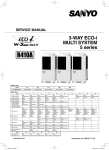
3WAY VRF SYSTEM
U-72MF1U9
U-72MF1U9E *
U-96MF1U9
U-96MF1U9E *
1
TENTATIVE
2
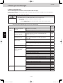
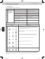
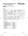
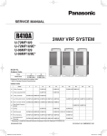
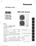
Model No.
Outdoor Units
Class
Model Name
72
U-72MF1U9
U-72MF1U9E*
96
U-96MF1U9
U-96MF1U9E*
3
Refrigerant R410A is used in the outdoor units.
* Salt-Air Damage Resistant Specifications.
Indoor Units
Class
7
9
12
15
18
U1 4-Way Cassette
S-12MU1U6
S-18MU1U6
Y1 4-Way Cassette 60×60
S-12MY1U6
S-18MY1U6
D1 1-Way Cassette
S-07MD1U6 S-09MD1U6 S-12MD1U6
F1 Low Silhouette Ducted
S-07MF1U6 S-09MF1U6 S-12MF1U6 S-15MF1U6 S-18MF1U6
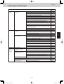
19
24
36
48
54
S-24MU1U6 S-36MU1U6
4
S-24MF1U6 S-36MF1U6 S-48MF1U6 S-54MF1U6
5
M1 Slim Low Static Ducted S-07MM1U6 S-09MM1U6 S-12MM1U6 S-15MM1U6 S-18MM1U6
E1
High Static Pressure
Ducted
T1 Ceiling
S-36ME1U6 S-48ME1U6
S-12MT1U6
S-18MT1U6
S-24MT1U6
S-07MK1U6 S-09MK1U6 S-12MK1U6
P1 Floor Standing
S-07MP1U6 S-09MP1U6 S-12MP1U6 S-15MP1U6 S-18MP1U6
S-24MP1U6
S-07MR1U6 S-09MR1U6 S-12MR1U6 S-15MR1U6 S-18MR1U6
S-24MR1U6
R1
Concealed Floor
Standing
6
S-18MK1U6 S-19MS1U6** S-24MK1U6
K1 Wall Mounted
7
** Necessary to install the External Electronic Expansion Valve Kit (Optional:CZ-P56SVK1U).
85464849302000
REFERENCE NO. SM830202-00
8
SM830202-00_3WAY VRF.indb i
2012/01/30 16:50:37
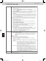
IMPORTANT!
Please Read Before Starting
When Installing…
This air conditioning system meets strict safety and operating standards. As the installer or service person, it is an
important part of your job to install or service the system so
it operates safely and efficiently.
…In a Room
Properly insulate any tubing run inside a room to prevent
“sweating” that can cause dripping and water damage to
walls and floors.
For safe installation and trouble-free operation, you must:
• Carefully read this instruction booklet before beginning.
• Follow each installation or repair step exactly as shown.
• Observe all local, state, and national electrical codes.
• Pay close attention to all warning and caution notices
given in this manual.
This symbol refers to a hazard or
unsafe practice which can result
WARNING
in severe personal injury or death.
CAUTION
…In Moist or Uneven Locations
Use a raised concrete pad or concrete blocks to provide a
solid, level foundation for the outdoor unit. This prevents
water damage and abnormal vibration.
… In an Area with High Winds
Securely anchor the outdoor unit down with bolts and a
metal frame. Provide a suitable air baffle.
…In a Snowy Area (for Heat Pump-type Systems)
Install the outdoor unit on a raised platform that is higher
than drifting snow. Provide snow vents.
This symbol refers to a hazard or
unsafe practice which can result
in personal injury or product or
property damage.
When Connecting Refrigerant Tubing
If Necessary, Get Help
• Ventilate the room well, in the event that is refrigerant
gas leaks during the installation. Be careful not to allow
contact of the refrigerant gas with a flame as this will
cause the generation of poisonous gas.
These instructions are all you need for most installation
sites and maintenance conditions. If you require help for a
special problem, contact our sales/service outlet or your
certified dealer for additional instructions.
• Keep all tubing runs as short as possible.
In Case of Improper Installation
• Use the flare method for connecting tubing.
The manufacturer shall in no way be responsible for
improper installation or maintenance service, including failure to follow the instructions in this document.
• Apply refrigerant lubricant to the matching surfaces of
the flare and union tubes before connecting them, then
tighten the nut with a torque wrench for a leak-free connection.
SPECIAL PRECAUTIONS
WARNING
• Check carefully for leaks before starting the test run.
When Wiring
When Servicing
ELECTRICAL SHOCK CAN CAUSE
SEVERE PERSONAL INJURY OR DEATH.
ONLY A QUALIFIED, EXPERIENCED
ELECTRICIAN SHOULD ATTEMPT TO
WIRE THIS SYSTEM.
• Turn the power OFF at the main power box (mains)
before opening the unit to check or repair electrical parts
and wiring.
• Do not supply power to the unit until all wiring and tubing
are completed or reconnected and checked.
• Clean up the site after you finish, remembering to check
that no metal scraps or bits of wiring have been left
inside the unit being serviced.
• Keep your fingers and clothing away from any moving
parts.
• Highly dangerous electrical voltages are used in this system. Carefully refer to the wiring diagram and these
instructions when wiring. Improper connections and inadequate grounding can cause accidental injury or death.
CAUTION
• Ground the unit following local electrical codes.
• Ventilate any enclosed areas when installing or testing
the refrigeration system. Escaped refrigerant gas, on
contact with fire or heat, can produce dangerously toxic
gas.
• Connect all wiring tightly. Loose wiring may cause overheating at connection points and a possible fire hazard.
When Transporting
• Confirm after installation that no refrigerant gas is leaking. If the gas comes in contact with a burning stove,
gas water heater, electric room heater or other heat
source, it can cause the generation of poisonous gas.
Be careful when picking up and moving the indoor and outdoor
units. Get a partner to help, and bend your knees when lifting
to reduce strain on your back. Sharp edges or thin aluminum
fins on the air conditioner can cut your fingers.
i
SM830202-00_3WAY VRF.indb ii
2012/01/30 14:52:29
Check of Density Limit
The room in which the air conditioner is to be
installed requires a design that in the event of refrigerant gas leaking out, its density will not exceed a set
limit.
The refrigerant (R410A), which is used in the airconditioner, is safe, without the toxicity or combustibility of ammonia,
and is not restricted by laws imposed to protect the ozone
layer. However, since it contains more than air, it poses the
risk of suffocation if its density should rise excessively. Suffocation from leakage of refrigerant is almost non-existent.
With the recent increase in the number of high density
buildings, however, the installation of multi air conditioner
systems is on the increase because of the need fo reffective use off loor space, individual control, energy conservation by curtailing heat and carrying power, etc.
Most importantly, the multi air conditioner system is able
to replenish a large amount of refrigerant compared to
conventional individual air conditioners. If a single unit of
the multi air conditioner system is to be installed in a
small room, select a suitable model and installation procedure so that if the refrigerant accidentally leaks out, its
density does not reach the limit (and in the event of an
emergency, measures can be made before injury can
occur).
ASHRAE and the International Mechanical Code of the
ICC as well as CSA provide guidance and define safeguards related to the use of refrigerants, all of which define
a Refrigerant Concentration Level (RCL) of 25 pounds
per 1,000 cubic feet for R410A refrigerant.
For additional guidance and precautions related to
refrigerant safety, please refer to the following documents:
International Mechanical Code 2009 (IMC-2009)
(or more recently revised)
ASHRAE 15
ASHRAE 34
ii
SM830202-00_3WAY VRF.indb iii
2012/01/30 14:52:29
Contents
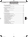
Section 1: TEST RUN ..............................................................................................................1-1
1. Test Run ...........................................................................................................1-2
2. Setting of Unit Control PCB .............................................................................1-4
3. Auto Address Setting .......................................................................................1-6
4. Remote Controller Test Run Settings .............................................................1-12
5. Caution for Pump Down .................................................................................1-13
6. Meaning of Alarm Messages .........................................................................1-14
Section 2: REMOTE CONTROL FUNCTIONS ........................................................................2-1
1. Main Operating Functions ................................................................................2-2
2. Wireless Remote Controller .............................................................................2-4
3. Timer Remote Controller................................................................................2-15
Section 3: TROUBLE DIAGNOSIS .........................................................................................3-1
1. Contents of Remote Controller Switch Alarm Display......................................3-2
2. Outdoor Unit Control PCB LED Display ...........................................................3-4
3. W-3WAY VRF Alarm Codes .............................................................................3-5
4. Blinking (Inspection) Display on the Remote Controller ............................3-26
Section 4: PCB AND FUNCTIONS .........................................................................................4-1
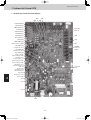
1. Outdoor Unit Control PCB................................................................................4-2
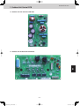
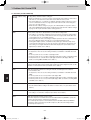
2. Indoor Unit Control PCB ..................................................................................4-7
Section 5: SELF-DIAGNOSIS FUNCTION TABLE .................................................................5-1
1. Self-Diagnosis Function Table..........................................................................5-2
Section 6: SERVICE CHECKER .............................................................................................6-1
1. Outdoor Unit Maintenance Remote Controller .................................................6-2
iii
SM830202-00_3WAY VRF.indb iv
2012/01/30 14:52:29
Contents
TENTATIVE
Test Run
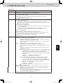
1. TEST RUN
1. Test Run ...............................................................................................................................1-2
1-1. Preparing for Test Run...................................................................................................1-2
1-2. Test Run Procedure .......................................................................................................1-3
2. Setting of Unit Control PCB ...............................................................................................1-4
2-1. Main Outdoor Unit PCB Setting.....................................................................................1-4
3. Auto Address Setting .........................................................................................................1-6
3-1. Auto Address Setting.....................................................................................................1-6
4. Remote Controller Test Run Settings .............................................................................1-12
5. Caution for Pump Down ...................................................................................................1-13
6. Meaning of Alarm Messages ...........................................................................................1-14
1
2
3
4
5
6
7
1-1
8
SM830202-00_3WAY VRF.indb 1
2012/01/30 14:52:29
Test Run
1. Test Run
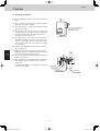
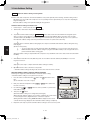
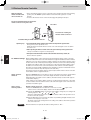
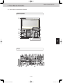
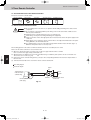
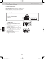
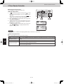
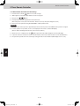
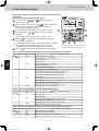
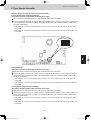
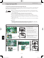
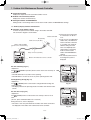
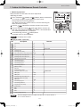
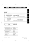
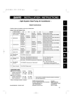
1-1. Preparing for Test Run
z Before attempting to start the air conditioner, check the following.
(1) All loose matter is removed from the cabinet, especially
steel filings, bits of wire, and clips.
ON
(2) The control wiring is correctly connected and all electrical
connections are tight.
(Power must be turned ON
at least 5 hours before
attempting test run)
(3) The protective spacers for the compressor used for transportation have been removed. If not, remove them now.
(4) The transportation pads for the indoor fan have been
removed. If not, remove them now.
Power mains switch
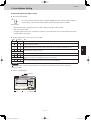
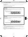
(5) The power has been connected to the unit for at least 5
hours before starting the compressor. The bottom of the
compressor should be warm to the touch and the crankcase heater around the feet of the compressor should be
hot to the touch.
(6) Both the gas and liquid tube service valves are open. If
not, open them now.
1
2
(7) Request that the customer be present for the trial run.
Explain the contents of the instruction manual, then have
the customer actually operate the system.
(8) Be sure to give the instruction manual and warranty certificate to the customer.
(9) When replacing the control PCB, be sure to make all the
same settings on the new PCB as were in use before
replacement.
The existing EEP ROM is not changed, and is connected
to the new control PCB.
Balance tube
Liquid tube
Discharge tube
Suction tube
3
4
5
6
7
1-2
8
SM830202-00_3WAY VRF.indb 2
2012/01/30 14:52:30
Test Run
1. Test Run
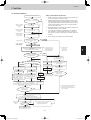
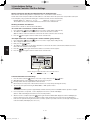
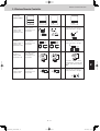
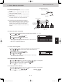
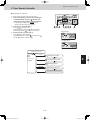
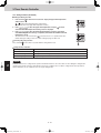
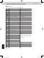
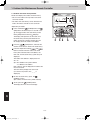
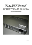
1-2. Test Run Procedure
Items to Check Before the Test Run
Recheck the items to check before the test run.
NO
Have the outdoor sub units been connected?
1.
Turn the remote power switch on at least 5 hours before the test,
in order to energize the crankcase heater.
2.
After performing the leak inspection, applying vacuum, and performing refrigerant charge for the tubing which is connected onsite, fully open the outdoor unit service valve. However if only one
outdoor unit is installed, a balance tube is not used. Therefore,
leave the valve fully closed.
3.
When replacing the control PCB, be sure that the settings on the
new PCB match those on the old PCB.
4.
Use caution when making the settings. If there are duplicated
system addresses, or if the settings for the Nos. of the indoor
units are not consistent, an alarm will occur and the system will
not start.
5.
These settings are not made on the indoor unit PCB.
YES
*1
<Outdoor unit control PCB>
Unit No. setting switch
(S007)
Set the unit address.
<Outdoor unit control PCB>
Unit No. setting switch
(S006)
Set the No. of outdoor units.
<Outdoor unit control PCB>
Unit No. setting switch
(S004 and S005)
Set the No. of indoor units.
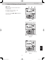
NO
Are the inter-unit control wires
connected to more than 1 refrigerant
system?
(Check the link wiring.)
CASE 1
YES
<Outdoor unit control PCB>
Unit No. setting switch
(S002 and S003)
Set the system address.
When multiple outdoor main units exist, disconnect the terminals
extended from the shorted plugs (CN003) at all outdoor main unit
PCBs except for 1.
Alternatively, move the sockets to the OPEN side.
YES
Is it possible to turn ON the power only
for the 1 refrigerant system where the
test run will be performed?
Note: It is not necessary to remove
the socket that is used to shortcircuit the terminal plugs from
the outdoor sub unit PCBs.
Turn ON the indoor and
outdoor unit power for that
refrigerant system only.
Will automatic address setting be
performed in Heating mode?
YES
CASE 3B
Is it OK to start the compressors?
Make necessary corrections.
CASE 3A
Is it OK to start the compressors?
Turn ON the indoor and
outdoor unit power.
Short-circuit the mode change pin
(CN101) on the outdoor main unit PCB.
At the same time, short-circuit the
automatic address pin (CN100) for 1
second or longer, then release it.
NO
Make necessary
corrections
Short-circuit the automatic address
pin (CN100) on the outdoor main
unit PCB for 1 second or longer,
then release it.
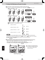
1
Refer to "Table of SelfDiagnostic Functions and
Description of Alarm Displays."
Turn OFF the indoor
and outdoor unit
2
Short-circuit the automatic address pin (CN100)
on the outdoor main unit PCB for 1 second or
longer, then release it.
Check the alarm contents.
*2
*3
Turn OFF the indoor and
outdoor unit power.
Turn ON the indoor and
outdoor unit power.
*2
The unit with the unit
No. set to 1 is the
main unit. All other
units are sub units.
CASE 2
NO
NO
*1
LED 1 and 2 blink alternately
(about 2 or 3 minutes).
3
Are LED 1 and 2 on the
outdoor unit PCB OFF?
YES
4
*3
Start indoor and outdoor unit
cooling operation.
LED 1 and 2 blink alternately.
Start indoor and outdoor unit
heating operation.
LED 1 and 2 blink alternately.
Check the alarm
contents.
NO
Are LED 1 and 2 on the
outdoor unit PCB OFF?
*2
A minimum of 5 hours must have passed after the
power was turned ON to the outdoor unit.
*3
All indoor units operate in all refrigerant systems
where the power is ON.
5
YES
6
Check that test run preparation is OK.
(Do not allow the short-circuited pins to remain short-circuited.)
Set the wired remote controller for test run.
Refer to the remote
controller test-run
settings.
Does system operate?
NO
Check and make corrections according to
"Table of Self-Diagnostic Functions."
7
YES
Return remote control to normal mode
End test run.
1-3
8
SM830202-00_3WAY VRF.indb 3
2012/01/30 14:52:30
Test Run
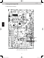
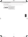
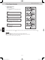
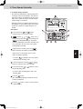
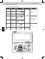
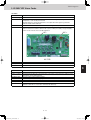
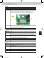
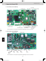
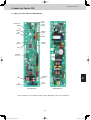
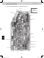
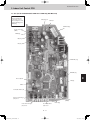
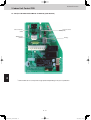
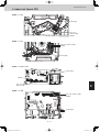
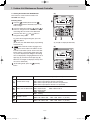
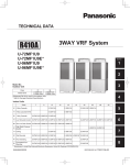
2. Setting of Unit Control PCB
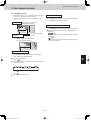
2-1. Main Outdoor Unit PCB Setting
1
2
3
4
CN003
CN101
CN100
5
6
7
S007 S006 S005 S004 S002 S003
1-4
8
SM830202-00_3WAY VRF.indb 4
2012/01/30 14:52:30
Test Run
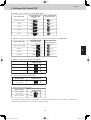
2. Setting of Unit Control PCB
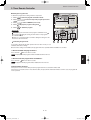
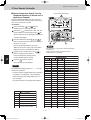
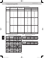
z Examples of the No. of indoor units settings (S005, S004)
No. of indoor units
Indoor unit setting (S005)
(3P DIP switch, blue)
10 20 30
1 unit (factory setting)
All OFF
ON
ON
1
2
3
OFF
ON
2
3
OFF
ON
11 units
Set to 1
1
Set to 1
2 ON
1
2
3
OFF
ON
ON
1
Set to 1
3 ON
1
2
3
OFF
ON
ON
40 units
Set to 1
1
ON
ON
31 units
1
1 ON
1
21 units
Indoor unit setting (S004)
(Rotary switch, red)
0
1 & 3 ON
1
2
3
Set to 0
OFF
z Examples of refrigerant circuit (R.C.) address settings (required when link wiring is used) (S003, S002)
System address No.
System 1 (factory setting)
System address (S003)
(2P DIP switch, blue)
10 20
ON
ON
1 2
ON
OFF
ON
2
ON
OFF
ON
1 2
ON
OFF
ON
2
OFF
1
Both OFF
1
1 ON
System 11
1
System 21
System 30
System address (S002)
(Rotary switch, black)
Set to 1
Set to 1
1
1
Set to 1
2 ON
0
1 & 2 ON
1
Set to 0
2
z Examples of the No. of outdoor units settings (S006)
No. of outdoor units
Outdoor unit setting (S006)
(3P DIP switch, blue)
1 unit (factory setting)
1 ON
ON
ON
1
2
3
OFF
ON
2
3
OFF
ON
2
3
OFF
ON
2 units
1
ON
3 units
3
2 ON
1 & 2 ON
1
z Address setting of main outdoor unit (S007)
Unit No. setting
4
Address setting of outdoor unit (S007)
(3P DIP switch, blue)
ON
ON
Unit No. 1 (main unit)
(factory setting)
1
2
3
OFF
5
z Address setting of sub outdoor unit
Unit No. setting
Unit No. 2 (sub unit)
(factory setting)
Address setting of outdoor unit (S007)
(3P DIP switch, blue)
ON
ON
2 ON
1
2
3
OFF
ON
ON
Unit No. 3 (sub unit)
6
1 & 2 ON
1
2
3
OFF
The sub unit control PCB contains the same switches as the main unit control PCB for No. of indoor units, No. of outdoor units,
and system address. However it is not necessary to set these switches.
7
1-5
8
SM830202-00_3WAY VRF.indb 5
2012/01/30 14:52:32
Test Run
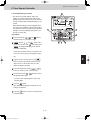
3. Auto Address Setting
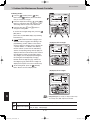
3-1. Auto Address Setting
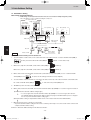
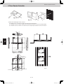
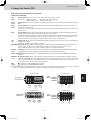
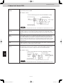
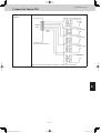
Basic wiring diagram: Example (1)
• If link wiring is not used (The inter-unit control wires are not connected to multiple refrigerant systems.)
Indoor unit addresses can be set without operating the compressors.
No. 1 (main outdoor unit)
settings No. of indoor units
(10 units setting)
System address
(system 1 setting)
(S002)
1
(S003)
ON
1
(S004)
0
ON
2
(S005)
ON
1
No. of
outdoor
units (3 units
setting)
(S006)
ON
1
2
ON
3 OFF
Outdoor Unit
2
3
OFF
Unit number (S007)
ON
setting
(Unit No. 1) 1 2 3
Unit
number
setting
(Unit No. 2)
ON
OFF
Leave the socket that
is used to short-circuit
the terminal plug.
(CN003)
Unit
No. 1
(Main)
No. 3 (sub unit)
No. 2 (sub unit)
ON
OFF
(S007)
ON
1
2
OFF
3
Unit
No. 2
(Sub)
Outdoor main/sub
control wiring
Unit
number
setting
(Unit No. 3)
ON
(S007)
ON
ON
1
2
3
OFF
Unit
No. 3
(Sub)
Outdoor main/sub
control wiring
Inter-unit control wiring
1-1
Indoor Unit
1
1-2
1-3
Remote controller
cross-over wiring
Remote controller
Case 1
1-10
(1) Automatic Address Setting from the Outdoor Unit
2
1.
To set the number of outdoor units, on the outdoor main unit control PCB set the No. of outdoor units DIP switch (S006) to
ON
ON
ON
(3 units), and set the unit No. DIP switch (S007) to
1
2
3
(unit No. 1 - main outdoor unit).
1
OFF
2
3
ON
2.
(unit No. 2).
On the No. 2 (sub) unit control PCB, set the unit No. switch (S007) to
1
3
2
3
ON
3.
(unit No. 3).
On the outdoor main unit control PCB, check that the system address rotary switch (S002) is set to “1” and that the DIP
ON
ON
switch (S003) is set to
4
“0.” (These are the settings at the time of factory shipment.)
1
4.
2
OFF
To set the number of indoor units that are connected to the outdoor unit to 10, on the outdoor main unit control PCB set the
ON
ON
No. of indoor units DIP switch (S005) to
“1.” and set the rotary switch (S004) to “0.”
1
2
3
OFF
5.
Turn ON the power to the indoor and outdoor units.
6.
On the outdoor main unit control PCB, short-circuit the automatic address pin (CN100) for 1 second or longer, then release it.
(Communication for automatic address setting begins.)
* To cancel, again short-circuit the automatic address pin (CN100) for 1 second or longer, then release it.
The LED that indicates that automatic address setting is in progress turns OFF and the process is stopped.
Be sure to perform automatic address setting again.
(Automatic address setting is completed when LEDs 1 and 2 on the outdoor main unit control PCB turn OFF.)
6
7.
7
3
On the No. 3 (sub) unit control PCB, set the unit No. switch (S007) to
1
5
2
Operation from the remote controllers is now possible.
* To perform automatic address setting from the remote controller, perform steps 1 to 5, then use the remote controller and
complete automatic address setting.
z Refer to “Automatic Address Setting from the Remote Controller.”
1-6
8
SM830202-00_3WAY VRF.indb 6
2012/01/30 14:52:32
Test Run
3. Auto Address Setting
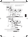
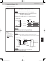
Basic wiring diagram: Example (2)
* When multiple outdoor main units exist, remove the socket that is
used to short-circuit the terminal plug (CN003) from all outdoor
main unit PCBs except for one unit.
Alternatively, move the sockets to the “OPEN” side.
• If link wiring is used
No. 1 (main outdoor unit) settings
No. of indoor units
(13 units setting)
System address
(system 1 setting)
(S002)
1
(S004)
(S003)
ON
ON
2
1
OFF
(S005)
ON
2
1
No. of
outdoor units
(3 units
setting)
(S006)
ON
1
2
3
ON
3
Unit
ON number
setting
OFF (unit No. 1)
No. 2 (sub unit)
OFF
(S007)
ON
1
2
OFF
3
(S007)
ON
1
Leave the socket that
is used to short-circuit
the terminal plug.
(CN003)
Unit
No. 1
(Main)
Outdoor unit
system 1
Unit
number
setting
(unit No. 2)
ON
2
3
No. 3 (sub unit)
Unit
number
setting
(unit No. 3)
ON
OFF
Unit
No. 2
(Sub)
(S007)
ON
1
2
ON
3
OFF
Unit
No. 3
(Sub)
Outdoor main/sub
control wiring
Inter-unit control wiring
1-1
Indoor unit
1-2
1-3
1
Remote controller
communication wiring
Remote
controller
No. 2
Refrigerant
circuit
1-13
No. 1 (main unit) settings
System address
(system 2 setting)
(S002)
No. of indoor units
(9 units setting)
9
ON
ON
2
(S004)
(S003)
2
1
2
OFF
(S005)
ON
1
No. of
outdoor
units (2 units
setting)
(S006)
ON
1
2 3
2
3
Unit
ON number
setting
OFF (unit No. 1)
Outdoor unit
system 2
ON
No. 2 (sub unit) settings
OFF
(S007)
ON
1
Unit
No. 1
(Main)
2
3
Unit
number
setting
(unit No. 2)
ON
OFF
Move the socket to
the “OPEN” side
(CN003).
(S007)
ON
1
2
ON
3
OFF
3
Unit
No. 2
(Sub)
Outdoor main/sub control wiring
4
Inter-unit control wiring
To other system
link wiring
Indoor unit
2-1
2-2
2-9
5
Remote controller
cross-over wiring
Remote
controller
Make settings as appropriate for the cases listed below.
(Refer to the instructions on the following pages.)
· Indoor and outdoor unit power can be turned ON for each system separately.
Case 2
· Indoor and outdoor unit power cannot be turned ON for each system separately.
Automatic address setting in Heating mode
Case 3A
Automatic address setting in Cooling mode
Case 3B
6
7
1-7
8
SM830202-00_3WAY VRF.indb 7
2012/01/30 14:52:33
Test Run
3. Auto Address Setting
Case 2 Automatic Address Setting (no compressor operation)
z Indoor and outdoor unit power can be turned ON for each system separately.
Indoor unit addresses can be set without operating the compressors.
Automatic Address Setting from Outdoor Unit
ON
1.
(unit No. 1).
On the No. 1 (main) unit control PCB, set the unit No. switch (S007) to
1
2
3
ON
On the No. 2 (sub) unit control PCB, set the unit No. switch (S007) to
(unit No. 2).
1
On the No. 3 (sub) unit control PCB, set the unit No. switch (S007) to
3
2
3
ON
1
2.
2
(unit No. 3).
To set the number of outdoor units on the outdoor main unit control PCB, set the No. of outdoor units DIP switch (S006) to
ON
ON
(3 units).
1
3.
2
3
OFF
On the outdoor main unit control PCB, check that the system address rotary switch (S002) is set to “1” and that the DIP
ON
ON
1
switch (S003) is set to “0”
. (These are the settings at the time of factory shipment.)
1
4.
2
OFF
To set the number of indoor units that are connected to the outdoor unit to 13, on the outdoor main unit control PCB set the
ON
ON
2
3
, and set the rotary switch (S004) to “3.”
No. of indoor units DIP switch (S005) to “1”
1
2
3
OFF
5.
Turn on power to all indoor and outdoor units in the system.
6.
Short-circuit the automatic address pin at the outdoor main unit (CN100) for 1 second or longer, then release it.
(Communication for automatic address setting begins.)
* To cancel, again short-circuit the automatic address pin (CN100) for 1 second or longer, then release it.
The LED that indicates automatic address setting is in progress turns OFF and the process is stopped.
Be sure to perform automatic address setting again.
4
5
6
(Automatic address setting is completed when LEDs 1 and 2 on the outdoor main unit control PCB turn OFF.)
7.
Next turn the power ON only for the indoor and outdoor units of the next (different) system. Repeat steps 1 - 5 in the same
way to complete automatic address settings for all systems.
8.
Operation from the remote controllers is now possible.
* To perform automatic address setting from the remote controller, perform steps 1 - 5, then use the remote controller and
complete automatic address setting.
z Refer to “Automatic Address Setting from Remote Controller.”
7
1-8
8
SM830202-00_3WAY VRF.indb 8
2012/01/30 14:52:33
Test Run
3. Auto Address Setting
Case 3A Automatic Address Setting in Heating Mode
z Indoor and outdoor unit power cannot be turned ON for each system separately.
In the following, automatic setting of indoor unit addresses is not possible if the compressors are not operating.
Therefore perform this process only after completing all refrigerant tubing work.
Automatic Address Setting from Outdoor Unit
1.
Perform steps 1 - 4 in the same way as for Case 2 .
5.
Turn the indoor and outdoor unit power ON at all systems.
6.
To perform automatic address setting in Heating mode , on the outdoor main unit control PCB in the refrigerant system
where you wish to set the addresses, short-circuit the automatic address pin (CN100) for 1 second or longer, then release
it. (Be sure to perform this process for one system at a time. Automatic address settings cannot be performed for more than
one system at the same time.)
(Communication for automatic address setting begins, the compressors turn ON, and automatic address setting in Heating
mode begins.)
(All indoor units operate.)
* To cancel, again short-circuit the automatic address pin (CN100) for 1 second or longer, then release it. The
LED that indicates automatic address setting is in progress turns OFF and the process is stopped. Be sure to
perform automatic address setting again.
1
(Automatic address setting is completed when the compressors stop and LED 1 and 2 on the main unit control PCB turn
OFF.)
7.
At the outdoor main unit in the next (different) system, short-circuit the automatic address pin (CN100) for 1 second or
longer, then release it.
2
(Repeat the same steps to complete automatic address setting for all units.)
8.
Operation from the remote controllers is now possible.
* To perform automatic address setting from the remote controller, perform steps 1 - 5, then use the remote controller and
to complete automatic address setting.
3
z Refer to “Automatic Address Setting from Remote Controller.”
4
5
6
7
1-9
8
SM830202-00_3WAY VRF.indb 9
2012/01/30 14:52:34
Test Run
3. Auto Address Setting
Case 3B Automatic Address Setting in Cooling Mode
z Indoor and outdoor unit power cannot be turned ON for each system separately. In the following, automatic setting of indoor
unit addresses is not possible if the compressors are not operating. Therefore perform this process only after completing all
refrigerant tubing work.
Automatic address setting can be performed during Cooling operation.
Automatic Address Setting from Outdoor Unit
1.
Perform steps 1 - 4 in the same way as for Case 2 .
5.
Turn the indoor and outdoor unit power ON at all systems.
6.
To perform automatic address setting in Cooling mode , on the outdoor main unit control PCB in the refrigerant system
where you wish to set the addresses, short-circuit the mode change 2P pin (CN101). At the same time, short-circuit the
automatic address pin (CN100) for 1 second or longer, then release it. (Be sure to perform this process for one system at a
time. Automatic address settings cannot be performed for more than one system at the same time.)
(Communication for automatic address setting begins, the compressors turn ON, and automatic address setting in Cooling
mode begins.)
(All indoor units operate.)
* To cancel, again short-circuit the automatic address pin (CN100) for 1 second or longer, then release it. The
LED that indicates automatic address setting is in progress turns OFF and the process is stopped. Be sure to
perform automatic address setting again.
1
(Automatic address setting is completed when the compressors stop and LED 1 and 2 on the outdoor main unit control PCB
turn OFF.)
2
7.
At the outdoor main unit in the next (different) system, short-circuit the automatic address pin (CN100) for 1 second or
longer, then release it.
(Repeat the same steps to complete automatic address setting for all units.)
3
8.
Operation from the remote controllers is now possible.
* Automatic address setting in Cooling mode cannot be done from the remote controller.
Automatic Address Setting* from the Remote Controller
Selecting each refrigerant system individually for automatic address setting
---Automatic address setting for each system: Item code “A1.”
4
5
1.
button and
Press the remote controller timer time
time.
(Press and hold for 4 seconds or longer.)
button at the same
2.
Next, press either the temperature setting
the item code is “A1.”)
button. (Check that
3.
Use either the
or
matic address setting.
4.
Then press the
or
button to set the system No. to perform auto-
button.
(Automatic address setting for one refrigerant system begins.)
(When automatic address setting for one system is completed, the system returns
to normal stopped status.) <Approximately 4 - 5 minutes is required.>
6
(During automatic address setting, “NOW SETTING” is displayed on the remote
controller. This message disappears when automatic address setting is completed.)
5.
Repeat the same steps to perform automatic address setting for each successive system.
7
1 - 10
8
SM830202-00_3WAY VRF.indb 10
2012/01/30 14:52:34
Test Run
3. Auto Address Setting
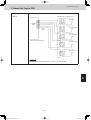
Display during automatic address setting
z On outdoor main unit PCB
LED 2
1
*
Do not short-circuit the automatic address setting pin (CN100) again while automatic address setting is in
progress. Doing so will cancel the setting operation and will cause LED 1 and 2 to turn OFF.
Blink alternately
*
When automatic address setting has been successfully completed, both LED 1 and 2 turn OFF.
*
LED 1 is D72. LED 2 is D75.
*
If automatic address setting is not completed successfully, refer to the table below and correct the problem. Then perform
automatic address setting again.
z Display of LED 1 and 2 on the outdoor unit control PCB
(
: ON
: Blinking
LED1
:OFF)
LED2
Display meaning
After the power is turned ON (and automatic address setting is not in progress), no communication with the indoor
units in that system is possible.
After the power is turned ON (and automatic address setting is not in progress), 1 or more indoor units are
confirmed in that system; however, the number of indoor units does not match the number that was set.
Alternating
1
Automatic address setting is in progress.
Automatic address setting completed.
Simultaneous
Alternating
At time of automatic address setting, the number of indoor units did not match the number that was set.
“ ”(when indoor units are operating) indication appears on the display.
Refer to “Table of Self-Diagnostic Functions and Description of Alarm Displays.”
2
NOTE
“ ” indicates that the solenoid is fused or that there is a CT detection current failure (current is detected when the
compressor is OFF).
3
z Remote controller display
is blinking
4
5
6
7
1 - 11
8
SM830202-00_3WAY VRF.indb 11
2012/01/30 14:52:35
3. Auto Address Setting
4. Remote Controller Test Run Settings
Test Run
Request concerning recording the indoor/outdoor unit combination Nos.
After automatic address setting has been completed, be sure to record them for future reference.
List the outdoor main unit system address and the addresses of the indoor units in that system in an easily visible location (next
to the nameplate), using a permanent marking pen or similar means that cannot be abraded easily.
Example: (Outdoor) 1 - (Indoor) 1-1, 1-2, 1-3…
(Outdoor) 2 - (Indoor) 2-1, 2-2, 2-3…
These numbers are necessary for later maintenance. Please be sure to indicate them.
Checking the indoor unit addresses
Use the remote controller to check the indoor unit address.
<If 1 indoor unit is connected to 1 remote controller>
1.
2.
Press and hold the
button and
button for 4 seconds or longer (simple settings mode).
The address is displayed for the indoor unit that is connected to the remote controller.
(Only the address of the indoor unit that is connected to the remote controller can be checked.)
3.
Press the
button again to return to normal remote controller mode.
<If multiple indoor units are connected to 1 remote controller (group control)>
1
1.
2.
Press and hold the
button and
button for 4 seconds or longer (simple settings mode).
“ALL” is displayed on the remote controller.
3.
4.
Next, press the
button.
The address is displayed for 1 of the indoor units which is connected to the remote controller. Check that the fan of that
indoor unit starts and that air is discharged.
5.
6.
Press the
Press the
button again and check the address of each indoor unit in sequence.
button again to return to normal remote controller mode.
2
3
Number changes to indicate which indoor unit is currently selected.
4
5
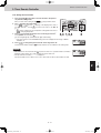
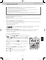
4. Remote Controller Test Run Settings
1.
Press the remote controller
button for 4 seconds or longer. Then press the
button.
“TEST RUN” appears on the LCD display while the test run is in progress.
The temperature cannot be adjusted when in Test Run mode.
(This mode places a heavy load on the machines. Therefore use it only when performing the test run.)
2. The test run can be performed using the HEAT, COOL, or FAN operation modes.
NOTE
The outdoor units will not operate for approximately 3 minutes after the power is turned ON and after operation is stopped.
6
3.
If correct operation is not possible, a code is displayed on the remote controller LCD display.
(Refer to “Table of Self-Diagnostic Functions” and correct the problem.)
4.
After the test run is completed, press the
button again. Check that “TEST RUN” disappears from the LCD display. (To
prevent continuous test runs, this remote controller includes a timer function that cancels the test run after 60 minutes.)
If the test run is performed using the wired remote controller, operation is possible even if the cassette-type ceiling panel has
not been installed. (“P09” display does not occur.)
*
7
1 - 12
8
SM830202-00_3WAY VRF.indb 12
2012/01/30 14:52:35
Test Run
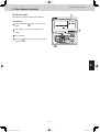
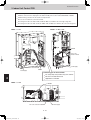
5. Caution for Pump Down
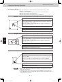
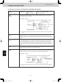
5. Caution for Pump Down
Pump down means refrigerant gas in the system is returned to the outdoor unit. Pump down is used when the unit is to be
moved, or before servicing the refrigerant circuit.
CAUTION
This outdoor unit cannot collect more
than the rated refrigerant amount as
shown by the nameplate on the back.
If the amount of refrigerant is more
than that recommended, do not
conduct pump down. In this case use
another refrigerant collecting system.
1
2
3
4
5
6
7
1 - 13
8
SM830202-00_3WAY VRF.indb 13
2012/01/30 14:52:36
Test Run
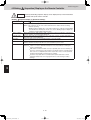
6. Meaning of Alarm Messages
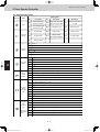
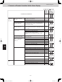
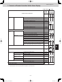
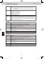
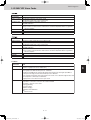
6. Meaning of Alarm Messages
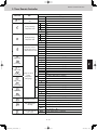
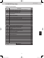
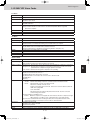
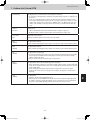
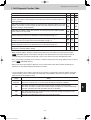
Table of Self-Diagnostics Functions and Description of Alarm Displays
Alarm messages are indicated by the blinking of LED 1 and 2 (D72, D75) on the outdoor unit PCB. They are also displayed on
the wired remote controller.
z Viewing the LED 1 and 2 (D72 and D75) alarm displays
LED1
LED2
Alternating
(
Alarm contents
Alarm Display
LED 1 blinks M times, then LED 2 blinks N times. The cycle then repeats.
M = 2: P alarm 3: H alarm 4: E alarm 5: F alarm 6: L alarm
N = Alarm No.
Example: LED 1 blinks 2 times, then LED 2 blinks 17 times. The cycle then repeats.
Alarm is "P17".
: Blinling) Connect the outdoor maintenance remote controller to the RC socket on the outdoor main unit control PCB (3P,
blue),and check the Alarm Messages on the remote controller display.
Alarm
Message
Possible cause of malfunction
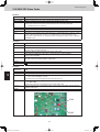
Serial
communication
errors
Mis-setting
Remote controller is
detecting error signal from
indoor unit.
Outdoor unit is detecting error
signal from indoor unit.
2
Error in transmitting serial communication signal.
Indoor unit is detecting error signal from remote controller and system controller.
Indoor unit is detecting error
signal from outdoor unit.
1
Error in receiving serial communication signal.
(Auto address is not completed.)
Improper setting
E04
Error in receiving serial communication signal.
There is an indoor unit which does not send signals when the
power is ON.
E06
Indoor unit address setting is duplicated.
<<E08>>
Duplicated remote controller "main" setting.
<<E09>>
Error of main indoor unit in receiving serial communication signal
from sub indoor units.
E18
During auto. address setting,
number of connected units
does not correspond to
number set.
Number of connected indoor units is less than the number set.
E15
Number of connected indoor units is more than the number set.
E16
No indoor unit is connected.
E20
Main outdoor unit is detecting error signal from sub outdoor unit.
E24
Duplicated outdoor unit address setting.
E25
Mismatch in "No. of outdoor units" setting.
E26
Error of sub outdoor unit in receiving signal from main outdoor unit.
Improper setting
Connected indoor unit is not a multi unit.
Duplication of main indoor unit address setting in group control.
Group control wiring is connected to individual control indoor unit.
5
Indoor unit address is not set.
Capacity code of indoor unit is not set.
Duplication of outdoor system address setting.
Thermistor
fault
E12
Indoor unit communication
error of group control wiring.
4
6
<E02>
<<E03>>
Group wiring failure of indoor units in the refrigerant system
(occurring when remote controller is operated immediately after
automatic address setting)
Starting auto. address setting is prohibited.
AP pin / CN102 is shorted while the auto. address setting started.
3
<E01>
Indoor unit
E29
<<L02>>
<L03>
L07
L08
<<L09>>
L04
Capacity code of outdoor unit is not set.
L10
Mismatch of outdoor unit type.
L17
Indoor coil temp. sensor (E1)
<<F01>>
Indoor coil temp. sensor (E3)
<<F03>>
Indoor suction air (room) temp. sensor (TA)
<<F10>>
Indoor discharge air temp. sensor (BL)
<<F11>>
Continued
7
1 - 14
8
SM830202-00_3WAY VRF.indb 14
2012/01/30 14:52:36
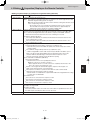
Test Run
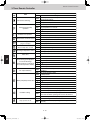
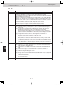
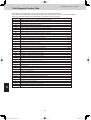
6. Meaning of Alarm Messages
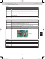
Alarm
Message
Possible cause of malfunction
Activation of
protective
device
Protective device in indoor unit
is activated.
Thermal protector in indoor unit fan motor is activated.
<<P09>>
Float switch is activated.
<<P10>>
Operation of protective function of fan inverter.
P12
O2 sensor (detects low oxygen level) activated.
P14
Incorrect discharge temperature. (Comp. No. 1 (INV))
P03
High pressure switch is activated.
P04
Negtive (defective) phase.
P05
Compressor running failure resulting from missing phase in the
compressor wiring, etc. (Start failure not caused by IPM or no gas.)
P16
Incorrect discharge temperature. (Comp. No. 2 (constant speed))
P17
Outdoor unit fan motor is unusual.
P22
Overcurrent at time of compressor runs more than 80Hz (DCCT
secondary current or ACCT primary current is detected at a time other
than when IPM has tripped.)
P26
IPM trip (IPM current or temperature)
H31
Inverter for compressor is unusual. (DC compressor does not operate.)
Thermistor fault
Indoor thermistor is either open
or damaged.
Outdoor thermistor is either
open or damaged.
P29
Indoor coil temp. sensor (E1)
<<F01>>
Indoor coil temp. sensor (E3)
<<F03>>
Indoor suction air (room) temp. sensor (TA)
<<F10>>
Indoor discharge air temp. sensor (BL)
<<F11>>
Comp. No. 1 (INV) discharge gas temp. sensor (DISCH1)
F04
Comp. No. 2 (constant speed) discharge gas temp. sensor (DISCH2)
F05
Outdoor No. 1 coil gas temp. sensor (EXG1)
F06
Outdoor No. 1 coil liquid temp. sensor (EXL1)
F07
Outdoor air temp. sensor (AIR TEMP)
F08
Compressor suction temp. sensor (SCT)
F12
High pressure sensor.
F16
Low-pressure sensor failure
F17
Outdoor No. 2 coil gas temp. sensor (EXG2)
F23
Outdoor No. 2 coil liquid temp. sensor (EXL2)
EEPROM on indoor unit PCB failure
Protective
device for
compressor is
activated
<<P01>>
Improper wiring connections of ceiling panel.
F24
Protective device for
compressor No.1 (INV) is
activated.
EEPROM on the main or sub outdoor unit PCB has failed.
F31
Current is not detected when comp. No. 1 (INV) is ON.
H03
Protective device for
compressor No.2 (constant
speed) is activated
Overload current is detected.
H11
Lock current is detected.
H12
Current is not detected when comp. No.2 (constant speed) is ON.
H13
Discharge gas temperture of comp. No.2 (constant speed) is not
detected.
H15
Low pressure trouble
H06
Oil sensor fault.
(Disconnection, etc.)
2
3
F29
Low oil level alarm.
1
4
H07
Comp. No.1 (INV) oil sensor
H08
Comp. No.2 (constant speed) oil sensor
H27
5
Continued
6
7
1 - 15
8
SM830202-00_3WAY VRF.indb 15
2012/01/30 14:52:36
Test Run
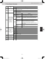
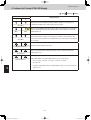
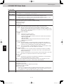
6. Meaning of Alarm Messages
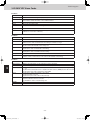
Alarm messages displayed on system controller
Serial
communication
errors
Mis-setting
Activation of
protective
device
Error in transmitting serial
communication signal
Indoor or main outdoor unit is not oparating correctly.
Mis-wiring of control wiring between indoor unit, main outdoor unit and
system controller.
C05
Error in receiving serial
communication signal
Indoor or main outdoor unit is not operating correctly.
Mis-wiring of control wiring between indoor unit, main outdoor unit and
system controller.
CN1 is not connected properly.
C06
Protective device of sub indoor
unit in group control is activated
When using wireless remote controller or system controller, in order to
check the alarm message in detail, connect wired remote controller to
indoor unit temporarily.
P30
NOTE
1.
2.
Alarm messages in << >> do not affect other indoor unit operations.
Alarm messages in < > sometimes affect other indoor unit operations depending on the fault.
1
2
3
4
5
6
7
1 - 16
8
SM830202-00_3WAY VRF.indb 16
2012/01/30 14:52:37
Contents
TENTATIVE
Remote Control Functions
2. REMOTE CONTROL FUNCTIONS
1. Main Operating Functions .................................................................................................2-2
1-1. Room Temperature Control ...........................................................................................2-2
1-2. Automatic Control for Heating and Cooling ...................................................................2-3
2. Wireless Remote Controller ..............................................................................................2-4
2-1. How to Use the Wireless Remote Controller .................................................................2-4
2-2. Receiver ........................................................................................................................2-7
2-3. Operation.......................................................................................................................2-8
2-4. Using the Wireless Remote Control Unit .......................................................................2-9
2-5. Address Settings .........................................................................................................2-10
2-6. Emergency Operation .................................................................................................2-12
2-7. Trouble Diagnosis ........................................................................................................2-14
3. Timer Remote Controller .................................................................................................2-15
3-1. How to Use the Timer Remote Controller....................................................................2-15
3-2. Names and Operations ...............................................................................................2-16
3-3. Installation Manual for Timer Remote Controller .........................................................2-18
3-4. How to Install the Remote Controller...........................................................................2-18
3-5. Group Control Using 2 Remote Controllers.................................................................2-19
3-6. Remote Controller Setting Mode .................................................................................2-19
3-7. Indoor Unit Setting Mode.............................................................................................2-19
3-8. To Display the Sensor Temperature .............................................................................2-19
3-9. To Display the Trouble History .....................................................................................2-19
3-10. Setting the Present Time ...........................................................................................2-21
3-11. Weekly Program Function .........................................................................................2-22
3-12. Outing Function .........................................................................................................2-27
3-13. Sleeping Function......................................................................................................2-29
3-14. Wired Remote Controller Test Run Settings ..............................................................2-30
3-15. Simple Settings Function...........................................................................................2-31
3-16. Detailed Settings Function ........................................................................................2-33
3-17. Remote Controller Servicing Functions.....................................................................2-40
1
2
3
4
5
6
7
2-1
8
SM830202-00_3WAY VRF.indb 1
2012/01/30 14:52:37
Remote Control Functions
1. Main Operating Functions
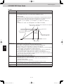
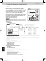
1-1. Room Temperature Control
The thermostat is turned ON/OFF according to
T as shown below.
T = Room temperature - Set temperature
When remote controller sensor
is used
Room temperature = Temperature detected by the remote controller sensor
When body sensor is used
Room temperature = Temperature detected by the body sensor - Intake shift temperature*
* Intake shift temperature (enabled only during heating)
During heating, a difference in temperature occurs between the top and bottom of a room. This value is set in consideration for
the difference between the temperature detected by the body sensor and the temperature at the bottom of the room.
<Value set for intake shift temperature at time of shipment>: 7°F
NOTE
The shift temperature can be selected in the range of 0 – 18°F, by using the remote controller simplified setting mode.
Cooling
Heating
T
T
Room temperature
Room temperature
(deg)
(deg)
1
+2
+4
+2
Set temperature
–2
–4
Set temperature
–2
2
3
Thermostat
ON
OFF
ON
Thermostat
ON
OFF
ON
(1) After the thermostat turns ON, it will not turn OFF again as a result of T for 5 minutes.
(2) After the thermostat turns OFF, it will not turn ON again for 3 minutes. (It also will not turn ON for 3 minutes after the power
is switched ON.)
(3) The compressor turns OFF if the mode is changed cooling
heating (or heating
cooling) while the compressor is ON.
(4) If “test run” mode is selected, the thermostat will not turn OFF as a result of T for 60 minutes. (The thermostat is forced
ON.)
4
5
6
7
2-2
8
SM830202-00_3WAY VRF.indb 2
2012/01/30 14:52:37
Remote Control Functions
1. Main Operating Functions
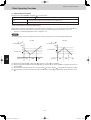
1-2. Automatic Control for Heating and Cooling
Automatic Heating/Cooling Control
(1) When operation starts, heating or cooling is selected according to the set temperature and the room temperature.
Room temperature Set temperature + 2
Cooling
Set temperature – 2 < Room temperature Set temperature + 2
Monitoring mode (*1)
Room temperature < Set temperature – 2
Heating
*1: If the difference between the room temperature and set temperature is small when operation starts, the cooling
thermostat remains in standby status (OFF) until the temperature difference increases. When the temperature difference increases, either cooling operation or heating operation is selected. This standby status is known as “monitoring
mode.”
(2) After operation starts in the selected operating mode, the set temperature is automatically shifted by + 4°F (cooling operation) or – 4°F (heating operation).
Example: Temperature set on the remote controller is 68°F.
Selected operating mode
Shifted set temp.
Remote controller display
1
Cooling
72°F
68°F
2
Heating
64°F
68°F
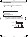
(3) Operating mode changes (heating
cooling, cooling
heating) which occur during operation as a result of temperature
changes are handled as shown below.
Heating
cooling: Room temperature
Shifted set temperature (set temperature + 4°F + 1°F
Cooling
heating: Room temperature
Shifted set temperature (set temperature – 4°F – 2°F
Example: Temperature set on the remote controller is 68°F.
Operating mode change
1
Shifted set temp.
1
Heating
Cooling
68 + 4 + 1 = 73°F or higher (*2)
2
Cooling
Heating
68 – 4 – 2 = 62°F or lower
*2: During heating operation when the body sensor is used, a temperature shift is applied to the intake temperature
detected by the sensor, in consideration for the difference in temperature at the top and bottom of the room. (Refer
cooling change
to the “Room Temperature Control” item.) If this intake shift temperature is 7°F, then the heating
occurs when the temperature detected by the body sensor is 80°F or higher.
(4) Cooling (heating) operation does not change if the room temperature changes from area C
A (or A
C) within 10
minutes after the compressor turns OFF. (Monitoring mode is excepted.)
+6 deg
+5 deg
+4 deg
Selected operating mode
Shifted set temp
2
A
3
B
4
+2 deg
Remote controller display
–2 deg
Shifted set temp
–4 deg
Selected operating mode
–6 deg
C
Thermostat
ON
OFF ON OFF ON
Heating
OFF ON OFF ON OFF ON
Cooling
5
Heating
6
7
2-3
8
SM830202-00_3WAY VRF.indb 3
2012/01/30 14:52:38
Remote Control Functions
2. Wireless Remote Controller
Optional Controller (Remote Controller)
Wireless Remote Controller / CZ-RWSU1U (for X Type) / CZ-RWST1U (for A, T Type) /
CZ-RWSC1U (for U, D Type) / CZ-RWSK1U (for K Type) / CZ-RWSY1U
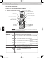
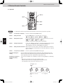
2-1. How to Use the Wireless Remote Controller
B: Transmitter
O: Remote control sensor
A: ON/OFF operation button
C: MODE button
D: Temperature setting buttons
E: FAN SPEED selector button
J: TIMER SET button
I: FLAP bu tton
K: Time setting buttons
G: ADDRESS bu tton
L: SET button
F: FILTER button
M: CL button
1
N: VENTILATION button
P: ACL button
(ALL CLEAR)
H: A/C SENSOR button
Q: Slide switch
2
3
NOTE
The illustration above pictures the wireless remote control unit after the cover
has been lowered and removed.
A: ON/OFF operation button
This button is for turning the air conditioner on and off.
B: Transmitter
When you press the buttons on the wireless remote control unit, the mark appears in the
display to transmit the setting changes to the receiver in the air conditioner.
C: MODE button
Use this button to select one of the following five operating modes.
(AUTO)
4
: Used to automatically set cooling or heating operation. Only for single heat pump
type
(Temperature range: 62 ~ 80°F)
(HEAT)
: Used for normal heating operation. Only for heat pump type
(Temperature range: 60 ~ 78°F)
(DRY)
: Used for dehumidifying without changing the room temperature.
(Temperature range: 64 ~ 86°F)
5
(COOL)
: Used for normal cooling operation.
(Temperature range: 64 ~ 86°F)
(FAN)
6
D: Temperature setting buttons
: Used to run the fan only, without heating or cooling operation.
: Press this button to increase the temperature setting.
: Press this button to decrease the temperature setting.
E: FAN SPEED selector button
(AUTO)
(HI)
7
(MED)
(LO)
: The air conditioner automatically decides the fan speeds.
: High fan speed
: Medium fan speed
: Low fan speed
2-4
Continued
8
SM830202-00_3WAY VRF.indb 4
2012/01/30 14:52:38
Remote Control Functions
2. Wireless Remote Controller
F: FILTER button
If a separately installed signal receiver is being employed, this button is used to turn off its
filter lamp. When the filter lamp has lighted, first clean the filter, and then press the FILTER
button to turn off the filter lamp. When a wired remote control unit and wireless remote
control unit are both used, the filter sign on the wired remote control unit will appear. When
this happens, first clean the filter, and then press the FILTER button on one of the remote
control units to turn off the filter sign.
G: ADDRESS button
When a multiple number of indoor units that can be operated by the wireless remote
control unit have been installed in the same room with a multi-unit or single-unit installation,
this button enables addresses to be set in order to prevent the sending of signals to the
wrong indoor unit. Each of up to six indoor units can be controlled separately using its own
wireless remote control unit by matching the number of the address switch on the operation
area of the indoor unit and the number used for the address of its remote control unit. (The
indoor units cannot be controlled separately when they are used in a flexible combination
format, simultaneous operation of multi units format or any other such format since they will
all operate at the same time.)
NOTE
H: A/C SENSOR button
NOTE
I: FLAP button
When the batteries are replaced, the address setting returns to "ALL", so you must make
the setting again.
When you press this button (use a narrow-tipped object such as a ballpoint pen), the
indication will disappear on the display. The room temperature is detected by the sensor
which is built into the indoor unit and the air conditioner is controlled accordingly.
If the remote control is located near a heat source, such as a space heater or in direct
sunlight, press the A/C SENSOR button to switch to the sensor on the indoor unit.
1. Use this button to set the airflow direction to a specific angle.
The airflow direction is displayed on the remote control unit.
Cooling mode:
Heating mode:
CAUTION
NOTE
1
Number of airflow direction settings
3
5
Operation mode
(COOL) or (DRY)
(HEAT) or (FAN)
(AUTO)
3
5
2
In the Cool mode and Dry mode, if the flaps are set in a downward
position, condensation may form and drip around the vent.
Do not move the flap with your hands.
This function is available only for models X, XM, A, T and K.
3
(SWEEP) 2. Use this button to make the airflow direction sweep up and down automatically.
Press this button several times until the
symbol appears on the display.
To stop the swing operation
Press the FLAP button again during the flap swing operation to stop the flap at the desired
position. Then, the airflow can be set from the top position by pressing the FLAP button
again.
4
5
6
7
2-5
8
SM830202-00_3WAY VRF.indb 5
2012/01/30 14:52:39
Remote Control Functions
2. Wireless Remote Controller
Indicator when swing operation is stopped
Fan and heating
Cooling and drying
During cooling and drying, the flap does not stop at the downward position.
Even if the flap is stopped at the downward position during the swing operation, it does not
stop until it moves to the third position from the top.
NOTE
J: TIMER SET button
This function is available only for models X, XM, A, T and K.
Use this button while the unit is operating to switch between timer settings.
(OFF Timer)
: The air conditioner stops after a preset time elapses.
: The air conditioner always stops after a preset time elapses.
: The air conditioner starts after a preset time elapses.
(OFF Cycle Timer)
(ON Timer)
K: Time setting buttons
L: SET button
Use this button to set the timer.
M: CL button
Use this button to clear the timer setting.
N: VENTILATION button
This is used when a ventilation fan (available commercially) is connected. Pressing the
VENTILATION button turns the fan on and off. The ventilation fan also turns on and off when
the air conditioner unit is turned on and off. (The display of the remote control unit shows
" " while the ventilation fan is running.)
* If the VENTILATION button is held down for 4 or more seconds when the batteries have
been replaced, " " appears on the display, and the ventilation fan can be used.
O: Remote control sensor
This detects the temperature around the remote control unit when the remote control unit
position has been selected using the sensor button.
P: ACL button (ALL CLEAR)
Puts the wireless remote control unit into pre-operation status. This is used after the batteries have been replaced or when the slide switch setting has been changed.
Q: Slide switch
This switch is for setting the operation mode of the indoor unit and setting the flaps.
1
2
: Press this button to increase the time.
: Press this button to decrease the time.
3
4
NOTE
The wireless remote control unit sends the temperature signal to the air
conditioner regularly at five-minute intervals. If the signal from the wireless
remote control unit stops for more than ten minutes due to the loss of the
wireless remote control unit or other trouble, the air conditioner will switch to
the temperature sensor which is built into the indoor unit and control the room
temperature. In these cases, the temperature around the wireless remote
control unit may differ from the temperature detected at the air conditioner's
position.
When low fan speed is selected and the air conditioner is in cooling operation at a low outdoor temperature of less than 50°F, the air conditioner may
automatically switch to medium fan speed to prevent freezing.
5
6
7
2-6
8
SM830202-00_3WAY VRF.indb 6
2012/01/30 14:52:39
Remote Control Functions
2. Wireless Remote Controller
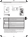
2-2. Receiver
The signal receivers with the exception of the separately installed signal receiver are mounted on the indoor units.
X, XM types
A, T types
Separately installed
signal receiver
(U, D types)
K type
1
A: Receiver
This section picks up infrared signals from the wireless remote control unit (transmitter).
Indication lamps
One of these lamps will blink when trouble has occurred. When an indicator lamp starts to
blink, refer to “Trouble Diagnosis” on page 2-14.
B: Operation lamp
This lamp lights when the appliance is turned on.
C: Timer lamp
This lamp lights when the system is being controlled by the timer.
D: Standby lamp
• This lamp lights at the following times during heating operations:
When operation has started, when the thermostat has been activated, during defrosting
operation.
• The lamp blinks when trouble has occurred.
E: Emergency operation
button
This is used when operation cannot be performed due to trouble with or loss of the wireless
remote control unit.
F: ADDRESS switch
This switch is used in order to prevent the sending of signals to the wrong indoor unit when
a multiple number of indoor units that can be operated by the wireless remote control units
have been installed in the same room.
G: SWING button
When this button is pressed, the airflow sweeps up and down automatically.
H: FILTER lamp
This lamp lights to indicate that it is time to clean the filter.
2
3
4
5
• If two beeps are heard, the operation lamp among the indication lamps has lighted and the timer lamp and standby
lamp blink alternately. In cases where heat pump models are used, this indicates a Cooling/Heating mode mismatch
and, as such, operation in the desired mode cannot be performed.
(The same beeps will be heard and the same operation lamps will light when auto cooling/heating has been selected
on a model which does not have the auto cooling/heating function.)
• When local operation has been set to disable because the centralized control mode is established, for instance,
pressing the ON/OFF operation button, MODE button or temperature setting buttons results in the sounding of
five beeps, and the attempted change in the operation will not be accepted.
6
7
2-7
8
SM830202-00_3WAY VRF.indb 7
2012/01/30 14:52:40
Remote Control Functions
2. Wireless Remote Controller
2-3. Operation
STEP 1, 6
STEP 2
STEP 4
STEP 5
STEP 3
NOTE
1
• To warm up the system, the power mains must be turned on at least five (5) hours before operation.
STEP 1
To start the air conditioner:
Press the operation button (ON/OFF button).
STEP 2
Setting the mode:
Press the MODE button to select the mode of your choice.
[
(AUTO),
(HEAT),
(DRY),
(COOL) or
(FAN) ]
STEP 3
Setting the fan speed:
Press the FAN SPEED selector button to select the fan speed of your choice.
[
(AUTO),
(HI.),
(MED.) or
(LO.) ]
2
3
4
If AUTO is selected, the fan speed switches automatically.
STEP 4
Setting the temperature:
Use the
or
button as appropriate to change the temperature setting as desired.
(
reduces the temperature, and
increases the temperature. )
* The temperature cannot be set during FAN mode operation.
STEP 5
Setting the airflow direction: When more than one indoor unit is connected, the UNIT button is used first to
select a unit. Then use the FLAP button to set the airflow direction to a specific
angle or to sweep.
STEP 6
To stop the air conditioner:
Press the operation button (ON/OFF button) again.
Automatic heating and
cooling
The air conditioner automatically performs heating and cooling operation based on the
difference between the temperature setting and room temperature. All indoor units in the
same refrigerant system can be operated with a single group control.
Simultaneous operation of
multiple units (Group
control)
Group control is suitable for air conditioning of a large room using multiple air conditioning
units.
• One remote control unit can control up to eight indoor units.
• All indoor units have the same settings except for the airflow direction.
• The temperature sensors at the indoor unit side are used.
5
Outdoor unit
6
Indoor unit
7
Remote control unit
Signal line
2-8
8
SM830202-00_3WAY VRF.indb 8
2012/01/30 14:52:40
Remote Control Functions
2. Wireless Remote Controller
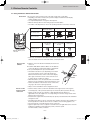
2-4. Using the Wireless Remote Control Unit
Slide switch
This is used to set the operation mode of the indoor units and to set the flaps.
• Depending on the indoor unit used, the operation display and airflow direction display
settings will differ as shown below.
• Use a pointed implement to change the switch position.
• When the switch position has been changed, press the ACL button.
* For details on the flap functions, refer to the operating instructions of the indoor unit used.
Model which supports
different flap settings
Swing-only model
Heat pump (with auto
cooling/heating
function)
Heat pump (without
auto cooling/heating
function)
No-flap model
Slide switch position
Flap display on wireless
remote control unit
With the battery cover
removed
How to install
batteries
Operation mode display
on wireless remote
control unit
1
Slide switch position
• Before use, check that the slide switch has been set to the position shown in the figure
above. For details on how to set the slide switch, consult your dealer.
2
1. Slide the cover in the direction indicated by the arrow and
remove it.
2. Install two AAA alkaline batteries. Make sure the batteries
point in the direction marked in the battery compartment.
3. Use a pointed implement to press the ACL button.
3
• The batteries last about a year, depending on how much
you use the wireless remote control unit. Replace the
batteries when the wireless remote control unit's display
fails to light, or when the remote control cannot be used
to change the air conditioner's settings.
• When the batteries are to be replaced, make sure that both
batteries are new and that the same kind of battery is used.
• Remove the batteries if the wireless remote control unit is
not going to be used for a prolonged period.
• Dispose of the used batteries at the designated location.
How to use the
wireless remote
control unit
Cooling only
ACL
button
Cover
• Point the wireless remote control unit's transmitter at the signal receiver. If the signal is
received properly, a beep is heard. (Two beeps are heard only when operation starts up.)
• Signals can be received over a distance of approximately 26 ft. This distance is
approximate: it may be slightly more or less depending on how much charge remains in the
batteries and on other factors.
• Ensure that the signals will not be blocked by any objects positioned between the transmitter
and signal receiver.
• Avoid placing the wireless remote control unit where it will be exposed to direct sunlight or in
the direct path of the air blown out from the air conditioner, near a heating appliance, etc.
• Do not drop, throw or wash the wireless remote control unit.
• Signal reception may not be accepted in rooms with fluorescent lights that use the electronic
instantaneous lighting system (rapid start system) or inverter system.
For further details, contact your dealer.
4
5
6
7
2-9
8
SM830202-00_3WAY VRF.indb 9
2012/01/30 14:52:40
Remote Control Functions
2. Wireless Remote Controller
When mounting the
wireless remote control
unit on a wall for use
• Before mounting the wireless remote control unit on the wall, place the unit at the mounting
position, press the ON/OFF operation button and check that the signals are received
properly.
• To remove the wireless remote control unit, disengage it by pulling it toward you.
Secure the installation fitting of the wireless
remote control unit using the screws.
1
Press.
Place here.
Procedure for installing the
wireless remote control unit
2
Installation fitting of wireless remote control unit
Operating tips
1
• Do not operate the wireless remote control unit too far away from the signal receiver.
Doing so may cause operational errors.
Make absolutely sure that the wireless remote control unit and signal receiver are both in
the same room.
• When operating the wireless remote control unit, point it directly at the signal receiver.
A beep is heard when a signal is received properly.
• Avoid places where the wireless remote control unit will be obscured by curtains, etc.
Remove it before operation.
2
2-5. Address Settings When a multiple number of indoor units that can be operated by the wireless remote control unit
have been installed in the same room with a multi-unit or single-unit installation, this button enables
addresses to be set in order to prevent the sending of signals to the wrong indoor unit. Each of up to
six indoor units can be controlled separately using its own wireless remote control unit by matching
the number of the address switch on the operation area of the indoor unit and the number used for
the address of its wireless remote control unit. (The indoor units cannot be controlled separately
when they are used in a flexible combination format, simultaneous operation of multi units format or
any other such format since they will all operate at the same time.)
The signal receiver has an address switch for signal reception, and the wireless remote control unit
has an address switch for signal transmission.
3
4
5
How to check the
addresses
When the ADDRESS button on the wireless remote control unit is pressed, the current address
appears on the wireless remote control unit's display. The buzzer sounds if the address
displayed matches the signal receiver's address. (The buzzer always sounds if “ALL” appears
as the address display.)
If “ALL” appears as the address display, operations can be performed irrespective of the signal
receiver's address. Point the wireless remote control unit at the signal receiver of the unit to be
operated, and send the signal.
How to set the
matching address
Wireless remote control unit̉s address setting
1. When the ADDRESS button is held down for 4 or more seconds, “
” lights on the
wireless remote control unit's display, and the current address blinks.
2. Each time the ADDRESS button is now pressed, the address changes by one setting in the
following sequence: ALL
1
2
3
6
ALL.
Select the setting which matches the setting of the address switch in the operation area of
the indoor unit to be operated.
3. When the SET button is now pressed, the address stops blinking and lights instead, and it
remains on the display for 5 seconds.
The buzzer sounds if the setting matches the setting of the address switch in the operation
area of the indoor unit.
6
7
NOTE
When the batteries are replaced, the address setting returns to “ALL ”.
2 - 10
8
SM830202-00_3WAY VRF.indb 10
2012/01/30 14:52:41
Remote Control Functions
2. Wireless Remote Controller
Wireless remote
control unit
address displays
……
X type
Position of
address switch on
signal receiver
(inside indoor unit)
* The address switch
in the operation
area may be set to
any position.
A, T types
Position of
address switch on
signal receiver
(inside indoor unit)
* The address switch
in the operation
area may be set to
any position.
K type
Position of
address switch
inside indoor unit
* The address switch
in the operation
area may be set to
any position.
For positions 1, 2 and 3, set the
knob to the left; conversely, for 4, 5
and 6, set the knob to the right.
……
For positions 1, 2 and 3, set the
knob to the left; conversely, for 4, 5
and 6, set the knob to the right.
……
1
……
For positions 1, 2 and 3,set the
knob upward (1); conversely, for 4,
5 and 6, set the knob downward
(ON).
U, D types
Position of
address switch in
signal receiver
2
For positions 1, 2 and 3, set the
knob to the left; conversely, for 4, 5
and 6, set the knob to the right.
* The address switch
in the operation
area may be set to
any position.
……
3
* Wireless remote control unit for XM type does not have the function of address switch.
4
5
6
7
2 - 11
8
SM830202-00_3WAY VRF.indb 11
2012/01/30 14:52:41
Remote Control Functions
2. Wireless Remote Controller
2-6. Emergency Operation
In any of the following events, use the Emergency operation button to operate the air
conditioner on a makeshift basis.
• When there is no charge remaining in the wireless remote control unit's batteries
• When the wireless remote control unit has failed
• When the wireless remote control unit has been lost or misplaced
X, XM types
Initiate operation using the Emergency operation button in the operation area of the indoor unit.
Operation
Press the Emergency operation button.
The air conditioner initiates a cooling operation when its operation is started up at
a room temperature of 75°F or above.
Conversely, it initiates a heating operation when its operation is started up at a
room temperature below 75°F.
Shutdown
Press the Emergency operation button once more.
1
A, T types
Initiate operation using the Emergency operation button in the signal receiver on the indoor unit.
Operation
Press the Emergency operation button.
The air conditioner initiates a cooling operation when its operation is started up at
a room temperature of 75°F or above.
Conversely, it initiates a heating operation when its operation is started up at a
room temperature below 75°F.
2
Shutdown
3
Press the Emergency operation button once more.
K type
4
Initiate operation using the Emergency operation button in the operation area of the indoor unit.
Operation
Set the ON/OFF operation switch to “OFF” first.
Then set it to “ON. ”
If a heat pump is used, the air conditioner initiates a cooling operation when its
operation is started up at a room temperature of 75°F or above or it initiates
a heating operation when its operation is started up at a room temperature below
75°F.
5
Shutdown
6
Set the ON/OFF operation switch to “OFF.”
NOTE
7
• TEST is used to initiate a trial run when the air conditioner is first installed. It is not used
under normal circumstances.
• To restart the wireless remote control unit's operation, the ON/OFF operation switch must
be set to ON without fail. If it is kept at the OFF setting, the signals from the wireless remote
control unit will not be accepted.
2 - 12
8
SM830202-00_3WAY VRF.indb 12
2012/01/30 14:52:41
Remote Control Functions
2. Wireless Remote Controller
U, D types
Initiate operation using the Emergency operation button in the signal receiver.
1. Press the Emergency operation button.
The air conditioner initiates a cooling operation when its operation is started
up at a room temperature of 75°F or above.
Conversely, it initiates a heating operation when its operation is started up at a
room temperature below 75°F.
2. When the SWING button is pressed, the air direction is automatically switched
from upward to downward or vice versa.
Shutdown
Press the Emergency operation button once more.
1
2
3
4
5
6
7
2 - 13
8
SM830202-00_3WAY VRF.indb 13
2012/01/30 14:52:41
Remote Control Functions
2. Wireless Remote Controller
2-7. Trouble Diagnosis
Check out the following points before requesting service.
Trouble
Possible Cause
Check again.
The air conditioner
does not run even
when the ON/OFF
operation switch has
been set to ON.
1
Is the air conditioner in the shutdown mode or
was the switch operated after a power failure?
Press the wireless remote control unit's
ON/OFF operation button again.
How about the local power switch?
If it was off, set it now to on.
Have any of the fuses blown?
If a fuse has blown, contact your dealer.
Is the ON timer operation mode established?
Clear the timer operation.
If the signal receiver's NORMAL/ALL OFF
switch set to “ALL OFF”?
If it is, set it to the “NORMAL” position and
cancel the operation.
Have the wireless remote control unit's
batteries run down?
If they have, replace them with new ones.
Do the indication lamps show a cooling/heating
mismatch or is the auto cooling/heating
function not available?
Change the operation mode.
Auto cooling/heating or heating appears on the display even though the air
conditioner is a cooling-only model.
Trouble
Contact your dealer.
• Some kind of trouble has occurred in communication between the signal
receiver and indoor unit. Alternatively, the wrong address has been set
when a wired remote control unit is used.
Operation
Timer
Preparing for
operation
Operation
Timer
Preparing for
operation
• Some kind of trouble has occurred in communication between the indoor
unit and outdoor unit.
Operation
Timer
Preparing for
operation
• The indoor unit's protection device has been activated. Alternatively, the
auto flap connector of the ceiling panel has been disconnected.
Operation
Timer
Preparing for
operation
• The outdoor unit's protection device has been activated.
Operation
Timer
Preparing for
operation
• Something is wrong with the temperature sensor.
Operation
Timer
Preparing for
operation
• The outdoor unit's compressor has been protected.
Operation
Timer
Preparing for
operation
• A trial run mode is underway. Set the trial run mode to Off.
2
4
Change the setting of the wireless remote
control unit's slide switch. (See page 2-9)
Possible Cause
(An indicator lamp is blinking.)
3
Remedy
5
6
7
If the trouble persists even after performing the checks recommended above, shut down the air conditioner's operation, set the
local power switch to OFF, and contact your dealer with the model number and trouble symptoms. You must NOT attempt to
make repairs yourself due to the dangers involved. If one or more of the indication lamps is blinking, give this information to the
dealer as well.
2 - 14
8
SM830202-00_3WAY VRF.indb 14
2012/01/30 14:52:42
Remote Control Functions
3. Timer Remote Controller
3-1. How to Use the Timer Remote Controller
Operating buttons
13
1
2
3
12
11
10
9
1
4
5
6
7
8
2
3
Display
1
2 34
5 6 7 8 9 10 31 11 12
13
4
5
30 28 27 25
29 26
23 22
24
21
18 17 16 15 14
20
6
7
2 - 15
8
SM830202-00_3WAY VRF.indb 15
2012/01/30 14:52:42
Remote Control Functions
3. Timer Remote Controller
3-2. Names and Operations
Operation Section
1.
Start/Stop button
Pushing this button starts, and pushing again stops the
unit.
2.
Operation lamp
The lamp is turned on when an air conditioner is in operation.
This lamp blinks when an error occurs or a protective
device is activated.
3.
Mode Select button
Pushing this button to select an operation mode. (AUTO
/HEAT /DRY /COOL /FAN ).
4.
Temperature setting buttons
Changing the temperature setting.
5.
FAN speed button
Changing the fan speed.
6.
Swing/Air direction button *1
Use this button to set the auto swing or air direction to a
specific angle.
7.
Unit Select button
When more than one indoor unit is operated by one remote control unit, this button is used to select a unit when
adjusting the air direction.
8.
Timer setting buttons
Weekly Program Function)
(
9.
FILTER reset button
Use this button to reset the filter sign.
When is displayed, press this button after cleaning the
filter.
1
2
(Refer to the previous page)
10.
Ventilation button
Use this button when you installed a fan available in the
market. Pressing this button turns on and off the fan.
When turning off the air conditioner, the fan will be also
turned off.
(While the fan is operating,
will appear in the display.)
*If
is displayed on the LCD of the remote control unit
when pressing the ventilation button, no fans are installed.
11.
Inspection button
Do not use this button.
12.
(
Sleeping button
Sleeping Function)
13. Remote control sensor
Normally, the temperature sensor of the indoor unit is
used to detect the temperature. However, it is also possible to detect the temperature around the remote control
unit.
*1 Do not move the flap (vertical airflow adjustment board)
with your hand.
The flap is automatically directed down when the unit is
stopped.
The flap is directed up during the HEAT standby. The
flap starts swinging after the HEAT standby is cancelled, although the AUTO flap indication on the remote
control unit is displayed during the HEAT standby.
3
4
5
6
7
2 - 16
8
SM830202-00_3WAY VRF.indb 16
2012/01/30 14:52:42
Remote Control Functions
3. Timer Remote Controller
Display Section
(Refer to the page 2-15)
1.
SETTING indication
Appears when the timer program is being set.
2.
UNIT indication
Indicates the unit No. of the indoor unit which is selected
with the Unit Select button, or the unit in which an abnormality occurs.
3.
TIMER No. indication
Appears when the time program is being set.
4.
17.
Operation mode change control indication
Displays when an operation mode is entered by the remote control unit, while another operation mode has been
already selected. This indicates that the operation mode
cannot be changed.
18.
Disabled Feature indication
Displayed if the selected feature was disabled during
installation.
Timer program
: The indoor unit starts operation at the programmed
time.
: The indoor unit stops operation at the programmed
time.
20.
Heating standby mode indication
appears when the fan of the indoor unit is stopped or in
low fan speed.
21.
/
/
/ Fan mode select indication
The selected fan mode is displayed.
5.
Today’s day of the week
Indicates today’s day of the week.
22.
SWING indication
Appears while the flap swings.
6.
Program schedule indication
Appears under days that are scheduled for program operation.
23.
Flap position indication
Indicates the flap position.
24.
7.
Present time
Displays the present time on a 24-hour clock. Also, displays settings in the various setting modes.
Filter indication
Appears when filter needs cleaning. Clean the filter.
25.
Inspection indication
Appears when the protective device is activated or when
an abnormality occurs.
26.
Ventilation indication
Appears when a fan available in the market is installed
and is operating.
27.
Oil indication
Appears when the engine oil needs to be changed. (Appears when the gas heat pump air conditioner is used.)
8.
TIMER OFF indication
Displayed when the timer has been turned OFF.
9.
ERROR indication
Displayed when a mistake is made during timer setting.
10.
Outing indication (
Outing function)
Appears when the outing function is set.
11. Upper and lower limit indication of the outing function
: Indicates the upper limit of the temperature
: Indicates the lower limit of the temperature
12. Operation Mode indication
Displays the selected operation mode. (AUTO
/DRY /COOL /FAN ).
28.
Sleeping
Appears during the sleeping function.
29.
CAUTION
Appears when the protective device is activated or when
an abnormality occurs.
/HEAT
13. Temperature indication
Indicates the set temperature.
30. Unit No. indication
Indicates the unit No. of the selected indoor unit.
31.
14. °F / °C temperature unit indication
1
2
3
TEST indication
Appears while in test operation.
15.
Remote control sensor indication
Appears when the remote control sensor is used.
4
16.
Centralized control indication
Appears when operated in centralized control. If the
remote control operation is not permitted to the remote
unit, when the Start/Stop button, Mode Select button or
flashes and
Temperature setting button is pressed,
rejects the change.
5
6
7
2 - 17
8
SM830202-00_3WAY VRF.indb 17
2012/01/30 14:52:43
Remote Control Functions
3. Timer Remote Controller
3-3. Installation Manual for Timer Remote Controller
Accessories for remote controller switch
Remote controller
Wood screws
Wire joints
Operation manual
Installation manual
(with 8 in.
wire)
3-4. How to install the Remote Controller
CAUTION
1
2
Do not supply power to the unit or try to operate it until the tubing and wiring to the outdoor unit is
completed.
Do not twist the control wiring with the power wiring or run it in the same metal conduit, because
this may cause malfunction.
Install the remote controller away from sources of electrical noise.
Install wiring correctly(incorrect wiring will damage the equipment).
Install a noise filter or take other appropriate action if electrical noise affects the power supply circuit
of the unit.
When wiring, do not connect the remote controller wires to the adjacent terminal block for the power
wiring. Otherwise, the unit will break down.
Use shielded wires for remote control wiring and ground the shield on indoor unit sides. (Fig. 2-1)
Otherwise misoperation due to noise may occur.
The mounting position for the remote controller should be located in an accessible place for control.
Never cover the remote controller or recess it into the wall.
(1) When you open the decorative cover (Fig. 2-4), you will see 2 gaps under the remote controller.
Insert a coin into these gaps and pry off the back case.
(2) Attach the back case with the 2 wood screws provided. Using a screwdriver, push open the cut-outs on the back case.
These holes are for screws. (Fig. 2-5)
(3) Connect the remote controller wiring (2 wires) correctly to the corresponding terminals in the electrical component box of
the indoor unit.
(4) To finish, fit the back tabs of the case into the remote controller and mount it.
Basic Wiring Diagram
Connection diagram
3
Approx.
8 in.
Terminal board for
indoor unit remote
controller wiring
4
W
1
BK
2
1
2
Shielded wire
Ground
Connector
Remote controller wiring
(field supply)
Remote
controller
unit
Power wire from remote
controller unit
Fig. 2-1
5
6
7
2 - 18
8
SM830202-00_3WAY VRF.indb 18
2012/01/30 14:52:44
Remote Control Functions
3. Timer Remote Controller
Use AWG#20 to AWG#16 wires.
Remote controller wiring can be extended to a maximum
of 1640 ft.
(1) Strip the insulation to approximately 35/64" from the ends
of the wires that will be connected.
(2) Twist together the 2 wires and create a crimp connection
at the wire joint.
(3) If a special crimping tool is not used, or if the connection
is soldered, insulate the wires using insulation tape.
Provided wire joint (white)
Remote controller wiring
Power wire from remote
controller unit
Wire joint
Fig. 2-2
Remote controller
(main)
3-5. Group Control Using 2 Remote Controllers
12
It does not matter which of the 2 remote controllers you
set as the main controller. When using multiple remote
controllers (up to 2 can be used), one serves as the
main remote controller and the other as the sub-remote
controller.
(sub)
Connection wiring
for group control 1 2
2P terminal
base for remote
control wiring
12
Indoor unit
No. 1
12
12
Indoor unit
Indoor unit
No. 3
No. 2
12
Indoor unit
No. 8
: Ground (earth)
Fig. 2-3
3-6. Remote Controller Setting Mode
To set the remote controller main/sub setting or change the sensor, follow the steps below.
and
buttons on the remote controller for more than
Press both
4 seconds together.
CODE
ITEM
buttons.
Select CODE No. with
ITEM
Change DATA with
(TIMER) buttons.
RCU. Main/Sub
. Finally, press
.
Press
Clock display
* DATA is memorized in the RCU. (DATA setting will not be changed even
RCU. CK
when the power is turned off.)
Room temperature sensor
* Make sure to set [Normal] for RCU. CK.
1
DATA
Sub
Main
24 hours 12 hours (AM/PM)
RCU. CK
Normal
Main unit
RCU
2
3
3-7. Indoor Unit Setting Mode
To select the ventilation setting or change the temperature unit, follow the steps below.
+
+
buttons on the remote controller for more than 4 secPress
onds together.
CODE
buttons.
Select CODE No. with
ITEM
Change DATA with
(TIMER) buttons.
. Finally, press
.
Press
* DATA is memorized in the indoor unit. (DATA setting will not be changed
even when the power is turned off.)
DATA
ITEM
Vent. button
Temperature unit
3-8. To Display the Sensor Temperature:
Press both
and
buttons on the remote controller for more than 4 seconds together.
buttons.
Change the sensor address (CODE No.) with
button.
Select the UNIT No. which you want to call with the
Press the
button to finish service mode.
No
o
C
Yes
o
F
4
5
6
3-9. To Display the Trouble History:
Press both
and
buttons on the remote controller for more than 4 seconds together.
buttons
Change the alarm message:
CODE No.
button to finish service mode.
Press the
(New) (Old)
7
2 - 19
8
SM830202-00_3WAY VRF.indb 19
2012/01/30 14:52:44
Remote Control Functions
3. Timer Remote Controller
Fig. 2-4
Fig. 2-5
1/8
Caution when installing the remote controller
*1 Install the remote controller more than 3-3/8" apart from the wall surface.
*2 To install the remote controllers side-by-side, keep the space between each for more than 4-59/64".
*3 To install the remote controllers one above the other, keep the space between each for more than 1".
3/16
1
4-3/4
2
3
4-3/4
4
5/8
1-1/2
1
1
1/16
5
3/16 × 3/8
3/16 × 7/16
4-9/16
3-5/16
1-3/4
6
3/16 × 3/8
13/16
1
unit :in.
11/64 × 3/8
4-7/16
7
2 - 20
8
SM830202-00_3WAY VRF.indb 20
2012/01/30 14:52:45
Remote Control Functions
3. Timer Remote Controller
3-10. Setting the Present Time
1.
Press and hold
for more than 2 seconds to enter in the present
day and time setting mode.
, “ ”(day) and “time” flash.
Once you enter in the setting mode,
2.
Set “ ” to today’s day of the week.
Press
*1
to move “ ” (flashing on the display) in the order of :
Su
Mo
Tu
.... Press
to move it in the order of : Su
St
Fr
....
*1
While in time setting mode, the temperature setting buttons function as
(changing day) button.
3.
to change the present “hour” in the range of 0 to 23*2.
Press
Set the present hour and press .
The “hour” digits light up, and the “minute” digits start flashing.
*2
If the clock uses the 12 hours AM/PM setting, the hour is displayed in the range of AM 0 to
11/PM 0 to 11.
4.
, to change the present “minute” in the range of 0 to 59.
Press
Set the present minute and press . The day and time are set and finishes the setting mode.
3,4 1,3,4
2
NOTE
• The unit returns to the normal mode if
is pressed or there is no operation made for 3 minutes
during the setting. In this case, all the settings in progress will be lost.
• If the present time is invalid, “– – : – –” is displayed.
If the power failure for more than 1 hour occurs, check if the set data of day and time are valid.
1
2
3
4
5
6
7
2 - 21
8
SM830202-00_3WAY VRF.indb 21
2012/01/30 14:52:45
Remote Control Functions
3. Timer Remote Controller
3-11. Weekly Program Function
Checking Weekly Timer
Set the weekly program assigning a given timer to each day of the week.
Maximum of 6 programs a day and 42 programs a week can be set.
Select the day and the TIMER number you want to program.
Program image diagram
button
Vertical scale indicates the TIMER No.,
and horizontal scale indicates the day.
* If the day is changed, the TIMER No.
returns to “1”.
1
1.
to enter the program confirmation mode
Press
“ ” and start setting.
Once you enter the program confirmation mode, the
present day is indicated as TIMER No. “1”.
2.
Select the day.
and
/
to move the “ ” horizonPress
tally on the day to select.
to move “ ” (flashing on the display) in the
Press
order of : Su
Mo
Tu....
Press
to move it in the order of : Su
Sa
Fr....
“– – : – –” is displayed when the program is not set.
2
3.
TIMER No.
Su Mo Tu We Th Fr Sa
1
2
3
4
5
6
1
Select a section from
the 42 programs.
3
program CHeck
Select a Timer number.
/
to select a TIMER No. from 1 to 6.
Press
Press
to move up from 1.
Press
to move down from 6.
2
TIMER No. 1~6
3
4
5
6
7
2 - 22
8
SM830202-00_3WAY VRF.indb 22
2012/01/30 14:52:46
Remote Control Functions
3. Timer Remote Controller
Changing the Program Timer
To set the weekly program, follow the steps below.
1.
Select the program you want to set in the program
confirmation mode, and press . The enters the
setting mode of the program currently displayed.
, “hour”,
* In the program setting mode,
“minute” and “item” flash on the display.
2.
Set the “hour”. (program step 1)
/
to set the “hour”.
Press
Confirm the “hour” and press . The enters the pro(setting of the “minute”).
gram changing mode
3.
Set the “minute”. (program step 2)
/
to set the “minute”.
Press
Confirm the “minute” and press .The unit enters
(the program pattern selection mode).
2,3,4 1,2,3,4 4
Program step1
Program step2
1
normal remote controller
PROGRAM
CANCEL
SET
Changing hour digits
CANCEL,DEL
program check
Program
CANCEL,DEL
SET
Changing minute digits
2
SET
SET,CANCEL,DEL
Changing patterns
PROGRAM
Selecting copy source
CANCEL
SET
3
Selecting copy destination
SET,CANCEL
4
5
6
7
2 - 23
8
SM830202-00_3WAY VRF.indb 23
2012/01/30 14:52:46
Remote Control Functions
3. Timer Remote Controller
4. Set the program pattern.
(program step 3)
Pattern 1
There are 4 program patterns.
Pressing
/
repeats the following display patterns.
Pattern 1
The indoor unit starts operation at the programmed
time.
Pattern 2
Pattern 2
The indoor unit stops operation at the programmed
time.
Pattern 3
Pattern 3
The indoor unit starts operation at the programmed
time and changes the temperature settings.
Press
/
to change the temperature setting.
Pattern 4
Pattern 4
1
The indoor unit changes the temperature setting at
the programmed time.
Press
2
/
to change the temperature setting.
Select the program pattern and press
. The program timer setting is confirmed and the unit enters the confirmation mode
.
NOTE
3
If you press
during the setting, it returns to the program confirmation mode.
If there is no operation made for 3 minutes during the setting, it returns to the normal mode.
In this case, all the settings in progress will be invalid.
4
5
6
7
2 - 24
8
SM830202-00_3WAY VRF.indb 24
2012/01/30 14:52:47
Remote Control Functions
3. Timer Remote Controller
Deleting the Program Timer
To delete the program timer setting, follow the steps below.
1.
Press
to enter the program confirmation mode.
2.
Press
delete.
/
to select the day of the program you want to
3.
Press
/
4.
Press
to display the program setting mode
to select a TIMER No. (from 1 to 6).
5.
Press
.
to delete the program.
NOTE
After deleting, the unit returns to the program confirmation mode .
If you press
during the setting, the unit returns to the program
confirmation mode.
If there is no operation made for 3 minutes during the setting, the unit
returns to the normal mode.
5 3 4
Invalidating Program Timer
1
2
If you want to adjourn the program operation for more than 1 week, you can
invalidate all the timer settings.
Once the timer settings are invalidated, the program will not be operated until the invalidation is cancelled.
1
<<How to invalidate the program timer>>
Press and hold
for more than 2 seconds.
is displayed and the programs will be invalidated from the next one.
2
<<How to cancel the program timer invalidation>>
Press and hold
for more than 2 seconds.
disappears and the programs will be validated from the next one.
If Power Failure Occurred
If the power recovers in a short time period, the program after the recovered time will be valid.
If the power recovered more than 1 hour after the failure, the present time information will be lost. In this case, the program will
not be operated.
3
4
5
6
7
2 - 25
8
SM830202-00_3WAY VRF.indb 25
2012/01/30 14:52:47
Remote Control Functions
3. Timer Remote Controller
Duplicating the Program Timer
You can duplicate the preset program by day.
Select the copy source.
1.
2.
3.
4.
If
is pressed in program checking mode , it enters
the copy mode (Selecting the copy source ) of the program timer.
While in the copy mode of the program timer,
and
(day) of the copy source flash on the display.
Press
/
to select the day of the copy source.
Select the copy destination.
is pressed in the mode of selecting the copy source
If
, it enters the copy mode (Selecting the copy destination ) of the program timer.
Press
/
to select the day of the copy source.
to complete copying and return to the
Then, press
program checking mode.
1
3,5
2,4
NOTE
The program will be overwritten if the preprogrammed day is selected as a copy source.
1
Before Asking Repair Work
Before asking repair work, please check the followings.
Trouble
Possible Cause/Remedy
“ERROR” is displayed when the If there is another TIMER No. which has the program of the same time and same day, you cannot overlap the
minute digits are entered.
setting.
The set data is not stored.
2
Program does not function.
The stored programs are automatically sorted by the time. Check if the data is stored in the other TIMER No.
Check if the time indication is not “– – : – –”.
When the time is invalid, the program is also invalid.
Check the remote controller prohibition inside.
In that case, the program is invalid.
3
4
5
6
7
2 - 26
8
SM830202-00_3WAY VRF.indb 26
2012/01/30 14:52:48
Remote Control Functions
3. Timer Remote Controller
3-12. Outing Function
Outing function is a function that prevents the room temperature from increasing too much (or decreasing too much) when no
one is in the room.
An air conditioner works automatically if this function is set effective.
General Performance of the Outing Function
COOL / DRY
The air conditioner starts operation when the room temperature increases up to –1°F of the upper limit.
The air conditioner stops operation when the room temperature decreases up to –2°F of the upper limit.
For Example
Setting at Outing Temperature 86°F.
Outing function Upper limit
(Setting at Outing Temperature)
86°F
(ON)
1°F
85°F
2°F
Room temperature
84°F
(OFF)
1
HEAT
The air conditioner starts operation when the room temperature decreases up to +1°F of the lower limit.
The air conditioner stops operation when the room temperature increases up to +2°F of the lower limit
For Example
Setting at Outing Temperature 53°F.
2
(OFF)
Room temperature
55°F
2°F
Outing function Lower limit
1°F
(ON)
3
56°F
53°F
(Setting at Outing Temperature)
4
[Precautions]
The outing control only starts/stops the air conditioner. It does not change the operation mode/temperature setting.
Therefore, the operation mode/temperature needs to be set beforehand so that the outing function turns on the air conditioner with your desired operation mode/ temperature setting.
If the room temperature rapidly changes, the room temperature may get over the upper or lower limit when the outing function is activated.
The outing function is invalid during FAN/AUTO operation mode.
The air conditioner's stop order (stated in /above) is valid only when the outing function is operated.
If operated using other remote control unit (or a centralized control device such as a system control), the outing function does
not work.
5
6
7
2 - 27
8
SM830202-00_3WAY VRF.indb 27
2012/01/30 14:52:48
Remote Control Functions
3. Timer Remote Controller
3-12. Outing Function (Continued)
Setting the Outing Function
1.
Press and hold
for more than 2 seconds to display the upper limit temperature
setting screen.
,
and the upper limit temperature start flashing.
(The default value of the upper limit temperature is 99°F.)
2.
/
to select the upper limit temperature and press
Press
value. The lower limit temperature setting screen is displayed.
3.
/
to select the lower limit temperature, and press
to fix the
Press
value. The outing function setting is completed. (The default value of the lower limit
temperature is 50°F.)
The unit returns to the normal mode if
is pressed or there is no operation made for 3
minutes during the setting. In this case, all the settings in progress will be lost.
*
to fix the
2
Canceling the outing function
for more than 2 seconds while the outing function is set.
Press and hold
3
Outing function indication
Outing function indication
Off
1
Status
The outing function is not set.
Flashing
The outing function is now being set, or under operation.
Lighting
Although the outing function is set, not under operation.
NOTE
2
A remote controller loses outing function operation information when it is cut for more than one hour during the outing function
operation by electricity. It reverts from the blackout, and an air conditioner does not drive in outing function when operation is
started. At this time, an air conditioner does not stop at outing function.
3
4
5
6
7
2 - 28
8
SM830202-00_3WAY VRF.indb 28
2012/01/30 14:52:49
Remote Control Functions
3. Timer Remote Controller
3-13. Sleeping Function
*
*
This function leads you to a comfortable sleep and changes the room temperature during your sleep.
You can set the off timer every one hour from 1 to 10
hours.
When the off time comes:
The indoor unit stops.
* The temperature returns to the setting at the time when
sleeping function operation started.
Operating time Display of remote control unit
(during the time setting)
Sleeping function
indication
To cancel the sleeping function operation:
Press
.
* The temperature setting remains at the time cancelled.
The following buttons also cancel the sleeping function
operation.
button
Stop the indoor unit after the sleeping function operation
is cancelled.
button
Changes the operation mode after the sleeping function
operation is cancelled.
Off time In case the present time
is 23:00.
Display of remote control unit (during sleeping function setting)
1
Sleeping function indication
*
If no operation is made for 3 minutes, the time setting
mode will be automatically finished.
Ex. In case of 7 hours timer
.
1. Press
Each time the button is pressed, the indication changes in
the following order.
3
(every one hour)
(Press
2.
2
to stop the time setting.)
Press .
The sleeping operation starts.
4
5
6
7
2 - 29
8
SM830202-00_3WAY VRF.indb 29
2012/01/30 14:52:49
Remote Control Functions
3. Timer Remote Controller
3-14. Wired Remote Controller Test Run Settings
1. Press the remote controller
button for 4 seconds or longer.
2. “TEST” appears on the LCD display while the test run is in progress.
3. Then press the
●
button.
The temperature cannot be adjusted when in Test Run mode.
(This mode places a heavy load on the machines. Therefore use it only when performing the test run.)
●
The test run can be performed using the HEAT, COOL, or FAN operation modes.
NOTE
The outdoor units will not operate for approximately 3 minutes after the power is turned ON and after operation is stopped.
●
If correct operation is not possible, an error code is displayed on the remote controller LCD display.
(Refer to “Table of Self-Diagnostic Functions” and correct the problem.)
4. After the test run is completed, press the
button again. Check that “TEST” disappears from the LCD display.
●
To prevent continuous test runs, this remote controller includes a timer function that cancels the test run after 60 minutes.
●
The operation is possible even if the cassette-type ceiling panel has not been installed. (“P09” display does not occur.)
1
2
3
4
5
6
7
2 - 30
8
SM830202-00_3WAY VRF.indb 30
2012/01/30 14:52:49
Remote Control Functions
3. Timer Remote Controller
3-15. Simple Settings Function
• This allows the filter lifetime, operating mode priority change, central control address, and other settings to be made for an individual or group-control
indoor unit to which the remote controller used for
simple settings is connected.
2
When this function is engaged, operation stops at
the individual or group-control indoor unit to which
the remote controller for simple settings is connected.
<Procedure>
7
3
Press and hold the
buttons
and
simultaneously for 4 seconds or longer.
4
“
,” unit No. “
” (or “
” in the case of
group control), item code “
,” and settings data
“
” are displayed blinking on the remote
controller LCD display. At this time, the indoor unit
fan (or all indoor unit fans in the case of group
control) begins operating.
1
6
5
1
If group control is in effect, press the
button and select the address (unit No.) of the
indoor unit to set. At this time, the fan at the
indoor unit begins operating.
2
* If unit No. “
” is displayed, the same setting
will be made for all indoor units.
Press the temperature setting
3
/
buttons to select the item code to change.
Press the timer time
/
the desired setting data.
buttons to select
4
* For item codes and setting data, refer to the
following page.
Press the
button.
(The display stops blinking and remains lit, and
setting is completed.)
5
Press the
button to return to normal remote
controller display.
6
7
2 - 31
8
SM830202-00_3WAY VRF.indb 31
2012/01/30 14:52:50
Remote Control Functions
3. Timer Remote Controller
List of Simple Setting Items
Filter sign ON time
(filter lifetime)
Degree of filter fouling
0000
Not displayed
0001
150 hours
0002
2,500 hours
0003
5,000 hours
0004
10,000 hours
0005
Use the filter clogging sensor.
0000
Standard (setting at time of shipping)
0001
Highly fouled (Filter sign ON time is reduced to one-half the set time.)
0001
Central control address 1
0002
Central control address 2
0003
Central control address 3
0064
Central control address 64
0099
No central control address set (setting at time of shipping)
Central control address
1
2
Operating mode
priority change
Fan speed when
heating thermostat is
OFF
Priority
Compressor ON
Compressor OFF
0000
MED 1 min., LO 3 min.
LO
0001
MED
LO
0002
LO
LO
0004
MED 1 min., LO 3 min.
MED
0005
MED
MED
LO
MED
0000
No shift
0001
Shifts intake temperature 2°F down.
0002
Shifts intake temperature 4°F down.
0003
Shifts intake temperature 6°F down.
0004
Shifts intake temperature 8°F down.
0005
Shifts intake temperature 10°F down.
0006
Shifts intake temperature 12°F down.
Electric heater
installation
0000
No heater
0001
Heater installed
Humidifying when
heater thermostat is
OFF
Change to remote
controller sensor
thermostat differential
0000
No (setting at time of shipping)
0001
Yes
0000
Thermostat OFF differential: – 2°F (setting at time of shipping)
0001
Thermostat OFF differential: – 1°F
Cooling/Heating
Auto mode
0000
Permit
0001
Prohibit
Mode
dependency
0000
Normal
0001
Follow to main indoor unit operation mode
0000
Normal
0001
Cooling only
Heating intake
temperature shift
4
6
Normal (setting at time of shipping)
0001
0006
3
5
0000
7
Cooling-only
2 - 32
8
SM830202-00_3WAY VRF.indb 32
2012/01/30 14:52:51
Remote Control Functions
3. Timer Remote Controller
2
3-16. Detailed Settings Functions
• This allows the system address, indoor unit
address, and other settings to be made for the
individual or group-control indoor unit to which the
remote controller used for detailed settings is connected.
When detailed settings mode is engaged, operation stops at the individual or group-control indoor
unit where the remote controller used for detailed
settings is connected. Simple settings items can
also be set at this time.
7
3
4
<Procedure>
Press and hold the
and
buttons
,
simultaneously for 4 seconds or longer.
1
“
,” unit No. “
” (or “
” in the case of
group control), item code “ ,” and settings data
“
” are displayed blinking on the remote
controller LCD display.
6
5
1
At this time, the indoor unit fan (or all indoor unit
fans in the case of group control) begins operating.
If group control is in effect, press the
button and select the address (unit No.) of the
indoor unit to set. At this time, the fan at the
indoor unit begins operating.
2
Press the temperature setting
/
buttons to select the item code to change.
3
Press the timer time
/
the desired setting data.
buttons to select
4
* For item codes and setting data, refer to the
following page.
Press the
button.
(The display stops blinking and remains lit, and
setting is completed.)
5
Press the
button to return to normal remote
controller display.
6
7
2 - 33
8
SM830202-00_3WAY VRF.indb 33
2012/01/30 14:52:52
Remote Control Functions
3. Timer Remote Controller
List of Detailed Setting Items
Item code
Setting data
Item
No.
Description
No.
No.
0000
1-Way Air Discharge
Semi-Concealed (A)
0001
0006
Concealed Duct High
Static Pressure (D)
0007
Ceiling-Mounted (T)
0008
Wall-mounted (K)
0001
22 (Type 0752)
0003
28 (Type 0952)
0005
36 (Type 1252)
0009
56 (Type 1852)
0012
0015
112 (Type 3652)
0017
140 (Type 4852)
Description
4-Way Air Discharge (Mini)
0005
Semi-Concealed (X, XM)
Description
(Slim) Concealed Duct
(U, UM)
Type
Indoor unit
capacity
80 (Type 2452)
(Except FR254, FMR254)
0001 Unit No. 1
0002 Unit No. 2
System
address
0003 Unit No. 3
0030 Unit No. 30
1
0099 Not set
0001 Unit No. 1
0002 Unit No. 2
2
Indoor unit
address
0003 Unit No. 3
0064 Unit No. 64
0099 Not set
0000 Individual (1:1 = Indoor unit with no group wiring)
Group
control
address
3
0001 Main unit (One of the group-control indoor units)
0002 Sub unit (All group-control indoor units except for main unit)
0099 Not set
4
7
Shifts intake temperature by ⴑ20°F.
009
Shifts intake temperature by ⴑ18°F.
Cooling
001 Shifts intake temperature by ⴑ2°F .
intake
0000 No intake temperature shift
temperature
0001 Shifts intake temperature by +2°F.
shift
5
6
010
Automatic
stop time
after
operation
start
0009
Shifts intake temperature by +18°F.
0010
Shifts intake temperature by +20°F.
0000 Function disabled
0001 Stops automatically 5 minutes after operation starts.
0002 Stops automatically 10 minutes after operation starts.
*Can be set 0123 Stops automatically 615 minutes after operation starts.
in 5-minute
0124 Stops automatically 620 minutes after operation starts.
units.
0125 Stops automatically 625 minutes after operation starts.
2 - 34
8
SM830202-00_3WAY VRF.indb 34
2012/01/30 14:52:54
Remote Control Functions
3. Timer Remote Controller
Item code
(1B)
Setting data
Item
No.
Forced thermostat ON
time
Cooling discharge
temperature shift
Heating discharge
temperature shift
Temperature shift for
cooling/heating change
in “Auto Heat/Cool” mode
0000
5 minutes
0001
4 minutes
010
°F
009
°F
008
°F
0010
°F
010
°F
009
°F
008
°F
0010
°F
0001
°F
0002
°F
0003
°F
Cooling
0007
(Upper limit)
Heating
(Lower limit)
(Upper limit)
Change to remote
control
temperature
setting range
Drying
(Lower limit)
(Upper limit)
Auto heat/cool
(Lower limit)
(Upper limit)
(Lower limit)
Humidifier operation
Filter (CN70) input
switching
Indoor unit electronic
control valve
Description
°F
0018
64°F (Lower limit at time of shipping)
0019
66°F
0029
84°F
0030
86°F (Upper limit at time of shipping)
0016
60°F (Lower limit at time of shipping)
0017
62°F
0029
84°F
0030
86°F (Upper limit at time of shipping)
0018
64°F (Lower limit at time of shipping)
0019
66°F
0029
84°F
0030
0017
86°F (Upper limit at time of shipping)
62°F (Lower limit at time of shipping)
0018
64°F
0026
78°F
0027
80°F (Upper limit at time of shipping)
0000
Normal
0001
Ignore heat exchanger temperature conditions.
0000
Filter input (differential pressure switch input)
0001
Alarm input (for trouble input about air cleaner or similar device)
0002
Humidifier input (Operates linked with drain pump
when humidifier is ON.)
0000
Present (Setting at time of shipping)
0002
None
1
2
3
4
5
6
7
2 - 35
8
SM830202-00_3WAY VRF.indb 35
2012/01/30 14:52:54
Remote Control Functions
3. Timer Remote Controller
Item
code
Item
Setting data
No.
0000
Description
Normal (Used as optional relay PCB or JEMA
standard HA terminal.)
Used for OFF reminder
Fire prevention input
No forced operation
0001
Forced operation for 1 minute
0060
0000
Continuous operation
None
0001
Ventilation fan operated by remote controller.
0000
Not used. (Body sensor is used.)
0001
Remote control sensor is used.
“Operation change control in
progress” display
0000
Normal (displayed)
0001
Not displayed
OFF reminder function for
when weekly timer is used
0000
None
0001
Only stop time setting is enabled.
0000
Discharge temperature control OFF
0001
0000
Discharge temperature control ON
RAP valve control OFF
0001
RAP valve control ON
0000
T10 terminal switching
Automatic drain pump
operation
Ventilation fan operation
Wired remote controller sensor
1
Discharge temperature control
RAP valve
2
0001
0002
0013 Control temperature 55°F
Heat exchanger temperature
for cold air discharge
(Heat exchanger control point
for control to prevent cold air)
3
Fan output switching
4
0014 Control temperature 57°F
0025 Control temperature 77°F
0026 Control temperature 78°F
Output linked with fan. (ON when indoor unit fan is
0000
operating.)
0001 Fan mode operation output
0000
No delayed start
0001
1 sec. delayed start
0002
2 sec. delayed start
0058
58 sec. delayed start
0059
59 sec. delayed start
0060
60 sec. delayed start
0000
Humidifier output OFF. Drain pump stopped.
0001
0002
Humidifier output ON. Drain pump operates.
Humidifier output ON. Drain pump operates for 1 minute
when total humidifier operating time reaches 60 minutes.
0003
Humidifier output ON. Drain pump stopped.
0000
Standard setting
Draft reduction mode (Flap swing lower-limit position is
upwards.)
Drain pump delayed start time
5
Humidifier setting
6
Flap operation mode
0001
7
2 - 36
8
SM830202-00_3WAY VRF.indb 36
2012/01/30 14:52:54
Remote Control Functions
3. Timer Remote Controller
Item
code
Item
Setting data
No.
0000
Flap swing mode
0001
0002
0000
Fan tap setting
0001
(Fan tap change
in order to prevent
drop in air
discharge caused
by filter
installation)
0003
Description
Smudging reduction mode (Flap swing upper-limit position
is shifted downwards.)
Normal mode
Draft reduction mode (Flap lower-limit position is shifted
shifted upwards.)
DC fan tap
Purpose
operating mode
Standard
Standard (setting at time of shipping)
High ceiling use
For low
static-pressure
filter
High ceiling use
For low
static-pressure
filter
High ceiling setting 1 (with standard panel)
Ultra long-life filter, oil guard panel, ammonia
deodorizing filter, optical regenerative deodorizing
filter
High ceiling setting 2 (with standard panel)
(Antibacterial) high-performance filter (90%)
(Antibacterial) high-performance filter (65%)
Air-cleaning unit, air-cleaning unit + optical
regenerative deodorizing filter, deodorant (activated
charcoal) filter
For 3-way discharge, when discharge duct is
connected
1
0000
For air-blocking
material
For air-blocking
For 2-way discharge
material
No humidifier output
0001
1 sec.
0002
2 sec.
2
0058
58 sec.
0059
59 sec.
0060
Continuously ON
Repeat timer
switching
0000
Function disabled
0001
Function enabled
Timer function
change prohibit
0000
Function disabled
0001
Function enabled
Smudging control
0000
No smudging control
0006
Humidifier ON
time
(ON time per 60
seconds)
3
4
5
6
7
2 - 37
8
SM830202-00_3WAY VRF.indb 37
2012/01/30 14:52:54
Remote Control Functions
3. Timer Remote Controller
Selecting the DC fan motor tap (when setting with the remote controller)
<Procedure>
Stop the system before performing these steps.
Press and hold the
and
buttons simultaneously
,
for 4 seconds or longer.
If group control is in effect, press the
button and select the
address (unit No.) of the indoor unit to set. At this time, the
fan at the indoor unit begins operating.
6
Use the temperature setting buttons to select item code “5d.”
Press the timer time
/
buttons to select the desired
setting data.
* For item codes and setting data, refer to Table 1 – Table 4.
Press the
button. (The display stops blinking and remains
lit, and setting is completed.)
1
5
4
* If air-blocking material is used, use the same procedure as in steps
(3) – (5) above and change the setting for item code “62”
* Failure to make this setting may result in
to “0000.” To change the selected indoor unit, go to step (2).
decreased airflow and condensation.
Press the
button to return to normal remote controller display.
2
3
Table 1 Table of DC Fan Motor Tap Settings (4-way Air Discharge Semi-Concealed type)
1
Setting No. Remote controller setting data
0000
Purpose of use, names of accessories
Standard (setting at time of shipping)
High ceiling setting 1 (for standards panel)
Super long-life filter
Oil guard panel
2
(1)
0001
Oil guard panel with raising / lowering grille
Ammonia deodorant filter
Optical regeneration deodorant filter
High ceiling setting 2 (for standards panel)
Ceiling panel with special raising / lowering grille for high locations
High performance filter (90% by JIS colorimetric method)
3
High performance filter (65% by JIS colorimetric method)
(3)
0003
Air cleaning unit
Optical regeneration deodorant filter for air cleaning unit
Deodorant filter
Air-blocking material (for 3-way air discharge)
4
Air-blocking material (when a discharge duct is connected)
(6)
0006
Air-blocking material (for 2-way air discharge)
Table 2 Table of DC Fan Motor Tap Settings (ceiling-mounted type)
Setting No. Remote controller setting data
0000
5
Purpose of use, names of accessories
Standard (setting at time of shipping)
High ceiling setting
(1)
0001
Super long-life filter
Ammonia deodorant filter (65% by JIS colorimetric method)
Optical regeneration deodorant filter
6
(3)
0003
High performance filter (65% by JIS colorimetric method)
Deodorant filter (65% by JIS colorimetric method)
Table 3 Table of DC Fan Motor Tap Settings (1-way Air Discharge Semi-Concealed type)
Setting No. Remote controller setting data
Purpose of use, names of accessories
0000
Standard (setting at time of shipping)
7
(1)
0001
Optical regeneration deodorant filter
(3)
0003
Deodorant filter (65% by JIS colorimetric method)
Ammonia deodorant filter (65% by JIS colorimetric method)
2 - 38
8
SM830202-00_3WAY VRF.indb 38
2012/01/30 14:52:55
Remote Control Functions
3. Timer Remote Controller
Selecting the DC fan motor tap (when setting from the PCB)
● 4-way Air Discharge Semi-Concealed type
<Procedure> Stop the system before performing these steps.
Open the electrical component box cover, then check the indoor unit control PCB.
Connect the jumper connector (2P: yellow) which was supplied with the accessory to the correct connector pin
on the indoor unit control PCB according to the setting number which was confirmed in Table 1 (Table of DC
Fan Motor Tap Settings).
• If the setting No. is (1), then connect the jumper connector to the connector pin TP1 (2P: red) on the indoor unit
control PCB.
• If the setting No. is (3), then connect the jumper connector to the connector pin TP3 (2P: yellow) on the indoor unit
control PCB.
White Yellow Red
TP6 TP3 TP1
1
2
● Suspended type
<Procedure> Stop the system before performing these steps.
Open the electrical component box cover, then check the indoor unit control PCB.
Connect the jumper connector (2P: yellow) which was supplied with the accessory to the correct connector pin
on the indoor unit control PCB according to the setting number which was confirmed in Table 2 (Table of DC
Fan Motor Tap Settings).
• If the setting No. is (1), then connect the jumper connector to the connector pin TP1 (2P: red) on the indoor unit
control PCB.
• If the setting No. is (3), then connect the jumper connector to the connector pin TP3 (2P: yellow) on the indoor unit
control PCB.
3
● 1-way Air Discharge Semi-Concealed type
<Procedure> Stop the system before performing these steps.
Open the electrical component box cover, then check the indoor unit control PCB.
Connect the jumper connector (2P: yellow) which was supplied with the accessory to the correct connector pin
on the indoor unit control PCB according to the setting number which was confirmed in Table 3 (Table of DC
Fan Motor Tap Settings).
• If the setting No. is (1), then connect the jumper connector to the connector pin TP1 (2P: red) on the indoor unit
control PCB.
• If the setting No. is (3), then connect the jumper connector to the connector pin TP3 (2P: yellow) on the indoor unit
control PCB.
5
4
6
7
2 - 39
8
SM830202-00_3WAY VRF.indb 39
2012/01/30 14:52:55
Remote Control Functions
3. Timer Remote Controller
3-17. Remote Controller Servicing Functions
Sensor
temperature
display
Operation with
forced thermostat
ON
Temperature
display from each
sensor
Servicing check
display
Alarm history
display
Test run
1
2
Filter lifetime,
operating mode
Simple settings priority, central
control address,
and other settings
System address,
indoor unit address,
Detailed settings central control
address, and other
settings
Automatic address
setting based on
Automatic
command from the
address
wired remote
controller
Address change
Change of indoor
unit address
Press and hold the
button
for 4 seconds or longer.
Press and hold the
and
buttons for 4 seconds or longer.
Current operation is
maintained.
Press and hold the
and
buttons for 4 seconds or longer.
Press and hold the
and
buttons for 4 seconds
or longer.
Press and hold the
Press the
button.
When settings are made
from a remote controller,
the indoor unit where that
remote controller is
connected stops.
,
and
buttons for 4 seconds
or longer.
Press and hold the
and the
timer operation
buttons
for 4 seconds or longer.
Automatic reset
Entire system stops.
Press and hold the
and the
timer operation
buttons
for 4 seconds or longer.
Press the
button.
3
4
5
6
7
2 - 40
8
SM830202-00_3WAY VRF.indb 40
2012/01/30 14:52:56
Remote Control Functions
3. Timer Remote Controller
Test Run Function
2
Operates the unit with the thermostat forced ON.
<Procedure>
Press and hold the
longer.
button for 4 seconds or
“Test” appears on the remote controller LCD
display.
3
Start operation.
Press the
button to return to normal remote
controller display.
1 4
1
2
3
4
5
6
7
2 - 41
8
SM830202-00_3WAY VRF.indb 41
2012/01/30 14:52:56
Remote Control Functions
3. Timer Remote Controller
■ Sensor Temperature Display Function
(displayed regardless of whether unit is
operating or stopped)
1
2
The procedure below displays the sensor temperatures from the remote controller, indoor unit, and outdoor unit on the remote controller.
<Procedure>
Press and hold the
and
buttons
simultaneously for 4 seconds or longer.
The unit No. “X-X” (main unit No.), item code “XX”
(sensor address), and servicing monitor “
XX”
(sensor temperature) are displayed on the remote
controller LCD display.
Press the temperature setting
/
buttons and select the item code to the address of
the sensor to monitor.
(For the relationships between the sensor
addresses and sensor types, refer to the table of
temperature sensors and addresses below.)
If group control is in effect, press the
button to select the unit to monitor.
Press the temperature setting buttons
to select the item code to change.
Press the
button to return to
normal remote controller display.
Sensor Temperature Diaplay
2
3
5
NOTE
The temperature on the remote controller is displayed
in Celusis (C).
Please note that you will not mistakenly read it
in Fahrenheit (F) on the display.
NOTE
3
4
The temperature display appears as “- - - -” for units
that are not connected.
* If monitor mode is engaged while normal operation
is in progress, only the parts of the LCD display
shown in the figure will change. Other parts continue to display
the same information as during normal operation.
5
02
6
7
Intake temp.
03
E1
04
–
05
E3
06
Discharge temp.
07
Discharge temp. setting
08
Position of indoor unit
Motor Operated Valve (MOV)
4
1
0A
2A
4A
Discharge temp. 1
0B
2B
4B
Discharge temp. 2
0C
2C
4C
High-pressure sensor temp.
0D
2D
4D
Heat exchanger gas 1
0E
2E
4E
Heat exchanger liquid 1
0F
2F
4F
Heat exchanger gas 2
10
30
50
Heat exchanger liquid 2
11
31
51
Outdoor air temp.
12
32
52
—
13
33
53
—
14
34
54
CT2
15
35
55
—
16
36
56
—
17
37
57
Discharge temp. 3
18
38
58
CT3
19
39
59
—
1A
3A
5A
—
1B
3B
5B
—
1C
3C
5C
—
1D
3D
5D
Low-pressure sensor temp.
1E
3E
5E
Suction temp.
1F
3F
5F
Oil 1
20
40
60
Oil 2
21
41
61
Oil 3
22
42
62
—
2 - 42
8
SM830202-00_3WAY VRF.indb 42
2012/01/30 14:52:56
Contents
TENTATIVE
Trouble Diagnosis
3. TROUBLE DIAGNOSIS
1. Contents of Remote Controller Switch Alarm Display ....................................................3-2
2. Outdoor Unit Control PCB LED Display ...........................................................................3-4
3. W-3WAY VRF Alarm Codes .................................................................................................3-5
4. Blinking (Inspection) Display on the Remote Controller ......................................... 3-26
1
2
3
4
5
6
7
3-1
8
SM830202-00_3WAY VRF.indb 1
2012/01/30 14:52:57
Trouble Diagnosis
1. Contents of Remote Controller Switch Alarm Display
Blinking:
Serial
communication
errors
Mis-setting
Remote controller is
detecting error signal from
indoor unit.
Error in receiving serial communication signal.
(Auto address is not completed.)
Error in transmitting serial communication signal.
Indoor unit is detecting error signal from remote controller and system controller.
Indoor unit is detecting error
signal from outdoor unit.
Outdoor unit is detecting error
signal from indoor unit.
Improper setting
2
3
Error in receiving serial communication signal.
There is an indoor unit which does not send signals when the
power is ON.
E06
Heating ready
lamp blinking
Indoor unit address setting is duplicated.
<<E08>>
Duplicated remote controller "main" setting.
<<E09>>
E12
Error of main indoor unit in receiving serial communication signal
from sub indoor units.
E18
During auto. address setting,
number of connected units
does not correspond to
number set.
Number of connected indoor units is less than the number set.
E15
Number of connected indoor units is more than the number set.
E16
No indoor unit is connected.
E20
Main outdoor unit is detecting error signal from sub outdoor unit.
E24
Duplicated outdoor unit address setting.
E25
Mismatch in "No. of outdoor units" setting.
E26
Error of sub outdoor unit in receiving signal from main outdoor
unit.
E29
Connected indoor unit is not a multi unit.
L07
L08
Capacity code of outdoor unit is not set.
Indoor unit
<L03>
Indoor unit address is not set.
Duplication of outdoor system address setting.
Operating
lamp blinking
Heating ready
lamp blinking
<<L02>>
Group control wiring is connected to individual control indoor unit.
Capacity code of indoor unit is not set.
4
Thermistor
fault
<E02>
Indoor unit communication
error of group control wiring.
Improper setting
Operating
lamp blinking
<<E03>>
E04
Duplication of main indoor unit address setting in group control.
5
<E01>
Group wiring failure of indoor units in the refrigerant system
(occurring when remote controller is operated immediately after
automatic address setting)
Starting auto. address setting is prohibited.
AP pin / CN102 is shorted while the auto. address setting
started.
1
Operation
Possible cause of malfunction
Wireless
remote controller
receiver display
Standby
for heating
Wired
remote
control
display
OFF:
Timer
ON:
Operating and heating
ready lamps blinking
simultaneously
<<L09>>
L04
L10
Mismatch of outdoor unit type.
L17
Indoor coil temp. sensor (E1)
<<F01>>
Indoor coil temp. sensor (E3)
<<F03>>
Indoor suction air (room) temp. sensor (TA)
<<F10>>
Indoor discharge air temp. sensor (BL)
<<F11>>
Operating and heating
ready lamps blinking
simultaneously
Operating and timer
lamps blinking
alternately
Continued
6
7
3-2
8
SM830202-00_3WAY VRF.indb 2
2012/01/30 14:52:58
Trouble Diagnosis
1. Contents of Remote Controller Switch Alarm Display
Wireless
remote controller
receiver display
Thermistor
fault
Outdoor unit
Compressor 1 (INV) discharge temp. sensor
F04
Compressor 2 (constant speed) discharge temp. sensor
F05
Outdoor air temp. sensor
F08
Heat exchanger 1 liquid temp. senso r
F07
Heat exchanger 1 gas temp. senso r
F06
Compressor intake temp. sensor (suction temp)
F12
High-pressure sensor
F16
Low-pressure sensor
F17
Heat exchanger 2 liquid temp. senso r
F24
Heat exchanger 2 gas temp. senso r
Protective
device
Indoor unit
Outdoor unit
Thermal protector in indoor unit fan motor is activated.
<<P01>>
Float switch is activated.
<<P10>>
Fan inverter protection function activated.
Oxygen (O2) gas sensor activated
<<P12>>
P14
Compressor 1 (INV) discharge temp. trouble
High-pressure switch or Overload Protector (OLR)
Reverse phase (missing phase) detected.
DCCT, ACCT overcurrent (compressor less than 80 Hz)
Compressor 2 (constant speed) discharge temp. trouble
Outdoor unit fan trouble
DCCT, ACCT overcurrent (80 Hz or more)
Start failure caused by compressor wire missing phase, DCCT
failure, or similar problem (INV compressor start failure).
P05
P16
P17
P22
F31
Overload current detected.
Lock current detected.
No current detected when
compressor was ON.
Compressor 2 (constant speed)
Compressor 2 (constant speed)
Compressor 1 (INV)
Compressor 2 (constant speed)
H11
H12
H03
Discharge temp. sensor
trouble
Compressor 2 (constant speed)
H15
Low-pressure trouble
HIC trouble alarm
Compressor 1 (INV)
Compressor 2 (constant speed)
H06
H31
Fusing of electromagnetic contact (Current detected when compressor was OFF)
Operating and heat
ready lamp blinking
alternately
2
P29
Failure of nonvolatile memory IC (EEPROM) on outdoor unit control PCB
Connection failure of oil detection sensor
1
P26
F29
Outdoor unit protection
Outdoor unit protection
Timer and heat
ready lamp blinking
alternately
P03
P04
Failure of nonvolatile memory IC (EEPROM) on indoor unit control PCB
Protective
device
Operating and timer
lamps blinking
alternately
F23
<<P09>>
Ceiling panel connection failure
Standby
for heating
Wired
remote
control
display
OFF:
Operation
Possible cause of malfunction
Blinking:
Timer
ON:
H13
Operating and timer
lamp blinking
simultaneously
Operating and timer
lamp blinking
simultaneously
4
Timer lamp blinking
5
H08
H27
only blinking
3
(No display changes)
Automatic backup operation
<< >> alarm indication: Does not affect the operation of other indoor units.
< > alarm indication: In some cases may affect the operation of other indoor units.
6
7
3-3
8
SM830202-00_3WAY VRF.indb 3
2012/01/30 14:52:58
Trouble Diagnosis
2. Outdoor Unit Control PCB LED Display
(
: ON
: Blinking
: OFF)
LED (RED)
Display meaning
1
2
After the power is turned ON (and automatic address setting is not in progress), no
communication with the indoor units in that system is possible.
(Both OFF)
After power is turned ON (and automatic address setting is not in progress), 1 or more indoor
units are confirmed in that system; however, the number of indoor units does not match the
(OFF)
(ON)
number that was set.
Automatic address setting was completed successfully. (After the power is turned ON,
and automatic address setting is not in progress, the number of detected indoor units
(Both OFF)
connected to that system matches the number that was set, and regular communications
are occurring.)
Automatic address setting is in progress.
(Blinking alternately)
1
At time of automatic address setting, the number of indoor units did not match the
(Both blinking)
number that was set.
Alarm display
2
LED 1 blinks M times, then LED 2 blinks N times. The cycle then repeats.
(Blinking alternately)
M = 2: P alarm 3: H alarm 4: E alarm 5: F alarm 6: L alarm
N = Alarm No.
Example: LED 1 blinks 2 times, then LED 2 blinks 17 times. The cycle then repeats.
3
Alarm is “P17.”
4
5
6
7
3-4
8
SM830202-00_3WAY VRF.indb 4
2012/01/30 14:52:58
Trouble Diagnosis
3. W-3WAY VRF Alarm Codes
W-3WAY VRF Trouble Diagnosis
Alarm code
E06
E12
E15
E16
E20
E24
Alarm meaning
Page
3-6
3-6
3-6
3-7
3-7
E25
E26
E29
Outdoor unit failed to receive serial communication signals from indoor unit.
Automatic address setting start is prohibited.
Automatic address setting alarm (too few units)
Automatic address setting alarm (too many units)
No indoor units at automatic address setting.
Outdoor unit (INV) failed to receive communications from another outdoor
unit (constant-speed).
Outdoor unit address setting failure (duplication)
Mismatch in outdoor unit quantity
Outdoor unit failed to receive communication from relay control unit
F04
F05
F06
F07
F08
F12
F16
F17
F23
F24
F31
Compressor 1 discharge temperature sensor trouble
Compressor 2 discharge temperature sensor trouble
Gas temperature sensor trouble at outdoor heat exchanger 1 (In)
Liquid temperature sensor trouble at outdoor heat exchanger 1 (Out)
Outdoor air temperature sensor trouble
Compressor intake temperature sensor trouble
High-pressure sensor trouble
Low-pressure sensor trouble
Gas temperature sensor trouble at outdoor heat exchanger 2 (In)
Liquid temperature sensor trouble at outdoor heat exchanger 2 (Out)
Outdoor unit non-volatile memory (EEPROM) trouble
3-9
3-9
3-10
3-10
3-11
3-11
3-11
3-13
3-10
3-10
3-13
H03
H11
H12
H06
H07
H08
H13
H15
H27
H31
Compressor 1 CT sensor disconnected or short-circuit.
Constant speed compressor 2 over current alarm
Constant speed compressor 2 lock current alarm
Low-pressure trouble in refrigerant circuit.
No oil alarm
Compressor 1 oil detection sensor (connection) trouble
Compressor 2 CT sensor disconnected or short-circuit
Compressor 2 discharge temperature sensor disconnected
Compressor 2 lock current alarm
HIC trouble alarm
3-13
3-16
3-16
3-14
3-18
3-15
3-13
3-17
3-15
3-19
L04
L10
L17
Outdoor unit address duplication
Outdoor unit capacity not set
Outdoor unit model mismatch
3-19
3-20
3-20
P03
P04
P05
P16
P17
P22
P26
P29
Compressor 1 discharge temperature trouble
High-pressure switch activated
Reverse phase (or missing phase) detected
Compressor 1 over current
Compressor 2 discharge temp trouble
Fan motor trouble
Inverter compressor high-frequency over current alarm
Inverter compressor missing phase or lock alarm
3-21
3-23
3-24
3-24
3-21
3-25
3-25
3-25
Blinking
on the wired remote controller
3-7
3-8
3-8
3-8
1
2
3
4
5
3-26
3-27
CHECK blinking (1)
CHECK blinking (2)
6
7
3-5
8
SM830202-00_3WAY VRF.indb 5
2012/01/30 14:52:59
Trouble Diagnosis
3. W-3WAY VRF Alarm Codes
E06 Alarm
Alarm code
E06
Alarm meaning
Alarm conditions
Probable cause
Outdoor unit failed to receive serial communication signals from indoor unit.
Outdoor unit failed to receive serial communication signals from indoor unit.
(1) The indoor unit power was cut OFF after initial communications were completed.
(2) An open circuit or short circuit occurred in the inter-unit control wiring after initial
communications were completed.
Check the power at the indoor and outdoor units, and check the inter-unit control wiring.
—
—
This alarm is detected after initial communications are completed. Therefore, it does not occur in
cases of “disconnected serial connector,” “no terminal unit set,” or other trouble that occurs
before initial communications are completed. If initial communications have not been completed,
alarm E04 occurs.
Check
Correction
Example
Notes
E12 Alarm
Alarm code
E12
Alarm meaning
Alarm conditions
Automatic address setting start is prohibited.
Automatic address setting was started when automatic address setting was in progress at
another outdoor unit in the same link.
Automatic address setting is in progress at another outdoor unit.
Probable cause
1
2
3
4
Check
This alarm is not displayed on the remote controller. Therefore check the blinking
on the outdoor unit PCB.
Correction
Wait for automatic address setting to be completed at the outdoor unit where it is currently in
progress. Then start automatic address setting again.
Example
Notes
E15 Alarm
Alarm code
E15
Alarm meaning
Alarm conditions
Probable cause
Automatic address setting alarm (too few units)
The number of indoor units was too few when automatic address setting was performed.
(1) The number of indoor units set at the indoor unit quantity setting SW (No. of I/U: S004, S005)
on the outdoor unit PCB is too many.
(2) The inter-unit control wiring between indoor units has been cut.
Check
(1) Refer to the test run servicing materials and check the indoor unit quantity setting SW (No. of
I/U: S004, S005).
(2) Check the inter-unit control wiring at the indoor and outdoor units.
After correcting the indoor unit quantity setting or the inter-unit control wiring, perform automatic
address setting again.
—
W-3WAY VRF switch position
Correction
Example
Notes
5
S004
6
S005
7
3-6
8
SM830202-00_3WAY VRF.indb 6
2012/01/30 14:52:59
Trouble Diagnosis
3. W-3WAY VRF Alarm Codes
E16 Alarm
Alarm code
Alarm meaning
Alarm conditions
E16
Automatic address setting alarm (too many units)
• There were a number of indoor units was too many when Automatic address setting was performed.
• After initial communications were completed, an unrecognized unit was detected.
Probable cause
(1) The SW for setting the number of indoor units is incorrect.
(2) The inter-unit control wiring is wired incorrectly.
Check
(1) Refer to the test run servicing materials and check the number of indoor units that is set.
(2) Check the inter-unit control wiring at the indoor and outdoor units.
Correction
After correcting the indoor unit quantity setting or the inter-unit control wiring, perform automatic
address setting again.
—
—
Example
Notes
E20 Alarm
Alarm code
E20
Alarm meaning
Alarm conditions
Probable cause
No indoor units at automatic address setting.
When automatic address setting was performed, no indoor units were recognized.
(1) The inter-unit control wiring from the outdoor unit to the indoor units has been cut.
(2) Serial connector (OC: CN001) is disconnected at the outdoor unit.
(3) The power is OFF at all indoor units in the system.
(1) Check whether the inter-unit control wiring from the outdoor unit to the indoor units is cut.
(2) Check whether serial connector (OC: CN001) is disconnected at the outdoor unit.
(3) Check the power at the indoor units.
(1) Reconnect the inter-unit control wire from the outdoor unit to the indoor unit.
—
Position of serial connector (OC: CN001) on W-3WAY control PCB
Check
Correction
Example
Notes
CN001
1
2
3
4
E24 Alarm
Alarm code
E24
Alarm meaning
Alarm conditions
Probable cause
Outdoor unit (main) failed to receive signal from other outdoor unit (sub).
After initial communications were completed, communications from an outdoor unit stopped.
(1) After initial communications were completed, the outdoor unit main/sub control wiring was cut.
(2) After initial communications were completed, the outdoor unit power was turned OFF.
—
—
—
—
Check
Correction
Example
Notes
5
6
7
3-7
8
SM830202-00_3WAY VRF.indb 7
2012/01/30 14:53:00
Trouble Diagnosis
3. W-3WAY VRF Alarm Codes
E25 Alarm
Alarm code
E25
Alarm meaning
Alarm conditions
Probable cause
Check
Outdoor unit address setting failure (duplication)
Communication by the outdoor unit main/sub control wiring was received that contained the
same address as that unit 5 times or more within 3 minutes.
The unit number is set incorrectly.
Check the unit number again.
Correction
Correct the incorrect unit number setting.
Example
—
Notes
Recovery from this alarm occurs automatically (when communication that contains the same
address is not received for 3 minutes).
E26 Alarm
Alarm code
E26
Alarm meaning
Alarm conditions
Mismatch in outdoor unit quantity
After power initialization, the set outdoor unit quantity did not match the number of outdoor units
detected on the outdoor unit main/sub control wiring for 3 minutes or longer.
(1) The outdoor unit quantity is set incorrectly.
(2) The outdoor unit main/sub control wiring is cut.
(1) Check the outdoor unit quantity setting again.
(2) Check the outdoor unit main/sub control wiring.
(1) Correct the incorrect outdoor unit quantity setting.
(2) Repair the outdoor unit main/sub control wiring.
—
Recovery from this alarm occurs automatically (when the set outdoor unit quantity matches the
number of outdoor units detected on the outdoor unit main/sub control wiring).
Probable cause
Check
1
Correction
Example
Notes
2
3
E29 Alarm
Alarm code
E29
Alarm meaning
Alarm conditions
Probable cause
Outdoor unit (sub) failed to receive signal from outdoor unit (main).
Outdoor unit (sub) communications from outdoor unit (main) were interrupted for 3 minutes or longer.
(1) After initial communications were completed, the outdoor unit main-sub control wiring was
cut.
(2) After initial communications were completed, the RC connector (CN006) became disconnected.
(3) The power at the outdoor unit (main) is turned OFF.
(1) Check the outdoor unit main/sub control wiring.
(2) Check the RC connectors.
(3) Check the power at the outdoor unit (main/sub).
(1) Repair the outdoor unit main/sub control wiring.
(2) Correct the RC connector connection.
(3) Turn ON the outdoor unit (main/sub) power.
—
—
Check
4
Correction
Example
Notes
5
6
7
3-8
8
SM830202-00_3WAY VRF.indb 8
2012/01/30 14:53:01
Trouble Diagnosis
3. W-3WAY VRF Alarm Codes
F04, F05 Alarm
Alarm code
F04, F05
Alarm meaning
F04: Compressor 1 discharge temperature sensor (DISCH1) trouble.
F05: Compressor 2 discharge temperature sensor (DISCH2) trouble.
(1) Discharge temp. of 212°F or higher was detected 20 minutes or more after that
compressor stopped operating.
(2) Discharge temp. of 176°F or higher was detected after all compressors had been
stopped for 60 minutes or longer.
(3) A/D step is 10 steps or less (short circuit).
(1) Sensor malfunction
• Sensor element malfunction
• Sensor wiring is partially disconnected, resulting in increased electrical resistance.
This alarm does not occur when the wiring is cut or when the connector is not connected to
the outdoor unit control PCB.
(2) Crossed wiring or installation error
• The discharge temperature sensor of that compressor is connected to the discharge tube
of the other compressor.
• The connector for the discharge temperature sensor of the problem compressor is
connected to the outdoor unit PCB connector for the other compressor.
(3) Outdoor unit PCB failure
(4) The check valve on the discharge tube for that compressor is wet.
(5) An air short blockage in the area around the outdoor unit has increased the outdoor unit
ambient temperature, reducing the cooling effects after the compressor stops.
(6) There is a cause that results in P03, P17, or P18 alarm.
(7) Electrical noise.
Alarm conditions
Probable cause
Check
(1) Sensor malfunction and outdoor unit PCB failure
Trouble: • Constantly indicates a high temperature.
• When monitoring software or other means are used for monitoring, the discharge
temperature at times fluctuates suddenly and wildly.
• In some cases, the precise temperature may not be known, even when monitoring
software is used.
Check: • Wiggle the sensor and check whether the trouble continues.
• Check whether the connector is partially disconnected from the PCB.
An F04 alarm will not result if the connector is completely disconnected (circuit is
open).
• If the cause is still uncertain, check the following to determine whether a sensor or
PCB failure has occurred.
Step 1: Connect the other compressor discharge sensor, or a discharge sensor where
the F04 alarm has not occurred, to the connector for this compressor on the
PCB. Measure the temperature at the same point (a location where
temperature fluctuations are small), and check whether there is a temperature
difference.
Difference → A PCB or sensor failure is possible.
No difference → PCB and sensor are normal.
Step 2: If an abnormality was found at Step 1, connect the problem compressor
sensor to the other compressor connector on the PCB, or to the PCB
connector of a device where the F04 alarm has not occurred. Measure the
temperature at the same point (a location where temperature fluctuations are
small), and check whether there is a temperature dif ference.
Difference → Sensor failure.
No difference → PCB failure.
It is convenient at this time to have a discharge temperature sensor on hand.
(2) Crossed wiring or installation error
Trouble: Although the other compressor is operating and this compressor is stopped, the
discharge temperature of the other compressor does not increase and the discharge
temperature of this compressor rises.
* The discharge temperature remains high immediately after the compressor stops. Wait
for some time after the compressor stops and observe.
Check: Check for crossed wiring and installation errors.
Continued
1
2
3
4
5
6
7
3-9
8
SM830202-00_3WAY VRF.indb 9
2012/01/30 14:53:01
Trouble Diagnosis
3. W-3WAY VRF Alarm Codes
Check
(3) Leakage from the discharge tube check valve
Trouble: Although the other compressor is operating and this compressor is stopped, the
discharge temperature of this compressor rises together with the temperature of the
other compressor.
(4) The ambient temperature around the outdoor unit when it is stopped is 109°F or higher.
Correction
(1) Replace the sensor.
(2) Replace the outdoor unit PCB.
(3) Carry out noise countermeasures.
(4) Repair the refrigerant tubing.
(5) Adjust the amount of refrigerant.
(6) Correct the trouble.
(1) Sensor wiring is partially cut.
This alarm does not indicate that the sensor is disconnected.
In order to prevent overheating during operation, the outdoor units in this system will not allow a
compressor to start if the discharge temperature does not decrease while the compressor is
stopped. If a sensor malfunction results in continuous detection of a high discharge temperature,
then the compressor may stop for no apparent reason. The purpose of this alarm is to facilitate
identification of the problem in this case.
Example
Notes
F06, F23 Alarm
1
Alarm code
F06, F23
Alarm meaning
F06: Gas temperature sensor (EXG1) trouble at outdoor heat exchanger 1
F23: Gas temperature sensor (EXG2) trouble at outdoor heat exchanger 2
(1) A/D step is 10 steps or less (short circuit).
(2) A/D step is 1014 steps or more (open circuit).
(1) Sensor malfunction (including connector)
(2) PCB malfunction
(1) Measure the sensor resistance. Check that the sensor is operating normally.
(2) Use a remote controller monitor or PC monitor to check the temperature that is recognized by
the microcomputer.
—
—
—
Alarm conditions
Probable cause
2
Check
Correction
Example
Notes
3
4
F07, F24 Alarm
Alarm code
F07, F24
Alarm meaning
F07: Liquid temperature sensor (EXL1) trouble at outdoor heat exchanger 1
F24: Liquid temperature sensor (EXL2) trouble at outdoor heat exchanger 2
Alarm conditions
(1) A/D step is 10 steps or less (short circuit).
(2) A/D step is 1014 steps or more (open circuit).
(1) Sensor malfunction (including connector)
(2) PCB malfunction
(1) Measure the sensor resistance. Check that the sensor is operating normally.
(2) Use a remote controller monitor or PC monitor to check the temperature that is recognized by
the microcomputer.
—
—
—
Probable cause
Check
5
Correction
Example
Notes
6
7
3 - 10
8
SM830202-00_3WAY VRF.indb 10
2012/01/30 14:53:01
Trouble Diagnosis
3. W-3WAY VRF Alarm Codes
F08
Alarm meaning
Alarm conditions
Probable cause
Check
Outdoor air temperature sensor (AIR TEMP) trouble
(1) A/D step is 10 steps or less (short circuit).
(2) A/D step is 1014 steps or more (open circuit)
(1) Sensor malfunction (including connector)
(2) PCB malfunction
(1) Measure the sensor resistance. Check that the sensor is operating normally.
(2) Use a remote controller monitor or PC monitor to check the temperature that is recognized by
the microcomputer.
Correction
Example
Notes
Alarm code
F12
Alarm meaning
Alarm conditions
Compressor intake temperature sensor (SCT) trouble
(1) A/D step is 10 steps or less (short circuit).
(2) A/D step is 1014 steps or more (open circuit)
(1) Sensor malfunction (including connector)
(2) PCB malfunction
(1) Measure the sensor resistance. Check that the sensor is operating normally.
(2) Use a remote controller monitor or PC monitor to check the temperature that is recognized by
the microcomputer.
Probable cause
Check
1
Correction
Example
Notes
2
F16 Alarm
Alarm code
F16
Alarm meaning
High-pressure sensor trouble (abnormal rise in high pressure) (In some cases this may not be the
result of a high-pressure sensor malfunction.)
High-pressure SW activated although the detected pressure was lower (3.03 MPa or below) than
the high-pressure SW activation pressure: Undershift
High-pressure SW failed to activate although the detected pressure was higher (3.43 MPa or
above) than the high-pressure SW activation pressure: Overshift
The saturation temperature at the detected pressure is 5°C or more below the highest indoor-unit
E1 temperature continuously for 30 minutes.
High-pressure sensor disconnected or open circuit.
Alarm conditions
Probable cause
(1) High-pressure sensor malfunction
(2) Failure to connect the connector to the outdoor unit PCB
(3) Failure to open the service valve
(4) Clogged tubing
(5) Valve leakage
(6) Over-charging
(7) Outdoor unit PCB failure
(8) Electrical noise
3
4
5
Continued
6
7
3 - 11
8
SM830202-00_3WAY VRF.indb 11
2012/01/30 14:53:02
Trouble Diagnosis
3. W-3WAY VRF Alarm Codes
Check
(1) High-pressure sensor failure
Check the sensor resistance value. (Use a tester and measure the resistance between
sensor No.1 and No.3)
Resistance of less than 10k indicates a short circuit or other trouble.
Resistance of 10k - 200k is normal. Resistance of more than 200k indicates an open
circuit or other trouble.
Connect a gauge to the high-pressure outlet and check for chenges in the value displayed
by the monitoring software, and for large deviation of the gauge pressure.
During heating, check whether the temperature is lower than the highest indoor-unit E1
temperature.
* The pressure detected by the high-pressure sensor is the highest pressure in the system.
Therefore during heating the converted saturation temperature will never be lower than
any indoor-unit E1 temperature. During cooling this temperature will never be lower than
the outdoor unit liquid temperature.
(2) Failure to open the service valve, clogged tubing, valve leakage, over-charging in all of
these cases, an alarm occurs when there are rapid pressure fluctuations and tracking of
the detected pressure is poor.
Check the open/closed status of the valve.
Check for clogging of the tubing.
To check for clogging, disconnect the high-pressure sensor from the PCB and check
whether the high-pressure SW activates.
Check for valve leakage and over-charging
When valve leakage or over-charging occurs, refrigerant is likely to accumulate in the
outdoor units or indoor units, resulting in a sudden rise in pressure at start that occurs
before the refrigerant in the heat exchanger is discharged.
* The representative valves to check are the liquid valves and mechanical valves.
(3) Outdoor unit PCB failure
The check items are the same as for a high-pressure sensor malfunction.
A normal PCB is needed to determine whether the problem is a PCB failure or a pressure
sensor malfunction. If an abnormality was found at the check items for a high-pressure
sensor malfunction, first try replacing the PCB and check again.
Trouble is corrected: Outdoor unit PCB failure
Trouble is not corrected: High-pressure sensor malfunction
Correction
(1) Replace the high-pressure sensor.
Caution: Because the high-pressure sensor connection employs a Schrader-type valve, it can
be removed and replaced. However, the high-pressure sensor can be easily
damaged by high voltage; therefore use sufficient caution with regard to static
electricity.
(2) Replace the PCB.
(3) Correct the locations of problems in the refrigeration cycle.
Correct locations where clogging or leakage has occurred.
In the case of over-charging, recover refrigerant. (Adjust the amount of refrigerant).
* Guide for over-charging
Be sure to connect the gauge to the high-pressure pressure outlet when checking for overcharging.
During cooling: The following does not apply when outdoor air temperature is low or when fan
speed is controlled. When both compressor 1 and compressor 2 are
operating, and the fan mode is 14 (maximum fan speed), then the high
pressure saturation temperature should be approximately 15°C above the
outdoor air temperature. If it is 5°C or more above this level, then it is
possible that over-charging may have occurred.
During heating: There is an indoor unit where refrigerant flow is poor (E1 temperature and
discharge temperature are low), and the mechanical valve of that unit is
opened to 300 pulses or more, and the E1 temperature is close to room
temperature. However be aware that this kind of data results often when
there is a height difference between indoor units. Reducing the amount of
refrigerant will improve the refrigerant flow, however reducing it too much will
increase the likelihood of alarms related to low oil level (scroll-side), the low
pressure SW, and discharge temperature. Use caution.
This alarm may result when the service valve is closed or when valve leakage (particularly from
the mechanical valve) occurs.
1
2
3
4
5
6
Example
7
3 - 12
8
SM830202-00_3WAY VRF.indb 12
2012/01/30 14:53:02
Trouble Diagnosis
3. W-3WAY VRF Alarm Codes
F17 Alarm
Alarm code
F17
Alarm meaning
Alarm conditions
Low-pressure sensor (LPS) trouble
(1) Sensor short circuit
(2) Sensor open circuit
(1) Sensor malfunction (including connector)
(2) PCB malfunction
(1) Measure the sensor resistance. Check that the sensor is operating normally.
(2) Use a remote monitor or a PC monitor to check the temperature that is recognized
by the microcomputer.
Probable cause
Check
Correction
Example
Notes
—
—
—
F31 Alarm
Alarm code
F31
Alarm meaning
Alarm conditions
Outdoor unit non-volatile memory (EEPROM) trouble
(1) Non-volatile memory is not present when power initialization occurs.
(2) Read values do not match after writing to non-volatile memory is complete.
(1) Memory was not inserted after the PCB was replaced.
(2) The lifetime of the non-volatile memory has been reached.
(3) Non-volatile memory is installed incorrectly (wrong direction, bent pins, etc.).
(1) Check the non-volatile memory on the PCB.
—
—
—
Probable cause
Check
Correction
Example
Notes
1
H03, H13 Alarm
2
Alarm code
H03, H13
Alarm meaning
H03: Compressor 1 CT sensor disconnected or short-circuit.
H13: Compressor 2 CT sensor disconnected or short-circuit.
Compressor 1: Current value of more than 18.0 A is detected while the compressor 1 is stopped.
Compressor 2: Current value at compressor 2 is less than 2.0 A when 2 seconds or more had
passed after the compressors began operation and output.
* No current is detected even though the compressors are operating.
(1) CT circuit failure (including cut wiring, etc.)
(2) Disconnected CT circuit connector
(3) Missing phase where CT circuit is connected.
(4) This CT circuit is connected to the connector of the other CT circuit.
(5) PCB failure
(6) Noise
(1) CT circuit failure, PCB failure
Trouble: • Current value during compressor operation is below the threshold value.
Check: • Check that the connector is not disconnected.
• Check the continuity of the CT circuit.
• Install a normal CT in place of this CT and check. If current is detected, then the
PCB can be judged OK.
→ CT circuit failure
• Check that current is flowing in the phase where the CT circuit is connected.
→ Check voltage and current.
(2) Crossed wiring or installation error
Trouble: When the compressor is stopped, the current value at the other compressor is high.
* When this type of condition occurs, seizing-detection control takes priority.
(3) If the cause is still unknown after checking the above, then it is possible that noise is the
cause of the trouble. It is necessary to connect a PC or other instrument.
(1) Replace the CT circuit.
(2) Replace the outdoor unit PCB.
(3) Correct the problem.
(1) The connector was not inserted after the PCB was replaced.
Use a normal CT as a tool to determine whether the trouble is a PCB failure or CT failure.
Alarm conditions
Probable cause
Check
Correction
Example
Notes
3
4
5
6
7
3 - 13
8
SM830202-00_3WAY VRF.indb 13
2012/01/30 14:53:02
Trouble Diagnosis
3. W-3WAY VRF Alarm Codes
H06 Alarm
Alarm code
H06
Alarm meaning
Alarm conditions
Abnormal low-pressure drop
A pre-trip occurs during the unit’s operation when the low-pressure sensor installed at constant
low-pressure parts detects a pressure of 7.25 psi or less continuously for 2 minutes,
or an instantaneous pressure of 2.90 psi or less. (These values represent abnormal low pressure
which may damage the compressor.)
However, the alarm does not actually occur the first 4 times that the above operation takes place.
At these times, the outdoor unit is stopped and the conditions are monitored. The alarm occurs
when the above operation occurs for the fifth time. The first 4 times before the alarm occurs are
called “pre-trip.” After pre-trip occurs, if the low-pressure sensor detects a pressure of 21.8 psi
or more for 3 minutes of continuous operation, the pre-trip count is reset to 0.
If the low-pressure sensor detects a pressure of 23.2 psi or less continuously for 30 minutes
when the compressor is stopped, an alarm occurs immediately (no pre-trip).
Probable cause
The unit low pressure has dropped to a level that does not occur under ordinary conditions.
(1) The absolute amount of gas in the system is too low (as a result of insufficient refrigerant
charge or leak).
(2) The refrigerant has accumulated in the circuit and has not returned to the compressor.
Refrigerant has accumulated in a location of one-way flow and cannot escape.
High-pressure level is low, resulting in poor flow of refrigerant in the circuit. (A lower highpressure level results in a smaller difference between low pressure and high pressure, that
may be insufficient to cause refrigerant flow.)
(3) The refrigerant circuit has become closed, and refrigerant has not returned to the
compressor. In some cases when moisture enters the refrigerant circuit, it can freeze at the
low-pressure locations and the resulting ice can block the circuit.)
If the alarm occurs when there is sufficient refrigerant in the system ((1) and (3)), liquid
refrigerant has definitely accumulated somewhere in the system. Liquid refrigerant generally
accumulates in high-pressure locations. In this case the high pressure gradually increases
(however it may not increase if the location where the liquid accumulates is sufficiently
large). Depending on the refrigerant saturation temperature, it may also accumulate in lowpressure locations. In this case the high pressure is unlikely to increase.
(1) Check that the service valve is open.
(2) Check that none of the valves (mechanical valves), solenoid valves in the main refrigerant
circuit is closed due to an operation failure.
(3) Check that there is no possibility of foreign objects or water having entered the refrigerant
circuit.
(4) Check that valve leakage at a stopped sub unit has not resulted in accumulation of
refrigerant at that sub unit.
(5) Check that no refrigerant leakage has occurred.
(1) If there was a valve operation failure, in general it is necessary to replace the valve.
(2) If a foreign object or moisture has entered the circuit, install a strainer or dry core (depending
on the degree of the problem).
(3) If refrigerant has leaked into stopped sub units, it is likely that valve leakage has occurred.
The valve must be replaced.
1
2
Check
3
Correction
4
Example
Notes
—
—
5
6
7
3 - 14
8
SM830202-00_3WAY VRF.indb 14
2012/01/30 14:53:02
Trouble Diagnosis
3. W-3WAY VRF Alarm Codes
H08, H27 Alarm
Alarm code
H08, H27
Alarm meaning
H08: Trouble (open circuit) with the oil sensor (connection) at compressor 1
H27: Trouble (open circuit) with the oil sensor (connection) at compressor 2
This alarm occurs when a connector connection (pins 1 and 2 for compressor 1, pins 4
and 5 for compressor 2, and pins 7 and 8 for compressor 3) is open.
Disconnected connector.
Check that the connector is securely connected.
(1) Connect the connector.
(2) Correct the connection at connector pins 4 and 5.
—
Alarm conditions
Probable cause
Check
Correction
Example
Notes
1
2
3
4
5
6
7
3 - 15
8
SM830202-00_3WAY VRF.indb 15
2012/01/30 14:53:03
Trouble Diagnosis
3. W-3WAY VRF Alarm Codes
H11, H12 Alarm
Alarm code
H11, H12
Alarm meaning
H11: Compressor 2 (constant speed) overcurrent alarm
H12: Compressor 2 (constant speed) lock current alarm
Alarm conditions
H11: During operation, the compressor current value exceeded 23.1 A for 30 seconds or longer.
However this alarm is not detected for 4 seconds after the compressor starts.
H12: During operation, the compressor current value exceeded 27.3 A for 4 seconds or longer.
However this alarm is not detected for 2 seconds after the compressor starts.
Probable cause
(1) Compressor failure (locked or partially locked)
(2) CT (Current Transformer) circuit failure (including cut wiring)
(3) Missing power phase
(4) Low power voltage
(5) PCB failure
Check
(1) Compressor failure (partially locked)
Trouble: Current value during operation greatly exceeds the value shown above.
Check: When the current for each phase is measured with a clamp meter or similar
instrument, check that the current value for all phases is not high. If MG was forced
ON (use caution), check that compressor noise will not occur or the compressor will
not run with a groaning sound.
(2) CT circuit failure, PCB failure
Trouble:
Check: · Check for poor connector contact.
· Check the continuity of the CT circuit.
· Install a normal CT in place of this CT and check. If current is detected, then the
PCB can be judged OK.
CT circuit failure
· Check that current is flowing in the phase where the CT circuit is connected.
Check voltage and current.
(3) Missing power phase
Trouble: This alarm primarily occurs when the T-phase is missing. When the R-phase or
S-phase is missing, CT trouble or PCB continuity trouble occur. However this may
not be true in case of missing phase caused by magnet SW trouble.
Check: There is the possibility of a magnet SW failure. Therefore, check the phase voltage
at a location that is as close to the compressor as possible.
(4) Low power voltage
Trouble: In most cases, this occurs when another constant-speed compressor (including
compressors in other units) or other device starts. It also occurs when the power
wiring is extremely long.
Check: Check the voltage between each of the phases. However if this trouble occurs when
other devices or compressors start, then an oscilloscope is required.
(5) PCB failure
Trouble:
Check: Check that the current value measured with the clamp meter is not lower than the
value measured with the PC or remote controller.
(6) If the cause is still unknown after checking the above, then it is possible that noise is the
cause of the trouble. If is necessary to connect a PC or other instrument.
Correction
(1) Replace the compressor.
(2) Replace the CT circuit.
(3) Repair the power circuit.
(4) Adjust the primary-side power. Repair the power wiring.
(5) Replace the outdoor unit PCB.
(6) Correct the trouble.
* In the case of a compressor failure, it is likely that steps must be taken to correct the cause
of the compressor failure (such as liquid back-up) in order to prevent recurrence. Be sure to
check that there is no cause which may result in compressor locking.
—
1
2
3
4
5
6
Example
7
3 - 16
8
SM830202-00_3WAY VRF.indb 16
2012/01/30 14:53:03
Trouble Diagnosis
3. W-3WAY VRF Alarm Codes
H15 Alarm
Alarm code
H15
Alarm meaning
H15: Compressor 2 discharge temperature sensor (DISCH2) disconnected.
Alarm conditions
• This alarm occurs when the discharge sensor temperature detector is not inserted into the tube’s
sensor holder, or when the sensor itself has suffered some kind of malfunction other than a cut
wire.
• When outdoor air temperature is 32°F or higher:
Alarm occurs if the temperature detected by the discharge sensor has changed by less than
4 deg. when the compressor has operated for 10 minutes immediately after start.
• When outdoor air temperature is below 32°F:
Alarm occurs if the temperature detected by the discharge sensor has changed by less than
4 deg. when the compressor has operated for 30 minutes immediately after start.
(1) Discharge sensor temperature detector is not inserted into the tube’s sensor holder.
(2) Discharge sensor itself has suffered some kind of malfunction other than a cut wire.
(1) Check that the discharge temperature sensor is inserted into the sensor holder.
(2) Check that sufficient heat-conducting putty is applied.
(3) Remove the discharge sensor from the sensor holder and expose the sensor to the outside
air for approximately 5 minutes. Check that the temperature detected by the sensor changes
to match the outside air temperature. (However the sensor cannot detect temperatures at or
below 32°F.)
(1) Install the sensor into the holder, and apply sufficient heat-conducting putty.
(2) If the sensor is malfunctioning, replace it.
—
The discharge temperature sensor is generally a sensor intended for accurate detection of high
temperatures. Therefore, it will not accurately detect the temperature if the temperature at the
measurement point is 68°F or below.
Probable cause
Check
Correction
Example
Notes
1
2
3
4
5
6
7
3 - 17
8
SM830202-00_3WAY VRF.indb 17
2012/01/30 14:53:03
Trouble Diagnosis
3. W-3WAY VRF Alarm Codes
H07 Alarm
Alarm code
H07
Alarm meaning
Alarm conditions
No-oil alarm
This alarm occurs when oil does not flow for a specified amount of time in tubing where oil
flow constantly. (The presence of oil is detected by a temperature sensor.)
Judgment method:
Tcal (calculated by the formula below from the oil temperature) is compared with the discharge
temperature. If Tcal is higher than the discharge temperature then oil is judged to be present.
If Tcal is lower than the discharge temperature, oil is judged to be not present.
Tcal={(0.0254 · T_oil · LP2 +0.0298 · T_oil · LP +0.8842 · T_oil –2.9953 · LP2 –11.091 · LP
+436.94)
+2.9953 · HP2 +11.091 · HP –436.94}/(0.0254 · HP2 +0.0298 · HP +0.8842)
➁These points are calculated from the oil temperature and compared
with the discharge temperature
High pressure
➂Lower than the discharge
Discharge
temperature
temperature: No oil
➃Higher than the discharge
1
temperature: Oil present
Low pressure
➀Oil temperature
2
Probable cause
3
4
Check
5
Correction
Insufficient amount of oil in the system
(1) The length of system tubing exceeds the allowable tubing length.
(2) The difference in height between system units exceeds the allowable value.
(3) A large amount of oil was drained when a compressor was replaced.
(4) Oil has accumulated in a stopped outdoor unit and has not returned, as a result of refrigerant
circuit clogging or valve leakage at the stopped outdoor unit.
(5) A valve (ORVR, BALV, BPB) in the oil circuit has malfunctioned, or there is clogging of the
circuit (capillaries) which returns oil from the oil separator to the compressor.
(6) If an excessive amount or liquid returns to the compressor, oil foaming may increase oil
discharge. The same occurs when the refrigerant proportion in the compressor is high at start,
due to an open circuit in the crank case heater.
(7) Oil sensor disconnected or open circuit
(1) Check the tubing length and height differences.
(2) Check the operation of system circuit valves.
(3) Check that there is not an excessive amount of liquid return. (Check that there is no
mechanical valve leakage.)
(4) Check the crank case heater (wintertime).
(5) Check that the oil sensor is not disconnected, and that the circuit is not open.
(1) If insufficient oil is a possibility, then charge with additional oil.
(2) If it is clear that a valve failure has occurred, replace the valve.
Example
Notes
6
7
3 - 18
8
SM830202-00_3WAY VRF.indb 18
2012/01/30 14:53:03
Trouble Diagnosis
3. W-3WAY VRF Alarm Codes
H31 Alarm
Alarm code
H31
Alarm meaning
Alarm conditions
HIC trouble alarm
This alarm occurs when the microcomputer identifies a trouble signal (indicating abnormal HIC
temperature or other trouble) from the HIC.
The HIC judges the current and temperature, and outputs the trouble signal. In general this
indicates trouble with the HIC itself.
Overcurrent in HIC circuit, and resultant abnormal heating, caused by HIC failure
Probable cause
Check
Check the power wiring and connector wiring. If the wiring and connectors are normal, use a
tester to measure the resistance between the compressor HIC power (HIC+) and ground (HIC–).
If there is a short circuit, there is an HIC malfunction.
HIC -
HIC +
1
HIC PCB
Correction
Example
Notes
If an HIC failure is found, replace the PCB.
—
Turn OFF the power, and check the continuity of HIC+ and HIC– on the HIC PCB.
3
L04 Alarm
Alarm code
L04
Alarm meaning
Alarm conditions
Outdoor unit refrigerant system address duplication
Communication by inter-unit control wiring was received that contained the same address as that
unit 5 times or more within 3 minutes.
Incorrect outdoor system address settings
Check the system address settings again.
Correct the system address settings.
—
Recovery from this alarm occurs automatically (when communication that contains the same
address as that unit is not received for 3 minutes after detection).
Probable cause
Check
Correction
Example
Notes
2
4
5
6
7
3 - 19
8
SM830202-00_3WAY VRF.indb 19
2012/01/30 14:53:04
Trouble Diagnosis
3. W-3WAY VRF Alarm Codes
L10 Alarm
Alarm code
L10
Alarm meaning
Alarm conditions
Probable cause
Check
Outdoor unit capacity not set
The outdoor unit capacity has not been set, or the setting is not allowed by the system.
This alarm occurs because the capacity has not been set.
Connect the outdoor unit maintenance remote controller. On the outdoor unit EEPROM detailed
setting mode screen, check the value for the outdoor unit capacity (item code 81). Check that it is
not set to “0” or to a capacity that is not allowed.
If item code 81 is incorrect, use the outdoor unit maintenance remote controller and set it
correctly.
* After changing the setting, be sure to reset both the indoor and outdoor power.
—
The outdoor unit maintenance remote controller is required in order to set the capacity in the
outdoor unit EEPROM.
Correction
Example
Notes
L17 Alarm
1
2
Alarm code
L17
Alarm meaning
Alarm conditions
Probable cause
Outdoor unit model mismatch
This alarm occurs when a unit other than a R410A refrigerant model is connected.
(1) A unit that uses R407C refrigerant, or a R22 model unit, was connected by mistake.
(2) The connected unit is correct, however the refrigerant type setting in the outdoor unit
EEPROM (item code 80) is incorrect.
(1) Check the refrigerant type at the connected unit.
(2) Use the outdoor unit maintenance remote controller and check the item code 80 refrigerant
type. If the setting is incorrect, change it to R410A.
—
—
The outdoor unit maintenance remote controller is required in order to set the refrigerant type in
the outdoor unit EEPROM.
Check
Correction
Example
Notes
3
4
5
6
7
3 - 20
8
SM830202-00_3WAY VRF.indb 20
2012/01/30 14:53:04
Trouble Diagnosis
3. W-3WAY VRF Alarm Codes
P03, P17 Alarm
Alarm code
P03, P17
Alarm meaning
P03: Compressor 1 discharge temperature trouble.
P17: Compressor 2 discharge temperature trouble.
Pre-trip stop at 222°F (106°C) or higher
This alarm occurs when the pre-trip counter reaches 4. However the counter is reset when the
compressor has operated continuously for a certain length of time.
Alarm conditions
Probable cause
(1) Operation failure of mechanical valve 3
(2) Clogging of mechanical valve 3
(3) Insufficient amount of refrigerant (including trouble resulting from an insufficient initial charge
and from gas leakage)
(4) Blocking of low-pressure parts caused by intrusion of foreign objects (moisture, scale, etc.)
(5) Crossing (tubing or PCB connectors) with the other compressor thermistor
(6) Expansion valve operation failure
(7) Accumulation of refrigerant at stopped outdoor units
(8) Compressor discharge sensor failure
(9) PCB failure (A/D conversion failure)
Check
(1) Operation failure of mechanical valve 3
Trouble: The compressor discharge temperature does not decrease even when
mechanical valve 3 is opened to 480 pulses.
Check: Check whether or not mechanical valve 3 makes a grinding sound when the power is reset.
(2) Clogging of mechanical valve 3
Trouble: The compressor discharge temperature does not decrease even when
mechanical valve 3 is ON.
Check: If mechanical valve 3 is open to 480 pulses, then check whether or not the
secondary side of the valve is cold.
(3) Insufficient refrigerant
Trouble: Liquid effectiveness is poor.
Check: Check whether or not the superheating temperature is declining if the evaporator
mechanical valve is opened to 300 pulses or more (after checking for
foreign object intrusion).
(4) Foreign object intrusion
Trouble: Liquid valve effectiveness is poor.
Check: Check that there is no difference in the condensation or frost conditions between the
strainer primary-side and secondary-side tubing.
(5) Crossed thermistor
Trouble: The discharge temperature of the other compressor is high although only this
compressor is operating.
When the liquid valve turns ON, the discharge temperature of the other compressor
decreases.
(6) Accumulation of refrigerant in stopped outdoor units
1
2
3
4
Trouble: • System is OK when all outdoor units are operating, however symptoms of
insufficient gas occur when a certain outdoor unit is stopped.
• Condensation or frost is visible up to the top of the accumulator of the stopped outdoor unit.
• After an outdoor unit stops, there is the sound of refrigerant flowing into an outdoor
unit that was stopped for a long time.
• When an outdoor unit starts after being stopped for a long time, the start is
accompanied by much vibration.
Check: • In some cases, leakage may be occurring from the evaporator mechanical valve
or mechanical valve 3 at a stopped outdoor unit.
(7) Sensor failure
Check: • This alarm is likely to occur when wiring is partially cut. (It is difficult to identify, even
when continuity is checked.) The detected discharge temperature is high.
• Although such conditions rarely occur, a P02 alarm is likely if the detected
discharge temperature is low.
• Replace the sensor with another discharge sensor and compare the temperature conditions.
5
6
Continued
7
3 - 21
8
SM830202-00_3WAY VRF.indb 21
2012/01/30 14:53:04
Trouble Diagnosis
3. W-3WAY VRF Alarm Codes
Correction
Example
Notes
(1) Replace the sensor.
(2) Replace the outdoor unit PCB.
(3) Correct the problem locations.
All of the probable causes
Operates continuously for a set length of time.
Indicates 2.5 minutes or longer for an inverter compressor (compressor 1) and 30 seconds or
longer for a constant-speed compressor (compressor 2).
1
2
3
4
5
6
7
3 - 22
8
SM830202-00_3WAY VRF.indb 22
2012/01/30 14:53:05
Trouble Diagnosis
3. W-3WAY VRF Alarm Codes
P04 Alarm
Alarm code
P04
Alarm meaning
High-pressure switch activated.
Alarm conditions
When the electrical circuit of the high-pressure switch is activated, then depending on the
pressure, the terminals may be short-circuited. If the pressure is 551 psi or higher, the terminals
will be short-circuited. When they have been short-circuited, they remain short-circuited until the
pressure decreases to 456 psi.
Probable cause
(1)
(2)
(3)
(4)
(5)
(6)
(7)
(8)
(9)
(10)
(11)
(12)
(13)
The check valve installed on the compressor discharge-side tubing has malfunctioned.
The service valve is closed.
The outdoor unit heat exchanger became clogged during cooling operation.
An air short circuit occurred in the outdoor unit during cooling operation.
The outdoor unit fan malfunctioned during cooling operation.
The indoor unit air filter became clogged during heating operation.
An air short circuit occurred in the indoor unit during heating operation.
The indoor fan failed during heating operation.
The refrigerant circuit has become clogged.
The mechanical valve failed.
The solenoid valve kit failed.
Refrigerant overcharge has occurred.
The high-pressure switch failed.
Check
(1)
(2)
Check that the high-pressure switch connector is connected securely.
If it is connected securely, then connect a pressure gauge to the high-pressure outlet and
monitor the high pressure while operating the system. Check the pressure at the time when
the high-pressure switch operates. If the pressure is less than 479 psi then it is possible
that the check valve has failed.
The following concern cases in which the pressure is actually too high.
(3) If the operation is cooling operation, check that the outdoor heat exchanger has not become
clogged or blocked. Remove any objects that impede the flow of air.
(4) If the operation is cooling operation, check that an air short circuit has not occurred at the
outdoor unit. The status is OK as long as the temperature in the area around the outdoor
unit does not become abnormally high during operation.
(5) If the operation is cooling operation, check that the outdoor unit fan has not failed. Check that
the screws which fasten the fan have not become loose. Check that the fan connector has
been securely inserted into the outdoor unit PCB.
(6) If the operation is heating operation, check that the indoor unit air filter has not become
clogged. If it is clogged, clean it.
(7) If the operation is heating operation, check that an air short circuit has not occurred at the
indoor unit. The status is OK as long as the temperature in the area around the indoor unit
air intake does not become abnormally high during operation.
(8) If the operation is heating operation, check that the indoor unit fan has not failed.
(9) Check that the refrigerant circuit has not become clogged. Check that all the service valves
are fully opened. Check that the welded connections are not clogged.
(10) Check that the mechanical valves have not failed. Check whether or not mechanical valve 3
makes a grinding sound when the power is reset. At the indoor unit, the mechanical valve is
located at a position where it is difficult to hear, so this check should be made electronically.
Check that 4 V is being output to the mechanical valve connector pin on the PCB. Also check
that the mechanical valve coil winding resistance is several tens of Ohms.
(11) Check that the solenoid valve kit has not failed. Removing the coil when the valve is ON should
produce a click sound. Removing the coil when the valve is OFF should produce no sound.
(12) Check that refrigerant overcharge has not occurred. If the sub-cool temperature at the
condenser discharge is 59°F or higher, overcharge has occurred.
Correction
Replace the failed part and correct the amount of refrigerant charge.
Example
—
Notes
—
1
2
3
4
5
6
7
3 - 23
8
SM830202-00_3WAY VRF.indb 23
2012/01/30 14:53:05
Trouble Diagnosis
3. W-3WAY VRF Alarm Codes
P05 Alarm
Alarm code
P05
Alarm meaning
Alarm conditions
Probable cause
Check
Correction
Example
Notes
Reverse phase (or missing phase) detected
This alarm occurs when a reverse phase or missing phase is detected in the L1-L2-L3 phases.
Reverse phase or missing phase in the L1-L2-L3 phases
Check the wiring at the power terminal plate.
Switch the phases and reinsert. Check if the result is OK.
—
—
P16 Alarm
Alarm code
P16
Alarm meaning
Alarm conditions
Compressor 1 (INV) overcurrent alarm
This alarm occurs when current trouble or current detection trouble occurs at an inverter frequency
of less than 80 Hz after start (when trouble judgment current is detected in the primary or
secondary current, or when an instantaneous secondary current of 48 A or higher is detected).
There is a strong possibility of a compressor failure.
An alarm occurs for current detection trouble when it is judged that no current is flowing after start
(DCCT is damaged). In this case, the cause is a DCCT failure.
Check the power wiring and connector wiring.
It is possible to resolve this trouble by limiting the maximum frequency.
—
—
Probable cause
1
Check
Correction
Example
Notes
2
3
4
5
6
7
3 - 24
8
SM830202-00_3WAY VRF.indb 24
2012/01/30 14:53:05
Trouble Diagnosis
3. W-3WAY VRF Alarm Codes
P22 Alarm
Alarm code
P22
Alarm meaning
Alarm conditions
Probable cause
Check
Fan motor trouble
Fan motor start failure, fan motor Hall IC input failure
Possible causes are a Hall IC input circuit failure and a fan HIC failure.
Check the fan motor wiring, the Hall IC wiring, and the connector connections. If the wiring and
connectors are normal, then check that the capacitor of the Hall IC input circuit is securely
soldered onto the PCB. Also use a tester and measure the resistance between fan HIC power
(HIC+) and ground (HIC–). If there is a short circuit, there is an HIC malfunction.
(-)
(+)
1
Correction
Example
Notes
If the fan does not start, the below corrections may be effective.
(1) If there is a fan HIC failure or circuit failure, replace the PCB.
(2) If the fan motor is locked, replace the fan motor.
—
Turn OFF the power, and check the continuity of “+” and “–” on the fan circuit PCB.
2
P26 Alarm
Alarm code
P26
Alarm meaning
Alarm conditions
Inverter compressor high-frequency overcurrent alarm
This alarm occurs when current trouble or current detection trouble occurs at an inverter frequency
of 80 Hz or higher after start (when trouble judgment current is detected in the primary or
secondary current, or when an instantaneous secondary current of 48 A or higher is detected).
The detection methods are the same as for P16. However the fact that operation up to high
frequencies is possible does not necessarily mean that a compressor failure is the cause of the
trouble. Start the compressor several times. If alarm P26 occurs every time and alarm P16 does
not occur at all, then the possibility of a compressor failure is low.
Check the power wiring and connector wiring.
It is possible to resolve this trouble by limiting the maximum frequency.
—
—
Probable cause
Check
Correction
Example
Notes
Alarm code
P29
Alarm meaning
Alarm conditions
Inverter compressor missing phase or lock alarm
This alarm may occur at start, and occurs when missing phase or lock is detected, and when a
DCCT failure occurs .
Generally this alarm occurs when the refrigerant pressure balance is uneven at start, or when
inverter compressor lock occurs, there is a missing phase in the inverter compressor wiring, or a
DCCT failure occurs. This can be judged to be starting trouble which is not caused by HIC .
Check the power wiring and connector wiring.
DCCT failure (replace PCB) or compressor failure
—
Use a tester to measure the voltage between the DCCT output terminal on the rear of the PCB
and the ground. If the voltage is not within 2 – 3 V, then the DCCT has malfunctioned.
Check
Correction
Example
Notes
4
5
P29 Alarm
Probable cause
3
6
7
3 - 25
8
SM830202-00_3WAY VRF.indb 25
2012/01/30 14:53:05
Trouble Diagnosis
4. Blinking
CAUTION
Blinking
(Inspection) Display on the Remote Controller
Currently the blinking inspection display can be displayed only on the wired remote
controller and system remote controller.
inspection display (1) (Automatic backup)
Alarm code
(Blinking
Alarm meaning
Automatic backup is in progress. A/C units can be operated.
Status: The compressor at one of the outdoor units where the outdoor unit fan is running
should be operating.
* Blinking inspection display also occurs when seizing of the compressor magnet SW is
detected. Because this may also be the case, refer to “Blinking inspection display (2)
(compressor magnet SW seizing detection).”
When alarm P16, P22, P26, P29, Hx1, Hx2, or H31 has occurred, correcting the control device
(remote controller, etc.) input engages this mode.
Because alarm P16, P22, P26, P29, Hx1, Hx2, or H31 has occurred, check the alarm history
then refer to the corresponding items.
Follow the instructions in the corresponding items to correct the trouble.
Alarm conditions
Probable cause
Correction
Recovery
Notes
1
2
inspection display)
After repairing the malfunctioning locations, reset the power for the system (all outdoor units).
Caution: Automatic backup mode will not be canceled until the power is reset.
Automatic backup mode is not engaged in cases of alarms other than those listed above.
Reasons: There is no need for automatic backup if recovery is possible by correcting the
remote controller input.
With alarms for which automatic recovery is possible (such as sensor alarms), the
presence of electrical noise may result in a new alarm. Howeve r, it is believed that
this occurs for a comparatively short time only. In these cases, a mode (automatic
backup mode) that limits operation may be engaged.
Control is not possible when a communications system alarm has occurred.
Automatic backup mode is not engaged in order to avoid causing secondary
damage.
3
4
5
6
7
3 - 26
8
SM830202-00_3WAY VRF.indb 26
2012/01/30 14:53:06
Trouble Diagnosis
4. Blinking
(Inspection) Display on the Remote Controller
Blinking inspection display (2) (compressor magnet SW seizing detection)
Alarm code
(Blinking
Alarm meaning
Compressor magnet SW seizing detected
Status: The compressor and outdoor unit fan motor continue to run even though all indoor units
within that refrigerant tubing system are stopped.
Because the fan is running only at the outdoor unit where seizing was detected, check
the corresponding outdoor unit.
* The fan may also run on its own when fan cracking prevention control is in effect or
when snowfall sensor input is present. Therefore monitor for approximately 10
minutes if the outdoor unit fans are operating at multiple units.
Current is detected in the CT circuit when the compressor is stopped.
(1) This control is not engaged for the first 30 seconds after the compressor turns ON → OFF.
(2) For 1 minute following the first 30 seconds after the compressor turned ON → OFF, the
threshold for the detected current is 10 A or more continuing for 2 seconds.
(3) All times other than the above:
If the low-pressure SW has not activated, the threshold for the detected current is 7 A or
more continuing for 5 seconds.
If the low-pressure switch has activated, the threshold for the detected current is 7 A or
more continuing for 2 seconds.
(1) Magnet SW malfunction
The magnet SW has seized, and the compressor is continuing to run.
→ Even when the power is turned OFF, the primary side and secondary side contacts
remain together.
The conditions of magnet SW operation are poor (difficult to open).
→ When a magnet SW is used in a DC circuit, it may be difficult for the SW to open at
times. In an AC circuit the magnet SW should open instantaneously as long as the
current is within the allowable range. However, this kind of trouble can occur if
excessive current flows, and may prevent the SW from opening.
(2) CT circuit failure or PCB failure (A/D failure)
CT circuit contact failure
→ Check that the connector is not partially disconnected.
Wiggle the connector to check the connection.*
* These symptoms will not occur if the connector is completely disconnected or the
wire is cut. In these cases alarm Hx3 occurs.
Current of 7A or higher was detected although the compressor was stopped, or a
higher current was detected at occasional intervals.
The compressor continues to operate at a time when the outdoor unit should be
stopped (such as when all indoor units are stopped).
→ Check whether or not 208-230 V is output from the PCB to the magnet SW. If the voltage
is output, there is a PCB failure.
(3) Installation error
CT1 connector is connected to the compressor 2 side
CT1 circuit is connected to the compressor 2 side
CT2 connector is connected to the compressor 1 side
CT2 circuit is connected to the compressor 1 side
1
(1) Replace the CT circuit.
(2) Replace the magnet SW.
(3) Replace the PCB.
If the above probable causes are not the cause of the alarm, it is possible that in rare cases
the alarm may be caused by the effects of noise. See notes.
5
Alarm conditions
Probable cause
Correction
Notes
inspection display)
2
3
4
–
6
7
3 - 27
8
SM830202-00_3WAY VRF.indb 27
2012/01/30 14:53:06
– MEMO –
1
2
3
4
5
6
7
3 - 28
8
SM830202-00_3WAY VRF.indb 28
2012/01/30 14:53:06
Contents
TENTATIVE
PCB and Functions
4. PCB AND FUNCTIONS
1. Outdoor Unit Control PCB .................................................................................................4-2
1-1. Outdoor Unit Control PCB CR-U-96MF1U9 ..................................................................4-2
1-2. Outdoor Unit Filter PCB FIL-CHDX14053 .....................................................................4-3
1-3. Outdoor Unit HIC Board HIC-CHDX14053....................................................................4-3
1-4. Functions (for CR-U-96MF1U9) ....................................................................................4-4
2. Indoor Unit Control PCB ....................................................................................................4-7
2-1. AC Fan Motor (for CR-U-07MF1U6) ..............................................................................4-8
2-2. DC Fan Motor (for CR-U-07MM1U6) .............................................................................4-8
2-3. XM Type (for CR-S-12MY1U6, POW-XM075XH) ..........................................................4-9
2-4. CR1 (for CR-KR74GXH56A/S-07MK1U6~S-12MK1U6) (Wall-Mounted) ...................4-10
2-5. CR1 (for CR-KR254GXH56A/S-18MK1U6~S-24MK1U6) (Wall-Mounted) .................4-11
2-6. CR2 (for POW-KH2672R/S-07MK1U6~S-24MK1U6) (Wall-Mounted) ........................4-12
2-7. Explanation of Functions .............................................................................................4-13
2-8. Explanation of Functions (CR-KXRP56AN, CR-KXRP80AN, POW-KRP50A) ............4-16
2-9. Instructions for Connecting External Heater to VRF Indoor Units ...............................4-18
1
2
3
4
5
6
7
4-1
8
SM830202-00_3WAY VRF.indb 1
2012/01/30 14:53:06
PCB and Functions
1. Outdoor Unit Control PCB
1-1. Outdoor Unit Control PCB CR-U-96MF1U9
S002
S003
S004
S005
A. ADD (CN100) pin
OAC (CN105) pin
MODE (CN101) pin
Alarm LED
(LED1, 2)
AP (CN102) pin
STOP (CN104) pin
CHK (CN023) pin
RUN (CN103) pin
S006
TEST (CN022) pin
Terminal plug
S010
EMG (CN002) plug
S007
Control circuit fuse (F003)
OC (CN001) plug
EEPROM
memory IC
(IC018)
Low-pressure sensor
1
2
RC (CN006) plug
High-pressure sensor
RC1 (CN106) plug
Outdoor air temp.
Comp. discharge 3 temp.
Gas temp. sensor
at heat exchanger 1, 2
Comp. discharge 2 temp.
Comp. discharge 1 temp.
3
Liquid temp. sensor
at heat exchanger 1, 2
CT2, CT3
Gas temp. and
Liquid temp. sensor
at heat exchanger 3
Power LED
(D53)
CTL1, CTL2
Oil detection sensor
4
Suction temp.
HIC2
HIC1
5
HIC3
6
(F04)
7
4-2
8
SM830202-00_3WAY VRF.indb 2
2012/01/30 14:53:07
PCB and Functions
1. Outdoor Unit Control PCB
1-2. Outdoor Unit Filter PCB FIL-CHDX14053
1
2
1-3. Outdoor Unit HIC Board HIC-CHDX14053
3
4
5
6
7
4-3
8
SM830202-00_3WAY VRF.indb 3
2012/01/30 14:53:07
PCB and Functions
1. Outdoor Unit Control PCB
1-4. Functions (for CR-U-96MF1U9)
Automatic address setting
(CN100)
S002
2P plug (white): Automatic address setting pin
• Short-circuit this pin for 1 second or longer to automatically set the addresses at the indoor
units that are connected to that outdoor unit and are within the same system.
• The system address is "1" at the time of shipment. Automatic address setting is necessary
even for communications lines in a single system where the inter-unit control wiring does
not cross to any other systems.
• While automatic address setting is in progress, the 2 LEDs (LED1, 2: red) on the outdoor
unit control PCB blink alternately. (Short-circuiting this pin while automatic address setting is
in progress will stop the automatic address setting operation.)
Rotary switch (10 positions, black): Outdoor system address setting switch
• The setting is "1" at the time of shipment. It is not necessary to change the setting if wiring
is connected only to an outdoor unit and indoor units in a single system and the inter-unit
control wiring does not cross multiple systems.
• If wiring links the inter-unit control wiring for multiple systems to the same communications
lines, then a different address must be set for each refrigerant tubing system.
• If wiring links multiple systems, a maximum of 30 systems (up to 64 indoor units) can be
connected. This setting can be set up to "39," however control will be for 30 systems even
if the setting is set to higher than 30. An alarm will be displayed if system addresses are
duplicated. (For details, refer to Table 1.)
1
S003
• If 10 systems or more are set, the setting is made by a combination of this DIP switch and
S002.
• If 10 - 19 systems are set, set switch 1 (10s digit) to ON.
• If 20 - 29 systems are set, set switch 2 (20s digit) to ON, and set switch 1 (10s digit) to OFF.
• If 30 systems are set, set both switch 1 (10s digit) and switch 2 (20s digit) to ON. (For
details concerning S002 and S003, refer to Table 1.)
2
3
DIP switch (2P, blue): Switches for setting system address 10s digit and 20s digit
S004
Rotary switch (10 positions, red): Switch for setting the number of connected indoor units. In
order to allow the outdoor unit to manage indoor units in the same refrigerant system, set the
number of connected indoor units. (For details, refer to Table 2.)
S005
DIP switch (3P, blue): Switches for setting the 10s, 20s, and 30s digit for the number of
connected indoor units
• If 10 systems or more are set, the setting is made by a combination of this DIP switch and
S004.
• If 10 - 19 systems are set, set only switch 1 (10s digit) to ON.
• If 20 - 29 systems are set, set switch 2 (20s digit) to ON, and set switch 1 (10s digit) to OFF.
• If 30 - 39 systems are set, set only switch 3 (30s digit) to ON. (For details concerning S004
and S005, refer to Table 2.)
4
S006
DIP switch (3P, blue): Switch for setting the number of outdoor units
• Turn the switches ON according to the number of outdoor units (1 - 4). (For details, refer to
Table 3.)
5
S007
DIP switch (3P, blue): Unit No. setting switch
• The setting is "1" at the time of shipment. (For details, refer to Table 4.)
6
S010
7
DIP switch (3P, blue): Backup operation switch
If an INV compressor has malfunctioned, turn CT1 ON and Back Up SW ON to operate the
outdoor unit using only the constant-speed compressor.
If a constant-speed compressor has malfunctioned, turn CT2 ON and Back Up SW ON to
operate the outdoor unit using only the INV compressor. (Disconnect the wiring from the
constant-speed compressor.)
4-4
8
SM830202-00_3WAY VRF.indb 4
2012/01/30 14:53:09
PCB and Functions
1. Outdoor Unit Control PCB
Terminal plug
3P plug (black): For communications circuit impedance matching
• A connecting socket (3P, black) is attached to the terminal plug at the time of shipment from
the factory.
• In the case of link wiring which combines the inter-unit control wiring for multiple systems
into a single communications circuit, leave the connecting socket in place at only one of the
outdoor units, and move the socket from the "SHORT" side to the "OPEN" side at all other
outdoor units. If multiple connecting sockets are left in place, communications trouble will
occur.
LED1, 2
D72, D75
LED (red × 2)
Power LED
D53
LED (red): Power indicator
Run
(CN103)
2P plug (white): Start pin
Stop
(CN104)
2P plug (white): Stop pin
AP
(CN102)
2P plug (white): Vacuuming pin
Mode
(CN101)
Test
(CN022)
• LED 1 and 2 blink alternately while automatic address setting is in progress.
• Display the alarm contents for alarms which were detected by the outdoor unit.
Indicates the DC 5V power on the outdoor unit control PCB.
Short-circuit this pin and apply a pulse signal to start all indoor units in that refrigerant system.
Short-circuit this pin and apply a pulse signal to stop all indoor units in that refrigerant system.
• To perform vacuuming of the outdoor unit, short-circuit this pin and then turn the power ON.
All solenoid valves turn ON and vacuuming begins smoothly. (Do not perform automatic
address setting at this time.)
• Release the short-circuit to return the unit to normal status.
1
2
2P plug (white): Indoor unit Heating/Cooling mode change pin
• When operating the compressors to perform automatic address setting, operation in Heating
mode can be normally used. However, short-circuiting this pin performs operation in Cooling
mode. (Static signal)
• Short-circuiting this pin during ordinary operation changes the mode from Cooling to
Heating (if the current mode is Cooling) or from Heating to Cooling (if the current mode is
Heating).
3
2P plug (white)
• This pin is used to test the PCB at the factory.
• When the power is turned ON after this pin has been short-circuited, all output signals will
be output in sequence. (Sequential output does not occur if this pin is short-circuited when
the power is already ON.) Releasing this pin returns the unit to normal control.
4
5
6
7
4-5
8
SM830202-00_3WAY VRF.indb 5
2012/01/30 14:53:09
PCB and Functions
1. Outdoor Unit Control PCB
Table 1.
Setting the System Address [S002: Rotary switch (black), S003: 2P DIP (blue)]
Outdoor system address
S002 setting
1
1 refrigerant
system only
Link wiring
1
2
3
Table 2.
4
5
6
7
2P (20s digit)
0
OFF
OFF
1
2
3
4
5
6
7
8
9
1
2
3
4
5
6
7
8
9
OFF
OFF
OFF
OFF
OFF
OFF
OFF
OFF
OFF
OFF
OFF
OFF
OFF
OFF
OFF
OFF
OFF
OFF
10
11
12
13
14
15
16
17
18
19
0
1
2
3
4
5
6
7
8
9
ON
ON
ON
ON
ON
ON
ON
ON
ON
ON
OFF
OFF
OFF
OFF
OFF
OFF
OFF
OFF
OFF
OFF
20
21
22
23
24
25
26
27
28
29
0
1
2
3
4
5
6
7
8
9
OFF
OFF
OFF
OFF
OFF
OFF
OFF
OFF
OFF
OFF
ON
ON
ON
ON
ON
ON
ON
ON
ON
ON
30
0
ON
ON
Setting the Number of Indoor Units
[S004: Rotary switch (red), S005: 2P DIP (blue)]
Number of
S004 Setting
Indoor Units
1
1
2
2
3
3
S003 setting
1P (10s digit)
1
OFF
OFF
OFF
Table 3.
Setting the Number of Outdoor Units
[S006: DIP switch (blue)]
S006 Setting
Number of
Outdoor Units
1
2
3
1
ON
OFF
OFF
2
OFF
ON
OFF
S005 Setting
2
3
OFF
OFF
OFF
OFF
OFF
OFF
9
10
11
9
0
1
OFF
ON
ON
OFF
OFF
OFF
OFF
OFF
OFF
19
20
21
9
0
1
ON
OFF
OFF
OFF
ON
ON
OFF
OFF
OFF
29
30
31
9
0
1
OFF
OFF
OFF
ON
OFF
OFF
OFF
ON
ON
39
40
9
0
OFF
ON
OFF
ON
ON
ON
Table 4.
Setting the Outdoor Unit address
S007 Setting
Outdoor Unit
Address
1
2
1
ON
OFF
2
OFF
ON
3
OFF
OFF
4-6
8
SM830202-00_3WAY VRF.indb 6
2012/01/30 14:53:09
PCB and Functions
2. Indoor Unit Control PCB
Indoor Unit Control PCB Switches and Functions
Indoor unit control PCB
T10:
(CN61)
6P plug (yellow): Used for remote control. (Refer to the remote control section.)
Control items: (1) Start/stop input
(2) Remote controller prohibit input
(3) Start signal output
(4) Alarm signal output
EXCT:
(CN73)
2P plug (red): Can be used for demand control. When input is present, forces the unit to operate with the thermostat
OFF.
DISP:
(CN72)
2P plug (white): Short-circuiting this plug allows the unit to be operated by the remote controller, even if it is not
connected to an outdoor unit.
(In this case, alarm "E04," which indicates trouble in the serial communication between the indoor and outdoor unit,
does not occur.)
CHK:
2P plug (white): Test pin. Short-circuiting this pin allows the indoor FM (H fan speed), drain pump, flap motor (F1
position), and electronic expansion valve full-open position to be checked.
However this function turns OFF if the indoor unit protection mechanism is activated. The unit can be operated even
if the remote controller and outdoor unit are not connected. However even if the remote controller cannot is connected, it cannot be used to operate the unit. This function can be used for short-term tests.
JP1:
(J01)
Jumper wire: Allows selection of the T10 terminal start/stop signal. (Refer to the remote control section.) Status at
shipment: Pulse signal
Jumper wire cut: Static signal (continuous signal)
FAN DRIVE 2P plug (white): This terminal sends a signal to the ventilation fan when the FAN button on the wired remote controller is used to operate a commercially-available ventilation fan. (Refer to the remote control section.)
Use a ventilation fan which can accept no-voltage A contact as the external input signal.
FILTER:
(CN70)
2P (white): This terminal is used to connect contact input from the differential pressure switch which detects filter
clogging. When the contacts turn ON, "FILTER" is displayed on the wired remote controller.
1
Power LED: LED (red): Illuminates when power is supplied. Blinks when there is a failure in the EEPROM (IC10: nonvolatile
memory).
EEPROM:
(IC10)
Nonvolatile memory: Memory which stores the unit type data and other information. When the PCB is replaced,
remove the EEPROM from the old PCB and install it onto the new PCB. If an IC failure occurs, replace with a new IC
which was provided with the service PCB, and set the necessary information from the wired remote controller. (For
the procedure, refer to the servicing technical materials.)
2
For AC fan motor (CR-S-07MF1U6: 3P (yellow))
For DC fan motor (CR-S-07MM1U6: 5P (blue))
GRL:
(CN20)
z The indoor unit power terminal plate will be a 7P type or may be a 5P type. (Refer to the figure at below.) The basic wiring diagram shows the 7P-type terminal plate. Therefore the terminal plate may differ from the illustrations.
7P terminal board
5P terminal board
K Type
Model : S-07MK1U6
S-09MK1U6
S-12MK1U6
X, U, D Types
(Except 6 series)
U1 U2
1(L1) 2(L2)
Power
supply
Inter-unit
control
wiring
Power
supply
Remote
controller
U1
U2
R1
U1
U2
Unit
control
Line
5
5P terminal board
X, XM, A, U, UM,
T, F, FM Types
N
4
1(L1) 2(L2)
R1 R2
6P terminal board
L
3
K Type
Model : S-18MK1U6
S-19MS1U6
S-24MK1U6
R2
6
1(L1) 2(L2)
POWER
UNIT
REMOTE
SUPPLY CONTROL CONTROL
LINE
LINE
Power
supply
U1
U2
Unit
control
Line
7
4-7
8
SM830202-00_3WAY VRF.indb 7
2012/01/30 14:53:10
PCB and Functions
2. Indoor Unit Control PCB
2-1. AC Fan Motor (for CR-S-07MF1U6)
EEPROM (IC010)
1
EXCT (CN073)
HEATER (CN304)
*
FAN DRIVE (CN032)
2
EMG (CN044)
JP001
GRL (CN020)
POWER LED (D002)
FILTER (CN070)
OC (CN040)
VARISTOR (VA100)
OPTION (CN060)
DISP (CN072)
CHK (CN071)
T10 (CN061)
* Some models do not correspond to target products depending on the year of production.
2-2. DC Fan Motor (for CR-S-07MM1U6)
POWER LED (D002)
EEPROM (IC010)
3
4
5
6
GRL
(CN020)
7
OPTION
(CN060)
HEATER
(CN304)
FAN DRIVE
(CN032)
*
FILTER
(CN070)
T10
(CN061)
DISP
(CN063)
CHK
(CN062)
JP001
EXCT
(CN073)
OC
(CN040)
VARISTOR
(VA100)
EMG
(CN044)
* Some models do not correspond to target products depending on the year of production.
4-8
8
SM830202-00_3WAY VRF.indb 8
2012/01/30 14:53:10
PCB and Functions
2. Indoor Unit Control PCB
2-3. XM Type (for CR-S-12MY1U6, POW-XM075XH)
EXCT
(CN073)
POWER LED
(D002)
FILTER
(CN070)
CHK
(CN062)
HEATER
(CN340)
DISP
(CN063)
*
T10
(CN061)
TEST
(CN064)
OPTION
(CN060)
JP001
1
EEPROM
memory IC
2
3
FAN DRIVE
(CN032)
JP003
4
EMG
(CN044)
OC
(CN040)
CR-XMHX1252
POW-XM075XH
* Some models do not correspond to target products depending on the year of production.
5
6
7
4-9
8
SM830202-00_3WAY VRF.indb 9
2012/01/30 14:53:20
PCB and Functions
2. Indoor Unit Control PCB
2-4. CR1 (for CR-KR74GXH56A/S-07MK1U6~S-12MK1U6) (Wall-Mounted)
If the fuse (F002) has
blown, determine the
cause and correct it.
Then change the socket
from the OC plug to the
EMG plug.
CHK (test) pin
DISP pin
TRANS-S plug
EMG plug
OC plug
Control circuit fuse
(F002)
1
2
3
Power LED
(LD002)
Microcomputer
4
FAN DRIVE plug
Nonvolatile memory IC
5
Indoor heat exchanger
(E2) sensor
6
Indoor heat exchanger
(E1) sensor
T10 plug
7
OPTION plug
EXCT plug
Room temperature
(TA) sensor
JP001
4 - 10
8
SM830202-00_3WAY VRF.indb 10
2012/01/30 14:53:32
PCB and Functions
2. Indoor Unit Control PCB
2-5. CR1 (for CR-KR254GXH56A/S-18MK1U6~S-24MK1U6) (Wall-Mounted)
If the fuse (F002) has
blown, determine the
cause and correct it.
Then change the socket
from the OC plug to the
EMG plug.
CHK (test) pin
DISP pin
TRANS-S plug
Control circuit fuse
(F002)
EMG plug
OC plug
RC plug
1
FAN DRIVE plug
2
3
OPTION plug
4
Microcomputer
T10 plug
JP001
5
Nonvolatile memory IC
6
Indoor heat exchanger
(E2) sensor
Power LED
(LD002)
EXCT plug
Indoor heat exchanger
(E1) sensor
Room temperature
(TA) sensor
7
4 - 11
8
SM830202-00_3WAY VRF.indb 11
2012/01/30 14:53:35
PCB and Functions
2. Indoor Unit Control PCB
2-6. CR2 (for POW-KH2672R/S-07MK1U6~S-24MK1U6) (Wall-Mounted)
Control circuit fuse
(F201)
Control circuit fuse
(F202)
TRANS-S plug
(CN202)
T20 plug
1
2
3
4
* Some models do not correspond to target products depending on the year of production.
5
6
7
4 - 12
8
SM830202-00_3WAY VRF.indb 12
2012/01/30 14:53:37
PCB and Functions
2. Indoor Unit Control PCB
2-7. Explanation of Functions
T10
(CN061)
(Remote control operation)
6P plug (yellow): Used for remote control.
Control items: ①Start/stop input
②Remote controller prohibit input
③Start signal output ④Alarm signal output
(Condition)
① 1-2 (Pulse input): Unit ON/OFF condition switching with a pulse signal.
(1 pulse signal: shortage status more than 300msec.or more)
② 2-3 (Static input): Open/ Operation with Remote is permitted.(Normal condition)
Close/ Remote controller is prohibited.
③ 4-5 (Static output): 12V output during the unit ON. / No output at OFF
④ 5-6(Static output): 12V output when some errors occur / No output at normal
z Example of signal
300msec.
or more
1
1-2 (pulse input)
COM 2
3
COM 5
T10
(yellow)
+12
4-5 (output)
4
+12V
6
Unit condition
ON
OFF
1
ON
NOTE
The wire length from indoor unit to the Relay must be within 6.5ft.
Pulse signal changeable to static with JP cutting. (Refer to JP001)
T10*
(CN061)
Forced OFF control
* Need to set EEPROM
data at Code “2E” to
“0001” (Refer to Page
2-35/ Detailed Setting
Function)
2
z This is a method to control the indoor unit individually.
(Condition)
1-2 (Static input): Close/ Operation with Remote is permitted. (Normal condition)
Open/ Unit is forcibly OFF and Remote controller operation is prohibited.
3
z Example of wiring
Relay
(Field supply)
4
T10
(YEL)
The contact in the
figure is a state
where the card is
pulled out.
5
POWER
Indoor unit
control PCB
External contact
(Card switch box, etc.:
field supply)
NOTE
The wire length from indoor unit to the Relay must be within 6.5ft.
Special-order parts: Wire K 623 176 6814
6
7
4 - 13
8
SM830202-00_3WAY VRF.indb 13
2012/01/30 14:53:38
PCB and Functions
2. Indoor Unit Control PCB
EXCT
(CN009)
2P plug (red): Can be used for demand control. When input is present, forces the unit to
operate with the thermostat OFF.
z Examples of wiring
* Lead wire with 2P plug (special-order part: WIRE K/623 174 4263)
Relay (field supply)
EXCT
(2P plug (red))
Relay coil signal
Indoor unit control PCB
NOTE
The length of the wiring from the indoor unit control PCB to the relay must be 6.5 ft. or less.
1
DISP
(CN010)
2P plug (white): Short-circuiting this plug allows the unit to be operated by the remote
controller, even if it is not connected to an outdoor unit. (In this case, alarm "E04," which
indicates trouble in the serial communication between the indoor and outdoor unit, does not
occur.)
CHK
(CN011)
2P plug (white): Test pin. Short circuiting this plug allows the operation of the indoor fan
motor (high) and flap motor (F1 position) to be checked. However this test operation stops
if the indoor unit protection mechanism is activated. The unit can be operated even if the
remote controller and outdoor unit are not connected. However even if the remote controller
cannot be connected, it cannot be used to operate the unit. This function can be used for
short-term tests.
JP001
Jumper wire: Allows selection of the T10 terminal start/stop signal. Status at shipment: Pulse
signal. Jumper wire cut: Static signal (continuous signal)
FAN DRIVE
(CN017)
2P plug (white): This terminal sends a signal to the ventilation fan when the FAN button on
the wired remote controller is used to operate a commercially-available ventilation fan. Use
a ventilation fan that can accept no-voltage A contact as the external input signal.
2
3
z Examples of wiring
* Lead wire with 2P plug (special-order part: WIRE K/623 162 4435)
4
5
FAN DRIVE
(2P plug
(white))
DC 12V
Relay (field supply)
To external-control input
terminal on ventilation fan
Indoor unit control PCB
NOTE
The length of the wiring from the indoor unit control PCB to the relay must be 2.5 ft. or less.
6
7
4 - 14
8
SM830202-00_3WAY VRF.indb 14
2012/01/30 14:53:39
PCB and Functions
2. Indoor Unit Control PCB
OPTION
6P (white): Outputs external signals as shown in the figure below.
(CN014)
Relay (DC 12V, field supply) (Note)
Fan signal
OPTION
(white)
Heat start signal
DC 12V
Cool start signal
Indoor unit control PCB (CR1)
Thermostat signal
Defrost signal
1
2
NOTE
The relay must be installed at a distance of 6.5 ft. or less from the PCB.
3
4
5
6
7
4 - 15
8
SM830202-00_3WAY VRF.indb 15
2012/01/30 14:53:40
PCB and Functions
2. Indoor Unit Control PCB
2-8. Explanation of Functions (CR-KXRP56AN, CR-KXRP80AN, POW-KRP50A)
T10
(CN105)
(for remote control)
6P flag (yellow): Used for remote control.
Control items:
Start/stop input
Start signal output
EXCT
(CN009)
2P plug (red): Can be used for demand control. When input is present, forces the unit to
oparate with the thermostat OFF.
Remote controller prohibit input
Alarm signal output
z Examples of wiring
* Lead wire with 2P plug (special-order part: WIRE K/623 174 4263)
Relay (field supply)
EXCT
(2P plug (red))
Relay coil signal
Indoor unit control PCB
Note: The length of the wiring from the indoor unit control PCB to the relay must be 6.6ft or
less.
1
DISP
(CN010)
2P plug (white): Short-circuiting this plug allows the unit to be operated by the remote
controller, even if it is not connected to an outdoor unit. (In this case, alarm "E04," which
indicates trouble in the serial communication between the indoor and outdoor unit, does not
occur.)
2
CHK
(CN011)
2P plug (white): Test pin. Short circuiting this plug allows the operation of the indoor fan
motor (high) and flap motor (F1 position) to be checked.However this test operation stops
if the indoor unit protection mechanism is activated. The unit can be operated even if the
remote controller and outdoor unit are not connected. However if the remote controller is not
connected, it cannot be used to operate the unit. This function can be used for short-term
tests.
3
JP001
Jumper wire: Allows selection of the T10 terminal start/stop signal. Status at shipment: Pulse
signal Jumper wire cut: Static signal (continuous signal)
FAN DRIVE
(CN017)
2P plug (white): This terminal sends a signal to the ventilation fan when the FAN button on
the wired remote controller is used to operate a commercially-available ventilation fan.Use a
ventilation fan that can accept no-voltage A contact as the external input signal.
4
z Examples of wiring
* Lead wire with 2P plug (special-order part: WIRE K/623 162 4435)
5
FAN DRIVE
(2P plug
(white))
DC 12V
Relay (field supply)
To external-control input
terminal on ventilation fan
Indoor unit control PCB
6
Note: The length of the wiring from the indoor unit control PCB to the relay must be 6.6ft or
less.
7
4 - 16
8
SM830202-00_3WAY VRF.indb 16
2012/01/30 14:53:40
PCB and Functions
2. Indoor Unit Control PCB
OPTION
(CN014)
6P (white): Outputs external signals as shown in the figure below.
Relay (DC 12V, field supply) (Note)
Fan signal
OPTION
(white)
Heat start signal
DC 12V
Cool start signal
Indoor unit control PCB (CR1)
Thermostat signal
Defrost signal
Note: The relay must be installed at a distance of 6.6ft or less from the PCB.
1
2
3
4
5
6
7
4 - 17
8
SM830202-00_3WAY VRF.indb 17
2012/01/30 14:53:40
PCB and Functions
2. Indoor Unit Control PCB
2-9. Instructions for Connecting External Heater to VRF Indoor Units
By using the heater-driving signal of the indoor unit Control PCB, the external heater can be controlled as a united heating system
with the indoor unit. Also, by changing the EEPROM setting of the indoor unit, the external heater can be operated, even when
there is an alarm occurred on the system.
(1) Make sure to install protective devices like thermal fuse, thermal switch or current fuse with the heater.
The PCB of the indoor unit just output operation signal, and does not recognize, whether there is danger
or not on the heater side.
CAUTION
We can not take responsibility on the damage occurred on the heater side.
(2) Be sure to follow the Electrical Wiring Instruction as shown below and the Local Code.
A heater can potentially cause serious damage or fire. Please be careful to wire it with a best manner.
(3) Be sure to provide an independent power supply for the external heater, which is separate from the power
supply for the indoor unit.
(4) If there is a failure of the indoor unit Control PCB or indoor unit fan motor, the indoor unit stops outputting
heater signal.
(5) When Wring
ELECTRICAL SHOCK CAN CAUSE SEVERE PERSONAL INJURY OR DEATH. ONLY A QUALIFIED,
EXPERIENCED ELECTRICIAN SHOULD ATTEMPT TO WIRE THIS SYSTEM.
Do not supply power to the unit until all wiring and tubing are completed or reconnected and checked.
1
How to connect external heater
Electrical component box
for indoor unit
Model : S-**MF, S-**ME, S-**MP, S-**MR
2
(2) When installing the heater, be sure to turn OFF
the power to the indoor unit.
CN304(WHT)
1
2
RED
*1
Heater drive
signal wiring A
AC230V 500mA
3
1
2
(3) If it is wired to the connectors other than the
heater output terminal, by mistake, the heater
signal can not be output correctly.
WHT
(4) The connector for this output is separately sold
Wiring *
by the following part code: 623 312 1390
connection
* Make connection inside the electrical component
box.
RY
Heater output terminal
(CN304 WHT)
4
(1) The output signal is 230V AC.
External heater
*1 Wiring inside the electrical component box of the
indoor unit should be carried out referring to the
wiring diagram of each model.
Since it is necessary to wire to the high-voltage
electrode, separate from the low-voltage.
Electrical component box
for indoor unit
Model : S-**MU, S-**MY, S-**MD, S-**MT, S-**MM
Only for S-**MY
CN340(BLK)
5
2
1
GND
WHT
6
2
2
1
+DC12V
RED
*2
Heater drive
signal wiring B
DC12V 50mA
1
Heater output terminal
(CN340 BLK)
Wiring *
connection
RY
Heater output terminal
(CN340 BLK)
7
External heater
Continued
4 - 18
8
SM830202-00_3WAY VRF.indb 18
2012/01/30 14:53:41
PCB and Functions
2. Indoor Unit Control PCB
(1) The output signal is 12V DC. ("1" is "+" and "2" is "-".)
(2) A mistake in polarity while connecting might cause damage to both heater side and the PCB of the indoor unit.
(3) When installing the heater, be sure to turn OFF the power to the indoor unit.
(4) If it is wired to the HU connector, adjacent to the heater output terminal, by mistake, the heater signal can not be output correctly.
(5) The connector for this output is separately sold by the following part code: 623 312 1390
* Make connection inside the electrical component box.
*2 Wiring inside the electrical component box of the indoor unit should be carried out referring to the wiring diagram of each model.
Since it is necessary to wire to the low-voltage electrode, separate from the high-voltage.
Functions & Settings of External Heater Signal Output
Setting at factory shipment:
The external heater functions as a supplementary heater in the heating mode. The heater stops at the occurrence of alarm in the
system.
When the indoor EEPROM setting is set as emergency heater:
The external heater functions as a supplementary heater in the heating mode, and it can continue working, even when there is an
alarm in the system, except the type of the alarm is the following.
P01 or P12 (Failure in the indoor unit fan)
1
F10 (Failure of return air sensor)
In the case of EEPROM setting to the code 02 from the code 38, take caution as the indoor fan drives
CAUTION
during the alarm mode (regardless of the driving mode excepting P01, P12).
EEPROM setting for work as emergency heater:
If the item code "38" of the indoor EEPROM is changed from "0000" to "0002", the heater functions as emergency heater,
2
and keep on working, even when the system is in alarm. See the below how to select and change item code 38,
using remote controller, CZ-RTC2.
3
<Procedure of Indoor EEPROM Setting Changes>
Press and hold the
,
, unit No.
settings data
and
(or
buttons simultaneously for 4 seconds or longer.
in the case of group control), item code
2
, and
are displayed blinking on the remote controller LCD display.
4
At this time, the indoor unit fan (or all indoor unit fans in the case of group control)
begins operating.
If group control is in effect, press the
button and select the address
(unit No.) of the indoor unit to set. At this time, the fan at the indoor unit begins
operating.
Press the temperature setting
/
5
buttons to select the item code
to change.
Press the timer time
/
buttons to select the desired setting data.
* For item codes and setting data, refer to the following page.
Press the
button.
(The display stops blinking and remains lit, and the setting is completed.)
Press the
1 7 6
1
5
3
4
6
button to return to normal remote controller display.
7
4 - 19
8
SM830202-00_3WAY VRF.indb 19
2012/01/30 14:53:42
PCB and Functions
2. Indoor Unit Control PCB
The following charts show the drawings of the wiring layout of the heater output signal.
Install the connector for the output (part code: 623 312 1390) to the location marked with CN304 or CN340.
Install the wiring connection into the electrical component box.
Also, be sure to insulate the connection terminal.
Concerning the model of S-**MF, S-**MP, S-**MR S-**ME, assort with the side of the high voltage wire.
Concerning the model of S-**MU, S-**MY, S-**MD S-**MT, S-**MM, assort with the side of the low voltage wire.
Model : S-**MF
Model : S-**MP, S-*MR
CN304
1
Part code :
623 312 1390
2
3
Field supply
Part code : 623 312 1390
Field supply
CN304
Connecting part in the local fields
For safety, keep one position away from another.
Be sure to insulate without fail.
Applicable to all models
4
Model : S-**ME
CN304
5
6
7
Part code : 623 312 1390
Field supply
4 - 20
8
SM830202-00_3WAY VRF.indb 20
2012/01/30 14:53:43
PCB and Functions
2. Indoor Unit Control PCB
Model : S-**MU
Field supply
Part code :
623 312 1390
CN340
Model : S-**MY
Part code : 623 312 1390
CN340
Field supply
1
2
Model : S-**MD, S-**MT
Field supply
3
CN340
Part code :
623 312 1390
4
Model : S-**MM
Part code : 623 312 1390
CN340
5
6
Field supply
7
4 - 21
8
SM830202-00_3WAY VRF.indb 21
2012/01/30 14:53:43
– MEMO –
1
2
3
4
5
6
7
4 - 22
8
SM830202-00_3WAY VRF.indb 22
2012/01/30 14:53:43
Contents
TENTATIVE
Self-Diagnosis Function Table
5. SELF-DIAGNOSIS FUNCTION TABLE
1. Self-Diagnosis Function Table ...........................................................................................5-2
1
2
3
4
5
6
7
5-1
8
SM830202-00_3WAY VRF.indb 1
2012/01/30 14:53:43
Self-Diagnosis Function Table
1. Self-Diagnosis Function Table
1. Self-Diagnosis Function Table
• Causes and corrections in instances when automatic address setting cannot be started
Trouble
Cause and correction
The power LED (D53) on the outdoor unit control PCB does not turn ON. Check for any errors in the power wiring to
the outdoor unit, and check for a missing
phase.
LED 1 and 2 on the outdoor unit control PCB do not turn OFF when
the outdoor unit power is turned ON, and automatic address setting
cannot be started.
Check the “Alarm Display” table and
correct the problem.
(Refer to Section 3 Trouble Diagnosis)
An alarm appears immediately when automatic address setting is
started from the wired remote controller.
Nothing happens when the operator attempts to start automatic
address setting from the wired remote controller.
1
2
3
• Causes and corrections in instances when automatic address setting starts, but cannot be completed successfully
Trouble
Cause and correction
An alarm appears on the wired remote controller sometime from several Check the “Alarm Display” table and
seconds to several minutes after automatic address setting is started.
correct the problem.
LED 1 and 2 on the outdoor unit control PCB indicate that automatic (Refer to Section 3 Trouble Diagnosis.)
address setting is in progress (the LEDs blink alternately) for several Check the alarm details on the “Outdoor
minutes after automatic address setting is started (the compressors Unit Control PCB LED 1 and 2 Alarms” ,
then correct the problem.
may also start and stop several times), however LED 1 and 2 never
indicate that automatic address setting is completed (turn OFF).
• If alarm E15, E16, or E20 appears after automatic address setting is started, check the following items.
Alarm display
4
Check that the wired remote controller
wiring and the inter-unit control wiring are
connected correctly.
Check that the indoor unit power is ON.
Alarm description
E15
The number of indoor units detected during automatic address setting was smaller than the
number of indoor units which was set with switch S004 and S005 on the outdoor unit PCB.
E16
The number of indoor units detected during automatic address setting was larger than the
number of indoor units which was set with switch S004 and S005 on the outdoor unit PCB.
E20
The outdoor unit received no serial signals from indoor units within 90 seconds after automatic
address setting was started.
5
6
7
5-2
8
SM830202-00_3WAY VRF.indb 2
2012/01/30 14:53:43
Self-Diagnosis Function Table
1. Self-Diagnosis Function Table
Check items
Check that the indoor unit power is turned ON.
E15
E16
E20
Check that the inter-unit control wiring is connected correctly. (Check that there are no open
circuits, short circuits, terminal plugs, incorrect wiring to the remote controller terminals, or
similar problems.)
Check that the remote controller wiring is connected correctly. (Check that there are no open
circuits, short circuits, incorrect wiring to the inter-unit control wiring terminals, group control
crossover wiring, or similar problems.)
Check that the number of indoor units has been set correctly using switch S004 and S005
on the outdoor unit control PCB.
Check that the amount of additional refrigerant charge is correct when performing Auto
Address Setting Case 3A or Case 3B in the flow chart described on page 1-3.
Check that the refrigerant tubing connections are correct when performing Auto Address
Setting Case 3A or Case 3B in the flow chart described on page 1-3.
Check that there are no problems with indoor unit sensors E1 and E3 when performing Auto
Address Setting Case 3A or Case 3B in the flow chart described on page 1-3.
Check that there are no indoor units where the system address was already incorrectly set
by manual or automatic address setting.
1
• When automatic address setting is started from the outdoor unit control PCB or from the remote controller,
(SETTING) appears on the remote controller at units where the inter-unit control wiring and remote
controller wiring are connected correctly. LED 1 and 2 on the outdoor unit control PCB blink alternately.
• In the case of indoor unit group control, if there is a mistake in the group-control wiring, addresses may not be set
even if
(SETTING) appears.
• Even if alarm E15 or E16 appears, addresses are set at those indoor units which could be verified. The set
addresses can be checked using the wired remote controller.
2
3
• If one of the below alarms appears when the remote controller is operated after automatic address setting was
completed (LED 1 and 2 on the outdoor unit control PCB are turned OFF), follow the instructions in the table
below and correct the problem location.
Remote controller
display
Nothing is
displayed.
Cause
4
The remote controller is not connected correctly (power trouble).
The indoor unit power was cut off after automatic address setting was completed.
E01
The remote controller is not connected correctly (remote controller receiving trouble).
The remote controller of an indoor unit where the indoor unit address is not set is inadvertently
operated. (Communications with the outdoor unit are not possible.)
E02
The remote controller is not connected correctly (trouble with sending of the signal from the
remote controller to the indoor unit).
P09
The indoor unit ceiling panel connector is not connected correctly.
5
6
7
5-3
8
SM830202-00_3WAY VRF.indb 3
2012/01/30 14:53:44
Self-Diagnosis Function Table
1. Self-Diagnosis Function Table
• The outdoor unit maintenance remote controller can be used to check the alarm display.
The number of times that LED 1 and 2 blink on the outdoor unit control PCB can be used to check the alarm display.
(Refer to “Checking the LED 1 and 2 Alarm Display on the Outdoor Unit Control PCB.”)
Alarm code
1
2
3
4
5
Alarm meaning
E06
Outdoor unit failed to receive serial communication signals from indoor unit.
E12
Automatic address setting start is prohibited.
E15
Automatic address setting alarm (too few units)
E16
Automatic address setting alarm (too many units)
E20
No indoor units at automatic address setting.
E24
Outdoor unit failed to receive communications from another outdoor unit.
E25
Outdoor unit address setting failure (duplication)
E26
Mismatch in outdoor unit quantity
E29
Outdoor unit failed to receive communication from another outdoor unit.
F04
Compressor 1 discharge temperature sensor trouble
(DISCH1)
F05
Compressor 2 discharge temperature sensor trouble
(DISCH2)
F06
Gas temperature sensor trouble at outdoor heat exchanger 1
F07
Liquid temperature sensor trouble at outdoor heat exchanger 1
F08
Outdoor air temperature sensor trouble
F12
Compressor intake temperature sensor trouble
(SCT)
F16
High-pressure sensor trouble
(HPS)
(EXG1)
(EXL1)
(AIR TEMP)
F17
Low-pressure sensor trouble
F23
Gas temperature sensor trouble at outdoor heat exchanger 2
(EXG2)
F24
Liquid temperature sensor trouble at outdoor heat exchanger 2
(EXL2)
F31
Outdoor unit non-volatile memory (EEPROM) trouble
H03
Compressor 1 CT sensor disconnected or short-circuit
H06
Low-pressure trouble
(LPS)
H08
Compressor 1 oil detection sensor (connection) trouble
H11
Constant speed compressor 2 overcurrent alarm
H12
Constant speed compressor 2 lock current alarm
H13
Compressor 2 CT sensor disconnected or short-circuit
H15
Compressor 2 discharge temperature sensor disconnected
H27
Compressor 2 lock current alarm
H31
HIC trouble alarm
L04
Outdoor unit address duplication
L10
Outdoor unit capacity not set
L17
Outdoor unit model mismatch
P03
Compressor 1 discharge temperature trouble
P04
High-pressure switch activated
P05
Reverse phase (or missing phase) detected, capacity mismatch
P14
O2 sensor is activated.
P16
Compressor 1 overcurrent
P17
Compressor 2 discharge temp trouble
P22
Fan motor trouble
P26
Inverter compressor high-frequency overcurrent alarm
P29
Inverter compressor missing phase or lock alarm
6
7
5-4
8
SM830202-00_3WAY VRF.indb 4
2012/01/30 14:53:44
Contents
TENTATIVE
Service Checker
6. SERVICE CHECKER
1. Outdoor Unit Maintenance Remote Controller ................................................................6-2
1-1. Over View ......................................................................................................................6-2
1-2. Functions .......................................................................................................................6-2
1-3. Ordinary Display Controls and Functions ......................................................................6-3
1-4. Monitoring Operations ...................................................................................................6-7
1-5. Outdoor Unit Alarm History Monitor ..............................................................................6-8
1-6. Setting the Outdoor Unit EEPROM Data.......................................................................6-9
1
2
3
4
5
6
7
6-1
8
SM830202-00_3WAY VRF.indb 1
2012/01/30 14:53:44
Service Checker
1. Outdoor Unit Maintenance Remote Controller
1-1. Overview
About the outdoor unit maintenance remote controller
The outdoor unit utilizes non-volatile memory (EEPROM) on its PCB.
This allows EEPROM data to replace the setting switches that were
present on previous PCBs. The outdoor unit maintenance remote
controller is used to set and change these EEPROM data.
In addition to setting and checking the outdoor unit EEPROM data, this
remote controller can also be used to monitor the outdoor unit alarm
history, monitor the various indoor and outdoor temperatures, and
check the indoor unit connection status
(number of units, operating mode, etc.).
NOTE
Outdoor unit maintenance remote controller does not function as an
ordinary remote controller. It is therefore only used for test runs and
during servicing.
System Diagram
Outdoor unit maintenance
remote controller
1
Outdoor unit
Inter-unit control wiring
Outdoor unit
control PCB
Indoor unit
Indoor unit
Remote
controller
Remote
controller
Special service checker wiring
2
Remote controller Assy
* Operation manual included in package.
3
●
●
4
5
6
7
The special service checker wiring is required in order to connect the outdoor unit maintenance remote controller
to the outdoor unit PCB.
Ordinary remote controllers or other controllers are still required for the indoor units, even when the outdoor unit
maintenance remote controller is connected.
1-2. Functions
■ Functions on the ordinary display
(1) Press the buttons to execute the following functions.
• All indoor units stop/start
• Cooling/heating change
• All indoor units test run
(2) Display: The following displays are possible.
• Alarm display
• No. of indoor/outdoor units
• Unit Nos. of connected indoor/outdoor units
• Operating status of indoor/outdoor units (Blinks when alarm occurs.)
• Indoor thermostat ON
• Display of individual outdoor unit alarms
• Total operating time of outdoor unit compressors
• Oil level of the outdoor unit oil sensor
• Total outdoor unit power ON time
• Outdoor unit microcomputer version, other information.
6-2
8
SM830202-00_3WAY VRF.indb 2
2012/01/30 14:53:44
Service Checker
1. Outdoor Unit Maintenance Remote Controller
■ Temperature monitor
Displays the temperature from each indoor/outdoor sensor.
■ Outdoor unit alarm history monitor
Displays the outdoor unit alarm history.
■ Setting the outdoor unit EEPROM data
Settings mode 1 and settings mode 2 can be used to make outdoor unit EEPROM data settings.
1-3. Ordinary Display Controls and Functions
■ Functions on the ordinary display
Connect the special service checker wiring to the outdoor unit PCB.
The connection diagram is shown below.
●
Outdoor unit PCB
●
RC (3P, blue)
PCB connector (3P, blue)
(Wire K : 623 178 5082)
Special service checker wiring
Relay connector (2P, white)
●
Outdoor unit maintenance remote controller
All units start/stop (Fig. 6-1)
<Operation>
The
(ON/OFF operation) button can be used to start and stop all
indoor units.
• The LED illuminates if any indoor unit is operating.
• The LED blinks if an alarm occurs at any of the operating indoor units.
Cooling/heating change (Fig. 6-1)
<Operation>
The
(MODE) button can be used to change between heating and
cooling operation.
• The display indicates the operating mode of the indoor unit with the lowest
unit No.
All units test run (Fig. 6-2)
<Operation>
The
(CHECK) button can be used to start and stop a test run for all
units.
(To start, press and hold the button for 4 seconds.)
During the test run, “Test” is displayed.
• The status of test runs performed from the indoor unit remote controller is
not displayed on the outdoor unit maintenance remote controller.
If the inter-unit control wiring
is connected, it can be left
as-is.
In the case of an independent
outdoor unit (1 maintenance
remote controller connected
to 1 outdoor unit, automatic
address setting for indoor
units not completed), both
setting mode 1 and setting
mode 2 can be used for
outdoor unit EEPROM data
settings.
The overall system status for
that refrigerant system is
displayed.
1
2
3
LED
4
Fig. 6-1
5
6
Fig. 6-2
7
6-3
8
SM830202-00_3WAY VRF.indb 3
2012/01/30 14:53:45
Service Checker
1. Outdoor Unit Maintenance Remote Controller
Display (functions)
● The item codes can be changed with the
Item code
1
2
3
4
and
buttons.
Item
Remarks
Outdoor unit alarm
Alarm code display
No. of connected indoor units
Quantity
Unit Nos. of connected indoor unit
7-segment display
Operating status of indoor unit
7-segment display
Thermostat ON status of indoor unit
7-segment display
No. of connected outdoor units
1–2
Unit Nos. of connected outdoor units
7-segment display
Operating status of outdoor unit compressor
7-segment display
Compressor 1 operating time
0 – 99999999 hrs
Compressor 2 operating time
0 – 99999999 hrs
Compressor 3 operating time
Compressor 1 oil level
0 = Empty 1 = Insufficient
2 = Sufficient
Compressor 2 oil level
0 = Empty 1 = Insufficient
2 = Sufficient
Compressor 3 oil level
0 = Empty 1 = Insufficient
2 = Sufficient
Outdoor unit power ON time
0 – 99999999 hrs
Compressor 1 operation count
0 – 65535 times
Compressor 2 operation count
0 – 65535 times
Compressor 3 operation count
0 – 65535 times
Alarm history 1 (most recent)
Alarm history 2
Display only. Alarm code and unit No. of unit
Alarm history 3
where alarm occurred are displayed alternately.
Alarm history 4
0 = CCU
Alarm history 5
1 – 2 = Outdoor unit
Alarm history 6
Alarm history 7
5
6
Alarm history 8 (oldest)
Firmware version
Displays the version No. × 100.
Program version
Displays the version No. × 100.
7
6-4
8
SM830202-00_3WAY VRF.indb 4
2012/01/30 14:53:46
Service Checker
1. Outdoor Unit Maintenance Remote Controller
XX-YY R.C.
3
2
1
Displays the outdoor unit sub-bus address which is
currently selected.
XX = Outdoor unit system address (1 – 30)
YY = Outdoor unit address (1 – 2)
The locations where
shown on Fig. 6-3.
,
and
are displayed as
LED
Fig. 6-3
Sample display (Fig. 6-4, Fig. 6-5)
1
2
<No. of connected indoor units>
4 units connected
3
Fig. 6-4
4
5
6
<Unit Nos. 1, 2, 3, 4 connected>
Fig. 6-5
7
6-5
8
SM830202-00_3WAY VRF.indb 5
2012/01/30 14:53:46
Service Checker
1. Outdoor Unit Maintenance Remote Controller
Concerning the 7-segment 4-digit display of remote controller timer time
The unit Nos. of connected units are indicated by four 7-segment digits
1 Display of unit Nos. 1
and a colon.
20
Meaning of colon
1
6
3
8
4
2
11
23
28
24
22
20
1 – 20
21 – 40
41 – 60
61 – 80
40
Meaning of colon
36
33
29
30
38
34
32
27
25
15
31
26
19
17
10
2 Display of unit Nos. 21
18
14
12
5
21
13
9
7
16
39
37
35
40
1 – 20
21 – 40
41 – 60
61 – 80
3 The meaning of the colon changes in the same way to indicate unit Nos. up to 80.
4 Sample displays of connected indoor unit Nos.
1
Display of unit No. 1
Display of unit Nos. 1 and 2
2
Display of unit Nos. 1, 2, and 3
Display of unit Nos. 1, 2, 3, and 4
3
4
5
The change of the colon display (between unit Nos. 1 20 to unit Nos. 21 40) occurs automatically
every 10 seconds. (However the display does not change if there are no higher-number units connected.)
To change the display to the higher-number units before 10 seconds have passed,
press the
(FLAP) button.
An 8-digit display is used for display of the compressor total operating time (in 1-hour units).
When the first 4 digits are displayed, the bottom dot of the colon is illuminated. (Figure (A))
When the last 4 digits are displayed, the colon dot is OFF. (Figure (B))
The display of the first 4 digits and last 4 digits changes automatically after 10 seconds.
The display can also be changed by pressing the
(FLAP) button.
<Compressor total operating time>:
(A) and (B) are displayed alternately
(The example here (0000, 0062)
indicates 62 hours.)
6
7
Sample Display (A), (B)
6-6
8
SM830202-00_3WAY VRF.indb 6
2012/01/30 14:53:47
Service Checker
1. Outdoor Unit Maintenance Remote Controller
1-4. Monitoring Operations
Display the indoor unit and outdoor unit sensor temperatures.
<Operating procedure>
Press and hold the
(CHECK) and
(CANCEL) buttons simultaneously
for 4 seconds or longer to engage temperature monitor mode.
During temperature monitoring,
displays.
(The display and operations are the same as for monitor mode using the
indoor unit remote controller.)
Press the
(UNIT) button and select the indoor unit to monitor.
Press the temperature setting
and
buttons and select the
item code of the temperature to monitor. The unit No. of the selected indoor
unit, and the temperature data, are displayed.
To end monitoring, press the
(CHECK) button.
The display returns to the normal display.
NOTE
4
1
2
3
The display does not blink.
Display of unit No. 1 (main unit)
DN
Description
Remarks
Intake temp.
F
E1
F
E2
F
E3
F
Discharge temp.
F
Discharge temp. setting
Indoor unit electronic control valve position
1
Indoor unit
F
2
STEP
Discharge temp. 1 at Compressor 1
F
Discharge temp. 2 at Compressor 2
F
High-pressure sensor temp.
F
Heat exchanger gas 1
F
Heat exchanger liquid 1
F
Heat exchanger gas 2
F
Heat exchanger liquid 2
F
Outdoor air temp.
F
3
Not used
Inverter primary current
Current at Compressor 2 (CT2)
A
MOV1 pulse
STEP
MOV2 pulse
STEP
Discharge temp. 3 at Compressor 3
A
MOV3 pulse
STEP
Heat exchanger gas 3
Heat exchanger liquid 3
F
F
Low-pressure sensor temp.
F
Suction temp.
F
Oil 1
F
Oil 2
F
Oil 3
F
NOTE
Outdoor unit
F
Current at Compressor 3 (CT3)
Actual operating frequency
4
A
5
6
Hz
0A and subsequent items are outdoor unit data. 0A – 22 are for unit No. 1.
2A – 42 are for unit No. 2.
7
6-7
8
SM830202-00_3WAY VRF.indb 7
2012/01/30 14:53:47
Service Checker
1. Outdoor Unit Maintenance Remote Controller
1-5. Outdoor Unit Alarm History Monitor
Recalls and displays the outdoor unit alarm history.
• This is for the outdoor unit only. Indoor unit alarms
cannot be recalled.
• The indoor unit alarm history can be viewed on the
indoor unit remote controller or other controller.
<Operation procedure>
Press and hold the
(CHECK) button and
(SET) button simultaneously for 4 seconds or longer to engage outdoor unit alarm history mode.
During temperature monitoring,
displays.
The display and operations are the same as for
the alarm history monitor performed from the
indoor unit remote controller. However the “unit
No.” display shows the outdoor unit address.
5
1
4
2
3
Press the
(UNIT) button, and select the
outdoor unit for which to monitor the alarm history.
1
2
3
4
Press the temperature setting
and
buttons and select the item code for the alarm
history. The selected outdoor unit address, the
item code, and the alarm history (alarm data) are
displayed.
The outdoor unit address is displayed as R.C.
XX – YY.
(R.C. XX = Outdoor unit system address
YY = Outdoor unit address
Item codes 01 – 08 are displayed. 01 indicates the
most recent alarm.
The alarm history displays the alarm code.
(If no alarms are present, then
is
displayed.)
To clear the alarm history, press the
(CANCEL) button.
(The outdoor unit alarm history will be cleared.)
To exit, press the
(CHECK) button.
The display returns to the normal display.
5
6
7
6-8
8
SM830202-00_3WAY VRF.indb 8
2012/01/30 14:53:48
Service Checker
1. Outdoor Unit Maintenance Remote Controller
(A)
1-6. Setting the Outdoor Unit EEPROM Data
This function is used to make the outdoor unit
EEPROM data settings.
Setting mode 1
4
Press the
(CHECK) button and the
(VENTILATION) button simultaneously for 4 seconds or longer.
Press the temperature setting
and
buttons to change the item code. The item codes
and setting data are shown in the table below.
Press the timer time
and
change the setting data.
buttons to
To confirm the changed setting data, press the
(SET) button.
1
3
2
(At this time, the “SET DATA” display stops blinking
and remains lit.)
(A) and (B) are displayed alternately.
“
” blinks when this mode is engaged, and
“
” appears in the outdoor unit address section.
The item code number (values shown in the table
below) and the corresponding setting data (6 digits) are also displayed. (The 6 digits of the setting
data are displayed by changing between the first 3
digits (Fig. (A) and the last three digits (Fig. (B).
When the first 3 digits are displayed, the top dot of
the colon is illuminated.)
(B)
To exit setting mode, press the
button.
1
2
(CHECK)
3
Code
No.
Parameter
Snowfall sensor usage
Description (SET DATA)
0000 = Sensor input not present. Control is performed.
0001 = Sensor input present. Control is performed.
0002 = Sensor input not present. Control is not performed.
0003 = Sensor input present. Control is not performed.
0000 = Disabled
Outdoor unit fan Quiet mode 0002 = Quiet mode 2
0004 = Quiet mode 4
0000 Heat pump
Cooling
0001 Cooling
Demand 1 current
Demand 2 current
0000 = 0%
0009 = 140
0000 = 0%
0009 = 140
0001 = 40 ...
0010 = 160
0001 = 40 ...
0010 = 160
0001 = Quiet mode 1
0003 = Quiet mode 3
0004 = 70
0011 = 200
0004 = 70
0011 = 200
0007 = 100 0008 = 120
0012 = –1 (no limit)
0007 = 100 0008 = 120
0012 = –1 (no limit)
4
5
6
7
6-9
8
SM830202-00_3WAY VRF.indb 9
2012/01/30 14:53:49
Service Checker
1. Outdoor Unit Maintenance Remote Controller
Setting mode 2
Press the
(CHECK) button,
(SET)
button and the
(CANCEL) button simultaneously for 4 seconds or longer.
4
Press the temperature setting
and
buttons to change the item code. The item codes
and setting data are shown in the table below.
Press the timer time
and
change the setting data.
buttons to
To confirm the changed setting data, press the
(SET) button.
(At this time, the SET DATA display stops blinking
and remains lit.)
1
2
3
5
“
” blinks when this mode is engaged, and
when this mode is engaged, “Now Setting” is displayed blinking, and the address of the outdoor
unit that is being set “System XX-YY” (System XX
= System address, YY = Outdoor unit address),
the item code No. (values from the table below),
and the corresponding settings data (6 digits) are
displayed. The item code number (values shown in
the table below) and the corresponding setting
data (6 digits) are also displayed. (The 6 digits of
the setting data are displayed by changing
between the first 3 digits (Fig. (C)) and the last
three digits (Fig. (D)). When the first 3 digits are
displayed, the top dot of the colon is illuminated.)
1
3
2
(C) Display of first 3 digits
To exit setting mode, press the
(CHECK)
button. Returns to normal display mode.
(D) Display of last 3 digits
4
5
6
Refrigerant type: (C) and (D) are displayed alternately.
The example here (000, 410) indicates R410A.
CODE
NO.
7
Parameter
Outdoor unit capacity 0 = Disabled
224 (72 Type)
Description (SET DATA)
280 (96 Type)
6 - 10
8
SM830202-00_3WAY VRF.indb 10
2012/01/30 14:53:50
– MEMO –
1
2
3
4
5
6
7
6 - 11
8
SM830202-00_3WAY VRF.indb 11
2012/01/30 14:53:51
201201
SM830202-00_3WAY VRF.indb 1
2012/01/30 14:53:51