1
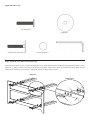
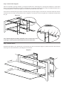
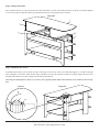
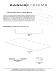
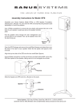
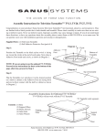
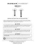
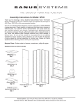
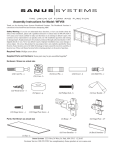
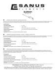
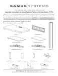
Assembly Instructions for Natural Furniture: Model NF203, NF213, NFV49
Thank you for choosing the Natural Furniture line from Sanus Systems. If you have any questions regarding this or any other Sanus
Systems product, please contact us at 800.359.5520 or visit us at www.sanus.com. Our customer service representatives can assist you
quickly with any issues regarding assembly or missing parts. Check carefully to make sure none of the parts are missing or defective.
Never use defective parts. Replacement parts for products purchased from an authorized dealer will be shipped directly to you. Please
call Sanus Systems before returning products to retail stores.
Supplied Parts List:
(12) Steel Cross Tube - b
(8) Three Hole Plate - c
(1) Front Frame - a
(2) Glass Shelf - d
(2) Rear Support - e
(1) Top Glass Shelf - g
(2) Plastic Wire Cover - f
(4) Wire Strap - h
Sanus Systems 2221 Hwy 36 West. St. Paul, MN 55113
800.359.5520 www.sanus.com 8.31.04
Supplied Hardware List:
(12) Allen Bolt - i
(4) Washer - j
(12) Decorative Face Bolt - k
(8) Glass Protector - l
(1) Allen Key - m
Step 1: Attach the Cross Tubes to the Front Frame
Position the Front Frame (a) like it is pictured in Diagram 1. Next, slide each Decorative Face Bolt (k) through the Front Frame, a Three
Hole Plate (c) and into a Steel Cross Tube (b). Repeat process until all 12 Steel Cross Tubes are fastened to the Front Frame. See the
Detailed View of Diagram 1 for assistance. Tighten the Steel Cross Tubes firmly by hand.
Diagram 1
Detailed View
b
c
k
a
Step 2: Attach the Rear Supports
Thread an Allen Bolt (i) through a Washer (j), through the middle hole in a Rear Support (e), through the middle hole in a Three Hole
Plate (c) and into the middle Steel Cross Tube (b). See Diagram 2 for assistance. Repeat the process until all 4 middle Allen Bolts, the 4
accompanying Washers, and the Rear Supports are attached to the middle Steel Cross Tubes.
Next, thread an Allen Bolt through each hole of the Wire Strap (h), the Rear Support, each outer hole of the Three Hole Plate and into
each outer Steel Cross Tube. See the Detailed View of Diagram 2 for assistance. Proceed to tighten all 12 Allen Bolts with the Allen
Key (m).
Diagram 2
Detailed View
b
c
e
j
i
h
Note: The Rear Supports should be positioned so the set of three holes closest
to the edge is at the top and so the horizontal slots face the front frame.
Step 3: Add Glass Shelves
Install the Glass Shelves (d) so that the back of each shelf fits into the slot in the Rear Support (e) and the front of the shelf sits down
into the groove in the Front Frame (a). See Diagram 3 for assistance.
Diagram 3
a
d
e
slot
Step 4: Add Top Glass Shelf
Place 4 Glass Protectors (l) evenly along the top of the Front Frame (a). Next, Add 2 Glass protectors to the top of each Rear Support
(e). Proceed to place the Top Glass Shelf (g) onto the Glass Protectors. See Diagram 4 for assistance.
Diagram 4
g
l
a
l
e
Step 5: Add Plastic Wire Covers
To add the Plastic Wire Covers (f) insert one edge of the Wire Cover into one of the slots in the Rear Support (e) as shown in the Top
View of Diagram 5. Proceed to insert the other edge of the Wire Cover into the adjacent slot in the rear support. Repeat the process for
the other Plastic Wire Cover. This completes the assembly of the NFV49.
Note: The glass in Diagram 5 is shown as a cutaway view to provide greater detail of how the Wire Cover attaches to the rear support.
Top View
Diagram 5
f
slot
h
slot
e
Sanus Systems 2221 Hwy 36 West. St. Paul, MN 55113
800.359.5520 www.sanus.com 8.31.04