1
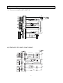
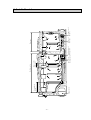
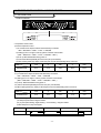
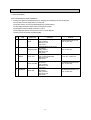
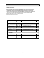
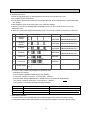
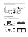
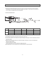
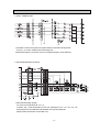
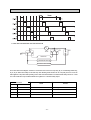
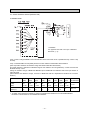
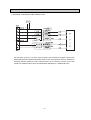
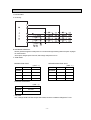
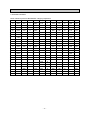
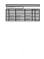
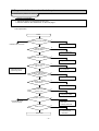
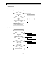
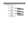
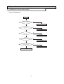
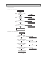
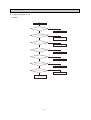
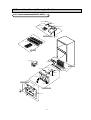
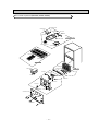
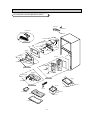
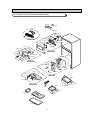
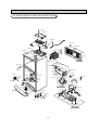
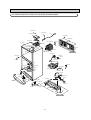
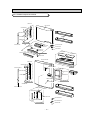
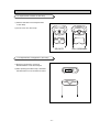
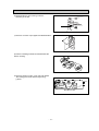
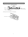
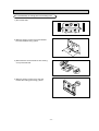
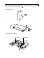
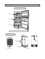
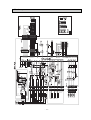
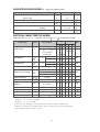
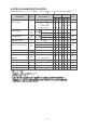
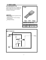
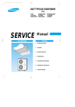
Model: SR-61KTC/SR-61NMC
SR-65KTC/SR-65NMC
SR-69NMC
REFRIGERATOR
CONTENTS
1. Product Specifications
1
2. Safety Warning & Caution
2
3. Electrical part specifications & standard
4
4. Electric diagram
6
5. Air Circulation route
7
6. Function & Vsing method
8
7. Temperature control & other Functions
11
8. Circuit Operating theory
21
9. Failure diagnosis & repairment
36
10. Dissembie & Assemble drowing and part LIST 53
11. Disassemble & Assemble Method
88
12. Packing
84
13. Main componets specification
86
1. Product specifications.
510 MODEL
STANDARD
550 MODEL
590 MODEL
SR69-NMC
589LT
SR-65NMC
554LT
165LT
SR-65KTC
514LT
165LT
SR-61MNC
TOTAL
153LT
424LT
SR-61KTC
FREEZER
389LT
REFRIGERATOR
98 KG
361LT
MODEL NAME
ITEM.
●Classification by Capacity
NET
CAPACITY
840*761.5*1760.5
97 KG
840*761.5*1854.5
840*761.5*1755.5
96 KG
AC240V / 50HZ
378W
AC220V / 50~60HZ
50Hz
388W
AC127V / 60Hz
50~60Hz
AC 240V
378W
AC240V / 50HZ
60Hz
AC 220V
388W
AC220V / 50~60HZ
50Hz
AC 127V
STANDARD
840*761.5*1810.5
NET DIMENSION
NET WEIGHT
ELECTRIC HEATING EQUIPMENT
POWER
●Classification by Electric power
ITEM.
AC127V / 60Hz
50~60Hz
AC 240V
SR-61NMC, 65NMC, 69NMC
60Hz
AC 220V
SR-61KTC, 65KTC
REGULAR FREQUENCY
AC 127V
MODEL NAME
REGULAR VOLTAGE
COOLING MASS SEALED QUANTITY
COOLING MASS
SORT OF REFRIGERATOR
4 STAR
150 G
HFC-134α
OCCASSIONAL COOLING TYPE REFRIGERATOR
ELECTRIC MOTOR REGULAR POWER
FREEZER PERFORMANCE
- 2 -
2.Safety precautions and warnings
xRead all instructions before using this product and keep to the instructions
in order to prevent danger or property damage.
Warning/Caution
Description of symbols
IN DICATES PROHIBITION
Warning
Indicates that a
danger of death
or serious injury
exists.
DO NOT DISASSEMBLE
DO NOT CONTANT
ADHERE THE INSTRUCTION STRICTLY
Caution
Indicates that a risk
of personal injury
or material damage
exists.
ONPLUP FROM THE ELECTRICAL
AVOLD
EARTH THE APPLIANCE TO AVOID THE
RISK OF AN ELECTRIC SHOCC
Warning
Do not insert the power cables.
●May cause abnormal
generation of heat or fire.
Do not disassemble to
repair or alter.
Do not bend the power cable with
excessive force or do not have the
power cord pressed by heavy article.
● It may cause fire or abnormal
operation which leads to injury.
● May cause fire.
Prohibition
Do not
disassemble
Check the operating environment.
Make sure of the earth.
●Deterioration of electric parts insulation
may cause electric shock or fire.
● If power doesn’t ground, it will
cause breakdown and electric shock.
Pull the power plug out to exchange
the interior lampof the refrigerator.
● It may cause electric shock.
Unplug
Earth
25cm
- 3 -
Caution
Do not put bottles or kinds of
glass in the freezer.
● Freezing of the contents may inflict a
wound.
Prohibition
Do not store articles on the
Refrigeration.
● Opening or closing the door may
cause things to fall down, wihch
may inflict a wound.
Do not store narrow and lengthy Do not store pharmaceutical
bottles or foods in a small multi- products, scientific materials,
etc., in the refrigerator.
purpose room.
● It may hurt you when refrigerator door ●The products which temperature control
should not be stored in the refrigerator.
open and close.
Prohibition
Prohibition
When replacing electric
comporents, be sure to use rates
comporents.
On repair, make sure that the wires
such as harness are tightly
bundled.
●Check the model, rated voltage, rated
current, operating temperature etc. of
the component.
●Tghtly bundle wires in order not
to be detached by the external
force and to be wetted.
Reted nents
compo
Prohibition
On repair, remove completely dust or
other things of housing parts,
harness parts, and check parts.
● Cleaning may prevent the possible fire by
tracking or short.
After repair, check the assembled
state of components.
Check the electrical parts for the
trace of moisture.
●It must be in the same assembled state
when compared with the state before
disassembly.
●When the trace of moisture penetration is
detected, replace the patt or try insulation
tapping.
- 4 -
3. ELECTRIC PARTS STANDARD
STANDARD
ITEM
SR-61/65/69NMC / SR-61/65KTC
TEMPERATURE
REFRIGERATION PARTS
MODEL
COMPRESSOR
110~115V/60Hz
127V/60Hz
220V/50~60Hz
230~240V/50Hz
DK172C-L2U
DK172P-L2U
SK190H-L2U
DK190Q-L2U
STARTING TYPE
RSCR
OIL CHARGE
Freol α-15(ESTER)
FREEZER
SPLIT FIN TYPE
COOLER
REFRIIGERATOR
CONDENSER
FORCED AND NATUAL CONUECTION TYPE
DRYER
MOLECULAR SIEVE XH-9
CAPILLARY TUBE
0.82X2500 4.26Kg/cm2
REFRIGERANT
HFC-134a
ON(℃)
OFF(℃)
ON(℃)
OFF(℃)
HIGH
-21℃
-23℃
-22℃
-24℃
MID
-18℃
-20℃
-18℃
-20℃
LOW
-15℃
-17℃
-15℃
-17℃
HIGH
-0.5℃
-1.5℃
-0.5℃
-1.5℃
MID
3.5℃
2.5℃
2.5℃
1.5℃
LOW
6.5℃
5.5℃
5.5℃
4.5℃
FREEZER
REFRIGERATOR
FIRST CYCLE
DEFROST
SPLIT FIN TYPE
SPLIT FIN TYPE & TUBE TYPE
4hours±10minute
REFRIGERATOR
10hours
FREEZER
20hours
CYCLE
PAUSE TIME
10minute±2minute
- 5 -
ITEM
SR-61/65/69NMC / SR-61/65KTC
110~115V/60Hz
SENSOR
F-SENSOR
502 AT
R-SENSOR
〃
F-DEF SENSOR
〃
R-DEF SENSOR
〃
230~240V/50Hz
DRAIN HEATER
13W / 110V
13W / 127V
13W / 220V
13W / 240V
F DEF HEATER
235W / 220V
235W / 127V
235W / 220V
235W / 240V
R DEF HEATER
120W / 110V
120W / 127V
120W / 220V
120W / 240V
DID HEATER
10W / 110V
10W / 127V
10W / 220V
10W / 240V
HEATER
ELECTRIC PARTS
220V/50~60Hz
127V/60Hz
F DEF FUSE
250V 10A 72±4℃
R DEF FUSE
250V 10A 72±4℃
CONDENSER
12㎌ / 250VAC
MODEL
J531QE100M2002
J531Q34E100M350-2
J531Q35E330M385-2
START
10Ω±20%(SURROUNDING TEM 25℃)
220Ω±20%
(SURROUNDING TEM 25℃)
330Ω±20%
(SURROUNDING TEM 25℃)
4TM314RHBYY-53
4TM265RHBYY-53
STARTING RELAY
4TM437RHBYY-53
MADEL
O/L-PROTELTOR
DC TRANS
5㎌ / 350VAC
OPERATION
ON TEM
69℃
69℃
69℃
61℃
OFF TEM
130℃
125℃
130℃
130℃
SR-61/65/69NMC
115V 50/60Hz
127V 50/60Hz
220V 50/60Hz
240V 50/60Hz
SR-61/65/69NMC
110V 60Hz
127V 60Hz
220V 50/60Hz
240V 50Hz
F-COOLER FAN MOTOR
SR-61 / 65KTC
SR-61/65/69NMC
12V, DC - BLDC , SENSORLESS
110V 60Hz
127V 60Hz
220V 50~60Hz
230~240v 50Hz
R-COOLER FAN MOTOR
SR-61 / 65KTC
SR-61/65/69NMC
CYCLE FAN MOTOR
12V, DC - BLDC , SENSORLESS
110V 60Hz
SR-61 / 65KTC
127V 60Hz
220V 50~60Hz
230~240v 50Hz
12V, DC - BLDC , SENSORLESS
F-LAMP
110 / 130V 15W
240V 15W
R-LAMP
130V 30W
240V 25W
DID DOOR-S/W
SR-61 / 65KTC
250V/0.7A
250V 0.7A
DOOR-S/W
Power cord
EP-2,127V/7A
- 6 -
SPT-3,125V/7A VCP-2,250V/10A BF-3,250V/10A
4. Electric diagram
4-1. Electronic mode(SR-61KTC,65KTCT)
BLU
BLU
VLT
BLK
WHT
ORG
GRY
RED
RED
P.T.C RELAY
SIBLU
SIBLU
BLK
SIBLU
OPERATING
CONDENSER
BLK
EARTHED
CIRCUIT BLK
VLT
GRY
VLT
YEL
YEL
RED
GRN
COMP RELAY
COMPERESSOR
EMI
FILTER
BLK
RED
ORG
RED
F-TEM FUSE BLK
BRN
RED
F-DEFROST-HEATER
RED
GRY
GRY
SIBLU
BLK
BRN
RED
VLT
VLT
BLK
BRN
RED
SIBLU
ORG
PNK
BLU
VLT
GRY
WHT
SIBLU
WHT
BRN
YEL
BLK
BRN
RED
SIBLU
ORG
PNK
BLU
VLT
GRY
WHT
SIBLU
WHT
RED R-TEM FUSE
BLK
BLK
R-DEFROST-HEATER
GRY
GRY
GRY
REFRIGERATOR
GRY
ORG
W/B
W/B
RED
PNK
RED
FREEZER LAMP
4-2) SEMI BASIC (SR-61NMC, 65NMC, 69NMC)
GRY
EARTHED WHT
CIRCUIT
FREEZER FAN MOTOR
ORG
ORG
YEL YEL
BLU
REFRIGERATOR LAMP
VLT
FREEZER LAMP
BLK
BRN
PIK
RED
COMP RELAY
OPERATING CONDENSER
SIBLU
COMPRTSSOR COOLER MOTOR
RED
RED
F DEFROST-NEATER
BRN
RED
F ERM FUSE
RED
WHT
SIBLU
WHT
RED
PIK,BLU
RED
BRN
RED
WHT,BLK
SIBLU
SIBLU
GRY
DOOR SWITCH
RED
GRY
GRY
SIBLU
YEL
FREEZER FAN MOTOR
WHT R DEFROST-NEATER RED
-7-
R ERM FUSE
RED
RED
RED
WHT
EARTHED GRN
CIRCUIT
BLK
Compressor
Vegetabele
part
Cooler of Cooling fan of
RefrigeratorRefrigerator
Case of Re
frigerator
Refrigerator
Cooler of Cooling fan of
Freezer
Freezer
Freezer
5. Cool Air Circulation
-8-
6. FUNCTIONS AND DIRECTIONS
F
10
6-1. THE OUTER SIZE
17
D
G
E
10
71.5
9
A
C
9.5
B
840
11
MODEL
A
B
C
D
E
F
G
SR-61KTC
1066.5
580
1755.5
761.5
617.5
1479
123
SR-61NMC
1066.5
580
1760.5
761.5
617.5
1479
123
SR-65KTC/NMC
1096.5
600
1810.5
761.5
617.5
1479
123
SR-69NMC
1140.5
600
1854.5
761.5
617.5
1479
123
-9-
6-2. THE NAME OF EACH PARTS AND DISASSEMBLE METHOD
DOOR GUARD
FREEZER SHELF
●
●
Up the front of shelf to direction ① then pull and
apart to direction②.
Push to direction ②
2
1
2
CHILLED ROOM SHELF
DID CASE
●
Pull and apart
display part of
door guard.
2
1
●
●
Pull to the arrow direction
then up and apart at the
locking point.
VEGETABLE/SALAD COVER AND CASE
TEMPERRD GLASS TRAY
●
●
Up and apart
as showed.
●
Pull with both hands as showed
The height can be adjusted according to the stored bowls.
-10-
Upthe cover and apart then pull out the vegetable//salad
compartment cover and case at the mid-point and up
and pull to apart.
6-3. CYCLE OF FREEZING
COMPRESSOR → SUB CONDENSER → CLUSTER PIPE → HOT PIPE → DRYER → CAPILLARY TUBE
→ EVAPORATOR OF REFRIGERATOR → EVAPORATOR OF FREEZER → ACCUMULATOR →
SUCTION PIPE → COMPRESSOR
SUCTION PIPE
CLUSTER PIPE
ACCUMULATOR
EVAPORATOR OF
REFRIGERATOR
EVAPORATOR OF
FREEZER
CAPILLARY
TUBE
COMPRESSOR
DRYER
SUB CONDENSER
HOT PIPE
-11-
7. TEMPERATURE CONTROL AND THE OTHERS
7-1. ELECTRONIC MODE
1. DISPLAY DESIGN
2. Temperature control function
1) Freezer temperatur control
1-1) It consists of five steps as follows and selected by one button.
MID → MID,HIGH → NIGH → LOW → LOW,MID
1-2) setting up turn on a light in order by system of freezer cholce button.
( MID → MID,HIGH → NIGH → LOW → LOW,MID → MID...)
1-3) It set up“MID”automaticature during power on.
1-4) There is standard temperatically list of each notch part. (1/3H standard)
1-5) When inputting freezer key, display of LED change at once but actual operating start in 10 seconds
ITEM
NOTCH
TEMPERATURE
LOW
⊙
MID
⊙
HIGH
-16.0℃
-17.5℃
-19.0℃
-20.5℃
-22.0℃
2) Refrigerator temperature control
2-1) It consists of five steps as follows and selected by one button.
MID → MID,HIGH → NIGH → LOW → LOW,MID
2-2) setting up turn on a light in order by system of freezer cholce button.
( MID → MID,HIGH → NIGH → LOW → LOW,MID → MID...)
2-3) It set up“MID”automaticature during power on.
2-4) There is standard temperatically list of each notch part. (1/3H standard)
2-5) When inputting freezer key, display of LED change at once but actual operating start in 10 seconds
ITEM
NOTCH
TEMPERATURE
LOW
⊙
MID
⊙
HIGH
+6.0℃
+4.5℃
+3.0℃
+1.0℃
-1.0℃
3) Ppwer freezering / Regular condition /9in bed)
1) It select just power freezer / Regular condition.
2) If you press power freezing / regular freezing → Power freezing → Regular condition.
3) When first power on, lamp does appear.
CLASSIFICATION
First POWER ON
Pressed once
Pressed twice
LAMP CHANGE
OFF
POWER freezing
Regular condition operating
-12-
3-1) Power freeze function
A. Input power freeze/regular condetion key. When power freeze startes, LED signal change at once.
(Comp and F-fan runs continuously for two and a half hours when quick freeze sekected.)
B. During quick freezing the refrigerator controlled by setted notch.
3-2) Regular condition function
A. Judge the temp. of F/R room, F room is over comp on of“LOW”NOTCH or R room is over comp on of“LOW”NOTCH.
If so regular condition function isn’t performed and LED is OFF below 0.5 seconds.
B. Input the function, judge temp. of F room or R room, F room is less than comp on of“LOW”NOTCH and R room is less than
comp on of“LOW”NOTCH. If so regular condition function is operate and comp F,R-FAN is off without state of operation in recently.
C. When state the operation of regular condition, judge the temp. of F/R room, F room is over comp on of“LOW”NOTCH or R room is
over comp on of“LOW”NOTCH. If son regular condition function is the end and it is returned before.
4) Power refrigerator/Power saving function
1) Select power refrigerator/power saving button
2) Press POWER/SAVING BUTTON at once. And it is selected“OFF”“Power refrigerator”“Saving operation”.
3) Initial power on isn’t signal.
CLASSIFICATION
INITIAL POWER ON
PRESS ONE
CHANGE OF SIGNAL LAMP
OFF
POWER REFRIGERATOR
PRESS T ONE
NOTES
SAVING OPERATION NOTES
4-1) Power refrigerator function
A. Input power refrigerator/saving key. When power refrigerator started, LED signal change at once.
(Comp. and R-fan runs until the temperature of refrigerator reaches -4℃ when quick refrigeration selected.)
B. During power refrigerator the freezing controlled by setted notch.
4-2) Saving operation function.
A. Input saving operation button, F/R room temp. operate 0.8℃ rising. (When situation about NOTCH, rised 0.8℃)
B. When input power freezer or power refrigerator, saving function stop to the end of power function and saving operation is
performed after the end of power function.
※ When power freeze and refrigeration selected at the same time
- Each function applied at the same time Power freeze runs Comp. and F-fan for two and half hours and power refrigeration runs
Comp. and R-fan for -4℃ and power refrigeration runs.
3. Alarming
1) Button touch(
“Ding-Dong”sound)
1-1) Everytime the button pushed, the input confirmation,“Ding-Dong”sound.
1-2) Not sounds, if two keys are pushed at the same time or wrongly handled
2) Door-Open Warning
2-1) Two minutes after door opened, alarming sounds.
2-2) If door opened continuously, ten times of alarming sounds with one minute cycle.
2-3) Alarming stopped just after door closed.
-13-
3) Forced operating and defrosting“Beep”
(
sound)
3-1) If forced function selected the“Beep”sounds.
3-2) Alarming sounds until the forced operating canceled by automatically(24Hr) or manualy.
3-3) Alarming sounds until the forced defrosting canceled by automatiically(24Hr) or manualy.
4) Defrosting
1-1) From the first power on, defrosting started after 4 hours of total Comp on time.
1-2) After that defrosting cycle can be varied from 6 hours to 24 hours.(Comp on time)
5) Testing
◆ Testing is for PCB, product, function and service.
◆ After testing, turn the power on to start self diagmosis.
1) Fored operating
1-1) As the button on PCB pushed once, Comp starts immediately.
1-2) If fored operating selected the notch of freezer and refrigerator fixed to“HIGH”and“MID-HIGH”
. Then comp and
F-fan is controlled to pull down and R-fan is controlled to“MID-HIGH”notch.
1-3) Pull-down maintained just for 24 hours during forced operating, after that automatically defrost freezer and refrigerator
and then stares nomal operating.
1-4) Turn the power off or select test cancel mode to cancel the forced operating.
1-5) Alarming (0.25 secon/0.75 sec off) continues until the forced operating finished. It continues without any relations
to alarming key selection or cancel.
2) Forced defrosting
2-1) Push the test button one more time to run the forced defrosting of refrigerator.
2-2) One more push in the above status will run defrosting of freeaer and refrigerator simult a neously.
2-3) Forced operating cancelled automatically by starting forced defrosting and return to normal operating
after campletion of defrosting.
3) Test cancel mode
3-1) One more push in the status of forced defrosting of F/R wiill run normal operating.
3-2) Alarming stopped in the test cancel mode.
4). Initial function of first POWER ON.
1) If power is impressed, it begins to make a self diagnosis and light all LED for 2 second if normal condition is confirmed.
2) After first self diagnosis find unstable sensor among temp. sensor. And LED is on and off 5 second periods.
3) During 2 second turn on all LED. AND F/R LED display“MID-MID”
4) Early state R-EVA and F-EVA sensor is all below 15℃.
And R defrosting HEATER and F defrosting HEATER is perform per 0.5 second turn on.
5) After early state R-EVA sensor temp. or F-EVA sensor is over 15℃ and F/R defrosting is end per 3 second,
COMP and F-FAN, R-FAN is turn on per 0.5 second and operated per 5 minutes without temp. condition.
6) Input TEST S/W among 4) and 5) movemen 5 it is the end and perform TEST function.
-14-
5. SELF DIAGNOSIS
1) SELF DIAGNOSIS AT FIRST POWER ON
1-1) As the power applied to the refrigerator first time, all dispays show operating and run the self diagnosis.
1-2) If no problem foundes, display returns to normal mode
1-3) If probiem foundes, on and off the related display lamp and start alarming.
1-4) Lamp displayed until the problem solved or seif diagnosis cancelled.
1-5) After problem solved the display mode return to nomal.
1-6) After refrigerator repaired, sure to power off and on to run self diagnosis.
1-7) Refer to belows for problem and related displays.
NO
ITEM
1
R-SENSOR
2
RD-SENSOR
3
ROOM-TEMP
DISPLAY LED
Refrigerator
“LOW”
SYMPTOM
Refrigerator sensor houslng disconnection
Faulty connection
Wire open or short
Faulty sensor
Refrigerator defrost sensor houslng
disconnection
Refrigerator“MID” Faulty connection
Wire open or short
Faulty sensor
Room-Temp senser LEAD disconnection
Faulty connection(PCB MAIN)
Wire open or short
Faulty sensor
SENSOR
Freezer“LoW”
4
F-SENSOR
5
FD-SENSOR
Freezer defrost sensor houslng
disconnection
Freezer“LOW,MID” Faulty connection
Wire open or short
Faulty sensor
Freezer defrost sensor houslng
disconnection
Freezer“MID”
Faulty connection
Wire open or short
Faulty sensor
( SELF-DIAGNOSIS DISPLAY TABLE) )
-15-
REMARK
R-SENSOR temperature is over
+50℃ or below -50℃
RD-SENSOR temperature is over
+50℃ or below -50℃
Room-Temp sensor temperature
is over +50℃ or below -50℃
ZF-SENSOR temperature is over
+50℃ or below -50℃
FD-SENSOR temperature is over
+50℃ or below -50℃
6. LOAD STATUS DISPLAY
1) Press power freezing / regular conditing and power refrigerating / power saving key for five seconds then
press temperature control key in the refrigerator after temperature display lamps on and off three times
2) This mode shows which lamps is being sourced signal from MICOM currently. This doesn’t mean the load is
operate due to the open wire or relay missing though the display shows the compressor operating.
3) Load status display return to normal mode after sixty seconds.
4) Follows are load status and related dispay.
NO
ITEM
DISPLAY LED
DISPLAY
FREEZER SUBORDINATE
1
COMP
FREEZER ”LOW”
RELEVANT LED ON DURING COMPRESSOR OPERATION
2
F-FAN
FREEZER ”LOW,MID”
RELEVANT LED ON DURING F-FAN OPERATION
3
FREEZER DEFROST HEATER
FREEZER ”MID”
RELEVANT LED ON DURING FREEZER DEFROST HEATER ON.
REFRIGERATOR SUBORDINATE
4
R-FAN, S-FAN
REFRIGERATOR ”LOW”
RELEVANT LED ON DURING S-FAN AND F-FAN OPERATION
5
REFRIGERATOR DEFROST HEATER
REFRIGERATOR ”MID”
RELEVANT LED ON DURING REFRIGERATOR DEFROST
MODE DISPLAY
6
INITIAL MODE
POWER FREEZER
RELEVANT LED ON QITH INITIAL POWER INPUT.
7
OVERLOAD
POWER REFRGERATOR
RELEVANT LED ON QHEN ROOM-TEMP. IS OVER 35℃
8
LOW TEMP MODE
POWER SAVING
RELEVANT LED ON QHEN ROOM-TEMP. IS BELOW 15℃
(LOAD STATUS DISPIAY TABLE)
-16-
7. operating of fan motor
1) FAN MOTORoperates BLDC MOTOR by dc power.
2) After first starting power, it operates“HIGH”rpm to off dot of fan and then operates“LOW”rpm
3) if binding motor or not sensing regular freguency of motor to pcb, motor will stop operating.
(After stopping, reoerating start in 10 seconds.)
※ F, R, C-FAN operate equal.
8. OPTION TABLE
1) Temperature change TABLE of Freezer ( ● : Pertinent DIODE )
SHIFT
4
3
2
1
SHIFT
4
+0.5
●
+1.0
●
+1.5
●
●
+2.0
●
●
+2.5
●
●
+3.0
●
●
+3.5
●
●
●
+4.0
●
●
●
●
SHIFT
8
7
6
5
+0.5
●
+1.0
●
+1.5
●
●
+2.0
●
●
+2.5
●
●
+3.0
●
●
+3.5
●
●
●
+4.0
●
●
●
STANDARD TEMPERATURE
-0.5
●
-1.0
●
-1.5
●
-2.0
●
-2.5
●
-3.0
●
●
-3.5
●
●
●
●
●
3
2
1
●
●
●
2 ) Temperature change TABLE of refrigerator ( ● : Pertinent DIODE )
SHIFT
8
7
6
5
STANDARD TEMPERATURE
●
-0.5
-1.0
●
-1.5
●
-2.0
●
-2.5
●
-3.0
●
●
-3.5
●
●
●
●
●
-17-
●
●
●
●
※ Personal Informatin
Micomport Voltage and Resisting force of sensor by Temperature.
TEMPERATURE(℃) RESISTANCE
VOLTAGE (V)
TEMPERATURE (℃) RESISTANCE
VOLTAGE(V)
TEMPERATURE (℃)
RESISTANCE
VOLTAGE(V)
TEMPERATURE(℃)
RESISTANCE
VOLTAGE(V)
-42
98870
4.541
-19
30920
3.778
4
11250
2.647
27
4650
1.587
-41
93700
4.518
-18
29500
3.734
5
10800
2.596
28
4487
1.549
-40
88850
4.494
-17
28140
3.689
6
10370
2.545
29
4329
1.511
-39
84150
4.469
-16
26870
3.644
7
9959
2.495
30
4179
1.474
-38
79800
4.443
-15
25650
3.597
8
9569
2.445
31
4033
1.437
-37
75670
4.416
-14
24510
3.551
9
9195
2.395
32
3894
1.104
-36
71800
4.389
-13
23420
3.504
10
8839
2.346
33
3760
1.366
-35
68150
4.360
-12
22390
3.456
11
8494
2.296
34
3631
1.322
-34
64710
4.331
-11
21410
3.408
12
8166
2.248
35
3508
1.298
-33
61480
4.301
-10
20480
3.360
13
7852
2.199
36
3390
1.266
-32
58430
4.269
-9
19580
3.310
14
7552
2.151
37
3276
1.234
-31
55550
4.237
-8
18730
3.260
15
7266
2.104
38
3167
1.203
-30
52840
4.204
-7
17920
3.209
16
6992
2.057
39
3062
1.172
-29
50230
4.170
-6
17160
3.159
17
6731
2.012
40
2962
1.143
-28
47770
4.134
-5
16430
3.108
18
6481
1.966
41
2864
1.113
-27
45450
4.098
-4
15740
3.057
19
6242
1.922
42
2770
1.085
-26
43260
4.061
-3
15080
3.006
20
6013
1.878
43
2680
1.057
-25
41190
4.023
-2
14450
2.955
21
5792
1.834
44
2593
1.030
-24
39240
3.985
-1
13860
2.904
22
5581
1.791
45
2510
1.003
-23
37390
3.945
0
13290
2.853
23
5379
1.749
46
2429
0.977
-22
35650
3.905
1
12740
2.801
24
5185
1.707
47
2352
0.952
-21
33990
3.863
2
12220
2.750
25
5000
1.667
48
2278
0.928
-20
32430
3.822
3
11720
2.698
26
4821
1.626
49
2206
0.904
-18-
7-2, SEMI ELECTRONIC MODE
A. Temperature control part design
Freezer temperature control
refrigerator temperature control
TEMP, FRE
TEMP, REF
B. Temperature control function
1) Tempera ture choice of freezer
·You can choose to ⑧ From ①
·Follows are control temperature by KNOB position.
KNOB position
①
②
③
④
⑤
⑥
⑦
⑧
control temperature
-16.0
-17.0
-18.0
-19.0
-20.0
-21.0
-22.0
-23.0
2) Temperature choice of refrigerator
·You can choose to ⑧ From ①
·Follows are control temperature by KNOB position.
KNOB position
①
②
③
④
⑤
⑥
⑦
⑧
control temperature
5.0
4.0
3.0
2.0
1.0
0
-1.0
-1.0
NOTE) Temperature contol of freezer and refrigerator is position control by ROTRAY S/W, if it get out of
position it control NOTCH
C. Defrost function
1) Defrost set up by time of COMP ON.
2) Defrost tun Heating → Rest time
3) When initial power on, initial defrost run defrost of freezer and refriger ator in 4 hours of COMP
ON. Since initial
(R →R, F →R →R, F ... Cycle operating))
4) ON/OFF of defrost - heater control by EVA-SENSOR If EVA-SENSOR is problem (short 10 pen),
it run just rest time and then finishes defrost function without heating.
5) During defrosting it maintain COMP and FAN state and after finish defrost-heating rest time
is 10 minutes.
6) Follows are defrost heating ON point and OFF point that operate by EVA-SENSOR.
HEATER ON dot
HEATER OFF dot
REFRIGERATOR
FREEZER
BEIOW+10℃
BEIOW -5℃
17℃
-19-
REMARK
D. TEST FUNCTION
▶ TEST function is function for test,SVC and fair test of PCB and product.
▶ TEST S/W choose and confirm function of product and then POWER ON to run self diagnosis.
1) FORCED OPERATING FUNCTION
● Pressed once TEST S/W on MAIN PCB. If so COMP and F-FAN run at once. Thus be careful because
occur COMP over load.
(Refrigerator FAN control ON/OFF by temperature)
● Since it set up forced operating function, it always run COMP and F-FAN and display lamp on MAIN
PCB with ON/OFF 0.1 second periodically.
(Refrigerator FAN control ON/OFF by temperature)
● In 24 hours forced operating function of freezer and refrigerator operate and finish then run normal mode
by KNOB position of temperature setting up.
● During forced operating function if you want to stop it first power OFF and then power on or choose
TEST cancellation mode.
2) Forced defrost function
● For forced operating pressed once TEST S/W button, it cancel forced operating at once and refrigerator
forced defrst function with display forced defrost position ON/OFF lamp on MAIN PCB 0.5 secoonds
periodically. If press one more TEST S/W bueeon display refrigerator and freezer defrosting.
● If forced defrost choose, COMP and FAN power OFF and defrost heater on at once, At this time,
if sensing temperature of EVA-SENSOR over 12℃ defost heater power off and operate rest time normal mode.
● After heating finish it need 10 minal mode
3) TEST FUNCTION CANNCELLATION MODE
● Duting refrigerator and freezer run forced defrost function press one more TEST S/W button if so forced
defrost cancel and rest in 10 minutes and then turn normal mode.
-20-
E. self diagnosis function
1) Power on refrigerator and it run seif diagnosis function about 2 seconds at the inner part.
2) If no preblem it turns normal mode.
3) If find prebiem display lamp of PCB show errw position like lower list and everything don’t operate until repair
error position.
4) After refrigerator power off and then power on for confirming conditiom.
5) Thus if you want to know OPEN/SHORT of temperature sensor on SVC, power off and on if it run self
diagnosis function.
6) When error occur LAMP display method.(Lamp on time : 0.3 seconds ( ON/OFF) Lamp off time : 2 seconds)
No.
ITEM
1
F DEFROST
SENSOR
On
Off
2
R DEFROST
SENSOR
On
Off
3
F SENSOR
On
Off
4
R SENSOR
On
Off
5
F Rotary S/W
On
Off
-.OPEN ERROR
6
R Rotary S/W
On
Off
-.OPEN ERROR
7
NORMAL MODE
On
Off
Problem
Led Display
-.OPEN ERROR
Remark
-. SENSOR IS BELOW -50℃
-.SHORT ERROR -. SENSOR IS BELOW +50℃
-.OPEN ERROR -. SENSOR IS BELOW - 50℃
-.SHORT ERROR -. SENSOR IS BELOW +50℃
-.OPEN ERROR -. SENSOR IS BELOW - 50℃
-.SHORT ERROR -. SENSOR IS BELOW +50℃
-.OPEN ERROR -. SENSOR IS BELOW - 50℃
-.SHORT ERROR -. SENSOR IS BELOW +50℃
Vntil operating initial 5minutes
● In case of many problems find it display error position in order.
<Example of error display>
① When problem R-ROOM SENSOR display lamp operating.
(0.3 seconds ; ON/OFF) Four times →2 seconds OFF - REPEAT ② When problem R-ROOM SENSOR and F-ROOM sensor at the same time display method.
(0.3 seconds ; ON/OFF) Three times →2 seconds OFF - REPEAT ※ Tem perature contre control operating by ROTRAY SWITCH
OPEN ERROR
SHORT ERROR
SECTION
INITIAL SEIF DIAGNOSIS(OFF/ON)
STOP ERROR DISPLAY OPERATING
“HIGH”
“MID”
OPERATING
OPERATING BEFORE OPEN STEP
“HIGH”
OPERATING BEFORE SETTING UP STEP
F. Quick heating operating
1) If freezer heating sensor OPEN/SHORT error at freezer heating it runs just rest time without heating..
2) If refrigerator heating sensor OPEN/SHORT error at refrigerator heating it runs jest time without heating.
-21-
8. CIRCUIT OPERATING THEORY
8-1. ELECTRONIC MODE
1. Power suooly part
1) Power is on and makes about DC 300V through BD1.
2) TOP S/W is switching the best condition automatically.
Electric current run between D and S of TOP S/W and occur electric current in TRANS and when power of D-s is
off storing electric current of TRANS pass to secondary voltage.
3) Voltage main 12V. This is applied to display, relay and 5V power of sourcr and Main PCB
2. OSCILLATOR
TERMINAL
FREQUENCY
Xin(#30)
4MHz
Xout(#31)
4MHz
1) Tish needs function for CLOCK occurrence and time calculation.
In case of SPEC of RESONATOR change abnormal mode run because of changing Timming system of MICOM.
3. RESET PART
-21-
TERMINAL
VOLTAGE
Vcc
DC 5V
RESET
DC 5V
1) RESET part is intialize RAM of MICOM and others when power is on or power is inferruoted for some time It will make
whole program runs from the first status. When power is supplied, reset voltage is“LOW”status for a few seconds and
turn into“HIGH”(Vcc Voltage) status in the normal opweating.
4. DOOR S/W SENSING PART
ITEM
DOOR CONDITIONS
DOOR S/W CONTACT
LAMP
F
CLOSE
OPEN
OFF
ON
OUTMODE
OPEN
CLOSE
ON
OFF
5V
CLOSE
OPEN
OFF
ON
OUTMODE
OPEN
CLOSE
ON
OFF
5V
R
CN72PIN NO1 CONTACT MICOM INPUT VOLTAGE
1) DOOR S/W sensing part doesn,t sense Door of Fand R room on each micom.
2) Lamp control door is opened, door S/W pin NO 3 opened and voltage no touching No1 of CN 27 and MICOM input Then the
door-open is sensed.
3) When the door is opened, Door S/W pin No 3 opened and voltage no touching No 1 of CN No 27 and MICOM input.
Then the door-open is sensed.
→ It makes door alarm after 2 minutes
This time F,R DOOR must close at the same time for stopping Door alarm.
4) DID DOOR S/Whave no each sensing parts and control lamp ON/OFF by contact dot of DOOR.
-22-
5. TEMP·SENSING PART
1) Thermistor is used for sensing which has negative resistance coffiecient to the temperature.
R 302, 4, 6, 8, 12, C301~C306 are pares for preventing noise.
2) MICOM input voltage, Vf of sensor is Vf=(R+hx x Vcc)/(R301+Rth) (Rth : sensor resistance)
6. KEY SCAN AND DISPLAY PARTS
1) KEY SCAN and display operating
It is used for No 5 of MICoM NO #2, 3, 4, 5, 6,
It operates“high”10 msec periodically for 2 msec cycle : MICOM pin No : #2 → #3 → #4 → #5 → #6
This signal pass by IC 04 (UDN 2981 or KID 65783AP) from Input dot to Dotput dot.
Voltage of peak to peak is about 11V (DC RMS 1.5V)
-23-
7. COMP AND DEFROSTING HEATER OPERATING
GRY
RED
COMP LED
F-DEFROSTING HEATER
R-DEFROSTING HEATER
As it is seen above block diagram. 220V line is connected to the commons of comp relay, Ry 71 and defrosting heater relay,
Ry 73, Ry 75. When those relays are off state comp and defrosting heater are also off. As comp relay moves to on and AC
220V applied to comp load it starts operating On the other hand defrost heater runs if defrost heater relay moves to on. There
is no chance that both comp and defrost heater runs together so it’s useful for safety aspect.
STATES
LOAD
REMARK
COMP
F DEFROSTING HEATER
ON
OFF
COMP OPERATION
ON
ON
COMP OFF, F-DEFROSTING HEATER OFF
OFF
ON
F-DEFROSTING HEATER ON
OFF
OFF
COMP OFF, F-DEFROSTING HEATER OFF
-24-
preverting power of F-DEFROSTING HEATER
PREVENTING COMP POWER
8. BLDC MOTOR Operation Circuit
1) Operate description of BLDC MOTOR First, if FAN became before operate condition of FANMOTOR, condition of in the temp.
are high temp. more than FAN of recently institutionn NOTCH is operated condition.
ex)CONNECTOR CN 70’S third voltage : Input VL, Vcc 5V(Used Diode regard DROP)
Perated High RPM
V L = Gain * Ei
Gain = (R705+R704)/R704
Ei = R703/(R701+R703) * Vcc
= (20K + 10K)/10K
= 10K/(820 + 10K)*4.4
=3
= 4.07
V L = 4.07*3=12.24 (Change it for resistance error)
1-1) FANMOTOR in the freezer(F-FAN)
A. If refrigerator’s power is confimated, check the temp. of F-FAN and temp. more than F-FAN on is operated“HIGH RPM”to sign
of MICOM #13 PORT. After arrived FAN OFF, if FAN is OFF and separate function of ON.OFF isn’t confimated always NICOM
#12 PORT is confimate sign and operated“LOW RPM”
B.“HIGH RPM”is determinated the resistance of R701, LOW RPM is determinated the resistance of R702.
C. When check RPM, check the wire to resistance of R715 and it is knew to MOTOR RPM.(wire *4)
D. Operated condition to Motor is received wire sign to MICOM #7 PORT but if it isn’t regular wire, FAN is stopped and operate again
after 5 minutes.
※ When power freeze and forced operation, always operated“HIGH RPM”without temp. of freezer.
-25-
1-2) FAN MOTOR IN THE FREEZER (R-FAN)
A. If refrigerator’s power is confimated, check the temp. of R-FAN and temp. more than R-FAN ON is operated “HIGH RPM” to sign
of MICOM #11PORT. After arrived FANOFF, if FAN is OFF and separatre function of ON/OFF isn’t confimated always
MICOM#10PORT is confimate sign and operated “LOW RPM”.
B. “HIGH RPM” is determinated the resistance of R706, LOW RPM is determinated the resistance of R707.
C. When check RPM, check the the wire to resistance of R716 and it is knew to MOTOR RPM.(wirw*4)
D. Operated condition to MOTOR is received wire sign to MICOM #8PORT but if it isn’t regular wire, FAN is stopped and operate again
after 5minutes.
※ When power refrigerate and forced operation, always operated “HIGH RPM” without temp. of freezer.
1-3) COMP FAN MOTOR
A. If refrigerator’s power is confimated, check the operated condition of F,R-FAN and F,R-FAN is HIGH RPM is operated #HIGH RPM to
sign of MICOM #20PORT. After arrived F,R-FAN OFF, if FAN is OFF and seperate function of ON/OFF isn’t confimated always
operated “LOW RPM”
B. “HIGH RPM” is determinated the resistance of R711, LOW RPM is determinated the resistance of R711,R729.
C. When check RPM, check the wire to resistance of R717 and it is knew to MOTOR RPM (wire *4).
D. Operated condition to MOTOR is received wire sign to MICOM #9PORT but if it isn’t regular wire, FAN is stopped and operate again
after 10minutes.
E. COMP FAN is always HIGH RPM, if it is HIGH RPM.
※ When power freeze and refrigerate, forced operation, always operated “HIGH RPM”
-26-
9. POTION PART
1) PRINCIPIE OF MAVEMENT
Like the GRID waves appear in initial POWER ON is reaeved through SWITCHING DIODE and OPION
is judged for MATRIX method.
NAME
STANDARD
R-CARBON
10Kohm-J (1/4)
R-CARBON
1Kohm-J (1/4)
※ when OPTION Changed power turns off, after change and power turn on.
-27-
REMARK
8-2. SEMI ELECTROMAGNETIC
9-1. POWER PART.
V12(DC 12V)
FUSE
250V, 0.5A
Vcc(DC 5V)
KA7805
KA7812
VAR1
GRY
C101
1000uF/35V
LVT
CON 70
YW396-07AV
C102
470uF/25V
C105
104
C103
470uF/25V
C104
104
IN4007*4
D101~104
RED
CON 71
YW396-05AV
POWER
CIRCUIT OF USING
- ● Vcc(DC 5V)
POWER AROUND MICOM OR SENSOR SENSING PART
- ▶ V12(DC12V)
RELAY RUNNING PART
AC220V input power is decompressed through LVT(DC-TRANS), the power is changed DC vltg through DIODE rectification. It is
an archery practive bow through 1000uF/35V CAPACITOR. And regular DC 12V is output through REGULATOR 7812, it is used
to the RELAY runing power. The other of LVT(DC-TRANS) is an archery pratice bow through DIODE rectification or 1000Uf/35V
CAPACITOR and it is output the regular DC5V through REGULATOR 7805.
And it is used sircumference circuit or various signal(Sensor,Switch) input power.
9-2. Departure circuit PART
TERMINAL
ERUPTION QAVEIENGTH
Xin
Xout
4.00MHz
4.00MHZ
less than ±0.5% error
Element of inside MICOM is copper ware clock production of informations transmission, reception and eruption circuit for time calculation.
In a case change SPEC of X-TAL use the standard parts or SPEC because it changes calculated time at MICOM or doesn’t run.
-28-
9-3. RESET CIRCUIT PART
RESET circuit part is performed the eariy state all
program furction when input power and confimate
power to MICOM for suddeniy electricity failure, it is
initialed to PAM of inside MICOM. when confimate
power RESET’S vltg is“LOW”state during
sevweal tens uses and it is“HIGH”state as nomal
operation state.
9-4. SENSING OF TEMP PART
SENSOR OPEN
Inpat MICOM“HIGH”
SENSOR SHORT
Inpat MICOM“LOW”
1) SENSOR is vsing the THER with labor coefficint, if temp. is high, resistance is low on the contrary if temp.
is iow, reissitarce is high.
2) According to sensor, voltage of input to MICOM is calculate,
Vf =
Rth
X Vcc(Vcc:5V, Rth:SENSOR RESISTANCW)
Rth + 10㏀
-29-
9-5. TEMP. CONTROL CIRCUIT.(ROTARY S/W)
A. FREEZER TEMP.
※CAUTION
It is appeared the S/W cross spot of ROTARY
S/W circuit ①∼⑩
Temp. control is changed KNOB of contructed ROTARY S/W in the freezer and it is possible the temp. control 1 step
to 8 step.
Temp. control SETTING become partial pressure for R 501 resistance and ROTARY S/W resistance.
(Row composition resistance of resistance charge to R 908 and ROTARY S/W direction)
And partial pressure is delivered to MICOM through R 503 resistance and recognited temp. control and it become
SETTING to temp. contol.
Voltage or resistance charge of MAIN PCB MICOM input for SUB PCB Ass’s ROTARY S/W cross spot direction is
same the below.
(When Measure the resistance charge, connector of MAIN PCB CN 30 is separated and measure the connector
terminal.)
Section
1 STEP
2 STEP
3 STEP
4 STEP
5 STEP
6 STEP
7 STEP
8 STEP
WHEN OPEN
(9PIN)
(8PIN)
(7PIN)
(6 PIN)
(5 PIN)
(4 PIN)
(3PIN)
(2 PIN)
THE OPEN SPOT
Voltage
2.77
2.94
3.12
3.33
3.57
3.84
4.16
4.54
(R504)
±0.15V
±0.15V
±0.15V
±0.15V
±0.15V
±0.15V
±0.15V
±0.15V
Resistance
6.54㏀±
5.66㏀±
4.76㏀±
3.84㏀±
2.91㏀±
1.96㏀±
0.99㏀±
(CN30⑥~⑦)
1%
1%
1%
1%
1%
1%
1%
0Ω
0.1~ 0.7V
100㏀±1%
※ To upside, when measure the resistance charge isn’t appeared the resistance in the case SUB PCB ASSY
connection is disconnection or crack situation of PCB board.
-30-
B. REFRIGERATOR TEMP
※ CAUTION
It is appeared the S/W cross spot of ROTARY
S/Wcircuit ①~⑩.
Temp. control is changed KNOB of contructed ROTARY S/W in the refrigerator and it is possible the temp. control 1 step to 8 step.
Temp. control SETTING become partial pressure for R502 resistance and ROTARY S/W resistance.(Row composition resistance of
resistance charge to R908 and ROTARY S/W direction). And partical pressure is delivered to MICOM through R505 resistance and recognited
temp. control and it become SETTING to temp. control. Voltage or resistance charge of MAINPCB MICOM input for SUBPCB Assy’s
ROTARY S/W cross spot direction is same the below.(When measure the resistance charge, connector of MAINPCB CN30is separated and
measure the connector terminal.
Section
1 STEP
(PIN #9)
2 STEP
(PIN #8)
3 STEP
(PIN #7)
4 STEP
(PIN #6)
5 STEP
(PIN #5)
6 STEP
(PIN #4)
7 STEP
(PIN #3)
8 STEP WHEN OPEN
(PIN #2) THE CROSS SPOT
Voltage
2.77
2.94
3.12
3.33
3.57
3.84
4.16
4.54
(R506)
±0.15V
±0.15V
±0.15V
±0.15V
±0.15V
±0.15V
±0.15V
±0.15V
Resistance
6.54㏀±
5.66㏀±
4.76㏀±
3.84㏀±
2.91㏀±
1.96㏀±
0.99㏀±
(CN30⑥~⑦)
1%
1%
1%
1%
1%
1%
1%
0Ω
0.1~ 0.7V
100㏀±1%
※ To upside, when measure the resistance charge isn’t appeared the resistance in the case SUBPCB ASSY connection is
disconnection or crack situation of PCB board.
-31-
6. ELECRICAL LOAD SIGNAL LAMP CONTROL PART
BARISTER
GRY
SSR71
SSR72
RY71
RED
RY72
RY73
Like the above circuit, pin 1 of CN71 suply the power. And electrical load suply the power when
electricaload operated. operated refrigerator, freezer to fact comp operation And if it is needness of
defrosting operation, performed comp’s electrical load is off, it is security of circuit. In fact, each
operation is operated to temp. sensor and absoluteness defrosting isn’t operated with comp.
-32-
7. POTION PART
A. circuit way
B. MOVEMENT PRINCIPAL
like the grid waves appear in initial power on is recieved throngh switching diode and option is judged
for matrix method.
when option changed power furnd off, after change and power turns on.
C. TEMP SHIFT
FREEZER TEMP SHIFT
(UNIT : ℃)
SHIFT
602
REFRIGERATOR TEMP SHIFT
(UNIT : ℃)
601
STONDAR
SHIFT
604
603
STONDAR
●
D -1.0
-2.0
●
+1.0
●
●
D -1.0
●
-2.0
●
+1.0
●
●
FROSTING TEMP SHIFT
(UNIT : ℃)
SHIFT
605
STONDAR
10 hours
D
7 hours
※ CAUTION
Don’t change DIODE OPTION escape D601~D605, becase it is related to Refrigerator’s frust.
-33-
※ PERSANAL INFORMA
sensor resistance power and MICOMPORT voltage by temperature.
TEMPERATURE (℃) RESISTANCE (Ω)
VOLTAGE (V)
TEMPERATURE RESISTANCE (Ω)
VOLTAGE (V) TEMPERATURE (℃) RESISTANCE (Ω)
VOLTAGE (V) TEMPERATURE (℃) RESISTANCE (Ω) VOLTAGE (V)
-42
98870
4.541
(℃)
30920
3.778
4
11250
2.647
27
4650
1.587
-41
93700
4.518
-19
29500
3.734
5
10800
2.596
28
4487
1.549
-40
88850
4.494
-18
28140
3.689
6
10370
2.545
29
4329
1.511
-39
84150
4.469
-17
26870
3.644
7
9959
2.495
30
4179
1.474
-38
79800
4.443
-16
25650
3.597
8
9569
2.445
31
4033
1.437
-37
75670
4.416
-15
24510
3.551
9
9195
2.395
32
3894
1.104
-36
71800
4.389
-14
23420
3.504
10
8839
2.346
33
3760
1.366
-35
68150
4.360
-13
22390
3.456
11
8494
2.296
34
3631
1.322
-34
64710
4.331
-12
21410
3.408
12
8166
2.248
35
3508
1.298
-33
61480
4.301
-11
20480
3.360
13
7852
2.199
36
3390
1.266
-32
58430
4.269
-10
19580
3.310
14
7552
2.151
37
3276
1.234
-31
55550
4.237
-9
18730
3.260
15
7266
2.104
38
3167
1.203
-30
52840
4.204
-8
17920
3.209
16
6992
2.057
39
3062
1.172
-29
50230
4.170
-7
17160
3.159
17
6731
2.012
40
2962
1.143
-28
47770
4.134
-6
16430
3.108
18
6481
1.966
41
2864
1.113
-27
45450
4.098
-5
15740
3.057
19
6242
1.922
42
2770
1.085
-26
43260
4.061
-4
15080
3.006
20
6013
1.878
43
2680
1.057
-25
41190
4.023
-3
14450
2.955
21
5792
1.834
44
2593
1.030
-24
39240
3.985
-2
13860
2.904
22
5581
1.791
45
2510
1.003
-23
37390
3.945
-1
13290
2.853
23
5379
1.749
46
2429
0.977
-22
35650
3.905
0
12740
2.801
24
5185
1.707
47
2352
0.952
-21
33990
3.863
1
12220
2.750
25
5000
1.667
48
2278
0.928
-20
32430
3.822
2
11720
2.698
26
4821
1.626
49
2206
0.904
-34-
ABOUT CIRCUIT LINK LIST
NO
CODE-NO
SPEC
MODEL NAME
Quantity
1
DA32-10109H
R-SENSOR ASSY
502AT
2
DA32-10109A
F-SENSOR ASSY
502AT
1
3
DA32-10105G
EVA SENSOR ASSY
502AT
2
4
DA41-00048A
MAIN PCB ASSY
AC220V/50,60Hz
1
5
DA41-00012A
SUB PCB ASSY
-
2
6
DA26-30116A
DC-TRANS
AC220V/50,60Hz
1
7
DA41-00053A
MAIN PCB ASSY
AC220V/50,60Hz
1
-35-
Remark
1
GENERALLY
SEMI
Applicating
SEMI DID HEATE
9. Diagnosis of disorder and method of repair
1. ELECTRICAL (SR-61KTC,65KTC)
Preliminary examamination
1. Check the power of consent and power code
2. Check it based on the :References” on the next pages.
1. No input Power
START
Ohiy aline AC 220V FUSE?
POWER CARD connection
Y
Change main fuse
N
N
Is confimate 220V the
CN10 both sides?
Check the eletric wire
construction
Y
Y
Only a line FUSE of MAINPCB?
Change fuse-250V 2A
N
N
Is confimate 300V the
BD 1(+),(-),?
-CautionMAIN PCB power part is
appesred high-pressure.
Change PCB PATTERN
and change BD1
Y
Is confimate DC5.
8Vthe the TOP S/W 223Y
among ‘C-S’?
N
Change PCBASSY
Y
N
Is confimate 12v the both
C104sides to?
Y
Change D102(D10SC9M)
N
Is confimate 5v the both
sides to c103?
Y
Change Reg1 (7805)
N
Is PANEL PCB O.K?
LEAD WIRE CABI, DOOR
(Cooent to the upside)
1. Check assembly line
and repair
2. Change parel PCB
Y
N
Is RELAY O.K?
1. Change pertinet RELAY.
2. Check contacted
LEADWIRE.
Y
Nomal state
-36-
2. Self diagnosis failure
Outer temper ature sensor failure
START
N
Is main PCB connection O.K?
Connection failure, SHORT
Y
N
Is outertemp sensor O.K?
Change temp sensor,
change PCB MAIN
Y
N
Is input vltg of MICOM
PIN#58 O.K?
Check Main-PCB
Y
PCB and temp sensor O.K.
Reconfirm outertemp sensor inferior
② Refrigerator temp, sensor failure
START
N
Is temp sensor O.K?
change sensor
Y
N
Is MAIN-PCB Connection
(con30) O.K?
Connection failune Re-connection
Y
N
Is input vltg of MAIN-PCB
(con30) pin2 O.K
Cheak connected sensor wire
Y
N
Is input vltg of
MICOM pin#60 O.K
Cheak short and iced lead
Y
PCB and temp sensor O.K.
Reconfirm connector inferior.
-37-
Refrigerator’
s defrosting sensor failure
START
N
Is MAIN-PCB connection
(con30) O.K?
Connection failure
Y
N
Is defrosting sensor O.K.
Change sensor
Y
N
Is connection of defrosting
sensor O.K
Connection failure
Y
N
Is input vltg of
CON30PIN60 O.K.
Wire open
Y
Change MAIN PCB ASS’Y
Freezer tem sensor failare
START
N
Is MAIN-PCB connection
(con30) O.K?
Connection failure
Y
N
Is temp sensor O.K
Change sensor
Y
N
Is connection of temp
sensor O.K
Connection failure
Y
N
Is input vltg of
CON30PIN80 O.K.
Wire open
Y
Change MAIN PCB ASS’Y
-38-
Freezer’s defrosting sensor failure
START
In MAIN-PCB connection
(con30) O.K?
N
Connection failure
Y
N
Is defrosting sensor O.K.
Change sensor
Y
Is conection of defrosting
sensor O.K
N
connection failure
Y
N
Is input vltg of CON30
PIN4 O,K
Wire open
Y
Change MAIN PCB ASS’
Y
-39-
3. In case of contiunous alarming
REFRENCES
F/R door open alarms for ten seconds after 2 minutes later.
IF door opens continuously, door open alarms for ten seconds with one minute cycle. cten
times of“Ding-Ding”
If there is moisture in door S/W, it is shorted and alarms due to the MICOM’S misjudgement,
In this case the inside lamps of freezer and refrigerator turns off so the lamp do not turns on
thaugh you open the door.
If the door S/M is rusted, the sighal of door open do not reach to MICOM and no alarms and
lamps turhed off continuously.
① In case of continous Melody
START
Is the Door S/W O.K?
N
Change the Door S/W
Y
Is MAIN PCB connection
(con72) O.K?
N
Connection failure
Y
Does the ultg of con72 pln3.
1 and AC220V change?
N
Wire open, change door S/W
Y
Change main PCB ass’
y
-40-
② In case of“Beep-Beep”alarming
START
N
Is forced operating/fro
sting selected?
Cancel forced oper/defro
Y
N
Is it the same when power
on again?
MAIN-PCB O.K
Y
PCB MAIN TEST S/W (SW1);lead
touch, check shorted other material
REFRENCES
There is on“beep-beep”alarming except the forced operating/frosting or sensing troble during
self diagnosis
If self diagnosis sensed troble, it is displayed on the PANEL PCB, so easy to check, If not, the
forced operating/frosting is selected the NOTCH status are“High”-”Mid,High”at that time.
③ In case of no PANEL PCB display
START
Is the connection of COVER O.K?
N
Connection failure
Y
Is MAIN-PCB connection (CON50) O.K?
N
Re-connectin
Y
Is PANEL-PCB connection O.K?
N
Re-connection connection failure
CHANGE PANEL PCB
-41-
④ In case of the panel PCB Key selection is impossible.
START
Is the connection of
cover O.K?
N
Re-connection connection failure
Y
Is MAIN-PCB commection
(CON50)O.K?
N
Re- connection
Y
N
Is PANEL-PCB connection O.K?
Re-connection connectionfailure
Y
Y
Are there any keys already
predded?
Re-assemble PANEL COVER
N
Change PANEL-PCB
4. In case of FAN do not run
REFRENCES
“Be sure to check cooling FAN under forced operation”
1. F-FAN, R-FAN and COMP COOLING are off when COMP is off.
2. Though the comp is on, the R-FAN is not always on because the FAN is off when the tem
perature was reached to the set point.
3. There is delaying time to run the fan after door open (COMP ON state). thedelay time varys
from ten seconds to one minute, (Forced operation included)
4. When closed MOTOR, it is stop state (After stopped, it is ON/OFF at ten minutes)
-42-
① In case of F-FAN doesn’t run (Run the DC voltage)
START
N
Is it forced operation?
Forced operation
Y
Does it run lmin after the door
S/W pressed?
Y
F-FAN O.K
N
Is confivcate AC 220V of the
MAIN PCB connection
CN72 PIN 1.3?
N
Re-connection CON72
Check wire
Y
Does the door
S/W works norks nomally
N
Change DOOR S/W
Y
Is 5V vltg MAIN PCB MICOM
PIN27?
Y
Change MAIN PCB
N
Has vltg the MAIN PCB
connection CN70 pin 2?
(12V or 9V)
N
Check CON70 Connection
Check the MOTOR
Y
N
Has wave the MAIN PCB
connection CN70 pin 5
Check MOTOR
Change MOTOR
Y
Check IC 06 KA324 Change MAin PCB
-43-
② In case of R-fan doesn’t run (Run the DC voltage)
(Reference BLDC MOTOR run circuit)
START
N
Is it forced operation?
Forced operation
Y
Y
Does it run lmin after the door
S/W pressed?
F-FAN O.K
N
Is confivcate AC 220V of the MAIN
PCB connection CN72 PIN 1.3?
N
Y
Re-connection CON72
Check wire
Does the door
S/W works norks nomally
N
Change DOOR S/W
Y
Is 5V vltg MAIN PCB MICOM
PIN27?
Y
Change MAIN PCB
N
N
Has vltg the MAIN PCB
connection CN70 pin 2?
(12V or 9V)
Check CON70 Connection
Check the MOTOR
Y
Has wave the MAIN PCB
connection CN70 pin5?
N
Check MOTOR Change
MOTOR
Y
Check IC 06 KA324 Change MAin PCB
-44-
③ In case of COMP FAN doesn’t run (run the DC voltage)
(Reference the BLDC MOTOR run circuit.)
START
N
Is it forced operation?
Forced operation
Y
Has vltg the
MAIN PCB connectionPIN3 of
CN70?(12V or 9V)
N
Y
Check CON70 connection check
the MOTOR
Has qave-length the
MAIN PCB connection
pin7 tof CN70?
N
Check the MOTOR Chang the MOTOR
Y
Check IC 06 KA 324
Change MAIN PCB
-45-
9. Diagnosis of disorder and method of repair.
2. SENMI electronic mode (SR-61NMC, 65NMC)
1. When not operating Power
START
Is power voltage output between MAIN
PCB PIN5 of CN 70 and PINI of CN 71?
Repair POWER CORD and electric cord.
Is TRANS secord side voltage of MAIN
PCB normal?
Exchange DC-TRANS.
Is FUSE normal?
Exchange FUSE.
Is iced lead near MAIN PCB soldering and
SHORT phenomenon?
Repair iced iead
Is defrst relay and comp relay during operating
TEST S/W of NAIN PCB normal?
Repair PCB
Exchange MAIN ASSY
-46-
2. Self diagnosis failure
A. Freezer’s temp·sensor failure
START
Is freezer’s temp·sensor O.K?
change temp ,senser
Is MAIN PCB connection
(CON30) O.K?
Connection failure Re-connection
Is connection of temp sensor O.K?
Check connected sensorwire
Is input vltg of MICOM pinll O.K?
Check short and iced lead
PCB and temp, sensor O.K
Ckeck connection Charge MAIN PCB
B. Refrigerator’s temp, senser failure
START
Is refrigerator’s temp·sensor O.K?
change temp ,senser
Is MAIN PCB connection
(CON30) O.K?
Connection failure Re-connection
Is connection of temp sensor O.K?
Check connected sensorwire
Is input vltg of MICOM pin 10 O.K?
Check short and iced lead
PCB and temp, sensor O.K
Ckeck connection Charge MAIN PCB
-47-
C. Freezer’s defrosting sensor failure
START
Is freezer’s defrosting sensor O.K?
Change sersor
Is Main PCB connection
(con30)O.K?
Connection failure Re-connection
Is connection of detrosting sensor O.K?
Check connected sensor wire
Is input of MICOM pin 9 O.K?
Check lead and short
PCB and temp.sensor O.K
Check connection. change MAIN PCB.
D. Refrigerator’s defrosting sensor failure
START
Is Refrigerator’s defrosting sensor O.K?
Change sersor
Is Main PCB connection
(con30)O.K?
Connection failure Re-connection
Is connection of detrosting sensor O.K?
Check connected sensor wire
Is input of MICOM pin 8 O.K?
Check lead and short
PCB and temp.sensor O.K
Check connection. change MAIN PCB.
-48-
3.In case of FAN in the refrigerator doern’t run
REFRENCES
“Be sure to check cooling FAN under forced operation”
1. Freezer FAN, refrigerator FAN and COMP COOLING are off when COMP is off.
2. Though the COMP is on, the FAN is not always on because the FAN is off when the temperature
was reached to the set point (Forced operation included)
3.There isn’t delaying time to run the fan after door open (COMP on state)
A. In case of F-Fan do not run
START
Select Forced operation
Forced operation
Does it run after the door S/W pressed?
F-FAN O.K
Does the door S/W works nomally
Change Door S/W
In MAIN PCB connection O.K?
Re-connection CN70
Output MICOM pin 19 sigral?
Change lead and MICOM change PCB
Is 5V the IC3(KA2657)
#16 singval?
IC3(KA2657) Failure
Check ssr(SSR71), Change
MAIN PCB ASSY
-49-
B. In case of R-FAN do not run.
① Check
START
Select Forced operation
Forced operation
FAN is operating condition to ROTRAY
S/W or SENSOR?
Reference checked ROTARY S/W
and changed set up.
Does it uun after the door S/W pressed?
F-FAN O.K
Does the door S/W works nomally?
Change DOOR S/W
Is MAIN PCB con70 connection O.K?
Re-connection CON70
Output the MICOM pin#18 stghal?
Change lead and MICOM chang PCB
Is 5V IC3(KA2657) #15 signal?
IC3(KA2657) Failure
Chesk ssr (ssr72) change
MAIN PCB ASSY
-50-
② Check ROTARY S/W
START
Is proper the retrigerator's
temp·regulator?
Regulate temp regulator
Is temp·regulator O.K?
Change temp,regulator
Is ROTARY S/W vltg and resistance of
MAIN PCB O.K?
Fix connect part and wire
Is retrigerator's sensor resistaance O.K?
(Referce separate temp.TABLE)
Change refrigerator's sensor
Fix MAIN PCB ASSY and
COMP connector
-51-
4. Badress management of freeze cycle
Appearance
Cause
Caun termeasure
EVAP is cold and warm
COND is warm, when EVAP
is cold.
This movement is reply.
Interruption for
moisture(Iced)
Pour into ice.
Cond is cold EVAP isn’t cold.
Comprssor temp. is high.
Other material is
infiltrated and cooling
cycles is interrupted
SUCTION PIPE is same the
DISCHARGE PIPE.
EVAP doesn’t cold COND is same
the nomal temperature.
Product frost to suction PIPE
Ouerheat of COND.
Cooling state of EVAP be
ineffective.
COND is cold
Surace temp of compressor is high
Refrigerator isn’t cold at once
Check interrupt section and
repairs.
Badness the
compressor
Change compressor
full of ice
Pour into ice
About a haif of EVAP is
covered frost and particular
freeze becase disclosure the
ice is ilttle.
-52-
After weid the
disclosure part,
pour into ice.
10. Disassemble and Assemble Drawing And Parts List
10-1. Freezer comoartment(SR-61KTC, 65KTC)
LAMP-INCANDE SENT
VAMP-HOLDER
SENSOR-ASSY
COVER-LAMP FRE, B
COVER-LAMP FRE, A
COVER-LAMP FRE,ASSY
SCREW
SHELF-FRE
TRIM-SHELF
TRAY-ICE
SHELF-FRE,ASSY
SENSOR-ASSY
CAVER CASE-ICE
THERMO-FUSE, ASSY
EVAP-FRE, ASSY
CASE-ICE CUBE
WIRE-HARNESS
GR0MMET-MOTOR
EVAP-FRE
SCREW-TAPPING
COVER-MOTOR
MOTOR-FAN
BUMPON-MOTOR
FAN-SIROCCO
COVER-EVEP FR, ASSY
SPRING-FAN
COVER-EVAP REAR
COVER-FAN, A
COVER-EVAP RE, ASSY
SCREW
CAP-SCREW
COVER-EVAP, FRONT
-53-
HEATER-DRAIN
10-2. Freezer compartment (SR61NMC,65NMC,69NMC)
WIRE HARNESS-ROTART
SCREW-TAPPING
LAMP-INCANDESENT
LAMP-HOLDER
SENSOR-ASSY
PBA-PANEL
CASE-LAMP FRE, ASSY
SCREW-TAPPING
CASE-LAMP, FRE
KNOB-TEMP, CONTROL, F
COVER-LAMP, FRE
SHELF-FRE
TRIM-SHELF
TRAY-ICE
SHELF-FRE,ASSY
SENSOR-ASSY
CAVER CASE-ICE
THERMO-FUSE,
ASSY
EVAP-FRE, ASSY
EVAP-FRE
MOTOR-FAN
COVER-MOTOR
CASE-ICE CUBE
SCREW-TAPPING
HEATER-DRAIN
GR0MMET-MOTOR
BUMPON-MOTOR
FAN-SIROCCO
SPRING-FAN
COVER-EVAP REAR
COVER-EVAP, FR, ASSY
CAP-SCREW
SCREW-TAPPIG
- 55 -
10-3. Refrigerator Compartment (SR-61KTC, 65KTC)
COVER-LAMP,FRE
LAMP-INCANDESENT
THERMO-FUSE, ASSY
SENSOR-ASSY
SCREW-TAPPING
COVER-MOTOR
WIRE HARNESS-MOTOR
EVAP-REF
COVER-MOTOR
GROMMET-MOTOR
EVAP-REF, ASSY
COVER-EVAP REAR
MOTOR-FAN
FAN-SIROCO
INS-ASSY
SPACER-COVER EVAP
BUMPON-MOTOR
SPRING-FAN
COVER-EVAP,REAR,ASSY
SENSOR-ASSY
CATALYST-LTC
SEAL-CUTT, M/F
COVER-PURIFIER
CAP-SCREW
SCREW-TAPPING
COVER-EVAP, FRONT
SCREW-TAPPING
COVER-EVAP, FR ASSY
COVER-LAMP
SPACER-DUCT,A
SHELF-REF, UPP
SEAL-DUCG,REAR
COVER-DUCT,REF
CAP-SCREW
RAIL-CHIL ROOM,L
GROMMET-RAIL
COVER-DUCT,ASSY
CASE-VEG(L)
RAIL-CHIL RBM, R
SCREW-MACHINE
SHELF-REF UPP,ASSY
FIXER-ROLLER
ROLLER-FRE
CASE-VEG(R)
CASE-VEG, ASSY(L)
RAIL-VEG, MID
FIXER-ROLLER
TRAY CHILLED ROOM
ROLLER-FRE
SHELF-REF, ASSY
CASE-VEG, ASSY(R)
COVER-VEG, ASSY
-55-
10-4. Refrigerator Compartment (SR-61NMC,65NMC,69NMC)
COVER-LAMP,FRE
LAMP-INCANDESENT
THERMO-FUSE, ASSY
SENSOR-ASSY
SCREW-TAPPING
SCREW-TAPPING
COVER-MOTOR
EVAP-REF
GROMMET-MOTOR
COVER-EVAP REAR
EVAP-REF, ASSY
FAN-SIROCO
INS-ASSY
BUMPON-MOTOR
SPACER-COVER EVAP
GROMMET-MOTOR
SPRING-FAN
SCREW-TAPPING
PBA-PANEL
ISCREW-TAPPING
KNOB0TEMP CONTROL,R
SENSOR-ASSY
COVER-EVAP,REAR,ASSY
CATALYST-LTC
COVER-PURIFIER
WIRE HARNESS ROTART
COVER-EVAP, FRONT
SEAL-CUTT, M/F
SCREW-TAPPING
CAP-SCREW
COVER-EVAP, FR ASSY
SCREW-TAPPING
SEAL-DUCG,REAR
COVER-LAMP
SPACER-DUG,A
SHELF-REF, UPP
CAP-SCREW
COVER-DUG,REF
RAIL-CHIL ROOM,L
COVER-DUG,ASSY
GROMMET-RAIL
CASE-VEG(L)
SCREW-MACHINE
RAIL-CHIL RBM, R
FIXER-ROLLER
ROLLER-FRE
SHELF-REF UPP,ASSY
CASE-VEG, ASSY(L)
CASE-VEG(R)
RAIL-VEG, MID
FIXER-ROLLER
ROLLER-FRE
TRAY CHILLED ROOM
CASE-VEG, ASSY(R)
SHELF-REF, ASSY
COVER-VEG, ASSY
- 57 -
10-5. Related Components of CABI & UNIT (SR-61KTC,SR-65KTC)
SCREW-TAPPING
COVWE-PCB PANEL
PBA-MAIN
C-OIL
SCREW-TAPPING
CBF
SCREW-TAPPING
SCREW-TAPPING
CORE-FERRITE
TRANSE-DC
ABSORBER-COMP
C0OIL(REW)
CASE-PCB PANEL
TUBE-PVC
PIPE-SUB, COND ASSY
ASSY-CABI FOAM
COVER-HINGE UPP
COVER-COMP
SCREW-TAP TLTE
SHIN-HINGE
PIPE. CONNEG
HINGE-UPP
COVER-COMP, ASSY
GROMMET-SUB COND
BOMPON-MOTOR
SCREW-TAPPING
SCOEW-TAPPING
BUMPON-MOTOR
MOTOR-FAN
GROMMET-MOTOR
CAP-SCREW
FIXER-MOTOR CIRCUIT
SWITCH-DOOR
SHAFT
SHIM-HINGE-MID
SCREW-TAP TITE
CASTER-FRONT
FAN-SIROCCO
WIRE HARNESS
MOTOR
REINF-CASTER
SPRING-FAN
DRYER-ASSY
TRAY-DIWATER
SCOEW-TAPPING
PIPE-CONNEG,ASSY
HINGE-MID
RIVET
WASHER
SCREW-FRONT
SCREW-TAPPING
HING-MID-ASSY
COMPRESSOR
CLAMP-COMP
SCREW-SPECIAL
TRAY-D/WATER ASSY
HINGE-LOW
DROMMET-COMP
WASHER
SCREW EARTH
COVER-LEG FRONT
PTL-RELAY
SHIM-HINGE LOW
REINF-CASTER
CASTER FRONT
O/L-PROTELTOR
RIVET
FOOT-ASSY
SCREW-TAP TITE
COVER-RELAY
CHASSIS-COMP
SCREW-TAP TITE
RIVET
CASTER0REAR
CHASSIC-COMP ASSY
- 58 -
10-6. Related Components of CABI & UNIT (SR-61NMC,SR-65NMC,69NMC)
SCREW-TAPPING
SCREW-TAPPING
CBF
COVWE-PCB PANEL
SCREW-TAPPING
ABSORBER-COMP
CASE-PCB PANEL
PBA-MAIN
TUBE-PVC
C-OIL
PIPE-SUB, COND ASSY
ASSY-CABI FOAM
SCREW-TAPPING
COVER-HINGE UPP
FIXER-HINGE UPP
SCREW-TAP TLTE
COVER-COMP
SHIN-HINGE
PIPE. CONNEG
HINGE-UPP
COVER-COMP, ASSY
GROMMET-SUB COND
MOTOR-CIRCUIT
FAN-SIROCCO
SCREW-TAPPING
SPRING-FAN
SCREW-TAPPING
CAP-SCREW
SWITCH-DOOR
SCREW-TAPPING
SHAFT
DRYER-ASSY
SHIM-HINGE-MID
SCREW-TAP TITE
PIPE-CONNEG,ASSY
HINGE-MID
TRAY-D/WATER,ASSY
WASHER
SCREW-TAPPING
HING-MID-ASSY
COMPRESSOR
CLAMP-COMP
SCREW-SPECIAL
DROMMET-COMP
HINGE-LOW
WASHER
SHIM-HINGE LOW
PTL-RELAY
SCREW EARTH
REINF-CASTER
COVER-LEG FR
O/L-PROTELTOR
CASTER FRONT
COVER-RELAY
SCREW-TAP TITE
FOOT-ASSY
RIVET
CHASSIS-COMP
SCREW-TAP TITE
RIVET
CASTER0REAR
CHASSIC-COMP ASSY
- 59 -
10-7. Related Components of DOOR
HANDLE-FRE
ASSY-DOOR FRE
SCREW-MACHINE
REINF-HANDLE FRE
SCREW-TAPPING
GUARD-FRE
SCREW-MACHINE
HANDLE-FRE, ASSY
HANDLE-TRIM FRE
STOPPER-DOOR, FRE
PBA-PANEL
BUTTON UPP,L
COVER-DISPLAY
BUTTON LOW,L
CASE-DISLAY
STOPPER-DOOR
SCREW-HANDLE
BUTTON UPP,R
BUTTON LOW,R
GUARD-EGG
CASE-DISPLAY-ASSY
CASE-DLSPLAY, ASSY
GUARD-EGG, R
SCREW-TAPPING
TRAY-EGG
ASSY-DOOR FOAM REF
HANDLE-REF
SCREW-MACHINE
SWITCH-DOOR BUTTON
GUARD-EGG
HANDLE-TRIM REF UPP
CASE-DID UTILTY,A
REINF-HANDLE REF
CASE-DID UTILITY,B
SCREW-TAPPING
GROMMETGUARD
GUARD-DID
GROMMET-HINGE DID
COVER-DID, UTILITY
CASE-DID UTILTY, ASSY
SHAFT-HINGE DID(LOW)
HANDLE-REF, ASSY
SCREW-MACHINE
HANDLE-TRIM, REF,LOW
SCREW-TAPPING
CAP-SCREW
GUARD-BOTTLE
FIXER-HANDLE,DID LOW
HOME BAR DOOR FOAM
STOPPER-DOOR, REF
FIXER-HANDLE,DID UP
STOPPER-DOOR, LOW
HANDLE-DID
HOM BAR DOOR-ASSY
SCREW-MACHINE
- 60 -
GUARD-VARIETY
11. DISASSEMBLE & ASSEMBLE METHOD (TURN OFF THE POWER OF REFRIGERATOR)
11-1. Disassemble and Assemble method of DOOR in nefrigerator
1. Disassemble lathch the top
cover of refrigerator
7. Disassemble fixed pivot to
arrow direction with catch
the door.
2. Disassemble fixed screw with
(+)driver
8. Up door to arrow, disassemble
through the side of door’
s
fixed arrow direction the with.
3. Disassemble fixed volt in
door with six angles tool.
4. Disassemble door to arrow
direction
5. Disassemble latcl the beiow
covwe of refrigerator to arrow
direction.
- 61 -
6. Open protected of door wire
connector to arrow, disassemble
l housing and wire in the cilp.
11-2. Replacement of freezer in door lamp
1) Remove the back cover lamp and then
in door lamp.
2) Fix the cover of in door lamp.
SR-61KTC
11-3. Replacement of refrigerator in door lamp
1) Remove a screw from cover and
disassemble the cover like example.
2) After replacing the indoor lamp, assemble
the back latch of cover and then fia screw.
- 62 -
SR-61/65/69NMC
11-4. Disassemble of refrigerator cooling part
1) Push the cold storage and remove it
2) Remove foods and shelves inside the
Refrigerator
3) Push the cover of vegetable / fruit room and box
and pull it out.
4) disassemble the cap with (-)driver and remove
the 2 screws with (+)driver.
5) Push top of the cover in cooling part and remove
the locking point of lower step.
- 63 -
6) Disassemble the wire housing of electric
assembly in the left.
7) Remove 3 screws of pull appart and disassemble it.
8) Pull the insulating material and disassemble the
electric housing.
9) Remove screws of evap. cover rear and release
the looking part of both left and right using
(-)driver.
la tch
Remove 2 screws
- 64 -
●Cooling cycle unit assembly in refrigerating compartment
2 holders securing evaporator
CABLE TIE
TAPE-AL
(Groove for preventing
small ice when defrosting)
FOAM-LEX
Temp·fuse
Temp·sensor
●Cooling cycle unit cover assembiy in the refrigerating
Noise protector
- 65 -
11-5. Disassembly of cooling part in the freezing room
1) Pull out the shelf.
2) Remove screws of evap covwe and release
the CAP SCREW vsing (-)driver.
3) Disconnect the each terminal of wire housing
on top of the left side.
4) Remove screws of evap cover rear and
release the locking point using (-)driver.
- 66 -
11-6. Disjonting of DID door
1) Disassembie inner lower GROMMET of DID door
2) Disassemble DID door with up the iower HINGE
3)Assemble reverce order of disassemble,
●Assembly specifcation of Freezer cooler part
Fixed screw
DARAIN-HEATER
9˚
EVAP-ASSY
FORM-LEX
Temperature fuse
Frasting sensor
- 67 -
11-7. Unit assembly
1. Remove a screw from the back lower cover of unit.
2. Assemble specification of unit. (SR-61/65KTC, SR-61/65/69NMC)
Pace
condenser
Condenser
entrance
Motor fan
Hot pipe entrance
S-PIPE
Rubber for Noise
protector
Pace
condenser
entrance
Compressor
Rubber for Noise protector
- 68 -
11-8. Electric box assembly
1. Disconnect the power cord.
2. Remove the cover of electrical box with insert driver.
3. Assembly specification of electric box.
TEST S/W
EMI FILTER
Condenser
FUSE
- 69 -
11-9. Electric box assembly
1. Disconnect the power cord.
2. Remove the cover of electrical box with insert driver.
3. Assembly specification of electric box.
TEST S/W
FUSE
Condenser
TRANS-POWER
- 70 -
12. PACKING
PACKING OF DOOR AND CABINET
TAPE:W48X100(2EA)
TAPE:W48X100(6EA)
TAPE:W48X150
FOAM-PE
PACKING EXAMPLE OF FRONT SIDE AND BACK SIDE.
EXAMPLE OF PERFECT PACKING
UPPER CUSHION:4EA
FILAMENT TAPE:W24XL2390
P.E BAG:1EA
TAPE:W48XL300(2EA)
TAPE:W48X100(1EA)
DOOR GAPEPS
LOWER CUSHION
(LEFT, RIGHT)
CORRUGATED
CARDBOARD BOX
PAD-CABINET:T10x1950xl400
- 71 -
Circuit way
- 72 -
13. Main Components Specifacations.
13-1) REGULATOR
3-TERMINAL 1A POSITIVE
VOLTAGE REGULATORS
The KA78XX series of three-terminal
positive regulators are available in the TO220 package and with several fixed output
voltages, making them useful in a wide
range of applications. Each type employs
internal current limiting, thermal shut-down
and safe area protection, making it
essentially indestructible. If adequate heat
sinking is provided, they can deliver over
1A output current. Although designed
primarily as fixed voltage regulators, these
devices can be used with external
components to obtain adjustable voltages
and currents.
■FEATURES
Output Current up to 1A
Output Voltages of 5; 6; 8; 9; 10; 11; 12;
15; 18; 24V
Thermal Overload Protection
Short Circuit Protection
Output Transistor SOA Protection
TO-220
1:Input
2:GND
3:Output
■ORDERING INFORMATION
Device
Package
Operating Temperature
KA78XX TO-220
0 ~ +125℃
KA78XXA TO-220
KA78XXI TO-220
-40 ~ +125℃
■BLOCK DIAGRAM
INPUT
SERIES
PASS
ELEMENT
1
CURRENT
GENERATOR
STARTING
CIRCUIT
REFERENCE
VOLTAGE
OUTPUT
3
SOA
PROTECTION
ERROR
AMPLIFIER
THERMAL
PROTECTION
GND
2
- 73 -
ABSOLUTE MAXIMUM RATINGS (T
A
= 25
unless otherwise specified)
Characteristic
Symbol
Input Voltage (for Vo = 5V to 18V)
Value
Unit
VI
35
V
VI
40
V
Thermal Resistance Junction-Cases
ReJC
5
/W
Thermal Resistance Junction-Air
ReJA
65
/W
Operating Junction Temperature Range KA78XX/A
TOPR
0 ~ +125
(for Vo = 24V)
KA78XXI
-40 ~ +125
Storage Temperature Range
-65 ~ +150
TSTG
ELECTRICAL CHARACTERISTICS KA7805/I
(Refer to test circuit, TMIN < TJ < TMAX, IO = 500mA, VI = 10V, CI = 0.33 F, CO = 0.1 F, unless otherwise specified)
Characteristic
Symbol
KA78051
Test Conditions
Min Typ Max Min Typ Max
Vo
5.0mA
1.0A, PO
V
15W
4.75 5.0 5.25
VI = 7V to 20V
VI = 8V to 20V
Line Regulation
Vo
TJ = 25℃
Load Regulation
Vo
TJ = 25℃
Quiescent Current
IQ
IQ
4.0 100
4.0 100
VI = 8V to 12V
1.6 50
1.6 50
9 100
9 100
4
50
4
50
5.0
8
5.0
8
IO = 0.5mA to 1.5A
IO = 250mA to 750mA
TJ = 25
Output Noise Voltage
Ripple
Rejection
Vo/ T
VN
RR
0.03 0.5
IO = 5mA
f = 10Hz to 100KHz TA = 25
f = 120Hz
VI = 8 to 18V
mV
mV
mA
0.03 0.5
0.3 1.3
VI = 7V to 25V
VI = 8V to 25V
Output Voltage Drift
4.75 5.0 5.25
VI = 7V to 25V
IO = 5mA to 1.0A
Quiescent Current Change
Unit
4.8 5.0 5.2 4.8 5.0 5.2
TJ = 25
Output Voltage
KA7805
mA
0.3 1.3
-0.8
-0.8
mV/℃
42
42
V
62 73
62 73
dB
2
2
V
15
15
m
Dropout Voltage
Vo
Output Resistance
Ro
Short Circuit Current
ISC
VI = 35V, TA = 25
230
230
mA
Peak Current
IPK
TJ = 25
2.2
2.2
A
IO = 1A, TJ = 25
f = 1KHz
TMIN < TJ < TMAX
KA78XXI : TMIN = -40℃, TMAX = 125℃
KA78XX, TMIN = 0℃, TMAX = 125℃
Load and line regulation are specified at constant junction temperature.
Changes in VO due to heating effects must be taken into account separately.
Pulse testing with low duty is used.
- 74 -
ELECTRICAL CHARACTERISTICS KA7812/I
(Refer to test circuit, TMIN < TJ < TMAX, IO = 500mA, VI = 19V, CI = 0.33 F, CO = 0.1 F, unless otherwise specified)
Characteristic
Symbol
KA7812I
Test Conditions
Min Typ Max Min Typ Max
5.0mA
Vo
1.0A, PD
V
15W
11.4 12 12.6
VI = 14.5V to 27V
VI = 15.5V to 27V
Line Regulation
Vo
Load Regulation
Vo
Quiescent Current
10 240
10 240
VI = 16 to 22V
3.0 120
3.0 120
IO = 5mA to 1.5A
11 240
11 240
IO = 250mA to 750mA
5.0 120
5.0 120
5.1
5.1
IO = 5mA to 1.0A
Quiescent Current Change
VI = 15V to 30V
IO = 5mA
Vo/ T
Output Noise Voltage
VN
Ripple
f = 10Hz to 100KHz ,TA = 25
RR
Rejection
8
0.1 0.5
f = 120Hz
VI = 15V to 25V
8
mV
mV
mA
0.1 0.5
0.5 1.0
VI = 14.5V to 30V
IQ
Output Voltage Drift
11.4 12 12.6
VI = 14.5 to 30V
TJ = 25
IQ
Unit
11.5 12 12.5 11.5 12 12.5
TJ = 25
Output Voltage
KA7812I
mA
0.5 1.0
-1
-1
mV/
76
76
V
55 71
55 71
dB
2
2
V
18
18
m
Dropout Voltage
Vo
Output Resistance
Ro
Short Circuit Current
ISC
VI = 35V, TA = 25
230
230
mA
Peak Current
IPK
TJ = 25
2.2
2.2
A
,
MAX
IO = 1A, TJ = 25
f = 1KHz
, MAX = 125
= 125
- 75 -
3.3V VOLTAGE DETECTOR
The KA7533 prevents error of system from
supply voltage below normal voltage level
at the time the power on and instantane
ous power off in systems.
FEATURES
Detecting against error operations at the
power ON/OFF.
Resetting function for the low voltage
microprocessor.
Checking low battery.
ORDERING INFORMATION
Device
Package
KA7533Z TO-92
BLOCK DIAGRAM
- 76 -
Operating Temperature
-30 ~ +75
ABSOLUTE MAXIMUM RATING (T
A
= 25 )
Characteristic
Symbol
Value
Unit
Supply Voltage
VCC
-0.3 ~ +15.0
V
Detecting Voltage
VDET
3.3
V
Hysteresis Voltage
RHYS
50
mV
Operating Temperature
TOPR
-30 ~ +75
Storage Temperature
TSTG
-50 ~ +150
Power Dissipation
PD
200
Detecting Voltage Temperature Coefficient
Characteristic
Symbol
A
%/
0.01
VDET/ T
ELECTRICAL CHARACTERISTICS (T
mW
= 25 )
Test Conditions
Min
Typ
Max
Unit
3.15
3.3
3.45
V
Detecting Voltage
VDET
RL = 200 , VOL
Low Output Voltage
VOL
RL = 200
-
-
0.25
V
Output Leakage Current
ILKG
VCC = 15V
-
-
0.1
V
Hystersis Voltage
VHYS
RL = 200
30
50
100
mV
Detecting Voltage
0.4V
VDET/ T RL = 200
Temperature Coefficient
/
0.1
Circuit Current (at on time)
ICCL
VCC = VDET(MIN)-0.05V
-
300
500
A
Circuit Current (at off time)
ICCH
VCC = 5.25V
-
30
50
A
VTH(OPR)
RL = 200
, VOL 0.4V
0.6
0.8
1.0
V
L Transmission Delay Time
tDL
RL = 1.0
L
-
10
15
S
H Transmission Delay Time
tDM
RL = 1.0
, C = 100pF
, C = 100pF
L
-
15
20
S
tOL
VCC = VDET(MIN) - 0.05V, TC = 25
10
18
28
mA
8
16
30
mA
Threshold Operating Voltage
Output Current (at on time
)
Output Current (at on time
)
tOL
VCC = VDET(MIN) - 0.05V,
TC = -30 ~ +75
- 77 -
2981THRU
2984
8-CHANNEL SOURCE DIRVERS
1
1
1
18
2
17
3
16
4
16
5
14
6
13
7
12
8
11
vs
GND
ABSOLUTE MAXIMUM RATINGS
at 25
Output Voltage Range, VCE
(UDN2981A & ............... 5 V to 50 V
UDN2982A/LW)
(UDN2983A &
UDN2984A/LW).......... 35V to 80 V
Input Voltage VIN
(UDN2981A & UDN2983A)........ 15V
(UDN2982A/LW &
UDN2984A/LW)........................ 20V
Output Current, IOUT................-500mA
Package Power Dissipation,
PD................................... See Graph
Operating Temperature Range,
TA ........................... -20 to +85
Storage Temperature Range,
TS ......................... -55 to +150
Note that the ULN2000A Series (dual
in-line package) and ULN2000L
series (small-outline IC package) are
electrically identical and share a
common pin number assignment.
Recommended for high-side switching applications that benefit
from separate logic and load grounds, these devices encompass
load supply voltages to 80 V and output currents to -500mA. The
UDN2981A through UDN2984A/LW 8-channel source drivers are
useful for interfacing between low-level logic and high-current loads.
Typical loads include relays, solenoids, lamps, stepper and/or servo
motors, print hammers, and LEDS.
All devices may be used with 5 V logic systems - TTL, Schottky
TTL, DTL, and 5 V CMOS. The UDN2981A and UDN2982A/LW are
interchangeable, will withstand a maximum output OFF voltage of 50 V
and operateto a minimum of 5 V;the UDN2983A and UDN2984A/LW
drivers are interchangeable, will whthstand an output voltage of 80 V,
and operate to a minimum of 35 V. All devices in this series integrate
input current limiting resistors and output transient suppression diodes,
and are activated by an active high input.
The suffix’A’(all devices) indicates an 18-lead plasitic dual in-line
package with copper lead frame for optimum power dissipation. Under
normal operating conditions, these devices will sustain 120 mA continuously for each of the eight outputs at an ambient temperature of +50
and a supply of 15 V
The suffix ‘LW’ (UND2982LW and UDN2984LW only) indicates
a surface-mountable wide-body SOIC pakage. All devices are also
available for operation between-40 and +85 To order, change
the prefix form ‘UDN’ to ‘UDQ’.
FEATURES
TTL, DTL, PMOS, or CMOS Compatible inputs
600mA Output Source Current Capabilty
Transient-Protected Outputs
Output Breakdown Voltage to 80 V
DIP or SOIC Package
Always order by complete part number, e.g.,
Note that all devices are not available in both package types.
- 78 -
FOR SAFETY OF SERVICE CAUTION
● Turn off the power of refrigeration
when the change and repair of electric control equipment.
→
Be caful electric shock
●
→
use the regular parts when change the electric control equipment.
check the named MODEL, regular power, regular electric current and movement temp.
●
→
When repaired, cross line of HARNESS is firm and no dangerous of water infiltration.
When the regular force, it isn’t seperate.
●
→
When repaired, remove the HOUSING parts, cross line parts, point of contact parts and so on.
Prevent danger of fine the TRACKING, SHORT and others
Check the infiltrate marks of water in electric control equipment.
→ Be infiltrate marks of water, change parts and others.
●
●
→
Check assemble state of parts after repair the trouble
Keep the same state before it
●
→
Check using environment of refrigerator.
Change the using direction when it is full of moisture, water and unstable the institution state.
●
→
When ground connection needs, It could do it.
Especially, it is ground connection when danger of electric leakage about moisture or water.
●
Do not plug multiple electrical appliances into the same outlet.
●
→
→
Check be damaged, pressed, impressed, raging fire of power plug and outlet.
Badness the power plug or power outlet, it is repair.
Manage power code what it isn’t impressed and pressed.
●
Don’t store unstable the food and at the freezer bottle.
●
Don’t repair the manufacture to consumer.
Never store expect the foods in the refrigerator.
→ Medical supplies, chemical fertilizer: Difficult the exactly temp. maintenance
→ The inflammables(Alcoholes, benzene, ether, LP gas, etc): dange of explosion.
●
- 79 -
ELECTRONICS
272, Oseon-Dong, Kwangsan-Gu,
Kwangju-City, Korea, 506-253
TEL : 82-62-950-6810, 6811
FAX : 82-62-950-6829
© Samsung Electronics Co., Ltd.
Refrigerator Division 2001. 06
Printed in Korea
Code-No :