1
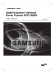
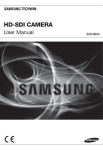
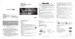
High Resolution Day & Night Varifocal Lens Camera SOC-4160 User Guide
Before installing and operating this product,
please read this manual thoroughly.
ENGLISH
Before operating the camera, confirm the camera model and correct input power
voltage. In order to that you can understand this manual thoroughly, we will explain the
model description.
n SOC-4160 SERIES
• NTSC MODEL
SOC-4160N
• PAL MODEL
SOC-4160P
n MODEL DESCRIPTION
• SOC-4160 X_
SIGNAL SYSTEM
• SIGNAL SYSTEM
N --> NTSC MODEL
P --> PAL MODEL
The lightning flash with an arrowhead symbol, within an equilateral triangle is
intended to alert the user to the presence of uninsulated “dangerous voltage”
within the product's enclosure that may be of sufficient magnitude to constitute
a risk of electric shock to persons.
The exclamation point within an equilateral triangle is intended to alert the user
to the presence of important operating and maintenance (servicing) instructions
in the literature accompanying the appliance.
INFORMATION -This equipment has been tested and found to comply with limits
for a Class A digital device, pursuant to part 15 of the FCC Rules. These limits are
designed to provide reasonable protection against harmful interference when the
equipment is operated in a commercial environment. This equipment generates,
uses, and can radiate radio frequency energy and, if not installed and used in
accordance with the instruction manual, may cause harmful interference to radio
communications.
Operation of this equipment in a residential area is likely to cause harmful
interference in which case the user will be required to correct the interference at
his own expense.
WARNING - Changes or modifications not expressly approved by the manufacturer
could void the user’s authority to operate the equipment.
WARNING - To prevent electric shock and risk of fire hazards:
◆ Do NOT use power sources other than that specified.
This installation should be made by a qualified service person and
should conform to all local codes.
Contents
Contents
Features
• Features………………………………………………………………… 5
• Warnings & cautions…………………………………………………… 6
• Precautions…………………………………………………………… 7
• Components and Accessories………………………………………… 9
• Overview………………………………………………………………… 9
■ Front……………………………………………………………………………… 9…
■ Back……………………………………………………………………………… 10
• Adjust to lens…………………………………………………………… 11
■ Adjust to Lens’s ZOOM and Focus……………………………………………… 11
• Connection……………………………………………………………… 12
■ Connecting to monitor… ……………………………………………………… 12…
■ Connecting to power…………………………………………………………… 13…
■ RS-485 Communication control… …………………………………………… 14
■ Using Coaxial Communications………………………………………………… 15
• Operating Your Camera… …………………………………………… 16
■ Menu Configuration… ………………………………………………………… 16…
■ Menu Setup……………………………………………………………………… 16…
• LENS (Adjusting to the brightness level)……………………………………
• EXPOSURE… ……………………………………………………………
• White Balance (White Bal.)…………………………………………………
• SSDR (Samsung Super Dynamic Range)……………………………………
• BACKLIGHT………………………………………………………………
• SSNR3……………………………………………………………………
• DAY/NIGHT… ……………………………………………………………
• SPECIAL… ………………………………………………………………
• EXIT………………………………………………………………………
17…
18…
19…
20…
21…
23…
24…
26…
31
• Troubleshooting………………………………………………………… 32
• Specifications…………………………………………………………… 33
• Dimension……………………………………………………………… 34
COLOR CCD CAMERA
4
User Guide
Excellent Sensitivity
DIS (Digital Image Stabilizer)
The built-in high sensitivity COLOR CCD enable a
clear image even in 0.15Lux(COLOR), 0.0003Lux
(SENS-UP) or lower illumination.
The DIS function compensates for any camera
movement, to produce more stable pictures.
IP66 Approved/Dust and Rain
Resistant
High Resolution
By adopting a diagonal 6mm(1/3") 410,000 (NTSC)
pixel, 470,000(PAL) pixel SONY CCD, the camera
produces clear picture quality with a horizontal
resolution of 600 TV lines for color and a horizontal
resolution of 700TV lines for BW mode.
SSNR3 (Samsung Super Noise
Reduction) Function
The high-performance W-V DSP chip effectively
removes low-light gain noise and ghosting to
provide clear images even in dark environments.
With dust and rain resistant design, the camera
can be installed outside under building eaves or
places that are exposed to the dust and rain.
Communication
RS-485, Coaxial communication methods are
supported.
-RS-485 Communications
: STW(SPD), PELCO-P, PELCO-D, VICON, PANASONIC,
BOSCH, HONEYWELL, SEC
-Coaxial Communications
: Pelco Coaxition
DAY&NIGHT(ICR)
This camera has a function that automatically
selects the mode that is appropriate for daytime or
night-time conditions.
The COLOR mode operates in daytime conditions
to provide optimum colors, and BW mode operates
in night-time conditions to enhance the definition
of the image.
SSDR
(Samsung Super Dynamic Range)
For images with high contrast between bright and
dark Areas from difficult lighting conditions such
as backlighting, this camera selectively illuminates
darker Areas while retaining the same light level
for brighter Areas to even out the overall brightness.
COLOR CCD CAMERA
Miscellaneous Functions
HLC(High Light Compensation), SENS-UP, FLIP(H/
V-REV), D-ZOOM, SHARPNESS, MOTION DETECTION
and PRIVACY functions are provided.
OSD
The camera’s OSD is complimented by 18 languages.
- NTSC: Korean, English, French, Spanish,
Japanese, Portuguese, Taiwanese
- PAL : English, French, German, Spanish, Italian,
Chinese, Russian, Czech, Polish, Romanian,
Serbian, Swedish, Danish, Turkish, Portuguese
5
User Guide
Precautions
Samsung Techwin cares for the environment at all product manufacturing stages to preserve
the environment, and is taking a number of steps to provide customers with more
environment-friendly products. The Eco mark represents Samsung Techwin's will to create
environment-friendly products, and indicates that the product satisfies the EU RoHS Directive.
Warnings & Cautions
Do not install under extreme
temperature conditions.
Do not install in high humidity
environment.
This information is provided to ensure your safety and to prevent any losses, financial or
otherwise. Please read it carefully and use the product accordingly.
* For product inquiries, please contact the retail shop where you bought the camera. The use of
equipment such as an aerial ladder while providing after-sales service shall be at your expense.
Notes
• Please make sure the product is installed appropriate places where secured from
flood, such as under the eaves, to operate properly.
• This product is certified as IP66 standard. However, if there is any flood concerns, it
is highly recommended to use an outdoor Housing When you install the camera
inside an outdoor Housing, please use one of the following methods:
1. Remove the front glass of Housing before installing the camera.
2. To keep the front glass of Housing, remove the front cover, and then put the
camera close to the front glass.
Use only under temperature conditions
between -10°C and +50°C. Provide
good ventilation when using in high
temperature conditions.
May lower image quality.
Warning/Attention/Special Mark Messages
Ignoring this information may result in
death or or serious personal injuries.
Ignoring this information may result in
material loss or personal injuries.
Indicates "Never Allowed."
Indicates "No Disassembling."
Do not install under unstable
lighting conditions.
Severe lighting changes or flickering may
hinder normal camera operation.
COLOR CCD CAMERA
6
User Guide
Avoid touching the camera lens.
The lens is the most important component
of the camera. Be careful not to smear it
with fingerprints.
COLOR CCD CAMERA
7
User Guide
Components and Accessories
Precautions
Do not drop the camera or
subject it to physical shock.
Never keep the camera face to
strong light directly.
❶
2
3
❹
➎
❻
0
SOC-416
7
❶ SOC-4160
2 Sunshield
3 L-type hexagon wrenches (3.0mm)
4 Sunshield Adaptor (1EA) 5 Tapping Screw (3EA) ❻ User’s Manual
7 Installation Video Output Cable May cause a product malfunction.
Overview
May damage the CCD.
FRONT
Do not expose the camera to
radioactivity.
2
❶
3
4
5
Radioactivity exposure may damage the
CCD.
7
Notes
• Exposure to a spotlight or an object emitting strong light may cause smear or
blooming.
• Ensure that the power source complies with normal specifications before
supplying it to the camera.
COLOR CCD CAMERA
8
User Guide
❶ Camera Sunshield
2 Sunshield adaptor : Fixing the sunshield onto the camera.
3F
ocus lever : Set focus of lens by turn the focus lever.
4Z
oom lever : Set zoom magnification of lens by turn the zoom lever.
5F
ront cover
6F
unction Setup Switch :
6
Display the menu on the screen and move the cursor to four directions to confirm
status or after changing a selected item.
➐V
ideo Output Terminal to Monitor :
Used for monitoring of video output When camera installation.
COLOR CCD CAMERA
9
User Guide
Adjust to Lens
Overview
Adjust the lens's zoom and focus.
Notes
• When you adjust to the ZOOM & FOCUS of the lens, Please remove the front cover
from the camera, by turning the cover counterclockwise.
• To adjust the zoom & focus loosen the individual levers before tightening them
again.
• To ensure the weatherproof integrity is maintained, ensure the front cover is
tightened correctly.
BACK
1. Remove the sunshield from the camera.
2. Remove the front cover from the camera by turning it counterclockwise.
3. Unlock the Zoom or Focus lever before adjusting the lens.
4.Adjust the zoom & focus by moving the lever counterclockwise for (NEAR & TELE)
and clockwise for (WIDE & FAR) position.
5.After adjustment, tighten the zoom or focus levers, taking care not to adjust the
zoom/focus position.
6. Please, close and tighten the front cover.
7.Replace the sunshield.
SOC-4160
Front cover
ZOOM lever
SOC-4160
8
Focus lever
❿
9
❽P
ower input terminal : Connect the power as specified for each model here.
9 Video output terminal : V
ideo signals are output through this port. Connect
this port to the Video IN port of a monitor.
❿R
S-485 control terminal :
You can control SETUP MENU through this port by using external controllers like a
Remote controller that RS-485 Communication is supported. For details, see page 14.
COLOR CCD CAMERA
10 User Guide
Notes
• If the front cover is cross threaded or not correctly tightened the camera housing
will not be weatherproof.
• When you combine the front cover, combine the triangle of front cover and triangle
of main body confront each other.
COLOR CCD CAMERA
11 User Guide
Connection
Connecting to Power
Connecting to Monitor
Please connect the video output terminal located on the back of the camera to the
monitor.
Monitor
The recommended adaptor specification for SOC-4160N/P is DC 12V/ 500mA ,
AC 24V / 500mA.
Please check the standard power requirement before connecting the power.
Recommend AC24A / 500mA adaptor for a long-distance.
CCD Camera
• The connection method varies depending on the type of monitor and accessories.
Please refer to the user's manual for each instrument.
• Please turn off the power when connecting.
• Please select Hi-Z on the 75Ω/Hi-Z switch for the intermediate video TV set and
select 75Ω for the Intermediate device as shown in the picture below.
Intermediate
CCD Camera
End monitor
When the resistance value of copper wire is at [20°C(68°F)]
Copper wire size(AWG)
#24(0.22mm2)
#22(0.33mm2)
#20(0.52mm2)
#18(0.83mm2)
Resistance value(Ω/m)
0.078
0.050
0.030
0.018
Voltage drop(V/m)
0.028
0.018
0.011
0.006
• As shown in the table above, voltage decreases as the wire gets longer.
Therefore having an excessively long distance between the power adaptor and the
camera may affect the camera's performance.
✽ Standard voltage for camera operation : DC 12V±10% / AC 24V±10%
✽ There may be some deviation in voltage drop depending on the type of wire and the manufacturer.
Notes
• Please use a power adaptor that meets the required standards.
• Please connect the power after installation.
COLOR CCD CAMERA
12 User Guide
COLOR CCD CAMERA
13 User Guide
Connection
RS-485 communication control
Using Coaxial Communications
•C
oaxial Communications System
• OSD Control method
Connecting to RS-485 Control Cable
WHITE (TRX+)
BLACK (TRX-)
CONTROL CABLE
SPEC
WHITE (TRX+)
RS-485+
BLCAK (TRX-)
RS-485-
Using RS-485 communication will enable you to control the OSD menu from a SAMSUNG
TECHWIN System Controller or DVR.
(1) Connection to a PC.
Connect the camera to the PC via a RS-485 converter using RS-485 and a serial cable.
CAMERA
DVR
CONTROLLER
SET
UP
DOWN
LEFT
RIGHT
MENU/ENTER
UP KEY
DOWN KEY
LEFT KEY
RIGHT KEY
OSD KEY
JOYSTICK UP
JOYSTICK DOWN
JOYSTICK LEFT
JOYSTICK RIGHT
DVR
DVD
EX) SERIAL PORT OF THE PC(COM1) → SERIAL CABLE → RS-485 CONVERTER → RS-485
CONTROL CABLE
0
SOC-416
(2) Connection to a DVR or System Controller.
Connect the RS-485 cable to the connection ports of the DVR or System Controller.
485 Control Board Connection Port
RS-485 Control Port
(+) CONNECTION TERMINAL
(-) CONNECTION TERMINAL
WHITE (TRX+)
BLACK (TRX-)
* RS-485 Communication establishment initial value
Item
Initial value
Camera ID
BAUD RATE
UART MODE
RET PKT
1
9600
8-NONE-1
ENABLE
• : BNC
• ----: RS-485
– Video Cable
The camera's video output port is connected to the monitor with a BNC coaxial cable,
shown below : If the distance between the camera and the monitor exceeds the
recommended maximum, please use an auxiliary video amp.
Distance
300m
450m
600m
Notes
• When making a control system to control the camera, please use to the
protocol(STW(SPD), PELCO-P, PELCO-D, VICON, PANASONIC, BOSCH, HONEYELL, SEC).
• When you connecting to RS-485 CONTROL TERMINAL, please peel off the outer
skin inside the RS-485 CONTROL TERMINAL.
• In case of SCC-101 connection, change communication mode to『8-E-1』at『Communication
configuration』menu. (For more information, refer to SCC-101 manual.)
COLOR CCD CAMERA
14 User Guide
Recommended Cable Specification
3C2V(RG-59/U)
5C2V(RG-6/U)
7C2V(RG-11/U)
Notes
• If the camera is controlled through coaxial communication, please use a video amp
intended for coaxial communications. Regular video amps do not transfer coaxial
signals.
COLOR CCD CAMERA
15 User Guide
Operating Your Camera
Menu Configuration
Select the function using
the Function Setup switch.
MAIN SETUP
LENS
EXPOSURE
WHITE BAL
SSDR
BACKLIGHT
SSNR3
DAY/NIGHT
SPECIAL
EXIT
●DC
●BRIGHTNESS ●SHUTTER
●SENS-UP
●RETURN
●ATW
●OUTDOOR
●MANUAL
●AWC→SET
●OFF
●ON
●OFF
●BLC
●OFF
●ON
●COLOR
●B/W
●IMAGE ADJ. ●CAM TITLE
●MOTION DET ●PRIVACY
●COMM ADJ ●LANGUAGE
●SAVE
●NOT SAVE
Menu Setup
Use the Function Setup Switch whitin the camera.
●AGC ●INDOOR
●HLC
●AUTO
●SYNC
●DIS
●RETURN
●RESET
MAIN SETUP
1.LENS
DC
2.EXPOSURE 3.WHITE BAL
ATW
4.SSDR OFF
5.BACKLIGHT
OFF
6.SSNR3
ON
7.DAY/NIGHT
AUTO
8.SPECIAL 9.EXIT
SAVE
Change the status using
the Function Setup switch.
2. Select a desired function using the Function Setup switch.
• Place the cursor over a desired item.
3. Set up a selected item by using the Function Setup switch.
4. To finish the setting, select ‘EXIT’ and press the Function Setup switch.
Notes
• An item with the
icon also has sub menus. To select a sub menu, select an item with
the icon and press the Function Setup switch.
• An item with the - - - icon is unavailable due to function settings.
LENS
Using this function, you can control the screen brightness.
1. When the SETUP menu screen is displayed, select‘LENS’by using the Function Setup
switch so that the arrow indicates‘LENS’.
2. DC : You can adjust the minimum shutter and maximum value of ESC shutter mode.
MAIN SETUP
1.LENS
2.EXPOSURE 1. Press the Function Setup switch.
• Main setup menu is displayed on the monitor screen.
COLOR CCD CAMERA
16 User Guide
DC
3. THE Lens mode has sub menu items as listed below.
- BRIGHTNESS : Adjusts the video brightness.
COLOR CCD CAMERA
17 User Guide
Operating Your Camera
Notes
- FOCUS ADJ : To adjust the DC lens focus correctly, you must activate the Focus Settings
mode under each lens menu. Activate the Focus Settings mode, adjust
the lens focus, and then deactivate the settings mode.
Notes
• If color rolling occurs when using a DC lens, set Shutter to Fixed (---).
EXPOSURE
MAIN SETUP
1.LENS
2.EXPOSURE 3.WHITE BAL
DC
ATW
1. When the SETUP menu screen is displayed, select 'EXPOSURE' by using the Function
Setup Switch.
2. Select a desired mode using the Function Setup switch.
EXPOSURE SETUP
• When the SHUTTER is set to MANUAL or A.FLK mode, SENS-UP will be disabled.
1.BRIGHTNESS
2.SHUTTER
3.AGC
4.SENS-UP
5.RETURN
25
--HIGH
OFF
SHUTTER
: You can select either auto or manual shutter.
- --- : Shutter speed is fixed at 1/60sec(1/50sec)
- ESC : Select this to control the shutter speed automatically. If ESC is selected, the
shutter speed is automatically controlled depending on the ambient
illumination of the subject.
- MANUAL : You can control shutter speed manually.
(NTSC MODEL : 1/60~1/120,000, PAL MODEL : 1/50~1/120,000)
- A.FLK : Select this when you see picture flicker, this can happen when the frequency
of the local lighting clashes with the camera.
COLOR CCD CAMERA
18 User Guide
AGC(AUTO GAIN CONTROL) : The higher the gain level, the brighter the screen - but
the higher the noise.
- OFF : Deactivates the AGC function.
- LOW : Allows automatic gain control from 5.3dB to 32dB.
- HIGH : Allows automatic gain control from 5.3dB to 37dB.
SENS-UP : When it is night or dark, the camera automatically detects the light level
and maintains a clear picture if this mode is activated.
- OFF : Deactivates the SENS-UP function.
- AUTO: Activates the SENS-UP function.
RETURN : Select this to save the changes in the EXPOSURE menu and return to the
SETUP menu.
Notes
• If you press the Function Setup switch to ‘AUTO’ mode, you can adjust brightness by increasing or
decreasing the shutter speed. (x2 ~ x512)
• Note that the higher the zoom level, the brighter the screen, but the more likely there will be a
ghosting effect.
• It is normal for Noise, Spots and Whitish symptoms to appear in SENS-UP mode when the
D-ZOOM level is increased.
White Balance (White Bal)
Use the White Balance function to adjust the screen color.
1. When the SETUP menu screen is displayed, select ‘White Bal’ by using the Function
Setup switch so that the arrow indicates ‘White Bal’.
2. Select a desired mode using the Function Setup switch.
MAIN SETUP
1.LENS
DC
2.EXPOSURE 3.WHITE BAL
ATW
4.SSDR OFF
COLOR CCD CAMERA
19 User Guide
Operating Your Camera
※ Select one of the following 5 modes, as appropriate for your purpose.
ATW : Select this when the color temperature is between 1,700˚K and 11,000˚K.
OUTDOOR : Select this when the color temperature is between 1,700˚K and 11,000˚K.
(sodium light inclusion)
INDOOR : Select this when the color temperature is between 4,500˚K and 8,500˚K.
MANUAL : Select this to fine-tune White Balance manually. Set White Balance first
by using the ATW or AWC mode. After that switch to MANUAL mode,
fine-tune the White Balance and then press the Function Setup switch.
AWC →SET : To find the optimal luminance level for the current environment, point
the camera towards a sheet of white paper and press the Function Setup
switch. If the environment changes, readjust it.
1. When the SETUP menu screen is displayed, select ‘SSDR’ by using the switch so that
the arrow indicates ‘SSDR’.
2. U
se the switch to change the SSDR level according to the contrast between bright
and dark areas.
SSDR ON
Notes
• White Balance may not work properly under the following conditions. In this case
select the AWC mode.
❶ When the color temperature of the environment surrounding the subject is out
of the control range (e.g. clear sky or sunset).
2 When the ambient illumination of the subject is dim.
3 If the camera is directed towards a fluorescent light or is installed in a place
where illumination changes dramatically, the White Balance operation may
become unstable.
SSDR (Samsung Super Dynamic Range)
SSDR illuminates darker spots of an image while retaining the same light level for brighter
spots to even out the overall brightness of images with high contrast between bright and
dark spots.
MAIN SETUP
1.LENS
DC
2.EXPOSURE 3.WHITE BAL
ATW
4.SSDR OFF
5.BACKLIGHT
OFF
COLOR CCD CAMERA
20 User Guide
SSDR OFF
BACKLIGHT
Unlike conventional cameras, the SOC-4160 is designed to deliver a distinctive subject and
background at the same time, even when the subject is backlight, by using the features of
the proprietary W-V DSP chip.
1. When the SETUP menu screen is displayed, select ‘BACKLIGHT’ by using the Function
Setup switch so that the arrow indicates ‘BACKLIGHT’.
MAIN SETUP
1.LENS
2.EXPOSURE 3.WHITE BAL
4.SSDR 5.BACKLIGHT
DC
ATW
OFF
OFF
2. Select a desired mode using the Function Setup switch.
BLC : Enables a user to directly select a desired area from a picture, and to view the
area more clearly.
COLOR CCD CAMERA
21 User Guide
Operating Your Camera
HLC (High Light Compensation) : If the scene contains extremely bright light areas such as; from car headlights, the
light can mask out much of the on-screen detail.
- LEVEL : Adjust level of the HLC function.
- LIMIT : Enable to change the operating condition.
- MASK COLOR/TONE : Change the color / transparency of the masking area.
(Black, Red, Blue, Cyan, Magenta)
- TOP/BOTTOM/LEFT/RIGHT : Adjust the area to be enhanced
SSNR3
This function reduces the background noise in a low luminance environment.
1. When the SETUP menu screen is displayed, select ‘SSNR3’ by using the Function
Setup switch so that the arrow indicates ‘SSNR3’.
MAIN SETUP
1.LENS
DC
2.EXPOSURE 3.WHITE BAL ATW
4.SSDR OFF
5.BACKLIGHT OFF
6.SSNR3
ON
7.DAY/NIGHT AUTO
OFF : Not being used
3. Select a desired mode using the Function Setup switch and press the Function Setup switch.
Select ‘BLC’ to adjust the area to be
HLC : E nable the user to change the level,
enhanced then adjust the level.
limit, mask color/tone and area.
LOW
2. Select a desired mode using the Function Setup switch.
OFF: Deactivates SSNR3. Noise is not reduced.
ON: Activates SSNR3 so that noise is reduced.
3. Set the SSNR3 mode to ‘ON’ and press the Function Setup switch. Then you can
adjust the noise reduction level.
Notes
Notes
• Because there can be a difference in the effectiveness of HLC according to the amount of
light area in the screen, optimize the installation angle for the best HLC performance.
• When dark, the HLC is only activated when a bright light exceeding a specific size in
NIGHT ONLY mode.
• The HLC is not activated in day light or when bright light is not present at night in NIGHT
ONLY mode.
COLOR CCD CAMERA
22 User Guide
• You cannot set the SSNR3 to ‘ON’ or ‘OFF’ when the AGC mode of the
EXPOSURE menu is ‘OFF’.
• When adjusting the noise reduction level in the SSNR3 mode, remember that
the higher the level set, the more the noise level will be reduced, as will the
brightness of the image.
COLOR CCD CAMERA
23 User Guide
Operating Your Camera
DAY/NIGHT
You can display pictures in color or black and white.
1. When the SETUP menu screen is displayed, select ‘DAY/NIGHT’ by using the Function
Setup switch so that the arrow indicates ‘DAY/NIGHT’ .
- BURST MODE : You can turn on or off the burst signal on
B/W mode.
- DURATION : You can select brightness of illumination
about changing the day/night mode.
- DWELL TIME : You can select the duration time about
changing the day/night mode. …
→3s, 5s, 7s, 10s, 15s, 20s, 30s, 40, 60s
MAIN SETUP
1.LENS DC
2.EXPOSURE 3.WHITE BAL
ATW
4.SSDR
OFF
5.BACKLIGHT
OFF
6.SSNR3
ON 7.DAY/NIGHT
AUTO
8.SPECIAL Fast
Slow
Color → B/W
2.5 lux
1 lux
B/W → Color
5 lux
10 lux
24 User Guide
FAST
10SEC
• When AGC in the EXPOSURE menu is 'OFF', '---' mode operates as like selecting 'COLOR'
mode and 'AUTO' mode can not be selected.
B/W MODE SETUP
▶1.BURST MODE
2.RETURN
ON
AUTO : The mode is switched to ’Color‘ in a normal environment, but switches to ’B/
W‘ mode when ambient illumination is low. To set up the switching time for
AUTO mode, press the Function Setup switch. You can turn on or off the burst
signal on B/W mode.
COLOR CCD CAMERA
ON
FAST
3SEC
Notes
COLOR : The picture is always displayed in color.
AUTO SETUP
▶1.BURST MODE
2.COLOR→B/W
DURATION
DWELL TIME
3.B/W→COLOR
DURATION
DWELLTIME
4.RETURN
* The day/night switching point of the camera
can be adjusted.
2. S elect a desired mode using the Function Setup Switch according to the picture display
you want.
B/W : T he picture is always displayed in black and white.
- BURST MODE : You can turn on or off the burst signal on
B/W mode.
COLOR CCD CAMERA
25 User Guide
Operating Your Camera
SPECIAL
1. When the SETUP menu screen is displayed, select ‘SPECIAL’ by using the Function Setup
switch so that the arrow indicates ‘SPECIAL’.
MAIN SETUP
1.LENS
DC
2.EXPOSURE 3.WHITE BAL ATW
4.SSDR OFF
5.BACKLIGHT OFF
6.SSNR3
ON
7.DAY/NIGHT AUTO
8.SPECIAL 9.EXIT SAVE
2. Select a desired mode using the Function Setup switch.
1.
2.
3.
4.
5.
6.
7.
8.
9.
SPECIAL
IMAGE ADJ CAM TITLE
SYNC
MOTION DET
PRIVACY
DIS
COMM ADJ
LANGUAGE
RETURN
OFF
INT
OFF
OFF
OFF
ENGLISH
IMAGE ADJ. :
1) When the SETUP menu screen is displayed, select ‘IMAGE ADJ’ by using the Function
Setup switch so that the arrow indicates ’IMAGE ADJ‘.
2) Select a desired mode using the Function Setup switch.
IMAGE SETUP
1.V-REV
OFF
2.H-REV
OFF
3.D-ZOOM
OFF
4.FONT COLOR
WHITE
5.SHARPNESS
ON
6.MONITOR LCD
7.RETURN
• V-REV : You can flip the picture vertically on the screen.
• H-REV : You can flip the picture horizontally on the screen.
• D-ZOOM : You can use a digital zoom of x1 ~ x16.
• FONT COLOR : You can change the OSD font color. (White, Yellow, Green, Red, Blue)
• SHARPNESS : As you increase this value, the picture outline becomes stronger and
clearer. Adjust this value appropriately depending on the sharpness of
the picture.
• MONITOR : Please change the settings value of video
appropriate to your monitor.
- LCD : Please select this menu item when using a LCD
monitor.
- CRT : Please select this menu item when using a CRT
monitor.
- USER : Please use this menu item when using a monitor other than standard ones. You
can change the gamma, PED level, and color gain in the sub menus.
• RETURN : Select this to save the settings for the IMAGE ADJ menu and to return to
the SETUP menu.
Notes
• When the V-REV or H-REV mode is enabled, the text on the screen does not flip.
• If you increase the SHARPNESS level too high, the picture may become distorted
or noise may appear.
COLOR CCD CAMERA
26 User Guide
COLOR CCD CAMERA
27 User Guide
Operating Your Camera
CAM TITLE : If you enter a title, the title will appear on the monitor.
1) If the SPECIAL menu screen is displayed, use the Function Setup switch so that the
arrow indicates ‘CAM TITLE’.
2) Set it to ‘ON’ by using the Function Setup switch. CAMERA TITLE SETUP
ABCDEFGHIJKLM
3) Press the Function Setup switch.
NOPQRSTUVWXYZ
abcdefghijklm
4) Use
the Function Setup switch to move to
nopqrstuvwxyz
a desired letter and select the letter by
-.0123456789
pressing the Function Setup switch.
←→CLR POS END
Repeat this to enter multiple letters. You
can enter up to 15 letters.
5) Enter
a title, move the cursor to ‘POS’ and
press the Function Setup switch. The
FRONT DOOR
entered title appears on the screen. Select
the position to display the title on the
screen by using the Function Setup switch
and press the Function Setup switch.
When the position is determined, select
‘END’ and press the Function Setup switch
to return to the SPECIAL menu.
SYNC : In areas where the supply is at 60Hz(NTSC),
50Hz(PAL), you can synchronize the output phase
of multiple cameras using the power
synchronization function (Line-Lock) without using
a synchronization signal generator.
- INT : Internal Synchronization Type
- L/L : Power Synchronization Type, Line-lock
• Press the Function Setup switch.
• You can select a desired phase from 0 to 359 when select 'phase'.
Notes
• When using AC power at 60Hz(NTSC), 50Hz(PAL), frequency, you can use the L/L
type synchronization.
• When the power is DC 12V, the SYNC menu is fixed to the ‘INT’ mode.
MOTION DET : This product has a feature that allows you to observe
movement of objects in 8 different areas on the screen,
and the words 'MOTION DETECTED' appear on the screen
when movement is detected.
Activity can be monitor more efficiently.
1) When the SPECIAL menu screen is displayed, press the
Function Setup switch so that the arrow indicates‘MOTION DET’.
2) Set
up the mode using the Function Setup switch.
Notes
• When the CAM TITLE menu is ‘OFF’, no title will be displayed on the monitor screen
even if you enter one.
• Only English is available in this mode.
• If you move the cursor to CLR and press the Function Setup switch, all the letters
are deleted. To edit a letter, change the cursor to the bottom left arrow and press
the Function Setup switch. Move the cursor over the letter to be edited, move the
cursor to the letter to be inserted and then press the Function Setup switch.
COLOR CCD CAMERA
28 User Guide
- SENSITIVITY : You can select up to 8 MD areas. When SENSITIVITY number is high, motion
detection sensitivity is increased to recognize even small movement.
- AREA MODE : Determines whether to use the MD area selected in SENSITIVITY.
- SEL POS : Determines which of the 4 vertices of each MD area is to be used.
- XPOS : Determines the coordinate of the horizontal axis for SEL POS.
- YPOS : Determines the coordinate of the vertical axis for SEL POS.
- FILL→SET : Fills in a selected MD area. The color of the area can be selected from
brown, orange, blue, cyan, green, yellow, magenta and red.
- RETURN : Select this to save the MOTION DET menu settings and return to the SPECIAL menu.
COLOR CCD CAMERA
29 User Guide
Operating Your Camera
PRIVACY :Mask an area you want to hide on the screen.
PRIVACY AREA SETUP
1.AREA
AREA1
2.MODE
OFF
3.MASK COLOR
GREEN
4.MASK TONE
1
5.TOP
39
6.BOTTOM
79
7.LEFT
13
8.RIGHT
52
9.RETURN
COMM ADJ (Communication Adjustment) :
This function sets up the camera communication status when controlling the camera
through an external control device.
1) When the SPECIAL menu screen is displayed, press the Function Setup switch
so that the arrow indicates ‘COMM ADJ’.
2) Set up the mode using the Function Setup witch.
- CAM ID : Determines the camera's identification
number (between 0 and 255).
- BAUD RATE : You can select 2400/4800/9600/19200
/38400/57600 bps.
- UART MODE : You can select NONE, EVEN or ODD
for the parity bits.
- RET PKT : Determines whether to send a command
back to the controller device when a
communication control command is sent to the camera.
- DISP ID : Display camera title on top left corner of the screen.
- PROTOCOL : You can select one of various protocols. STW(SPD), PELCO-P, PELCO-D,
VICON, PANASONIC, BOSCH, HONEYWELL, SEC.
1) When the SPECIAL menu screen is displayed, press the Function Setup switch so
that the arrow indicates ‘PRIVACY’.
2) Set up the mode using the Function Setup switch.
- AREA : You can select up to 12 PRIVACY areas.
- MODE : Determines whether to use the area selected in the AREA.
- MASK COLOR :Determine area color. You can select Green, Red, Blue, Black, White, Gray.
- MASK TONE : Adjust the brightness of MASK COLOR.
- TOP/BOTTOM/LEFT/RIGHT : Adjust the size and position of the selected area.
- RETURN : Select this to save the PRIVACY menu settings and return to the SPECIAL menu.
DIS (Digital Image Stabilizer) :
This function mitigates any picture movement due to external factors such as wind.
* Initial value of communication adjustment
Item
Initial value
Camera ID
1
BAUD RATE
9600
UART MODE
8-NONE-1
PET PKT
ENABLE
LANGUAGE: You can select the menu language according to your requirements.
RETURN : Select this to save the SPECIAL menu settings and return to the MAIN
SETUP menu.
EXIT
Notes
• As the DIS function uses the digital zoom the camera's resolution will decrease.
• DIS doesn’t operate when background illumination is too low.
• DIS doesn’t operate when object pattern is monotonic as like sky or white wall.
COLOR CCD CAMERA
30 User Guide
Select a desired EXIT mode using the Function Setup Switch.
- SAVE
: Save the current settings and exit the MAIN SETUP menu.
- NOT SAVE : Do not save the current settings and exit the MAIN SETUP menu.
- RESET
: Resets the camera settings to the factory defaults. Language, Communication
and Monitor settings are not initialized.
COLOR CCD CAMERA
31 User Guide
Troubleshooting
If there are problems in operation, please refer to the items below. If the
problem persists, please contact the agent you purchased this product from.
• Nothing appears on the screen.
▶ Check that the power cord and line connection between the camera and monitor are
fixed properly.
▶ Check that you have properly connected UTP cable or BNC cable to the camera.
• The image on the screen is dim.
▶ Is lens stained with dirt? Clean your lens with soft, clean cloth.
▶ Set the monitor to proper condition.
▶ If the camera is exposed to too strong light, change the camera position.
• The image on the screen is dark.
▶ Adjust the contrast feature of the monitor.
▶ If you have an intermediate device, set the 75Ω / Hi-z properly.
• The camera is not working properly, and the surface of the camera is hot.
▶ Check that you have properly connected the camera to an appropriate power source.
• The SENS-UP function does not work.
▶ Check that AGC of EXPOSURE SETUP menu is ‘OFF’.
▶ Check that SHUTTER of EXPOSURE SETUP menu is ‘A.FLK’ or ‘MANUAL’.
• The Motion Detection function does not work.
▶ Check that MOTION DET of SPECIAL SETUP menu is ‘OFF’.
• Color is not correct.
▶ Check the setting of WHITE BAL SETUP menu.
• The screen flickers continually.
▶ Check that direction of camera turns toward the Sun.
• When coaxial communication is not available:
▶M
ake sure that the camera and monitor are installed within the recommended distance.
▶U
se the video amplifier equivalent to coaxitron if the recommended installation distance is
exceeded.
• When the camera is not waterproof.
▶ Please check the Front Cover and Main Body by the following Guide Label.
COLOR CCD CAMERA
32 User Guide
Specifications
SOC-4160N
ELECTRICAL
Input Voltage
Power Consumption
VIDEO
Imaging Device
Total Pixels
Effective Pixels
Scanning System
Synchronization
Frequency
Horizontal Resolution
Min. Illumination
S/N (Y Signal)
Video Output
LENS
Zoom Ratio
Focus Length
Angular Field of View
OPERATIONAL
Electronic Shutter Speed
On Screen Display
SSDR
Backlight Compensation
Day & Night
Gain Control
White Balance
SENS-UP (frame Integration)
Motion Detection
Privacy Masking
3D Noise Filter (SSNRIII)
Digital Zoom
Digital Image Stabilization(DIS)
Camera Title
Sharpness
Flip / Mirror
Communication
Protocol
ENVIRONMENTAL
Operating Temperature / Humidity
Storage Temperature / Humidity
MECHANICAL
Water Resistance
Dimension
Weight
SOC-4160P
DC 12V / AC 24V
MAX 2.7W / 3.8W
1/3 inch, Diagonal 6mm Super HAD CCD
811(H) x 508(V)
795(H) x 596(V)
768(H) x 494(V)
752(H) x 582(V)
2:1 Interlace
Internal /Line-Lock
H : 15.734KHz V:59.94Hz
H: 15.625KHz V: 50.00Hz
COLOR : 600TVL, B/W : 700TVL
COLOR : 0.15Lux (50IRE, @F1.2), 0.0003Lux (SENE-UP, x512)
B/W : 0.001Lux (50IRE, @F1.2), 0.000002Lux (SENS-UP, x512)
52dB (Weight On, AGC Off)
CVBS : 1.0Vp-p, 75Ω composite
3.6x (Manual)
2.8 ~ 10.0mm (F1.2)
H : 94.4°(Wide)~28°(Tele) / V : 69.2°(Wide)~21°(Tele)
1/60 ~ 1/120k sec
1/50 ~ 1/120k sec
NTSC : 7 Languages, PAL : 15 Languages
On / Off (Level adjustable)
BLC / HLC / OFF
COLOR / B/W / AUTO (ICR)
Low / High / Off
ATW / Outdoor / Indoor / Manual / AWC (1,700°K ~ 11,000°K)
Auto / Off (Selectable x2 ~ x512)
On / Off (8 Programmable zones)
On / Off (12 Programmable zones)
On / Off (Level adjustable)
On / Off (x1 ~ x16)
On / Off
On / Off (Displayed 15 Characters)
On / Off (Level adjustable)
On / Off
Coaxial, RS-485
Coaxial(Pelco), RS-485(STW(SPD), PELCO-P, PELCO-D, VICON, PANASONIC,
BOSCH, HONEYWELL, SEC)
-10°C ~ +50°C / 30% ~ 80% RH
-20°C ~ +60°C / 20% ~ 90% RH
IP66
Ø77mm(W) x 216mm(H) (BRACKET ANGLE 90°), 284mm (BRACKET ANGLE 180°)
955g
※ The specification for this product may change without prior notice for product improvement.
COLOR CCD CAMERA
33 User Guide
DECLARATION OF CONFORMITY
118.5mm
Dimension
Application of Council Directive(s)
89 / 336 / EEC
Manufacturer's Name SAMSUNG TECHWIN CO., LTD
Manufacturer's Address
SAMSUNG TECHWIN CO., LTD
42, SUNGJU-DONG CHANGWON-CITY,
KYUNGNAM, KOREA, 641-716
European Representative Name
Ø77
86mm
274.7mm
European Representative Address
Equipment Type/Environment CCTV Camera
Model Name SOC-4160P
Beginning Serial NO. C10S8010007
Year of Manufacture 2009.08.01
Conformance to EN 50081-1 : 1992
EMC-Directive 89/336 EEC and 92/31/EEC
EN 50130-4 : 1996
Ø79.8
We, the undersigned, hereby declare that the equipment specified above conforms
to the above Directive(s).
244.7mm
COLOR CCD CAMERA
34 User Guide
Manufacturer SAMSUNG TECHWIN CO., LTD Legal Representative in Europe
Signature Signature
Full Name BONJENG GU
Full Name Position QUALITY CONTROL MANAGER Position Place CHANGWON, KOREA
Place
Date 2009.08.01
Date
COLOR CCD CAMERA
35 User Guide
SALES NETWORK
•
AMSUNG TECHWIN CO., LTD.
S
145-3, Sangdaewon 1-dong, Jungwon-gu, Seongnam-si Gyeonggi-do, Korea, 462-703
TEL : +82-31-740-8151~8 FAX : +82-31-740-8145
•
AMSUNG TECHWIN AMERICA Inc.
S
1480 Charles Willard St, Carson, CA 90746, UNITED STATES
Tol Free : +1-877-213-1222 FAX : +1-310-632-2195
www.samsungcctvusa.com
•
AMSUNG TECHWIN EUROPE CO., LTD.
S
Samsung House, 1000 Hillswood Drive, Hillswood Business
Park Chertsey, Surrey, UNITED KINGDOM KT16 OPS
TEL : +44-1932-45-5300 FAX : +44-1932-45-5325
www.samsungtechwin.com
www.samsungcctv.com
P/No. : Z6806-1045-01B
VAN 09. 10