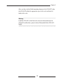
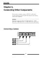
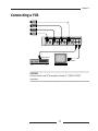
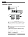
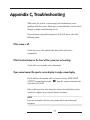
1
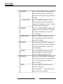
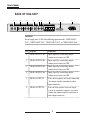
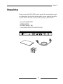
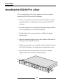
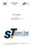
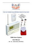
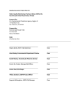
SCQ-041P
User’s Guide
M
ALAR
TUP
EM SE
SYST
ZE
FREE
LE
SING
CHER
AUTO
ER
POW
ON
HE
L
DIGITA QUAD SWITC
R
COLO
R
SWIT
1
3
1
LAY
DISP
2
1 2
3 4
RESET
LIST
Y
SPLA
DI
QUAD
SETUP
ENTER
2
ACTER
CHAR
3 SELECT
4
MENU
4
P
-041
SCQ
OFF
Part No.: AB68-00052A
Printed in Korea
DIGITAL COLOR QUAD
SWITCHER
SCQ-041P
User’s Guide
M
ALAR
TUP
EM SE
SYST
ZE
FREE
LE
SING
CHER
AUTO
ER
POW
ON
HE
L
DIGITA QUAD SWITC
R
COLO
R
SWIT
1
3
1
LAY
DISP
2
1 2
3 4
RESET
LIST
Y
SPLA
DI
QUAD
SETUP
ENTER
2
ACTER
CHAR
3 SELECT
4
MENU
4
P
-041
SCQ
OFF
Part No.: AB68-00052A
Printed in Korea
DIGITAL COLOR QUAD
SWITCHER
SAFETY PRECAUTIONS
WARNING:
To Reduce the risk of fire or electric shock, do not expose this appliance to
rain or moisture.
iii
User’s Guide
IMPORTANT SAFEGUARDS
1. Read instructions: All the safety and operating instructions should
be read before the appliance is operated.
2. Retain instructions: The safety and operating instructions should
be retained for future reference.
3. Heed warnings: All warnings on the appliance and in the operating
instructions should be adhered to.
4. Follow instructions: All operating and use instructions should be
followed.
5. Cleaning: Unplug this video product from the wall outlet before
cleaning. Do not use liquid cleaners or aerosol cleaners. Use a damp
cloth for cleaning.
6. Attachments: Do not use attachments not recommended by the
video product manufacturer as they may cause hazards.
7. Water and moisture: Do not use this video product near water - for
example, near a bath tub, wash bowl, kitchen sink, or laundry tub, in a
wet basement, or near a swimming pool, and the like.
iv
8. Accessories : Do not place this video
product on an unstable cart, stand,
tripod, bracket, or table. The video
product may fall, causing serious injury
to a child or adult, and serious damage
to the appliance. Use only with a cart,
stand, tripod, bracket, or table
recommended by the manufacturer, or
sold with the video product. Any mounting
of the appliance should follow the manufacturer's instructions and
should use a mounting accessory recommended by the manufacturer.
8A.An appliance and cart combination should be moved with care.
Quick stops, excessive force, and uneven surfaces may cause the
appliance and cart combination to overturn.
9. Ventilation : Slots and openings in the cabinet are provided for
ventilation and to ensure reliable operation of the video product and to
protect it from overheating, and these openings must not be blocked or
covered. The openings should never be blocked by placing the video
product on a bed, sofa, rug, or other similar surface. This video product
should never be places near or over a radiator or heat register. This
video product should not be placed in a built-in installation such as a
bookcase or rack unless proper ventilation is provided or the
manufacturer's instructions have been adhered to.
10.Power sources : This video product should be operated only from
the type of power source indicated on the marking label. If you are not
sure of the type of power supply to your home, consult your appliance
dealer or local power company. For video products intended to operate
from battery power, or other sources, refer to the operating instructions.
v
User’s Guide
11.Power-Cord Protection : Power-supply cords should be routed
so that they are not likely to be walked on or pinched by items placed
upon or against them, paying particular attention to cords at plugs,
convenience receptacles, and the point where they exit from the
appliance.
12.Lightning : For added protection for this video product during a
lightning storm, or when it is left unattended and unused for long
periods of time, unplug it from the wall outlet and disconnect the cable
system. This will prevent damage to the video product due to lightning
and power-line surges.
13.Overloading : Do not overload wall outlets and extension cords as
this can result in a risk of fire or electric shock.
14.Object and liquid entry : Never push objects of any kind into this
video product through openings as they may touch dangerous voltage
points or short-out parts that could result in a fire or electric shock.
Never spill liquid of any kind on the video product.
15.Servicing : Do not attempt to service this video product yourself as
opening or removing covers may expose you to dangerous voltage or
other hazards. Refer all servicing to qualified service personnel.
vi
16.Damage requiring service : Unplug this video product from the
wall outlet and refer servicing to qualified service personnel under the
following conditions.
a. When the power-supply cord or plug is damaged.
b. If liquid has been spilled, or objects have fallen into the video
product.
c. If the video product has been exposed to rain or water.
d. If the video product does not operate normally by following the
operating instructions. Adjust only those controls that are covered
by the operating instruction, as an improper adjustment of other
controls may result in damage and will often require extensive work
by a qualified technician to restore the video product to its normal
operation.
e. If the video product has been dropped or the cabinet has been
damaged.
f. When the video product exhibits a distinct change in performance
this indicates a need for service.
17. Replacement parts : When replacement parts are required, be
sure the service technician has used replacement parts specified by the
manufacturer or have the same characteristics as the original part.
Unauthorized substitutions may result in fire, electric shock or other
hazards.
18.Safety Check : Upon completion of any service or repairs to this
video product, ask the service technician to perform safety checks to
determine that the video product is in proper operating condition.
vii
User’s Guide
Prior to Use
This User Guide is the basic guide for users of the SCQ-041P. The
following information includes a product introduction, installation
method, installation with other machines, use of the feature button, and
system management based on the SCQ-041P specification using the
setup menu.
You should read this guide carefully before using the product even if
you have worked with the same level of SCQ-041P to ensure the
products are properly used according to the instructions on the back of
this guide.
It is important to contact the supplier to receive technical assistance
from an expert when you need to open the system cover and work
inside the system to expand or repair the SCQ-041P features.
Also, please contact the product supplier with any questions or if the
product is damaged when using the system.
viii
The Structure of User’s Guide
This guide consists of a total of 6 chapters and 3 appendices. The guide
is necessary to gain a basic understanding of the product and the
intermediate procedures which can be selected according to the user’s
requirements.
To use the SCQ-041P properly, you are advised to read this document
chapter by chapter in order of the contents if possible. The following
quick guide summarizes each chapter:
Chapter 1, “Overview of the SCQ-041P”: Introduces the SCQ-041P
system and describes the features and characteristics of the system as
well as part names and feature buttons.
Chapter 2, “SCQ-041P Installation”: Describes the SCQ-041P
configuration, cautions to be observed during installation, and
how to unpack the system.
Chapter 3, “Connecting Other Components”: Describes how to
connect the SCQ-041P system with a camera, a monitor, and a VCR.
Chapter 4, “Configuring the SCQ-041P”: Describes how to
configure various features of the SCQ-041P by using the setup menu in
the system setting mode.
Chapter 5, “Operating the Alarm”: Describes the situations
resulting from an alarm, the alarm signal mode, how to disable the
alarm, and how to view the alarm list.
ix
User’s Guide
Chapter 6, “Detecting Channel Loss”: Describes how to detect and
recover channel loss.
Appendix A, “SCQ-041P Specifications” provides general
descriptions, such as SCQ-041P component specifications and a detailed
illustration of the system exterior.
Appendix B, “Remote Control Connector Table” describes the RS232C cable pin connection and various keys on the PC keyboard used
for remote control.
Appendix C, “Troubleshooting” describes what to check and
troubleshoot if any system problems are encountered.
x
Contents
Chapter 1, Overview of SCQ-041P ..................................... 1~7
Overview ......................................................................................................... 1
Features and Characteristics ....................................................................... 2
Part Names and Features ............................................................................. 3
Chapter 2, SCQ-041P Installation .................................... 8~11
Configuring for Installation .......................................................................... 8
Unpacking ...................................................................................................... 9
Mounting the SCQ-041P in a Rack ............................................................ 10
Chapter 3, Connecting Other Components ...................... 12~15
Connecting a Camera .................................................................................. 12
Connecting a VCR ....................................................................................... 13
Connecting a Monitor ................................................................................. 14
Connecting an Alarm .................................................................................. 15
Connecting External Components ............................................................ 15
Chapter 4, Configuring the SCQ-041P ........................... 16~24
Channel Title Setting ................................................................................... 17
Date/Time Setting ....................................................................................... 19
Display Mode Setting .................................................................................. 20
Alarm Setting ............................................................................................... 21
Auto Switcher Setting ................................................................................. 23
Loss Dettect Setting .................................................................................... 24
Chapter 5, Operating the Alarm ..................................... 25~29
Alarm Input/Output Terminal Specification ............................................ 25
Alarm Signal Mode ...................................................................................... 26
Viewing the Alarm List ............................................................................... 27
Searching for Alarm Operation Information ............................................ 28
Situations in which the Alarm is in Use .................................................... 28
Disabling the Alarm .................................................................................... 29
xi
User’s Guide
Chapter 6, Detecting Channel LOSS ............................... 30~31
Channel LOSS Search in Each Mode ....................................................... 30
Restoring to Normal Mode ......................................................................... 31
Appendix A, SCQ-041P Specifications ........................... 32~34
Specifications ............................................................................................... 32
External Components ................................................................................. 34
Appendix B, Remote Control Connector Table ................ 35~36
RS-232C Table .............................................................................................. 36
Terminal Components ................................................................................ 36
Appendix C, Troubleshooting .............................................. 37
xii
Chapter 1
Chapter 1, SCQ-041P Overview
Overview
The SCQ-041P provides a quarter screen display feature on a monitor
screen by reducing and composing the individual image produced by
inputting four video image signals, such as a CCTV camera. The SCQ041P displays a maximum of eight alpha-numeric characters in
corresponding to the title of the channel on the connected monitor
screen. The SCQ-041P also provides other various features, such as
time display, external alarm signal, and remote control for wide system
service.
1
User’s Guide
Features and Characteristics
The SCQ-041P’s features and characteristics are as follows:
• If you press “SETUP” button, located on the front of the SCQ-041P,
the various menu-type system setting modes can be easily found and
used.
• You can connect a maximum of four color or black & white cameras.
• You can convert the quarter screen display showing four kinds of
channels to a single screen display and use the automatic switching
feature.
• An adjustable date/time display feature is also provided.
• You can make important scene freeze in quarter screen mode using
“FREEZE” button.
• When an alarm is on, the screen displays the alarm signal and the
relevant channel. If several alarms are on, the screen converts itself
to the quarter screen display feature automatically to control many
channels simultaneously.
• The channel loss feature provides a buzzer sound and displays the
channel loss on the screen.
• You can use the remote control feature by connecting an RS-232C
cable to a PC.
• Because the SCQ-041P uses a free voltage-type power source, you
can use a power supply from AC 100V to 240V.
• When connecting four cameras, we provide a connector containing
75 automatic terminal resistance for the purpose of sending
individual signals to the other components without VDA.
2
Chapter 1
Part Names and Features
Prior to installing the SCQ-041P, review the names and features of the
switches and buttons located in both the front and rear.
SCQ-041P Front View
3
POWER
ON
AUTO SWITCHER
DIGITAL
COLOR QUAD SWITCHER
4
SINGLE DISPLAY
1
7
QUAD DISPLAY
2
3
1
2
1 2
3 4
4
5
6
No. Display
9
FREEZE
1
SCQ-041P
OFF
8
12
14
SYSTEM SETUP
2
ALARM
SETUP
RESET
ENTER
LIST
CHARACTER
3
4
SELECT
MENU
10
11
13
15
Function
1
Power switch
Power SCQ-041P on/off.
2
AUTO SWITCHER
Function button to alternately display each
of the channels without video loss.
3
SINGLE DISPLAY-1
Displays only the signal input in channel
No. 1
4
SINGLE DISPLAY-2
Displays only the signal input in channel
No. 2
5
SINGLE DISPLAY-3
Displays only the signal input in channel
No. 3
6
SINGLE DISPLAY-4
Displays only the signal input in channel
No. 4
7
QUAD DISPLAY
Displays four channels on quarter screen
3
User’s Guide
8
9
FREEZE-1
Press “QUAD DISPLAY” button and then
press this button to freeze channel No. 1.
Press the button again to release the freeze
function.
CHARACTER
Press the “SETUP” button to enter the
system setting mode. You can input the
name of the channel. See chapter 4, System
Setup, for more information.
FREEZE-2
Press the “QUAD DISPLAY” button and
then press the button to freeze channel No.
2. Press the button again to release the
freeze function.
10
11
CHARACTER Press the “SETUP” button to enter the
system setting mode. You can input the
name of the channel.
FREEZE-3
Press the “QUAD DISPLAY” button and
then press the button to freeze channel No.
3. Press the button again to release the
freeze function.
SELECT
Press the “SETUP” button to enter the
system setting mode. You can choose
various settings or move the cursor.
FREEZE-4
Press the “QUAD DISPLAY” button and
then press the button to freeze channel No.
4. Press the button again to release the
freeze function.
MENU
Press the “SETUP” button to enter the
system setting mode.
You can position “ ”next to the desired
menu to select your channel.
4
Chapter 1
12
SETUP
Press this button to display the Setup main
menu on the quarter screen. You can setup
various modes by selecting this menu.
Press the button again to exit the system
setup mode.
13
ENTER
This button is available only when you
press the “SETUP” button. Use this button
to move between the main menu and the
sub menu.
14
RESET
When the alarm sounds or a channel is
lost, a green light appears on the button.
Press the button to disable the alarm;
however, you cannot turn off the green
LED light in the case of a channel loss.
15
LIST
You can check eight of alarm information
or channel loss information in the order in
which they were generated.
NOTE
You can find more information about the function of the buttons in Chapters 4
and 5.
5
User’s Guide
BACK OF SCQ-041P
1
2
CH1
CH2
3
4
CH3
CH4
5
VIDEO INPUT
6
7
VIDEO OUTPUT
ALARM IN/OUT
OUT
IN
OUT
IN
OUT
IN
OUT
1
2
GND 1
2
3
2
OUT
4
3
9
RS-232C
~ AC IN
ALARM OUT
ALARM INPUT
CH1
IN
8
4
GND
RESET
CAUTION
Do not supply over 2V DC to the following input terminals: “VIDEO INPUTCH1”, “VIDEO INPUT-CH2”, “VIDEO INPUT-CH3”, or “VIDEO INPUT-CH4.”
No. Display
Function
1
VIDEO INPUT-CH1
Input signal by connecting output
connector of camera to CH1.
2
VIDEO INPUT-CH2
Input signal by connecting output
connector of camera to CH2.
3
VIDEO INPUT-CH3
Input signal by connecting output
connector of camera to CH3.
4
VIDEO INPUT-CH4
Input signal by connecting output
connector of camera to CH4.
5
VIDEO OUTPUT-1
You can view quarter screen by connecting
the output signal to a monitor or video
input connector.
6
VIDEO OUTPUT-2
You can view quarter screen or single
screen or automatic sequence screen by
connecting output signal to a monitor or
video input connector.
6
Chapter 1
7
ALARM IN/OUT
This is the alarm control connector, which
connects the sensor to four alarm input
terminals and connects the output terminal
to an external unit, such as an alarm input
terminal of a time lapse VCR. The alarm
reset output terminal should be connected
to the Alarm Reset Input terminal of a
external unit (such as time lapse VCR).
8
RS-232C
You can control the SCQ-041P remotely by
connecting the remote control connector to
a PC with a terminal emulation program
using an RS-232C cable.
9
~AC IN
This is an input terminal that connects to
AC 100V-240V power.
NOTE
The above connectors 1 to 4 are 75 automatic terminal resistance.
Therefore, this unit can be used to input image signals of the other
components.
7
User’s Guide
Chapter 2, SCQ-041P Installation
Configuration for Installation
This chapter describes the configuration required for the safe
installation and usage of the SCQ-041P.
You can install the SCQ-041P on flat table or rack. This system must be
in horizontal balance and should not be placed on a vertical or slide
setting. The location of the main board and the configuration of the wire
unit component are very important to operate the system properly. If
the components are so close that ventilation is not sufficient, the system
may not work properly or will be difficult to maintain. To reduce risk
leading to system malfunction or shutdown as a result of configuration,
please make sure to allow enough ventilation in the system operating
room and fix the cover of main unit firmly. High-voltage current occurs
in the unit; therefore, please do not try to open the cover.
The SCQ-041P requires the following operating conditions to maintain
temperature and humidity.
• Operating temperature : 32 - 86°F (0 - 40°C)
• Relative humidity
: 30% - 90% relative humidity
• Input voltage
: AC 100V-240V
• Power of consumption : 10 Watts
• Frequency
: 50 Hz/60 Hz
CAUTION
Please supply input power voltage with a variation of less than 10% of the
specific voltage to the system in use. The power plug must be grounded.
Please do not connect other appliances or equipment using the system’s
power outlet. It is recommended to use AVR to supply a stable power source.
If you would use this appliance to supply voltage for 240V, you should be
used the proper plug adapter for 240V rating.
8
Chapter 2
Unpacking
Upon receipt of the SCQ-041P system, unpack the box and put the unit
on a floor stand, or the place the unit where you are going to install the
system. Please check the contents of the package as listed below:
• SCQ-041P MAIN UNIT
• USER’S GUIDE
• POWER CABLE (1 EA)
• 19-inch RACK MOUNT ADAPTOR (2 EA)
POWER
ON
OFF
AUTO SWITCHER
DIGITAL
COLOR QUAD SWITCHER
SINGLE DISPLAY
1
3
QUAD DISPLAY
2
SCQ-041P
4
FREEZE
1
2
SYSTEM SETUP
ALARM
SETUP
RESET
ENTER
LIST
CHARACTER
1 2
3 4
3
4
SELECT
9
MENU
User’s Guide
Mounting the SCQ-041P in a Rack
The is a standard 19-inch electronic equipment rack. If you intend to
mount the SCQ-041P in a rack, do as following:
1. Remove the mounting screws from their holes and align each Rack
mounting adaptor vertically along the front edge of the SCQ-041P
enclosure.
2. Insert the mounting screws through each mounting adaptor and into
the corresponding screw holes on the SCQ-041P.
3. Partially tighten the screws so that they are holding the adaptor
loosely in place.
4. Adjust the mounting adaptor the front of the adaptor is flush with the
front panel of the SCQ-041P enclosure.
5. Tighten the mounting screws so that the adaptor is firmly attached to
the SCQ-041P enclosure. Be careful not to over tighten the screws.
6. Repeat the procedure described above to attach the remaining
adaptor to the other end of the SCQ-041P enclosure.
POW
ER
ON
OFF
DIGITA
COLO L
R QU
SCQ AD SWITCHE
-041
R
P
AUTO
SWIT
CHER
SING
LE DI
1
3
SPLA
2
Y
QUAD
DISP
LAY
FREE
ZE
4
1 2
3 4
1
SYST
EM SE
2
TUP
CHARA
CTER
3
SELECT
ALAR
SETUP
4
MENU
M
RESET
ENTER
LIST
10
Chapter 2
After you have attached both mounting adaptor to the SCQ-041P, align
the SCQ-041P within the appropriate space in the rack and attach it
firmly to the rack.
Warning
Install the SCQ-041P on the Rack with a minimum distance between the
SCQ-041P and the other system of at least 22mm(a half of the SCQ-041P
height)
11
User’s Guide
Chapter 3,
Connecting Other Components
You can connect a monitor, a camera, a VCR, a PC, and the other
external components to the SCQ-041P. This chapter describes how to
connect these components.
CAUTION
Please do not supply over 2V DC to the “VIDEO INPUT-CH1”, “VIDEO
INPUT-CH2”, “VIDEO INPUT-CH3”, or “VIDEO INPUT-CH4” input terminals.
Connecting a Camera
VIDEO INPUT
CH1
IN
CH2
OUT
IN
VIDEO OUTPUT
CH3
OUT
IN
Camera 1
Camera 2
Camera 3
Camera 4
12
CH4
OUT
IN
OUT
1
2
Chapter 3
Connecting a VCR
VIDEO INPUT
CH1
IN
CH2
OUT
IN
VIDEO OUTPUT
CH3
OUT
IN
CH4
OUT
IN
OUT
1
2
VIDEO INPUT
VIDEO INPUT
CAUTION
Connect monitor and VCR separately to both of “ VIDEO OUTPUT”
connectors.
13
User’s Guide
Connecting a Monitor
Camera
VIDEO INPUT
CH1
IN
CH2
OUT
IN
VIDEO OUTPUT
CH3
OUT
IN
CH4
OUT
1 2 3
Monitor 1
(Quarter screen
display mode)
IN
OUT
1
2
4
Monitor 2
(Auto switching
display mode)
If you connect a monitor to the VIDEO OUTPUT terminal with the
“
” mark, it is configured as a quarter screen display. If you connect
a monitor to the VIDEO OUTPUT terminal with the “
” mark, it is
configured as a quarter-section screen, single screen or an automatic
sequence screen.
NOTE
What is Auto Switcher Mode?
This feature allows the unit to switch a single screen from four channels in
sequence.
But when the channel VIDEO LOSS happened or is set to interval time of
“AUTO SWITCHER SET” as “0”, It is skipped.
CHANNEL LOSS or it is set to interval time of all channels as “0” of “AUTO
SWITCHER SET”, it is converted quad screen.
14
Chapter 3
Connecting an Alarm
ALARM IN/OUT
CH1
GND 1
2
3
2
OUT
4
3
RS - 232C
~ AC IN
ALARM OUT
ALARM INPUT
4
GND
RESET
Time Lapse VCR
Alarm unit
Sensor
Connecting External Components
Monitor 1
(Quarter screen display mode)
1 2 3
Camera
Monitor 2
(Quarter screen, Auto switching
or single screen display mode)
4
VIDEO INPUT
CH1
IN
CH2
OUT
IN
VIDEO OUTPUT
CH3
OUT
IN
CH4
OUT
IN
OUT
1
2
External Components
15
User’s Guide
Chapter 4, Configuring the SCQ-041P
In accordance with the above procedure, you can proceed to configure
system operation once you finish connecting the other components to
the SCQ-041P. To proceed with system configuration, you must access
the system setup mode to use the setup menu. The system setup
procedure is as follows.
1. Check all power connections to the SCQ-041P and power the system
on.
2. Press the “SETUP” button and the green light over the LED on the
button come on. Now you can see the system setup main menu on
the quarter section screen as illustrated below.
<MAIN MENU>
→ 1. CHANNEL TITLE SET
2. DATE/TIME SET
3. DISPLAY MODE SET
4. ALARM SET
5. AUTO SWITCHER SET
6. LOSS DETECT SET
If you press the “MENU” button located on the front of the system, you
can move the “” mark. If you press the “SETUP” button, the main
menu disappears and the LED light simultaneously goes off. You can
then return to the previous mode from the setup mode.
3. Now you can configure each feature in the main menu.
16
Chapter 4
Channel Title Setting
If not in the system setup mode, press the “SETUP” button to enter the
system setup mode.
When video signals are input to the 4 channels, the title of each channel
can be indicated by up to 8 letters in which alphabets, digits, and special
characters can be combined. Set a channel title as shown below.
Press the “MENU” button on the main menu screen to place the “”
sign to the side of the “1 CHANNEL TITLE SET”. Then press the
“ENTER” button to show the sub screen for setting a channel title as
shown below.
<CHANNEL TITLE SET>
→ 1. CHANNEL1: ■ ■ ■ CH1 ■ ■
2. CHANNEL2: ■ ■ ■ CH2 ■ ■
3. CHANNEL3: ■ ■ ■ CH3 ■ ■
4. CHANNEL4: ■ ■ ■ CH4 ■ ■
[CHARACTER TABLE]
■ ABCDEFGHIJKLMNOPQ
R STUVWXYZ0123456789;
/·<>.–,
At this point, you can enter letters on the position of the blinking cursor.
• Move the position of “” by pressing the “MENU” button.
• Move the position of the cursor by pressing the “SELECT” button.
• A letter to be entered on the position of the cursor can be selected by
pressing the “ CHARACTER” or “CHARACTER ” button.
The letters that can be entered are shown in the Character Table above.
17
User’s Guide
NOTE
A BLANK instead of the “■” character will appear on the actual screen.
Press the “ CHARACTER” button to select a letter to be on the left out
of the Character Table above.
Press the “CHARACTER ” button to select a letter to be on the right
out of the Character Table above.
After completing the setup of each channel title, press the “ENTER”
button. Then the main menu appears. If you want to proceed the system
setup for another item, move “” to a desired menu.
When all the required setups are done, press the “SETUP” button to exit
the system setup mode.
18
Chapter 4
Date/Time Setting
If you are not in the system setup mode, press the “SETUP” button to
enter the system setup mode.
Then, you can set the current date (year/month/day) and time
(hour:minute:second).
Press the “MENU” button on the main menu screen, position “” at the
“2.DATE/TIME SET” item, and press “ENTER” button to display the
following sub menu.
<DATE/TIME SET>
→ 1. DATE DISPLAY:
<1>
<1> YY/MM/DD
<2> MM/DD/YY
<3> DD/MM/YY
2. DATE: 99 / 0 3 / 0 1
<YY/MM/DD>
3. TIME: 1 2 : 0 0 : 0 0
<HH:MM:SS>
You can change the character at the blinking cursor.
• To move “”, use the “MENU” button.
• To move the cursor, use the “SELECT” button in “2. DATE” and
“3. TIME”.
• Press the “SELECT” button to choose the preferred date format in
“1. DATE DISPLAY” mode.
• Press either the “ CHARACTER” or “CHARACTER ” button to
change the value(s) in “2. DATE” and “3. TIME”. If you press the
“ CHARACTER” button, you can choose the next lower number. If
you press the “CHARACTER -” button, you can choose the next
higher number.
19
User’s Guide
When you finish setting the date and time, press “ENTER” button to
return to the main menu. If you want to continue with system setup,
move “” to your menu. When you finish the system setup, press the
“SETUP” button to exit the system setup mode.
Display Mode Setting
If you are not in the system setup mode, press the “SETUP” button to
enter the system setup mode.
You can set up the borders of the quarter divided screen and title
display type using “3. DISPLAY MODE SET.” In the main menu, press
the “MENU” button to move “” next to “3. DISPLAY MODE SET”,
and then press “ENTER” button again to display the following sub menu.
<DISPLAY MODE SET>
→ 1. TITLE DISPLAY : <1>
<1>CHANNEL AND TIME
<2>CHANNEL ONLY
<3>TIME ONLY
<4>ALL OFF
2. BORDER:WHITE
<WHITE/BLACK>
• To move “”, press the “MENU” button.
• The following is description of the four items in “DISPLAY MODE
SET.”
<1> CHANNEL AND TIME
Displays the name of the channel and
the time.
<2> CHANNEL ONLY
Displays only the name of the channel.
<3> TIME ONLY
Displays only the time.
<4> ALL OFF
Displays neither the name of channel
nor the time.
20
Chapter 4
To select the item, use the “SELECT” button.
• Use the “SELECT” button to choose “WHITE” or “BLACK” from the
“2. BORDER” menu item. If you choose “WHITE” the borders of the
quarter divided screen appear in white. If you choose “BLACK”, the
borders of the quarter divided screen appear in black.
When you finish setting all items, press “ENTER” button to go to the
main menu. If you want to continue with additional system setup, move
“” to the desired item(s). Press the “SETUP” button if you are finished
with the menu.
Alarm Setting
If you are not in the system setup mode, press the “SETUP” button to
enter the system setup mode.
If an alarm signal is present in the “ALARM” input terminal in the back
of the system, the character “A” is displayed on the screen. The screen
also shows the channel alarmed with the alarm. When you input more
than two signals, you can view four channels on the quarter display
screen simultaneously.
In the main menu, press the “MENU” button, move “” next to “4.
ALARM SET”, and press “ENTER” button. The sub menu appears.
<ALARM SET>
→ 1. BUZZER : ON
<ON/OFF>
2. ALARM RESET : 30
05→10→20→30→60
←M←180←120←90←
21
User’s Guide
• To move “”, use the “MENU” button.
• Use the “SELECT” button to set the “1. BUZZER” menu item.
If you choose “ON”, the alarm will warn whenever the alarm is on or
channel loss is found. If you choose “OFF”, the alarm will not warn
even though the alarm is on or channel loss is found. In the “2.
ALARM RESET” menu, use the “SELECT” button to set the ALARM
RESET TIME. This feature provides the alarm time that keeps the
Alarm feature on while the alarm is on. Following are the alarm time
intervals.
05 seconds 10 seconds 20 seconds 30 seconds 60 seconds
90 seconds 120 seconds 180 seconds Manual
NOTE
When M (manual) is selected, the alarm is armed only when the alarm
signal input level is “LOW” in the TTL level.
When you finish setting the alarm mode, press “ENTER” button to
return to the main menu.
If you want to continue with additional system setup, move “” to the
desired menu item. When you have completed the setup mode, press
the “SETUP” button to exit the system setup mode.
NOTE
What is TTL level?
TTL level “LOW” : 0V ~ 0.6V
TTL level “HIGH” : 5V
22
Chapter 4
Auto Switcher Setting
If you are not in the system setup mode, press the “SETUP” button to
enter the system setup mode.
You can set time of a single channel to be displayed continuously prior
to changing a channel in automatic sequence display mode.
Furthermore, you can set a channel to be skipped in the auto switcher
display mode procedure.
In the main menu, press the “MENU” button, move “” to “5. AUTO
SWITCHER SET”, and press “ENTER” button to display the sub menu.
<AUTO SWITCHER SET>
→ 1. CHANNEL1
: 2 SEC
2. CHANNEL2 : 2 SEC
3. CHANNEL3 : 2 SEC
4. CHANNEL4 : 2 SEC
5. QUAD
: 2 SEC
• Move the position of “” by pressing the “MENU” button.
• Set the desired time interval value for each channel by using the
“ CHARACTER” or “CHARACTER ” button.
For example, if the time interval for each channel is set to “5”,
automatically each channel is displayed on the screen for 5 seconds
in turn.
• If the time interval of a channel is set to “0” or when a video loss of a
channel occurs, the corresponding channel will be skipped to the
next channel when the AUTO SWITCHER is selected.
After completing the setup of the AUTO SWITCHER, press the
“ENTER” button to display the main menu. If you want to proceed the
setup for another item, move “” to a desired item for the setup.
When all the required setups are done, press the “SETUP” button to
exit the system setup mode.
23
User’s Guide
Loss Detect Setting
If not in the system setup mode, press the “SETUP” button to enter the
system setup mode.
Then you can set the LOSS DETECT ON/OFF for each channel.
Press the “MENU” button on the main menu screen to place the “”
sign to the side of the “6. LOSS DETECT SET”. Then press the
“ENTER” button to show the sub screen as shown below.
<LOSS DETECT SET>
→ 1. CHANNEL1 : ON
2. CHANNEL2 : ON
3. CHANNEL3 : ON
4. CHANNEL4 : ON
• Move the position of “” by pressing the “MENU” button.
• Set “ON” or “OFF” for each channel by using the “SELECT” button.
The channel with “OFF” setting, the CHANNEL LOSS DETECT will
not be carried out.
After completing all the setups of LOSS DETECT SET, press the
“ENTER” button to show the main menu. If you want to proceed the
setup for another item, move “” to a desired item for the setup.
When all the required setups are done, press the “SETUP” button to
exit the system setup mode.
24
Chapter 5
Chapter 5, Operating the Alarm
This chapter describes the circumstances under which the alarm is on,
how to disable the alarm, the alarm input/output specifications, and
how to view the alarm list.
Alarm Input/Output Terminal Specification
The following figure shows the alarm input/output terminal in the back
of the system.
ALARM IN/OUT
ALARM OUT
ALARM INPUT
CH1
GND 1
2
3
2
OUT
4
3
4
• Alarm input terminal
• Alarm input GND
• Alarm output terminal
• Alarm reset output
• Alarm output/reset GND
GND
RESET
: 4 EA
: 4 EA
: 1 EA
: 1 EA
: 1 EA
25
User’s Guide
Alarm Signal Mode
When the four types of alarm signals are input, the alarm output and
reset signal modes are as followings.
EVENT OCCURS
ALARM IN 1
ALARM IN 2
ALARM IN 3
ALARM IN 4
EVENT OCCURS
ALARM OUT
When you press the RESET
key or when HOLD TIME is
over, it returns to the TTL
“HIGH” level.
ALARM RESET
ALARM 1
ACTION
ALARM 2 &
ALARM 3
ACTION
ALARM 3 ALARM 3 &
ACTION ALARM 4
ACTION
More than
150mS
NOTE
The above figure shows the alarm signal mode when you set the alarm reset
mode using M (manual).
• The alarm output mode produces TTL “LOW” level until the alarm is
off.
• The alarm reset output mode produces the above signal mode when
all alarms are off.
• When several alarms are on at the same time, ALARM RESET
OUTPUT maintains the TTL “LOW” level for 150 mS and then
returns to TTL “HIGH” level.
26
Chapter 5
Viewing the Alarm List
Press the “LIST” button located on the front of the system to display up
to eight items of alarm and channel loss information in the current
sequence.
<ALARM/LOSS LIST>
Occurrence Channel
YY/MM/DD
Order of occurrence:
The number of the latest
data will be “1”.
HH:MM:SS
1. 99 / 03 / 26
20 : 10 : 24
4
L
2. 99 / 03 / 26
12 : 19 : 34
3
A
3. 99 / 03 / 26
08 : 49 : 58
3
L
4. 99 / 03 / 26
08 : 40 : 02
1
L
5. 99 / 03 / 26
08 : 31 : 26
2
A
Occurrence Year/Month/Date
Channel Occurrence: “A” will
appear in case of an alarm, and “L”
will appear in case of a channel
loss.
Occurrence Hour:Minute:Second
Once the alarm is on, you can check the time the alarm went on along
with the relevant channel. This information remains in nonvolatile
memory so you can check the information even after the system has
been powered off.
If you want to erase the displayed data, press and hold the both of the
“AUTO” and “RESET” buttons for about 2 seconds. Then all the data of
alarm and channel loss will be erased.
NOTE
You cannot use the “LIST” button when the alarm or the system setup mode is
on.
27
User’s Guide
Searching for Alarm Operation Information
This chapter describes the situations when the alarm is on and how to
disable the alarm. First of all, keep in mind the following regarding
alarm operation.
• All alarm operations are performed within a few seconds after power
on when all systems are stable.
• When alarm operations are performed while the system setup mode
is being used, the alarm is on. Then the screen displays the latest
mode before the system setup mode.
• Each channel’s alarm functions individually.
• During time the alarm is on, most features are restricted except the
“RESET” button, “SINGLE DISPLAY” buttons, and “QUAD
DISPLAY” button.
Situations in which the Alarm is in Use
The following describes the sequence of events when the alarm is on.
1. The screen displays the channel for which the alarm is on. At this
point, the character “A” appears on side of the channel title to
indicate the alarm is on.
2. The buzzer is on.
NOTE
If you set the “BUZZER” to “OFF” in the “ALARM SET” menu, the buzzer will
not sound.
28
Chapter 5
3. A green light blinks on the “RESET” button LED.
4. The alarm output becomes TTL “LOW” level.
5. The alarm is disabled automatically after the alarm reset time is
reached.
NOTE
You can set the “ALARM RESET TIME” value in the “ALARM SET” menu.
6. When several alarms are on at the same time, all alarms stop when
the alarm reset time is reached.
7. Press the “RESET” button to disable the alarm manually.
8. When the alarm is disabled, the alarm output becomes TTL “HIGH”
level.
9. When the alarm is disabled, the alarm reset output is maintained for
150ms and then becomes TTL “HIGH” level.
10. The date, hour, and channel number of the relevant alarms are
recorded in the alarm list.
NOTE
Press the “LIST” button to scan this information.
11. When the alarm is disabled, the screen displays the current mode.
Disabling the Alarm
While the alarm is on, you can either press the “RESET” button or wait
for the alarm reset time to be reached to disable the alarm.
29
User’s Guide
Chapter 6, Detecting Channel LOSS
The SCQ-041P provides a search Feature to scan channel LOSS by
determining whether the signal is available or not.
Channel LOSS Search in Each Mode
Depending on the mode, the situation varies similar to the following
when a channel LOSS is scanned.
• In quarter display mode (when you press the “QUAD DISPLAY”
button), the buzzer is on and “LOSS” appears in the middle of the
relevant channel.
• In single display mode (when you press the “SINGLE DISPLAY”
button), the buzzer is on and the lost channel number is on at the
bottom of the screen. When you press the button corresponding to
the lost channel number, the screen becomes blue and the number of
the lost channel is indicated.
• In auto switcher display mode, (when you press the “AUTO
SWITCHER” button), the buzzer is on. Then when the screen
changes, the lost channel number is on at the bottom of the screen.
However, the canceled channel in the for the channel with OFF
setting on the “6. LOSS DETECT SET” menu in the system setup
mode, “LOSS” will not be displayed. If all the channels are loss and
the “QUAD” INTERVAL TIME of the “5. AUTO SWITCHER SET” is
set to “0”, the 4-screen split mode will be selected.
30
Chapter 6
NOTE
If you turn the buzzer “OFF” in the “ALARM SET” menu, the buzzer will not
sound.
Restoring to Normal Mode
If you input the normal channel signal after channel LOSS occurs, the
system senses the signal automatically and returns to the formal mode.
If you turn off the channel that shows LOSS in the “6. LOSS DETECT
SET” menu, the channel LOSS terminates so that the screen reverts to
the normal mode.
31
User’s Guide
Appendix A, SCQ-041P Specifications
Specifications
VIDEO input
Camera : 4 channels, color or white/black
PAL type, 1.0 V p-p, 75 auto terminal resistance type, 4
channel BNC, Internal dynamic type.
VIDEO output
Output 1 : Quarter screen display 1.0 V p-p, 75
Output 2 : User can choose among Quarter screen display, Single screen
display, and Automatic switcher screen display options,
1.0 V p-p, 75
Alarm Feature
Input : 4EA, TTL “LOW” level active
Output : 2EA, TTL “LOW” level active
Alarm duration : 5 seconds to 180 seconds, M (manual) (user must set
alarm duration in the menu)
Auto Switcher
Time for auto switcher : 0 to 30 seconds (User must set time in the menu).
You can turn the Auto Switcher ON or OFF for each channel.
Remote Control
Remote control is available by using an RS-232C cable.
Screen with Blue Background
If there is no VIDEO signal in the quarter screen display, the screen of
the relevant channel displays on a blue background.
32
Character Indication
Channel Title
: each channel indicates maximum 8 characters
(alpha-numeric, special characters)
Date and time
: year/month/day, hour:minute:second
Alarm indication : “A”
Channel Loss
: “LOSS”
Operating Configuration
Operating temperature
Relative humidity
Power voltage
Power consumption
Frequency
: 32 ~ 86°F (0 ~ 40°C)
: 30% ~ 90% relative humidity
: AC100V -240V
: 10 Watts
: 50 Hz/60 Hz
Weight
8.4 lb (3.8 Kg)
Dimensions
430(W)mm × 44(H)mm × 350(D)mm
33
User’s Guide
External Components
IN
OUT
IN
OUT
IN
OUT
IN
OUT
1
2
GND 1
CH1
CH1
CH2
CH3
CH4
2
2
3
3
4
4
VIDEO OUTPUT
GND
ALARM OUT
ALARM IN/OUT
~ AC IN
RS - 232C
350 mm
VIDEO INPUT
RESET
OUT
ALARM INPUT
430 mm
POWER
ON
OFF
AUTO SWITCHER
DIGITAL
COLOR QUAD SWITCHER
SINGLE DISPLAY
1
3
QUAD DISPLAY
2
SCQ-041P
4
44 mm
FREEZE
1
1 2
3 4
2
SYSTEM SETUP
ALARM
SETUP
RESET
ENTER
LIST
CHARACTER
3
4
SELECT
34
MENU
Appendix B,
Remote Control Connector Table
The following shows the RS-232C pin connection for remote control of
the SCQ-041P.
13 12 11 10
9
8
7
6
5
25 24 23 22 21 20 19 18 17
PIN NO
4
16
3
2
1
15 14
CONTROL ITEMS
FUNCTION
1
FG(FRAME GROUND)
2
TXD(TRANSMITTED DATA)
3
RXD(RECEIVED DATA)
7
SG(SIGNAL GROUND)
11, 13, 14
GND
4~6, 8~10,
NO CONNECTION
12, 15~25
35
Operation depends on
various functions of
RS-232C.
User’s Guide
RS-232C Table
You can use the remote control feature by using a PC connected with
an RS-232C cable. The keys on the PC keyboard function similar to the
feature in the SCQ-041P. The following table shows relation between
the PC keyboard and the feature buttons of SCQ-041P.
Keyboard Key (ASCII)
Function
A
AUTO SWITCHER
R
ALARM RESET
E
ENTER
Q
QUAD DISPLAY
L
LIST
S
SETUP
1
SINGLE DISPLAY 1
2
SINGLE DISPLAY 2
3
SINGLE DISPLAY 3
4
SINGLE DISPLAY 4
5
FREEZE1 ( CHARACTER)
6
FREEZE2(CHARACTER )
7
FREEZE3(SELECT)
8
FREEZE4(MENU)
Terminal components
• Baud rate : 9600 bps
• Data bits : 8
• Stop bit : 1
• Parity
: none
36
Appendix C, Troubleshooting
While using the system, certain unexpected situations may cause
problems with the system. Many times system difficulties can be solved
through a simple troubleshooting check.
If you encounter any problem using the SCQ-041P, please check the
following points.
If the screen is off.
Check the power cable and all other data cables in the other
components.
If the Function buttons in the front of the system are not working.
Check if the current mode is the alarm mode.
If you cannot convert the quarter screen display to single screen display.
Check whether the monitor cable is connected to the QUAD ONLY
OUTPUT terminal marked with “
” from the output terminals in the
back of the SCQ-041P.
If the problem persists after taking the actions described above, please
contact the supplier to get expert technical assistance.
NOTE
If you are not familiar with the system, please ask for our professional
assistance.
37