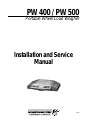
1
PW 400 / PW 500
Portable Wheel Load Weigher
Installation and Service
Manual
37881
Contents
1.0
Introduction .............................................................................................................................. 1
1.1
1.2
1.3
1.4
2.0
Operation .................................................................................................................................. 3
2.1
2.2
2.3
2.4
2.5
2.6
2.7
2.8
2.9
3.0
General Description .................................................................................................... 1
Functional Description ................................................................................................ 1
Physical Description ................................................................................................... 2
Options and Accessories ............................................................................................ 2
Portable Weighing Procedures ................................................................................... 3
Transient Weight Shifting ........................................................................................... 3
Selection of Weigh Sites ............................................................................................. 3
Wheel Placement ....................................................................................................... 4
Controls and Indicators ............................................................................................... 4
Reading the Weigher Display ..................................................................................... 5
Operating Instructions ................................................................................................ 6
Local/Total Operation ................................................................................................. 6
Weigher Bus Address ................................................................................................. 7
Maintenance ............................................................................................................................. 8
3.1
3.2
3.3
3.4
3.5
3.6
3.7
3.8
3.9
3.10
3.11
3.12
3.13
3.14
Recharging the Battery ............................................................................................... 8
Removing the Platform ............................................................................................... 9
Removing Links .......................................................................................................... 9
Removing the Display Cover ...................................................................................... 9
Removing the PC Board ........................................................................................... 10
Removing the Battery ............................................................................................... 11
Inspection and Cleaning ........................................................................................... 11
Inspection Prior to Assembly .................................................................................... 11
Lubrication ................................................................................................................ 12
Reassembly .............................................................................................................. 12
Installing the PC Board ............................................................................................. 12
Reassembling the Display Cover ............................................................................. 12
Reassembling Links ................................................................................................. 12
Reassembling the Platform ...................................................................................... 13
4.0
Calibration Verification .......................................................................................................... 13
5.0
Calibration Instructions .......................................................................................................... 14
6.0
Replacement Parts ................................................................................................................. 16
7.0
Wiring Diagram ...................................................................................................................... 18
PW 400 / PW 500 Limited Warranty ................................................................................................... 19
Copyright ©1997 Rice Lake Weighing Systems. All rights reserved. Printed in the United States of America.
Specifications subject to change without notice.
January 1997
1.0
Introduction
This manual contains operating and service procedures for both the PW 400 and PW 500 Portable Wheel
Weighers.
1.1
General Description
The PW 400 and PW 500 Portable Wheel Weighers are microprocessor controlled, hydraulically operated,
static weighers designed to measure weight applied anywhere within the weighing surface. The weighers are
packaged in a rugged, corrosion resistant, lightweight enclosure specifically designed to meet the demand of
daily outdoor operation.
The PW 400 and PW 500 are identical in operation. The main difference in the two models is the size of the
platform. The PW 400 platform is 10" x 11" to handle most standard truck tires, while the larger PW 500
platform at 13.5" x 11" is suitable for trucks with oversize tires or dual wheels. Both the PW 400 and PW 500
in 20,000 lb capacity x 50 lb display division models are NTEP certified Class IIII for commercial use.
Each weigher is powered by either a rechargeable or non-rechargeable battery. A variety of optional charging
units are available for the rechargeable models, allowing them to be charged from 110 VAC, 220 VAC, or 12
VDC power sources.
The units have 20-degree integral ramps that allow for easy drive-on/off and a nonskid bottom for operator
safety. Optional larger approach ramps are available to give a more gradual approach slope and longer
footprint.
Weighers can be used in one of two modes:
1. In Local mode, each weigher displays only its own load.
2. In Total mode, multiple weighers can be interconnected in series to allow as many as 30 units to be
used together. Each weigher displays the total weight of all interconnected weighers.
Initial calibration of each weigher is performed at the factory and no field adjustments are necessary.
Recalibration is necessary only after repair or replacement procedures.
1.2
Functional Description
The weight applied to the platform of the weigher undergoes a series of transformations before being displayed to the operator. The first transformation is the weight becoming a directed force transferred by a series
of mechanical links to a single hydraulic load cell fitted with an electronic pressure transducer.
The load cell contains a non-compressible fluid that exhibits a known viscosity over the operating pressure
and temperature range. Any change in pressure is detected by the pressure transducer which supplies an
electrical signal that is proportional to the weight applied to the weigher platform.
The electrical signal is converted to a digital format that is transmitted to the microprocessor. The microprocessor decodes the digital signal and transmits the weight information to the display.
1
1.3
Physical Description
Overall length
20 1/2 inches
Width, main body
14 inches
Width, including handle
17 3/4 inches
Width, weighing surface
10 1/2 inches (PW 400); 13 1/2 inches (PW 500)
Length, weighing surface
11 inches
Height, nominal
3 inches
Height, maximum
3-1/8 inches
Ramp slope angle
20 degrees
Weight, complete unit
46 pounds (PW 400); 50 pounds (PW 500)
Weighing capacity
20,000 pounds / 10,000 kilograms
Accuracy
As per NIST Handbook 44
±50 Lbs. (0–2,500 lbs.)
±100 Lbs. (2,501–10,000 lbs.)
±150 Lbs. (10,001–20,000 lbs.)
Approvals
20,000 lb x 50 lb models are NTEP-certified
Class IIII, CC #96-166, nmax = 400
Operating Temperature Range
0–120°F
Storage Temperature
-35–150°F
Humidity (Operating and Storage) 100%, non-condensing
Power Requirements
1.4
12 VDC
Options and Accessories
The following table shows the options and accessories available for the PW 400 and PW 500 Portable Wheel
Load Weighers. Battery chargers listed in the table show the required power source and the number of wheel
weighers that can be charged using the listed charger.
Option/Accessory
RLWS
Part Number
Approach ramps, PW400
37290
Approach ramps, PW500
37291
Communication cable
(required for local/total interconnect)
37289
Battery Charger, 120 VAC, 1-scale
37285
Battery Charger, 12 VDC, 2-scale
37286
Battery Charger, 12 VDC, 4-scale
37287
Battery Charger, 12 VDC, 6-scale
37288
2
2.0
2.1
Operation
Portable Weighing Procedures
The PW 400/PW 500 Portable Wheel Load Weigher is specifically designed to indicate the weight of an
individual wheel resting at any position within the weighing area. The operator must follow the basic principles of portable weighing in order to obtain accurate and reliable results. Improper weighing procedures can
induce errors into the weighing process that are no fault of the weigher.
Accurate vehicle axle or gross weight cannot be arrived at by measuring a single wheel, a single side, or a
single axle within an axle group. An axle group is defined as any group of axles that share a common linkage
between them, whether it be mechanical, hydraulic or pneumatic. Both sides of any axle must be weighed at
the same setting. In the case of a tandem axle group, all four wheels must be weighed at the same setting.
The PW 400 and PW 500 weighers are precision weight indicators. By using correct techniques, excellent and
dependable results will be achieved.
2.2
Transient Weight Shifting
The largest single factor determining the accuracy of portable weighing is transient weight shift within the
vehicle itself.
Transient weight shifting can best be defined as weight which is transferred from one axle to another due to:
•
Placing one axle in an unusual attitude in relation to another by lifting off a normal plane.
•
Placing the vehicle in a non-level position due to poor approach or poor choice of weigh site.
•
Physical contact of tire with ground.
Axles are naturally lifted off a normal plane any time that the weigher platform is above ground level. The
amount of transient weight shift is a direct function of the distance that the axle is lifted. Using the correct
number of weighers reduces transient weight shift to a minimum. Hence, reducing the number of consecutive
weighments required will result in a more accurate weighing. Axles spaced within 12 feet or closer should
always be weighed at the same setting.
The balance of the transient weight shift may also be compensated for by placing simple blocks, approximately 3 inches in height, under the conflicting axle so as to create a level plane.
Example: When single or tandem drive axles are weighed, the steering axle should be elevated to the same
level as the weigher platform. When the steering axle is weighed, drive axles should be elevated to platform
level. This also applies to coupled trailers with short axle spacing.
The transient shift between drive axles and most trailer axles is normally insignificant and no blocks need be
used.
2.3
Selection of Weigh Sites
Selection of a suitable weigh site is a prerequisite to accurate weighing. Ideal weighing sites should be flat,
level and hard surfaces. Approaches should be long enough for a straight-line movement of the vehicle prior
to and during the weighing. Realizing the problems of finding ideal weighing surfaces, the PW 400/PW 500
weigher is designed to weigh on a side slope, not exceeding 3 degrees, and on any relatively flat surface
capable of holding the weigher above ground. The site chosen should not be up- or downhill, in a hollow or
on a crest, as these conditions will redistribute the weights of the axles.
3
2.4
Wheel Placement
Correct wheel placement is necessary for accurate weighing of vehicles. For best results, the ramp approach
of each weigher should be firmly seated against the tires and the weigher platform centered with the wheel
prior to driving the vehicle onto the weigher.
Occasionally the outside tire has such low air pressure that the inside tire of a dual set does not clear the
ground. This will give an erroneous reading since the inner tire is bearing part of the load. The PW 400/PW
500 weigher design is such that either tire may be used. To weigh inside tires, turn the weigher 180 degrees
and continue weighing. The sum of the wheel weights will still equal the axle weight.
Experience is the real key to successful portable weighing. Incorrect weighing results can usually be attributed to improper procedure. Following these basic rules of portable weighing will insure the best possible
results.
2.5
Controls and Indicators
Figure 1 shows the weigher display and controls conveniently located on the handle side of the weigher. The
display is a 1 line, 16 character, alphanumeric liquid crystal display (LCD) with a magnified character height
of 1/2 inch. The display is backlit for night time operation of the weigher.
Operational switches and connectors are shown in Figure 1 and function as follows:
RST-OFF/ON
ZERO
LCL/TTL
Display
COMM
CHGR
Figure 1— Controls and Indicators
RST-OFF/ON
This is a sealed, double-pole, double-throw momentary toggle switch.
Press the switch to the right and release to turn the weigher ON.
Press the switch to the right again and release to turn the weigher OFF.
ZERO
This is a sealed, momentary push-button switch.
Press the switch to ZERO the display before weighing.
LCL/TTL
This is a sealed, momentary push-button switch. Press the switch to toggle between the LOCAL and
TOTAL modes. (Requires two or more weighers be connected together via communication cable).
4
ZERO and LCL/TTL
Activates or deactivates the display backlighting. Press both buttons at the same time to turn the display
backlighting ON or OFF.
COMM
Communication connector for connecting two or more weighers together for Local/Total function or
remote communications.
CHGR
Connection for input to recharge weigher battery.
Maximum charge is 13.5 VDC at 300 mA
2.6
Reading the Weigher Display
The PW 500 weigher is capable of indicating informational messages to the operator as well as the weight
value. These messages and their meaning are given below:
OUTPUT MESSAGE
“
MEANING
”
Displayed at power up.
BUS ADDRESS = # #”
Number assigned to weigher communication functions.
“CALIBRATE ZERO”
Unit performing zero function.
“# # # # # LB”
Local weight in pounds.
“# # # # # KG”
Local weight in kilograms.
“MOTION ERROR”
Failure of unit to achieve a stable zero setting.
“RANGE ERROR”
Weigher output exceeds zero range capability.
“OVER-RANGE”
Weigher output exceeds capacity of weigher.
“LOW BATTERY”
Intermittent message meaning battery is becoming low.
Recharge at first opportunity.
“RECHARGE BATTERY”
Battery too low to provide accurate weight indication.
Recharge before use.
“## TOTAL SCALES”
This message is followed by the number of weighers within
an interconnected group.
“BAD COMM ADDRESS”
The address number assigned to each weigher is duplicated
within the group.
“NO SCALES ANSWER”
None of the weighers connected can communicate with any
other weigher.
“NO COMM RESPONSE”
Communications interrupted between two or more weighers.
“FORCED TO LOCAL”
Weigher has returned to LOCAL weighing mode due to
interruption or lack of communication response.
“NEW ADDRESS = # #”
Acceptance of new address number assigned to weigher.
“RELEASE ZERO”
Message to operator to remove hand from ZERO button.
5
2.7
REMOTE OUTPUT MESSAGE
“TOT # # # # # LB”
MEANING
Total weight in pounds.
“TOT # # # # # KG”
Total weight in kilograms.
“REM LOW BATTERY”
Battery of interconnected weigher is becoming low.
Recharge at first opportunity.
“REM RECHARGE”
Battery of interconnected weigher is too low to provide
accurate weight indication. Recharge before use.
“REM ZERO ERR”
Failure of interconnected weigher to zero.
“REM OVER-RANGE”
Output of interconnected weigher exceeds its capacity.
Operating Instructions
With the battery charged and the weigher ready to use, do the following:
1. Place the weigher in the weighing position.
2. Turn the weigher on by pressing the RST-OFF/ON switch to the right. The weigher display lights up
halfway and then completely across the viewing area testing each segment of the LCD. This is
followed by the “BUS ADDRESS” value that has been assigned to the weigher (See Section 2.9,
Weigher Bus Address). The bus address number is followed by the message “CALIBRATE ZERO”.
At this point the weigher self-zeros and is ready for use.
3. The weigher can be manually zeroed at any time prior to application of load. Push the ZERO button
to obtain a zero reading if any number other than zero is displayed. Figure 1 on page 4 shows the
location of the zero control.
4. Slowly move the vehicle to be weighed onto the weigher and ensure that the tire is approximately
centered on the weigher platform.
5. Read the weight on the display.
6. If a weigher fails to indicate a weight, move the vehicle off the weigher and push the “RST-OFF/ON”
switch to the left to reset the weigher. Repeat steps 4 and 5.
2.8
Local/Total Operation
Located on the front of the weigher is the communications connector labeled COMM. This connector is used
for scale interconnections for the total mode of operation. This mode of operation allows up to 30 interconnected weighers to display the total weight applied to those weighers.
When connecting and operating the weighers in the total mode, the operator must turn each weigher on
separately. Once communications is established, all connected weighers automatically operate as one. For
example, if the TOTAL button is activated on one weigher, all connected weighers will change to the total
mode of operation. Similarly, if the OFF switch is pressed on any of the connected weighers, all weighers will
turn off and return to the local default mode.
6
Following is the procedure for connecting four weighers together for total operation:
1. Turn off the weighers to be interconnected.
2. Attach a communication cable from weigher #1 to weigher #2.
3. Attach a communication cable from the breakout receptacle of the first cable to the #3 weigher.
4. Attach a communication cable from the breakout receptacle of the second cable to the #4 weigher.
5. Turn the weighers on.
6. Press the LCL/TTL button on any weigher.
7. The display will show “WAITING FOR COMM” .
8. After communications with all weighers attached is achieved, the display will show “04 TOTAL #4”.
This means that all 4 weighers are in communication with each other.
9. The display will show “TOT XXXXX LB” on all scales interconnected.
10. Press the ZERO pushbutton on any weigher. If all weighers zero, they are ready for use.
If any connected weigher remains in local mode, communication with that unit is not established. Check the
cable for bad connections or broken pins. When communication is established, the weighers display the total
number of weighers communicating.
2.9
Weigher Bus Address
When operating in the TOTAL mode, each weigher must have its own bus address. If two or more weighers
have the same bus address, communication cannot be properly established. Referring to the example given in
Section 2.8, Local/Total Operation, the four weighers connected must have four different bus addresses.
These addresses can be any number from 1 to 30.
No two weighers can have the same number. To change the bus address, perform the following steps:
1. Turn the weigher off.
2. While holding the ZERO pushbutton down, turn the weigher on.
3. The display will read “RELEASE ZERO”. Release the ZERO pushbutton.
4. The display will read “NEW ADDRESS XX”, where XX is a number from 01 to 30. Press the
LCL/TTL pushbutton to increment the number.
5. After a new number has been selected, press the ZERO pushbutton. The weigher will operate as it
would under normal local operation.
7
3.0
Maintenance
The PW 400/PW 500 weigher is designed to give many years of trouble-free service. However, in cases
where a large number of portable weighers are in constant use and facilities are available, it may be desired to
perform in-house maintenance rather than returning units to the factory. By carefully following instructions,
normal maintenance and repairs can be easily accomplished.
3.1
Recharging the Battery
! Caution
Do not connect battery charger if weigher is powered by non-rechargeable
batteries!
Regular charging of the weigher’s internal battery is necessary to ensure successful day to day operation and
long battery life.
The length of time allowed to recharge the battery is just as important as how often the battery is recharged.
When fully charged, the battery operates the weigher for approximately 8 to 10 hours. This varies depending
on the temperature of the environment in which the weigher is used and stored, charging patterns and the age
of the battery. The weigher displays the following error messages to alert the operator about the battery
condition:
LOW BATTERY
This message appears approximately once every 8 seconds to alert the operator that the battery is becoming low. Accurate weight readings will still be displayed in between “LOW BATTERY” indications. The
battery should be charged at the first opportunity.
RECHARGE BATTERY
This message is displayed continuously to alert the operator that the battery voltage is too low to allow
accurate weight indication to be displayed. The weigher battery must be charged at this time.
When in total mode, warning messages will be displayed for all remote scales. These messages are “REM
LOW BATTERY” and “REM RECHARGE”, indicating that a remote scale’s battery is low or needs to be
recharged. Switch to Local mode to tell which weigher has the low battery.
The weigher battery should be charged a minimum of 12 hours if it has been discharged to the point that the
“LOW BATTERY” message is displayed. Charging periods of less than 4 hours are usually ineffective
regardless of the depth of discharge.
Battery charge dissipates rapidly during extreme heat conditions even when the weigher is not in use. If the
weigher is to be stored and charged from a transport vehicle, frequent charging may be required. At least four
hours are needed for the battery to sustain any real degree of charge. Charging the battery only when the
transport vehicle is being operated provides little real degree of charge and can shorten battery life. An
overnight charge is preferred as temperatures are usually cooler at night.
NOTE: Prolonged recharging from a transport battery (in excess of 24 hours) may discharge
the transport vehicle battery.
The charger is equipped with one red and six green LED indicators mounted on the top side of the charging
unit. The red LED indicates that power to the charging unit is on. The green LEDs indicate that the weigher
battery is accepting a charge. When connecting the weighers to the charging unit, look to see that the corresponding green light is on to verify that the weigher battery is drawing current from the charger. The green
light will go out when the weigher battery is drawing 50 mA or less current from the charger, indicating that
the battery is fully charged.
An optional 110/120 VAC charging station is also available for use in calibration labs and maintenance areas.
8
3.2
Removing the Platform
Snap rings (see #8 in Figure 2 below) are sealed at the factory with silicone sealer to ensure proper environmental protection of electronics. Before disassembly, remove seals with a pick or another sharp instrument.
1. Place weigher on a flat surface, bottom down.
2. Insert a 5/32” Allen wrench into the head of set screws (51) and, by rotating in counterclockwise
direction, loosen both set screws one full turn.
3. Turn weigher over, top down, and with True Arc pliers remove snap rings (8) and disc-spring seals
(4).
4. Insert a 1/4” Allen wrench in bolt retainer (6). Turn counterclockwise to remove both bolts (6),
washers (5), and springs (7). The platform is now free of the base.
5. Being careful to hold the platform to the base, turn the weigher over, bottom down. Carefully lift the
platform straight up and separate the platform from the base. Place platform, top down, beside
weigher body.
51
4
5
6
7
8
69
70
50
Figure 2 — Weigher Top & Bottom
3.3
Removing Links
Links must be returned to their original position when reassembling the weigher. Take care that their working
positions are maintained. To remove links:
1. Remove the platform as described in Section 3.2.
2. Remove links by lifting straight up and off of the link retaining pins.
3.4
Removing the Display Cover
Bolt heads are sealed at the factory with silicone sealer to ensure proper environmental protection of electronics. Remove seals with a pick or another sharp instrument.
1. Remove the platform as described in Section 3.2.
2. Use a 3/32” Allen wrench to remove the two screws (50). Remove the display cover by lifting straight
up. Tilt the display cover forward such that the display cable is accessible and unplug the cable from
the PC board.
9
3.5
Removing the PC Board
Use the following procedure to remove the PC board:
1. Remove the platform (see Section 3.2) and display cover (see Section 3.4).
Wear a grounded wrist strap to prevent electrostatic discharge damage to PC board.
2. Unplug connectors J1, J2, J3, J5, J6 and J7. Take care to prevent damage to the connectors and wiring
harness.
3. Remove four screws at PC board corners.
4. Lift out PC board.
P2
U7
U4
J1
U10
1
2
3
4
U11
J2
1
2
3
4
5
6
JMP1
U6
U8
SW1
5005-00052A
MADE IN USA
U3
JMP2
U2
J5
Figure 3 — PC Board
10
1 2 3 4
J5
J6
2
1
J7
2
1
J3
2
1
3.6
Removing the Battery
Use the following procedure to remove the battery from the weigher. See Figure 4 for component locations.
1. Remove the 6 screws (70) around the outer edge of the battery compartment cover (69).
2. Lift out battery (66) and unplug connector.
70
69
66
Figure 4 — Battery Removal
3.7
Inspection and Cleaning
All weigher parts should be carefully cleaned and inspected prior to assembly to assure proper working
conditions.
All parts, with the exception of all electronic components, should be cleaned with kerosene only. Do not use
carbon tetrachloride, acetone, or any other organic cleaning agent. The use of organic-based agents is extremely detrimental to the nonmetallic elements within the unit and will cause premature failure. Electronic
components should be removed from the weigher and cleaned in alcohol and thoroughly dried before reassembly. While cleaning electronic components, do not disturb the factory settings of the potentiometers.
Under no circumstances should the weigher be cleaned with steam or pressure type cleaners. Avoid using
caustic or acid base solutions as these can damage seals and other components.
3.8
Inspection Prior to Assembly
Use the following procedure to prior to reassembling the weigher platform. See Figure 5 on page 16 for
location of numbered parts.
1. Inspect piston pivot (13) for excessive wear and proper fitting.
2. Inspect platform buttons (43) for excessive wear.
3. Inspect platform load strips (18) and (19) for signs of unusual wear at contact points and proper fitting
of resilient retainer (17). Depth of wear must not exceed 0.002 inch.
11
4. Inspect side load strips (24) for tightness in base and signs of wear. Side strips should be replaced
when depth of wear exceeds 0.003 inch.
5. Inspect link retaining pins (47) for tightness in base and signs of wear.
6. At bottom of base assembly, check load strips (19) for tightness in base and signs of wear. Load strips
should be replaced when depth of wear exceeds 0.003 inch.
7. Using a torque wrench, tighten diaphragm retaining screws (46) to 50 inch-pounds.
8. Inspect behind diaphragm bead (27) for loose particles.
9. Inspect the nine link pivots (13) for flat spots.
10. Inspect piston load strips (18) and (19) for signs of unusual wear and resilient retainer (17) for fit.
11. Inspect piston (14) for nicks or burrs.
12. Inspect all load strip rollers (20) for straightness and flat spots.
13. Inspect all electrical connections for corrosion.
3.9
Lubrication
Prior to assembly, all unplated steel parts should be coated with grease or some rust-inhibiting agent. Side
buttons and load strip assemblies must be packed with Shell Darina AX or an equivalent extreme-pressure
grease.
3.10 Reassembly
After all parts have been cleaned and inspected, the weigher can be reassembled.
3.11 Installing the PC Board
Position the PC Board in the weigher and secure using the four screws (61). Connect the cables as shown with
the exception of the display connector.
3.12 Reassembling the Display Cover
The metal mating surfaces around the display cover and the base assembly must be sealed for environmental
protection. Reconnect the display cable. Place the display cover in position and install the holding screws
(50). After tightening the screws, place a small amount of silicone over the screw heads. Apply a thin film of
RTV silicone rubber compound around all mating surfaces.
3.13 Reassembling Links
Use the following procedure to reassemble the links. See Figure 5 on page 16 for location of numbered parts.
1. Replace the link bushings (15) into links (9) and (10) so that the small hole of bushing faces the
bottom of base assembly.
2. Pack grease into the piston load strip assembly (16) and the chamfered corners of the upper strip (18)
to the piston top.
3. Grease upper and lower link bearings (13).
4. Place links over retaining pins (47).
Note: Links must be returned to original position.
12
3.14 Reassembling the Platform
Use the following procedure to reassemble the weigher platform. See Figure 5 on page 16 for location of
numbered parts.
1. Grease and replace lower load strips (19), retainers (17), needle bearings (20), and upper load strips
(18), with chamfered corners on upper load strip facing links.
2. Grease platform buttons (43).
3. Carefully insert platform into base.
4. Holding platform and base together, turn the weigher upside down.
5. Insert spring housing (3) and springs (7).
6. With a 1/4” Allen wrench, install spring retaining bolts (6) and washers (5) by turning in a clockwise
direction until hard stop is felt. Then turn back counterclockwise 3/4 of a turn.
7. Use a screwdriver to pry ends of platform away from base. Platform should move a small amount and
before stopping. If platform cannot be separated, back off spring retaining bolts 1/4 turn.
8. Adjust spring bolts until 0.015 to .030 inches of movement occurs between platform ends and base
before hard stop is felt.
9. Install disk seals (4) and snap rings (8).
10. Turn weigher over, base down. Use a 3/32” Allen wrench to tighten set screws (51). Seal set screws
and disc seals with silicone and let silicone dry.
11. Platform assembly is now complete.
4.0
Calibration Verification
Each PW 400/PW 500 weigher is fully calibrated and tested at the factory before shipment. The weigher is
checked at five or more points to ensure accuracy of calibration over the weighing range of the scale. Special
equipment is used to simulate vehicle passage and assure that calibrations are stabilized and will not change
with normal usage. See Section 1.3 for calibration tolerances.
Verification of the accuracy of a static weigher consists of placing known certified weights, or calibrated
force, on the platform of the weigher and then comparing the weight reading on the display to the weight or
force on the platform. Weighers can be checked individually or in pairs. A Force Load Calibration Press is
recommended for operator safety and ease of operation. Procedures for checking calibration on a force load
machine are as follows:
1. Position weigher on the press/surface.
2. Place a 10 inch by 10 inch steel plate that is at least 1 inch thick on the platform. The plate distributes
the force load evenly across the weigher platform load buttons and prevents point loading the center
of the platform.
3. Turn the weigher ON and allow to warm-up for 5 minutes.
4. Before checking the calibration, exercise the weigher by applying a force of weigher capacity to the
platform and then remove the force. Repeat this exercise for a total of 3 times.
5. Press the ZERO button to zero the weight displayed. (This tares off the weight of the plate.)
6. Check for calibration accuracy at the following five (5) points: 2,000 lbs or 1,000 kg; 5,000 lbs or
3,000 kg; 10,000 lbs or 5,000 kg; 15,000 lbs or 7,000 kg; 20,000 lbs or 10,000 kg.
13
Apply force slowly and symmetrically. A weight applied quickly can far exceed
the weigher limit. If using dead weight, align center line of weight to center
line of scale.
7. If the weigher indication falls outside the tolerances given in Section 1.3 at any points, recalibrate the
weigher following the calibration instructions given in Section 5.0 below.
! Caution
5.0
Calibration Instructions
After performing the test outlined in Section 4.0, Calibration Verification, calibration of the PW 400/PW 500
is needed if the weigher indication exceeds the tolerances described in Section 1.3.
Factory calibration is performed using a calibrated hydraulic press to apply the required force loads. Dead
weights can be used to apply the required loads, however, it is recommended for safety reasons to use a
hydraulic press for calibration. Accuracy of the press must be .25 %or better (prefer .1% accuracy). If the
appropriate equipment is not available, return the unit to Rice Lake Weighing Systems for calibration.
1. Remove the Platform and Display cover as described in Sections 3.2 and 3.4.
2. Referring to Figure 3 on page 10, locate the switch SW1 on the PC Board. Set switch #4 to ON.
3. Reassemble the Platform to the base as instructed in Section 3.14.
4. Position the weigher on the press/surface to be used for calibration.
5. Connect the display cable to the J5 receptacle located on the PC Board. Position the display cover
assembly so that the display will not short circuit to the base and will not interfere with the platform.
6. Place the RST-OFF/ON to the ON position. The display will read “BUS ADDRESS=XX”, “CAL
ROUTINE”, and “ZERO FOR CAL PTS”. Now quickly press the ZERO push button. The “ZERO
FOR CAL PTS” is a timed function, and if the ZERO button is not pressed in time the display will
show “SET SW 4 TO OFF”. If this happens, turn the weigher OFF then back ON and try again.
7. Place the 10 inch by 10 inch steel plate used for calibration verification on the weigher platform.
8. The display will show “EXERCISE TO 20K” and “THEN PRESS ZERO”. Apply a force to the
weigher platform equivalent to 20,000 lbs. Remove the force, then press the “ZERO” button. Repeat
this operation three times.
9. After exercising the weigher three times and pressing the“ZERO” button, the display will read “PT 1
READY” momentarily, then show “XXXX CNTS”. Apply a force of 1,000 lbs. to the weigher.
Allow the force indicator to stabilize and press the ZERO push button.
10. The display will show “PT 2 READY” momentarily, then show “XXXX CNTS”. Increase the force
to 5,000 lbs. Allow the force indicator to stabilize and press the ZERO push button.
11. The display will show “PT 3 READY” momentarily, then show “XXXX CNTS”. Increase the force
to 10,000 lbs. Allow the force indicator to stabilize and press the ZERO push button.
12. The display will show “PT 4 READY” momentarily, then show “XXXX CNTS”. Increase the force
to 15,000 lbs. Allow the force indicator to stabilize and press the ZERO push button.
13. The display will show “PT 5 READY”. Increase the force to 20,000 lbs. Allow the force indicator to
stabilize and press the ZERO push button.
14. After the #5 calibration point is entered, the display will show “SET SW 4 OFF”. Remove the force
on the weigher platform. Place the #4 switch on SW1 of the electronics PC Board to OFF position.
14
15. This completes the calibration of the weigher. Verify calibration as instructed in Section 4.0, Calibration Verification. If weigher is still outside the tolerances specified in Section 1.3, turn the unit OFF
and perform the steps required in Section 3.0, Maintenance. After completing Section 3.0, repeat
steps 1 through 15 again. If the weigher is still outside the tolerances, return the weigher to Rice Lake
Weighing Systems for adjustment.
16. After verification of calibration is complete, turn the weigher OFF. Disconnect the display cable and
remove the weigher platform.
At this point, the operational performance characteristics of the weigher can be set using SW1 on the
PC board. The SW1 switch functions are listed below:
SWITCH NO.
POSITION
RESULT
#1
#2
#1 and #2
#3
ON
ON
OFF
ON
OFF
OFF
Operation in 20 LB/10 KG Increments
Operation in 10 LB/5 KG Increments
Normal 50 LB/20 KG Increments
Display in KG Operation
Display in LB Operation
Normal Operation
ON
Calibration Mode
#4
17. Reassemble the weigher as described in Section 3.10 – 3.14.
15
6.0
Replacement Parts
This section contains an exploded view of the PW 400/PW 500 weigher followed by an associated replacement parts list. Callout numbers on the exploded view correspond to item numbers on the parts list. Some
callouts are shown elsewhere in this manual for user convenience.
When ordering replacement parts, be sure to include the full part number and quantity required.
14 16
9
10
15 11 13
15 13 12
52
24
19
26
2 21 22 23 45
47
39 40 41 42
89 88 65
63
34
16
3
7
46 25
5
6
79
4
8
76 78 82 83 84
66
69
72 77 78 82 83 84
68
60
85
61 62 88 89
27
55
74
56
88
59
89
57
71 31
80
75 49
81
30
54
50
50 73
82
53
64
83
28
58
29
Figure 5 — Weigher Exploded View
No.
1
2
3
4
5
6
7
8
9
10
11
12
Description
ASSEMBLY, Wheel Weigher
NAMEPLATE
SPRING HOUSING, Platform Retainer
Spring Housing Seal
WASHER, Platform Retainer
BOLT, Platform Retainer
(5/16-18x2", Soc. Hd. Cap Screw)
SPRING, Platform Retainer
SNAP RING, Disc Retainer (Waldes Tru Arc, Cad. Plate)
ASSEMBLY, Piston Link
ASSEMBLY, Pivot Link
LINK, Machined Aluminum (Piston Side)
LINK, Machined Aluminum (Pivot Side)
16
Quantity
1
1
2
2
2
2
2
2
1
1
1
1
43
44
13
14
15
16
17
18
19
20
21
22
23
24
25
26
27
28
29
30
31
34
40
41
42
43
44
45
46
47
48
49
50
51
52
53
54
55
56
57
58
59
60
61
62
63
64
65
BEARING, Link (1-3/4")
PISTON
BUSHING, Link
ASSEMBLY, Load Strip (2")
RETAINER, Load Strip Resilient (2")
LOAD STRIP, Upper (2")
LOAD STRIP, Lower (2")
NEEDLE BEARING, Load Strip
ASSEMBLY, Base
SUBASSEMBLY, Base
BASE, Machined
LOAD STRIP, Base Side (1")
RING, Diaphragm Retainer
GASKET, Base
DIAPHRAGM
ASSEMBLY, Dial Cover
DIAL COVER, Machined
LENS, Magnifying
SWITCH PLATE ASSEMBLY
ASSEMBLY, Plumbing
ASSEMBLY, Platform (2" load strips)
SUBASSEMBLY, Platform (2" load strips)
PLATFORM, Machined (2" load strips)
DRIVE SCREW BUTTON, Platform
WASHER, Drive Screw Button Handle
DRIVE SCREW, Nameplate Retaining
SCREW, Diaphragm Retaining 10-24 x 5/8 Sol. hd cap
PIN, Link Retaining
SCREW, Flex Handle Retaining 1/4 - 20 x 1/2 pan hd slot
SEAL, Panel Switch
SCREW, Display Cover Retaining,Switch Panel,
(#4-40 x 1/2 Soc. Hd. Cap Scr., Cad. Plate)
SET SCREW, Platform Retaining
(5/16-18 x 3/8 Hex Soc. Hd. Cap Scr.,Cad. Plate)
SCREW, Piston Retainer
(5/16-18 x 7/8 Soc. Hd. Cap Scr., Cad. Plate)
HANDLE ASSEMBLY, Flexible
HANDLE
FLEX SPRING, Handle
INSERT, Spring Support
INSERT, Handle Support
END CAP, Handle
SCREW, Handle Support
(#10 - 24 x 3/4", Pan Hd., Cad. Plate)
PC BOARD ASSEMBLY
SCREW, PC Board Retaining;
Transducer Clamp; (#6-32 x 3/8 Phil Pan HD, SS)
NYLON SPACER for PC board (1/8 x 0.25 OD x 0.14 ID)
TRANSDUCER
BOOT, Switch
CLAMP, Transducer Retaining
17
9
1
4
5
5
5
9
40*
1
1
1
8
1
1
1
1
1
1
1
1
1
1
1
16*
16*
4
12
4
2
2
6
2
3
1
1
2
2
2
2
2
1
7
4
1
1
1
66
BATTERY, 12 VDC Rechargeable
68
GASKET, Battery cover
69
COVER, Battery
70
SCREW, Cover (#6-32 x 1/4 Flat Hd., 82° SS)
71
SWITCH, RST-OFF/ON
72
Communications Connector Assy.
73
SWITCH, Momentary Pushbutton, Zero and LCL/TTL
74
Cable Clamp
75
TAG, RST-ON/OFF, Zero, LCL/TTL
76
CHARGER CONNECTOR ASSY.
77
TAG, Comm. Chgr.
78
GASKET, CONNECTOR
79
CONNECTOR ASSY, Battery wires
80
DISPLAY ASSY.
81
NYLON, # 4 Shoulder Spacer
82
#4 - 40 x 1/2 Phillip Pan Hd. Scr. S.S.
83
#4 Split Lock Washer
84
Cap, Connector Dust Seal
85
BRACKET ASSY., AA 1.5V Battery
87
#6 Hex Nut S.S.
88
#6 Split Lock Washer
89
#6 Flat Washer
*Quantity may vary due to engineering changes.
7.0
1
1
1
10
1
1
2
2
1
1
1
2
2
1
4
12
12
2
2
4
11
11
Wiring Diagram
P2
U4
J1
RED
GRN
WHT
BLK
U7
U10
1
2
3
4
U11
J2
SWITCH
ASSY
RED
ORG
GRN
WHT
BLU
BLK
1
2
3
4
5
6
U6
JMP1
U8
SW1
5005-00052A
MADE IN USA
U3
J6
2
J7
1
J3
JMP2
U2
J5
1 2 3 4
J5
WHT
RED COMM.
RED
DISPLAY ASSY
18
BLK
RED
2
1
2
1
BLK
RED
CHARGER
BATTERY
PW 400 / PW 500 Limited Warranty
Rice Lake Weighing Systems (RLWS) warrants that all RLWS equipment and systems properly installed by a
Distributor or Original Equipment Manufacturer (OEM) will operate per written specifications as confirmed
by the Distributor/OEM and accepted by RLWS. All systems and components are warranted against defects
in materials and workmanship for one (1) year.
RLWS warrants that the equipment sold hereunder will conform to the current written specifications authorized by RLWS. RLWS warrants the equipment against faulty workmanship and defective materials. If any
equipment fails to conform to these warranties, RLWS will, at its option, repair or replace such goods returned within the warranty period subject to the following conditions:
•
Upon discovery by Buyer of such non-conformity, RLWS will be given prompt written notice with a
detailed explanation of the alleged deficiencies.
•
Individual electronic components returned to RLWS for warranty purposes must be packaged to prevent
electrostatic discharge (ESD) damage in shipment. Packaging requirements are listed in a publication,
“Protecting Your Components From Static Damage in Shipment,” available from RLWS Equipment
Return Department.
•
Examination of such equipment by RLWS confirms that the non-conformity actually exists, and was not
caused by accident, misuse, neglect, alteration, improper installation, improper repair or improper testing;
RLWS shall be the sole judge of all alleged non-conformities.
•
Such equipment has not been modified, altered, or changed by any person other than RLWS or its duly
authorized repair agents.
•
RLWS will have a reasonable time to repair or replace the defective equipment. Buyer is responsible for
shipping charges both ways.
•
In no event will RLWS be responsible for travel time or on-location repairs, including assembly or
disassembly of equipment, nor will RLWS be liable for the cost of any repairs made by others.
THESE WARRANTIES EXCLUDE ALL OTHER WARRANTIES, EXPRESSED OR IMPLIED,
INCLUDING WITHOUT LIMITATION WARRANTIES OF MERCHANTABILITY OR FITNESS
FOR A PARTICULAR PURPOSE. NEITHER RLWS NOR DISTRIBUTOR WILL, IN ANY EVENT,
BE LIABLE FOR INCIDENTAL OR CONSEQUENTIAL DAMAGES.
RLWS AND BUYER AGREE THAT RLWS’S SOLE AND EXCLUSIVE LIABILITY HEREUNDER
IS LIMITED TO REPAIR OR REPLACEMENT OF SUCH GOODS. IN ACCEPTING THIS WARRANTY, THE BUYER WAIVES ANY AND ALL OTHER CLAIMS TO WARRANTY.
SHOULD THE SELLER BE OTHER THAN RLWS, THE BUYER AGREES TO LOOK ONLY TO
THE SELLER FOR WARRANTY CLAIMS.
No terms, conditions, understanding, or agreements purporting to modify the terms of this warranty shall have any legal effect unless
made in writing and signed by a corporate officer of RLWS and the Buyer.
© 1997 Rice Lake Weighing Systems, Inc. Rice Lake, WI USA. All Rights Reserved.
RICE LAKE WEIGHING SYSTEMS
Tel: 715-234-9171
• 230 WEST COLEMAN STREET • RICE LAKE, WISCONSIN 54868 • USA
Service Hotline: 715-234-2003
19
Fax: 715-234-6967