1
VS-700_r_e.book 1 ページ 2008年11月20日 木曜日 午後2時28分
6
-
0
1
*
VS-700_r_e.book 2 ページ 2008年11月20日 木曜日 午後2時28分
WARNING: To reduce the risk of fire or electric shock, do not expose this apparatus to rain or moisture.
CAUTION
RISK OF ELECTRIC SHOCK
DO NOT OPEN
ATTENTION: RISQUE DE CHOC ELECTRIQUE NE PAS OUVRIR
CAUTION: TO REDUCE THE RISK OF ELECTRIC SHOCK,
DO NOT REMOVE COVER (OR BACK).
NO USER-SERVICEABLE PARTS INSIDE.
REFER SERVICING TO QUALIFIED SERVICE PERSONNEL.
The lightning flash with arrowhead symbol, within an
equilateral triangle, is intended to alert the user to the
presence of uninsulated “dangerous voltage” within the
product’s enclosure that may be of sufficient magnitude to
constitute a risk of electric shock to persons.
The exclamation point within an equilateral triangle is
intended to alert the user to the presence of important
operating and maintenance (servicing) instructions in the
literature accompanying the product.
INSTRUCTIONS PERTAINING TO A RISK OF FIRE, ELECTRIC SHOCK, OR INJURY TO PERSONS.
IMPORTANT SAFETY INSTRUCTIONS
SAVE THESE INSTRUCTIONS
WARNING - When using electric products, basic precautions should always be followed, including the following:
1.
2.
3.
4.
5.
6.
7.
8.
9.
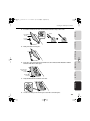
Read these instructions.
Keep these instructions.
Heed all warnings.
Follow all instructions.
Do not use this apparatus near water.
Clean only with a dry cloth.
Do not block any of the ventilation openings. Install in
accordance with the manufacturers instructions.
Do not install near any heat sources such as radiators,
heat registers, stoves, or other apparatus (including
amplifiers) that produce heat.
Do not defeat the safety purpose of the polarized or
grounding-type plug. A polarized plug has two blades with
one wider than the other. A grounding type plug has two
blades and a third grounding prong. The wide blade or the
third prong are provided for your safety. If the provided plug
does not fit into your outlet, consult an electrician for
replacement of the obsolete outlet.
10. Protect the power cord from being walked on or pinched
particularly at plugs, convenience receptacles, and the
point where they exit from the apparatus.
11. Only use attachments/accessories specified
by the manufacturer.
12. Unplug this apparatus during lightning storms or when
unused for long periods of time.
13. Refer all servicing to qualified service personnel. Servicing
is required when the apparatus has been damaged in any
way, such as power-supply cord or plug is damaged, liquid
has been spilled or objects have fallen into the apparatus,
the apparatus has been exposed to rain or moisture, does
not operate normally, or has been dropped.
For the U.K.
THIS APPARATUS MUST BE EARTHED
WARNING:
IMPORTANT: THE WIRES IN THIS MAINS LEAD ARE COLOURED IN ACCORDANCE WITH THE FOLLOWING CODE.
GREEN-AND-YELLOW: EARTH, BLUE: NEUTRAL, BROWN: LIVE
As the colours of the wires in the mains lead of this apparatus may not correspond with the coloured markings identifying
the terminals in your plug, proceed as follows:
The wire which is coloured GREEN-AND-YELLOW must be connected to the terminal in the plug which is marked by the
letter E or by the safety earth symbol or coloured GREEN or GREEN-AND-YELLOW.
The wire which is coloured BLUE must be connected to the terminal which is marked with the letter N or coloured BLACK.
The wire which is coloured BROWN must be connected to the terminal which is marked with the letter L or coloured RED.
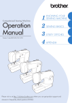
Before using this unit, carefully read the sections entitled: “IMPORTANT SAFETY INSTRUCTIONS” (p. 2), “USING THE UNIT SAFELY” (p. 3), and “IMPORTANT
NOTES” (p. 6). These sections provide important information concerning the proper operation of the unit. Additionally, in order to feel assured that you have
gained a good grasp of every feature provided by your new unit, VS-700 Owner’s Manual should be read in its entirety. The manual should be saved and kept
on hand as a convenient reference.
Copyright © 2009 ROLAND CORPORATION
All rights reserved. No part of this publication may be reproduced in any form without the written permission of ROLAND CORPORATION.
VS-700_r_e.book 3 ページ 2008年11月20日 木曜日 午後2時28分
USING THE UNIT SAFELY
Used for instructions intended to alert
the user to the risk of injury or material
damage should the unit be used
improperly.
to damage or
caused with
and all its
to domestic
Connect mains plug of this model to a mains socket
outlet with a protective earthing connection.
The ● symbol alerts the user to things that must be
carried out. The specific thing that must be done is
indicated by the design contained within the circle. In
the case of the symbol at left, it means that the powercord plug must be unplugged from the outlet.
008a
•
......................................................................................................................
003
•
Spec Page
......................................................................................................................
008e
•
Use only the attached power-supply cord. Also, the
supplied power cord must not be used with any other
device.
......................................................................................................................
......................................................................................................................
004
009
•
•
Do not excessively twist or bend the power cord, nor
place heavy objects on it. Doing so can damage the
cord, producing severed elements and short circuits.
Damaged cords are fire and shock hazards!
......................................................................................................................
010
•
......................................................................................................................
Fantom VS
Never install the unit in any of the following locations.
• Subject to temperature extremes (e.g., direct
sunlight in an enclosed vehicle, near a heating
duct, on top of heat-generating equipment); or are
• Damp (e.g., baths, washrooms, on wet floors); or are
• Exposed to steam or smoke; or are
• Subject to salt exposure; or are
• Humid; or are
• Exposed to rain; or are
• Dusty or sandy; or are
• Subject to high levels of vibration and shakiness.
This unit, either alone or in combination with an
amplifier and headphones or speakers, may be
capable of producing sound levels that could cause
permanent hearing loss. Do not operate for a long
period of time at a high volume level, or at a level that
is uncomfortable. If you experience any hearing loss or
ringing in the ears, you should immediately stop using
the unit, and consult an audiologist.
Make sure you always have the unit placed so it is level
and sure to remain stable. Never place it on stands
that could wobble, or on inclined surfaces.
......................................................................................................................
......................................................................................................................
011
•
Do not allow any objects (e.g., flammable material,
coins, pins); or liquids of any kind (water, soft drinks,
etc.) to penetrate the unit.
......................................................................................................................
3
Appendix
007
•
VS-700R I/O
Do not attempt to repair the unit, or replace parts
within it (except when this manual provides specific
instructions directing you to do so). Refer all servicing
to your retailer, the nearest Roland Service Center, or
an authorized Roland distributor, as listed on the
“Information” (separate leaflet).
The unit should be connected to a power supply only
of the type described in the operating instructions, or
as marked on the rear side of the unit.
Refer to p. 173 - for power requirements.
VS-700C Console
001-50
•
The
symbol alerts the user to items that must never
be carried out (are forbidden). The specific thing that
must not be done is indicated by the design contained
within the circle. In the case of the symbol at left, it
means that the unit must never be disassembled.
Connections
* Material damage refers
other adverse effects
respect to the home
furnishings, as well
animals or pets.
Overview
The
symbol alerts the user to important instructions
or warnings.The specific meaning of the symbol is
determined by the design contained within the
triangle. In the case of the symbol at left, it is used for
general cautions, warnings, or alerts to danger.
Used for instructions intended to alert
the user to the risk of death or severe
injury should the unit be used
improperly.
VS-700_r_e.book 4 ページ 2008年11月20日 木曜日 午後2時28分
USING THE UNIT SAFELY
013
•
101a
In households with small children, an adult should
provide supervision until the child is capable of
following all the rules essential for the safe operation
of the unit.
......................................................................................................................
•
......................................................................................................................
102b
•
014
•
Protect the unit from strong impact.
(Do not drop it!)
The unit should be located so that its location or
position does not interfere with its proper ventilation.
Always grasp only the plug on the power-supply cord
when plugging into, or unplugging from, an outlet or
this unit.
......................................................................................................................
103a
......................................................................................................................
•
015
•
Do not force the unit’s power-supply cord to share an
outlet with an unreasonable number of other devices.
Be especially careful when using extension cords—the
total power used by all devices you have connected to
the extension cord’s outlet must never exceed the
power rating (watts/amperes) for the extension cord.
Excessive loads can cause the insulation on the cord to
heat up and eventually melt through.
......................................................................................................................
......................................................................................................................
104
•
016
Before using the unit in a foreign country, consult with
your retailer, the nearest Roland Service Center, or an
authorized Roland distributor, as listed on the
“Information” (separate leaflet).
•
At regular intervals, you should unplug the power
plug and clean it by using a dry cloth to wipe all dust
and other accumulations away from its prongs. Also,
disconnect the power plug from the power outlet
whenever the unit is to remain unused for an
extended period of time. Any accumulation of dust
between the power plug and the power outlet can
result in poor insulation and lead to fire.
Try to prevent cords and cables from becoming
entangled. Also, all cords and cables should be placed
so they are out of the reach of children.
......................................................................................................................
106
•
......................................................................................................................
Never climb on top of, nor place heavy objects on the
unit.
022a
Always turn the unit off and unplug the power cord
before attempting installation of the circuit board
(ARX series; p. 155).
•
......................................................................................................................
107b
•
......................................................................................................................
023
•
DO NOT play a CD-ROM/DVD-ROM disc on a
conventional audio CD player. The resulting sound
may be of a level that could cause permanent hearing
loss. Damage to speakers or other system components
may result.
......................................................................................................................
026
Do not put anything that contains water (e.g., flower
vases) on this unit. Also, avoid the use of insecticides,
perfumes, alcohol, nail polish, spray cans, etc., near the
unit. Swiftly wipe away any liquid that spills on the
unit using a dry, soft cloth.
•
Never handle the power cord or its plugs with wet
hands when plugging into, or unplugging from, an
outlet or this unit.
......................................................................................................................
108a
•
Before moving the unit, disconnect the power plug
from the outlet, and pull out all cords from external
devices.
......................................................................................................................
109a
•
Before cleaning the unit, turn off the power and
unplug the power cord from the outlet (p. 28).
......................................................................................................................
110a
•
......................................................................................................................
Whenever you suspect the possibility of lightning in
your area, pull the plug on the power cord out of the
outlet.
......................................................................................................................
115a
•
Install only the specified circuit board (ARX series).
Remove only the specified screws (p. 155).
......................................................................................................................
4
VS-700_r_e.book 5 ページ 2008年11月20日 木曜日 午後2時28分
USING THE UNIT SAFELY
118a
Should you remove screws of the ARX expansion
board cover (p. 156) or the rackmount brackets (p.
163), keep them in a safe place out of children's reach,
so there is no chance of them being swallowed
accidentally.
Overview
•
......................................................................................................................
120
•
Connections
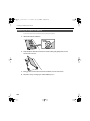
Always turn the phantom power off when connecting
any device other than condenser microphones that
require phantom power. You risk causing damage if
you mistakenly supply phantom power to dynamic
microphones, audio playback devices, or other
devices that don’t require such power. Be sure to
check the specifications of any microphone you
intend to use by referring to the manual that came
with it.
VS-700C Console
(This instrument’s phantom power: 48 V DC, 10mA Max)
......................................................................................................................
VS-700R I/O
Fantom VS
Appendix
5
VS-700_r_e.book 6 ページ 2008年11月20日 木曜日 午後2時28分
IMPORTANT NOTES
Power Supply
301
•
Do not connect this unit to the same electrical outlet that is
being used by an electrical appliance that is controlled by an
inverter (such as a refrigerator, washing machine, microwave
oven, or air conditioner), or that contains a motor. Depending
on the way in which the electrical appliance is used, power
supply noise may cause this unit to malfunction or may
produce audible noise. If it is not practical to use a separate
electrical outlet, connect a power supply noise filter between
this unit and the electrical outlet.
355b
•
360
•
307
•
Before connecting this unit to other devices, turn off the
power to all units. This will help prevent malfunctions and/or
damage to speakers or other devices.
308
•
Although the LCD and LEDs are switched off when the POWER
switch is switched off, this does not mean that the unit has
been completely disconnected from the source of power. If
you need to turn off the power completely, first turn off the
POWER switch, then unplug the power cord from the power
outlet. For this reason, the outlet into which you choose to
connect the power cord’s plug should be one that is within
easy reach and readily accessible.
•
Using the unit near power amplifiers (or other equipment
containing large power transformers) may induce hum. To
alleviate the problem, change the orientation of this unit; or
move it farther away from the source of interference.
401a
•
This device may interfere with radio and television reception.
Do not use this device in the vicinity of such receivers.
352b
•
•
6
Never use benzine, thinners, alcohol or solvents of any kind, to
avoid the possibility of discoloration and/or deformation.
Additional Precautions
553
•
Use a reasonable amount of care when using the unit’s
buttons, sliders, or other controls; and when using its jacks
and connectors. Rough handling can lead to malfunctions.
554
•
Never strike or apply strong pressure to the display.
555
Noise may be produced if wireless communications devices,
such as cell phones, are operated in the vicinity of this unit.
Such noise could occur when receiving or initiating a call, or
while conversing. Should you experience such problems, you
should relocate such wireless devices so they are at a greater
distance from this unit, or switch them off.
•
Do not expose the unit to direct sunlight, place it near devices
that radiate heat, leave it inside an enclosed vehicle, or
otherwise subject it to temperature extremes. Excessive heat
can deform or discolor the unit.
557
354a
•
For everyday cleaning, wipe the unit with a soft, dry cloth or
one that has been slightly dampened with water. To remove
stubborn dirt, use a cloth impregnated with a mild, nonabrasive detergent. Afterwards, be sure to wipe the unit
thoroughly with a soft, dry cloth.
402
352a
•
Depending on the material and temperature of the surface on
which you place the unit, its rubber feet may discolor or mar
the surface.
You can place a piece of felt or cloth under the rubber feet to
prevent this from happening. If you do so, please make sure
that the unit will not slip or move accidentally.
Maintenance
Placement
351
When moved from one location to another where the
temperature and/or humidity is very different, water droplets
(condensation) may form inside the unit. Damage or
malfunction may result if you attempt to use the unit in this
condition. Therefore, before using the unit, you must allow it
to stand for several hours, until the condensation has
completely evaporated.
A small amount of noise may be heard from the display during
normal operation.
556
•
•
When connecting / disconnecting all cables, grasp the
connector itself—never pull on the cable. This way you will
avoid causing shorts, or damage to the cable’s internal
elements.
A small amount of heat will radiate from the unit during
normal operation.
558a
•
To avoid disturbing your neighbors, try to keep the unit’s
volume at reasonable levels. You may prefer to use
headphones, so you do not need to be concerned about those
around you (especially when it is late at night).
VS-700_r_e.book 7 ページ 2008年11月20日 木曜日 午後2時28分
IMPORTANT NOTES
559a
•
Overview
When you need to transport the unit, package it in the box
(including padding) that it came in, if possible. Otherwise, you
will need to use equivalent packaging materials.
562
•
Some connection cables contain resistors. Do not use cables
that incorporate resistors for connecting to this unit. The use
of such cables can cause the sound level to be extremely low,
or impossible to hear. For information on cable specifications,
contact the manufacturer of the cable.
Connections
Copyright
851
•
Recording, duplication, distribution, sale, lease, performance,
or broadcast of copyrighted material (musical works, visual
works, broadcasts, live performances, etc.) belonging to a
third party in part or in whole without the permission of the
copyright owner is forbidden by law.
852a
This product can be used to record or duplicate audio or visual
material without being limited by certain technological copyprotection measures. This is due to the fact that this product is
intended to be used for the purpose of producing original
music or video material, and is therefore designed so that
material that does not infringe copyrights belonging to others
(for example, your own original works) can be recorded or
duplicated freely.
VS-700C Console
•
853
•
VS-700R I/O
Do not use this unit for purposes that could infringe on a
copyright held by a third party. We assume no responsibility
whatsoever with regard to any infringements of third-party
copyrights arising through your use of this unit.
204
* Microsoft and Windows and Windows Vista are registered
trademarks of Microsoft Corporation.
206e
Fantom VS
* The screen shots in this document are used in compliance
with the guidelines of the Microsoft Corporation.
206j
®
®
®
* Windows is known officially as: “Microsoft Windows
operating system.”
233
* ASIO and VST are trademarks of Steinberg Media
Technologies AG.
ADD
220
* All product names mentioned in this document are
trademarks or registered trademarks of their respective
owners.
7
Appendix
* MMP (Moore Microprocessor Portfolio) refers to a patent
portfolio concerned with microprocessor architecture, which
was developed by Technology Properties Limited (TPL).
Roland has licensed this technology from the TPL Group.
VS-700_r_e.book 8 ページ 2008年11月20日 木曜日 午後2時28分
Contents
USING THE UNIT SAFELY............................................................................................................3
IMPORTANT NOTES .....................................................................................................................6
Overview of the VS-700 ......................................................... 13
Main Features ............................................................................................................................. 14
Main Features of the VS-700C Console ..................................................................................14
Main Features of the VS-700R I/O.............................................................................................14
Panel Descriptions .................................................................................................................... 15
VS-700C Console.............................................................................................................................15
Top Panel ......................................................................................................................15
Rear Panel .....................................................................................................................18
VS-700R I/O.......................................................................................................................................19
Front Panel ...................................................................................................................19
Rear Panel .....................................................................................................................21
Top Panel ......................................................................................................................23
Side Panel .....................................................................................................................24
Connections............................................................................... 25
Connections ................................................................................................................................ 26
Turning the Power On ............................................................................................................. 28
VS-700C Console...................................................................... 29
Overview of the VS-700C Console....................................................................................... 30
CHANNEL STRIP Section.......................................................................................................... 31
Channel Fader.............................................................................................................32
FLIP Mode .....................................................................................................................32
Master Fader................................................................................................................32
Adjusting the Touch Sensitivity of the Faders ................................................33
Rotary Encoder (Knob).............................................................................................34
Track Mute....................................................................................................................34
Track Solo (SOLO) ......................................................................................................35
Track Arm (ARM).........................................................................................................35
Strip Select (SEL).........................................................................................................36
8
VS-700_r_e.book 9 ページ 2008年11月20日 木曜日 午後2時28分
Contents
Overview
LED Level Meter..........................................................................................................37
LCD Display ..................................................................................................................37
ASSIGN Button.................................................................................................................................38
How FLIP Mode Affects the [ASSIGN] Button ..................................................39
Rude MUTE/Rude SOLO/Rude ARM Buttons........................................................................40
AUTOMATION Buttons .................................................................................................................41
FADER BANK Buttons ....................................................................................................................42
FADER VIEW Buttons (TRACK, BUS, MAIN, I/O CONTROL) ...............................................43
I/O Control....................................................................................................................44
Specifying the tracks and buses that can be controlled from the VS-700 console 45
Locking a Channel Strip ...............................................................................................................46
To Lock/Unlock a Channel Strip ...........................................................................46
Locked Strip WAI Indication...................................................................................47
Connections
Time Display................................................................................................................................ 48
VS-700C Console
CHANNEL STRIP CONTROL Section (EQ, SEND and ACT)............................................ 49
LCD Display ..................................................................................................................51
EQ Mode........................................................................................................................51
SEND Mode ..................................................................................................................52
ACT Mode .....................................................................................................................53
Transport Section ...................................................................................................................... 54
Starting/Stopping Playback With a Foot Switch ............................................55
VS-700R I/O
PROJECT Section........................................................................................................................ 56
JOG/SHUTTLE/CURSOR Section ........................................................................................... 57
Fantom VS
Transport Mode (Default) .......................................................................................58
Scroll Mode ..................................................................................................................59
Zoom Mode .................................................................................................................60
Select Mode .................................................................................................................61
Edit Mode......................................................................................................................62
Scrub Play Mode.........................................................................................................63
ACCESS PANEL Section (Assignable Buttons) ................................................................. 64
Mapping Assignable ACCESS PANEL Buttons .................................................66
Modifier Buttons ........................................................................................................67
SURROUND Section .................................................................................................................. 68
Appendix
T-Bar Section ............................................................................................................................... 69
AUDIO OUTPUT Section.......................................................................................................... 70
RECORD/EDIT Section.............................................................................................................. 71
Controlling Plug-ins from the VS-700C Console ............................................................ 74
9
VS-700_r_e.book 10 ページ 2008年11月20日 木曜日 午後2時28分
Contents
VS-700R I/O ................................................................................ 77
Connecting Recording Equipment ..................................................................................... 78
Connections to the Analog Jacks .............................................................................................78
Connections to the Digital Connectors..................................................................................79
Switching the Sampling Rate................................................................................................ 80
Setting SONAR’s Sampling Rate................................................................................................81
Audio Clock Source................................................................................................................... 82
Phantom Power ......................................................................................................................... 83
Preamp Parameters .................................................................................................................. 84
Compressor Parameters.......................................................................................................... 85
Direct Monitor Mixer ................................................................................................................ 86
Fantom VS
(Synthesizer) .............................................................................. 87
Inserting the Fantom VS Plug-In.......................................................................................... 88
Fantom VS Editor (Selecting a Sound)............................................................................... 89
Fantom VS Editor (Editing a Sound) ................................................................................... 90
To select a parameter type.....................................................................................90
To edit parameter values ........................................................................................90
To initialize a parameter value..............................................................................90
Overview of the Fantom VS................................................................................................... 91
How the Fantom VS is Organized.............................................................................................91
Classification of Fantom VS Sound Types.........................................................91
About Simultaneous Polyphony ..........................................................................93
About Memory ................................................................................................................................94
Temporary Memory ..................................................................................................94
Non-Rewritable Memory.........................................................................................94
About the Onboard Effects.........................................................................................................95
Effect Types..................................................................................................................95
How Effects Units Work ...........................................................................................95
Creating a Patch......................................................................................................................... 96
How to Make Patch Settings ......................................................................................................96
Functions of Patch Parameters..................................................................................................96
Settings Common to the Entire Patch (GENERAL).........................................96
10
VS-700_r_e.book 11 ページ 2008年11月20日 木曜日 午後2時28分
Contents
Overview
Changing How a Tone Is Sounded (TMT)....................................................... 101
Modifying Waveforms (WG)................................................................................ 105
Modifying the Brightness of a Sound with a Filter (TVF/TVF Env)......... 109
Adjusting the Volume (TVA/TVA Env) ............................................................. 113
Output Settings ....................................................................................................... 116
Modulating Sounds (LFO1/2/Step LFO) ......................................................... 117
Controller-related settings (CTRL) .................................................................... 120
Matrix Control Settings (Matrix Ctrl1–4)......................................................... 121
Connections
Creating a Rhythm Set...........................................................................................................125
VS-700C Console
Functions of Rhythm Set Parameters................................................................................... 125
Making Settings Common to the Entire Rhythm Set (GENERAL).......... 125
Modifying Waveforms (WG)................................................................................ 127
Changing How a Rhythm Tone is Sounded (WMT) .................................... 128
Modifying Pitch (PCH/PCH Env) ........................................................................ 129
Modifying the Brightness of a Sound with a Filter (TVF/TVF Env)......... 131
Adjusting the Volume (TVA/TVA Env) ............................................................. 133
Output Settings ....................................................................................................... 135
Creating a Performance ........................................................................................................136
VS-700R I/O
Adjusting the Parameters of Each Part................................................................................ 136
Parameter List ......................................................................................................... 136
Scale Tune settings ..................................................................................................................... 141
Parameter List .......................................................................................................... 141
MIDI-related settings.................................................................................................................. 142
Parameter List .......................................................................................................... 142
Adding Effects ..........................................................................................................................144
Fantom VS
Turning Effects On and Off....................................................................................................... 144
Applying Effects........................................................................................................................... 145
Signal Flow Diagram (Routing).......................................................................... 145
Functions of Effect Parameters.......................................................................... 146
Specifying the Effect Source ............................................................................... 149
Specifying the multi-effect structure (MFX Structure) .............................. 150
System Settings........................................................................................................................151
Functions of System Parameters ........................................................................................... 151
Appendix
11
VS-700_r_e.book 12 ページ 2008年11月20日 木曜日 午後2時28分
Contents
Appendix ..................................................................................153
VS-700R Block Diagram.........................................................................................................154
Installing the ARX Expansion Board .................................................................................155
Port settings (MIDI input and audio output)..................................................................... 155
Cautions When Installing an Expansion Board................................................................. 155
How to Install an Expansion Board ....................................................................................... 156
Removing an Expansion Board .............................................................................................. 158
Installation de la carte d’expansion..................................................................................159
Precautions a prendre lors de l’installation d’une carte d’expansion ...................... 159
Installation d’une carte d’expansion .................................................................................... 160
Retrait d’une carte d’expansion ............................................................................................. 162
Attaching the Rackmount Brackets ..................................................................................163
Using only the VS-700C Console (Standalone Mode) ................................................164
Using only the VS-700R I/O..................................................................................................165
Connecting Two VS-700R I/O Units ..................................................................................166
Connecting an EDIROL DV-7DL (Video Control) ..........................................................168
Connecting the EDIROL DV-7DL and VS-700C............................................. 168
To Enable Video Control....................................................................................... 168
About V-LINK.............................................................................................................................169
Troubleshooting ......................................................................................................................171
Problems with the VS-700R Unit............................................................................................ 171
Problems with the VS-700C Unit ........................................................................................... 171
Specifications............................................................................................................................172
Index ............................................................................................................................................175
Index (Fantom VS)...................................................................................................................179
12
VS-700_r_e.book 13 ページ 2008年11月20日 木曜日 午後2時28分
Overview of the VS-700
13
VS-700_r_e.book 14 ページ 2008年11月20日 木曜日 午後2時28分
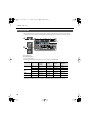
Main Features
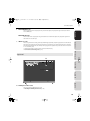
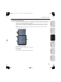
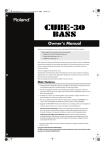
Main Features of the VS-700C Console
fig.panel-vs-700.eps
•
•
•
•
•
•
•
•
•
Control of mix and plug-in parameters with real-time visual feedback
Touch-sensitive motorized faders
Control over SONAR, plug-in effects and soft synths
Many buttons to trigger SONAR commands plus 16 assignable buttons
Multiple modifier buttons to extend the functionality of other controls
Tape-style transport controls
Jog/shuttle wheel with cursor-style buttons for scrubbing, editing, zooming and scrolling
Surround joystick panner
Meter displays with track names and parameters
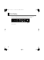
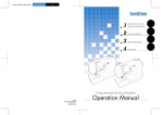
Main Features of the VS-700R I/O
fig.panel-vs-700r.eps
• 19-in/24-out USB 2.0 audio interface
• 24-bit 192 kHz high quality audio
• Eight channels of preamps/compressors built-in
• Built-in Fantom VS synthesizer
• Single slot for ARX series expansion boards
14
VS-700_r_e.book 15 ページ 2008年11月20日 木曜日 午後2時28分
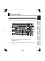
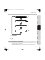
Panel Descriptions
Overview
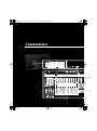
VS-700C Console
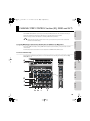
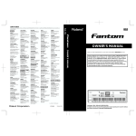
Top Panel
Connections
fig.panel-vs-700c-top.eps
A
B
C
VS-700C Console
I
J
D
K
VS-700R I/O
L
E
F
G H
M N
Fantom VS
A. LCD Display
The VS-700C features three 2-line LCD displays. The left LCD display shows information about the CHANNEL STRIP
CONTROL section and the other two LCD displays show information about the channel strips.
➔ “LCD Display” (p. 37), (p. 51)
Appendix
B. T-Bar
The T-Bar lets you control the Front-Rear Balance parameter in the surround panner, an ACT parameter or the X-Ray
opacity.
➔ “T-Bar Section” (p. 69)
15
VS-700_r_e.book 16 ページ 2008年11月20日 木曜日 午後2時28分
Panel Descriptions
C. Time Display
The VS-700C Console displays the project’s current Now time in the top right corner. You can switch the display
between SMPTE and Bars|Beats time by pressing the [TIME CODE] button. The default view is Bars|Beats.
➔ “Time Display” (p. 48)
D. CHANNEL STRIP CONTROL Section
The CHANNEL STRIP CONTROL section lets you control EQ and SEND parameters for the selected channel strip, as
well as ACT parameters for the track, bus, effect plug-in or soft synth that has focus in SONAR.
There are 12 rotary encoders and 4 buttons to control EQ, SEND and ACT parameters.
➔ “CHANNEL STRIP CONTROL Section (EQ, SEND and ACT)” (p. 49)
E. ACCESS PANEL Section
The ACCESS PANEL section provides 16 assignable buttons that you can configure to control different functions in
SONAR. There are also 4 modifier buttons that are used to extend the functionality of other VS-700 hardware
controls. The modifier buttons are not assignable.
➔ “ACCESS PANEL Section (Assignable Buttons)” (p. 64)
F. Channel Strips
The Channel Strip section provides eight motorized fader strips with identical controls. You use the channel strips to
control up to eight tracks or buses at a time and you can easily switch between different banks of tracks or buses.
➔ “CHANNEL STRIP Section” (p. 31)
G. RECORD/EDIT Section
The RECORD/EDIT section lets you control punch-recording and looping, select clips or edit regions, and insert or
move markers.
➔ “RECORD/EDIT Section” (p. 71)
H. Transport Section
The transport section provides standard control of RTZ (return to zero), Rewind, Fast Forward, Go to end, Stop, Play
and Record.
➔ “Transport Section” (p. 54)
I.
AUDIO OUTPUT Section
The AUDIO OUTPUT section lets you control the volume of the MONITOR output and each headphone output. You
can also mute the MONITOR output and assign each headphone to monitor the MAIN/SUB output.
➔ “AUDIO OUTPUT Section” (p. 70)
16
VS-700_r_e.book 17 ページ 2008年11月20日 木曜日 午後2時28分
Panel Descriptions
J.
SURROUND Section
The SURROUND section lets you control surround bus parameters on the selected channel strip.
Overview
➔ “SURROUND Section” (p. 68)
K. PROJECT Section
The PROJECT sections provides convenient access to frequently used commands that normally require a keyboard or
mouse, such as Save, Undo/Redo, OK/ENTER and Cancel.
➔ “PROJECT Section” (p. 56)
Connections
L. Jog/Shuttle Wheel
The VS-700C Console jog/shuttle is a combo wheel with cursor buttons, which lets you perform edit, zoom, scroll and
select operations.
➔ “JOG/SHUTTLE/CURSOR Section” (p. 57)
VS-700C Console
M. AUX IN Jack (Front Panel)
This is a mic/guitar input jack located on the front panel of the console. It supports mic input when the switch is at
“NORMAL,” or guitar input when the switch is at [Hi-Z]. Use the SENS knob to adjust the input level. The input signal is
output directly to the “VS-700 AUX” port of the audio driver.
➔ “Connections to the Analog Jacks” (p. 78)
N. PHONES Jacks (Front Panel)
VS-700R I/O
These are two headphone jacks located on the front panel of the console. They monitor either the MAIN port or SUB
port, and each has a switch on the console to select the signal that it will monitor. The volume can be adjusted
independently for each jack.
➔ “AUDIO OUTPUT Section” (p. 70)
Fantom VS
Appendix
17
VS-700_r_e.book 18 ページ 2008年11月20日 木曜日 午後2時28分
Panel Descriptions
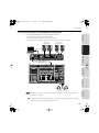
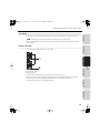
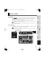
Rear Panel
fig.panel-vs-700c-rear.eps
A B C
D E
F
G
A. TO I/O Connector
Use the dedicated cable to connect the VS-700C Console to the VS-700R I/O unit. Do not use any cable other than the
dedicated cable.
➔ “Connecting Your Computer and Sound Reinforcement Equipment” (p. 27)
B. USB Connector
By connecting the USB connector of the console directly to your computer (without using the VS-700R I/O unit), you
can use the console as a control surface.
➔ “Using only the VS-700C Console (Standalone Mode)” (p. 164)
C. SETTING DIP Switches
Change the settings of these switches if you have connected the console directly to your computer (without using
the VS-700R I/O unit).
➔ “Using only the VS-700C Console (Standalone Mode)” (p. 164)
D. FOOT SW Jacks
Here you can connect two foot switches.
➔ “Starting/Stopping Playback With a Foot Switch” (p. 55)
E. LCD CONTRAST Knob
This adjusts the brightness of the LCD display.
F. AC Inlet
Connect the included power cord to this inlet.
➔ “Connecting the Power Cord” (p. 26)
G. POWER ON Switch
Press to turn the power on/off.
➔ “Turning the Power On” (p. 28)
18
VS-700_r_e.book 19 ページ 2008年11月20日 木曜日 午後2時28分
Panel Descriptions
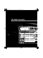
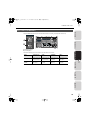
VS-700R I/O
Overview
Front Panel
fig.panel-vs-700r-front.eps
A
B
G
Connections
C
D
E
H
I
J
K
VS-700C Console
F
A. USB Indicator
This will light when the console is connected via USB to your computer.
➔ “If the USB indicator of the VS-700R I/O unit isn’t lit” (p. 28)
B. CONSOLE Indicator
VS-700R I/O
This will light when the VS-700C console is connected via the dedicated cable and has been detected. If the cable is
connected but the console has not been detected, this will blink.
➔ “If the I/O indicator of the VS-700C console or the CONSOLE indicator of the VS-700R I/O unit is blinking”
(p. 28)
C. MIDI IN Indicator
This will light when MIDI messages are received at the MIDI IN connector.
Fantom VS
MIDI OUT Indicator
This will light when MIDI messages are transmitted from the MIDI OUT connector.
D. DIGITAL IN Indicators
These will light when audio signals are input to DIGITAL IN 1 or 2.
Appendix
DIGITAL OUT Indicators
These will light when audio signals are output from DIGITAL OUT 1 or 2.
19
VS-700_r_e.book 20 ページ 2008年11月20日 木曜日 午後2時28分
Panel Descriptions
E. SAMPLE RATE Knob
This specifies the sample rate. In order for this setting to be reflected by the system, you must cycle the power to the
VS-700R. If you need to synchronize with another digital device, you must first set this knob to the same sample rate
as the master device.
➔ “Switching the Sampling Rate” (p. 80)
F. SYNC Indicator
This indicates the audio clock status.
➔ “Audio Clock Source” (p. 82)
G. INPUT Indicators
These indicate the input levels from the INPUT connectors and AUX connectors.
If PEAK has lit, the sound has distorted.
If the cooling fan (p. 24) has stopped turning because of a malfunction, all indicators will blink. For details,
refer to “Troubleshooting” (p. 171).
H. MONITOR MAIN Indicators
These will light when audio signals are output from MONITOR MAIN.
MONITOR SUB Indicators
These will light when audio signals are output from MONITOR SUB.
I.
OUTPUT 1–10 Indicators
These will light when audio signals are output from OUTPUT 1–10.
J.
POWER ON Switch
Press this to turn the power on/off.
➔ “Turning the Power On” (p. 28)
K. Rackmount brackets
If you want to install the system in a 19” rack, attach the included rackmount brackets.
➔ “Attaching the Rackmount Brackets” (p. 163)
20
VS-700_r_e.book 21 ページ 2008年11月20日 木曜日 午後2時28分
Panel Descriptions
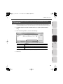
Rear Panel
Overview
fig.panel-vs-700r-rear.eps
A
C
D
E
F
H
I
Connections
B
G
J
A. TO CONSOLE Connector
VS-700C Console
Use the dedicated cable to connect this to the VS-700C console. Do not use any cable other than the dedicated cable.
➔ “Connecting Your Computer and Sound Reinforcement Equipment” (p. 27)
B. AC Inlet
Connect the included power cord to this inlet.
➔ “Connecting the Power Cord” (p. 26)
* For details on the power supply and power consumption, refer to “Specifications” (p. 172).
VS-700R I/O
C. MIDI IN Connector
This is a MIDI input connector. You can connect your MIDI keyboard or MIDI controller here. This can also be used as
an MTC input. In the driver, this will appear as “IO MIDI (VS-700).”
MIDI OUT Connector
Fantom VS
This is a MIDI output connector. You can connect an external MIDI sound module here. In the driver, this will appear
as “IO MIDI (VS-700).”
D. USB Connector
Connect this to a computer that supports USB 2.0.
➔ “Connecting Your Computer and Sound Reinforcement Equipment” (p. 27)
Appendix
At first, before connecting anything to this connector, you must install the driver as described in “Getting
Started” (separate document). After the driver has been installed and connections have been completed
correctly, the USB indicator will light. If the USB indicator isn’t lit, the driver has not been installed correctly.
Refer to the troubleshooting section of “Getting Started,” and install the driver once again.
21
VS-700_r_e.book 22 ページ 2008年11月20日 木曜日 午後2時28分
Panel Descriptions
E. DIGITAL 2 OUT Connector
This is an ADAT output connector. You can connect it to an ADAT device and output up to eight channels of audio.
DIGITAL 2 IN Connector
This is an ADAT input connector. It allows up to eight channels of input. The input signals are output directly to the
“VS-700 IN DIGITAL2 1-2” – “VS-700 IN DIGITAL2 7-8” ports of the audio driver.
➔ “Connections to the Digital Connectors” (p. 79)
F. DIGITAL 1 AES/EBU OUT Connector
This is an AES/EBU format two-channel (stereo) digital output. The same signal is also output to the COAXIAL OUT
connector. This will output the signal of the audio driver’s “VS-700 OUT DIGITAL1” port.
DIGITAL 1 AES/EBU IN Connector
This is an AES/EBU format two-channel (stereo) digital input. This is switched with the COAXIAL IN (S/PDIF)
connector. The input signal is output directly to the audio driver’s “VS-700 IN DIGITAL1” port.
➔ “Connections to the Digital Connectors” (p. 79)
DIGITAL 1 COAXIAL OUT Connector
This is an S/PDIF format two-channel (stereo) digital output. The same signal is also output to the AES/EBU connector.
This will output the signal of the audio driver’s “VS-700 OUT DIGITAL1” port.
DIGITAL 1 COAXIAL IN Connector
This is an S/PDIF format two-channel (stereo) digital input. This is switched with the AES/EBU connector. The input
signal is output directly to the audio driver’s “VS-700 IN DIGITAL1” port.
➔ “Connections to the Digital Connectors” (p. 79)
G. WORDCLOCK IN Connector
This is a WORDCLOCK input connector.
For details on checking and selecting the clock source, refer to “Audio Clock Source” (p. 82).
WORDCLOCK OUT Connector
This is a WORDCLOCK output connector. It outputs a clock at all times.
H. OUTPUT 1–10 Jacks
These are ten channels of audio output connectors. They allow a broad range of connections, such as for multioutput in a surround system, or as sends for outboard effects. These are balanced outputs. They output the signals of
the audio driver’s “1-2 (VS-700)” – “VS-700 OUT 9-10” ports.
22
VS-700_r_e.book 23 ページ 2008年11月20日 木曜日 午後2時28分
Panel Descriptions
I.
MONITOR MAIN Jacks
Overview
These are the main monitor output jacks. They are balanced outputs. They output the signals of the audio driver’s
“VS-700 MAIN” port.
MONITOR SUB Jacks
These are sub-monitor output jacks. They provide balanced or unbalanced output. They output the signals of the
audio driver’s “VS-700 SUB” port.
INPUT 1–8 Jacks
Connections
J.
These are eight channels of analog audio input. Both XLR type (balanced) and phone type (balanced or unbalanced)
input jacks are provided. A mic preamp and compressor are provided on each channel. Phantom power is provided
to the XLR jacks (switchable for each channel). The input signals are output directly to the audio driver’s “VS-700 IN 12” – “VS-700 IN 7-8” ports.
* The XLR jacks and phone jacks cannot be connected simultaneously.
VS-700C Console
➔ “Connections to the Analog Jacks” (p. 78)
Top Panel
fig.panel-vs-700r-top.eps
A
VS-700R I/O
Fantom VS
Appendix
A. ARX Expansion Board Slot
Here you can install an ARX expansion board.
➔ “Installing the ARX Expansion Board” (p. 155)
23
VS-700_r_e.book 24 ページ 2008年11月20日 木曜日 午後2時28分
Panel Descriptions
Side Panel
fig.panel-vs-700r-side.eps
A
C
B
A
A. Rackmount Brackets
If you want to install the system in a 19” rack, attach the included rackmount brackets.
➔ “Attaching the Rackmount Brackets” (p. 163)
B. Cooling Fan Intake Vent
C. Cooling Fan Exhaust Vent
The VS-700R contains a cooling fan that prevents internal overheating. External air is drawn in through the intake
vent, then is expelled from the exhaust vent, while carrying along with it the heat that has accumulated inside the
unit.
Do not block the cooling fan intake vent or exhaust vent. Doing so will cause the internal temperature to rise,
possibly causing heat-related malfunctions.
If you install the system in a 19" rack, you must leave at least 1 cm of space outside the intake vent and exhaust
vent.
24
VS-700_r_e.book 25 ページ 2008年11月20日 木曜日 午後2時28分
Connections
25
VS-700_r_e.book 26 ページ 2008年11月20日 木曜日 午後2時28分
Connections
Before connecting the VS-700C and VS-700R to your computer, you must install the VS-700 driver
in your computer as described in “Getting Started” (separate document). The VS-700C and
VS-700R will not operate correctly unless the driver is installed in your computer.
Connecting the Power Cord
• Connect the power cord.
fig.VS-700-connect04-e.eps
VS-700C Rear Panel
to Power Outlet
Power Cord
VS-700R Rear Panel
Power Cord
26
to Power Outlet
VS-700_r_e.book 27 ページ 2008年11月20日 木曜日 午後2時28分
Connections
Connecting Your Computer and Sound Reinforcement Equipment
Overview
• Use the included dedicated cable to connect the VS-700R and VS-700C.
• Use a USB cable to connect the VS-700R to your computer.
• Connect your headphones, speakers, or other device to the VS-700.
* This package does not include sound reinforcement equipment such as headphones or speakers.
fig.basic-e.eps
Monitor (sub)
amplified speakers
Monitor (main)
amplified speakers
Connections
USB cable (included)
VS-700C Console
VS-700R Rear Panel
Dedicated connection
cable (included)
VS-700R I/O
Fantom VS
VS-700C
Stereo
Headphones 2
Appendix
Stereo
Headphones 1
The VS-700 may not be recognized correctly if you’re using a USB hub. In this case, connect it directly to a
USB port on your computer.
921
To prevent malfunction and/or damage to speakers or other devices, always turn down the volume, and turn
off the power on all devices before making any connections.
27
VS-700_r_e.book 28 ページ 2008年11月20日 木曜日 午後2時28分
Turning the Power On
941
Once the connections have been completed (p. 26), turn on power to your various devices in the order
specified. By turning on devices in the wrong order, you risk causing malfunction and/or damage to speakers
and other devices.
945
If you need to turn off the power completely, first turn off the POWER switch, then unplug the power cord from
the power outlet. Refer to “Power Supply” (p. 6).
1. Minimize the VS-700C’s [AUDIO OUTPUT]
VS-700C Top Panel
knobs (three locations).
2. Start up your computer.
3. Turn on the power switch of the VS-700C.
VS-700C Rear Panel
Power On
4. Turn on the power switch of the VS-700R.
VS-700R Front Panel
Power On
5. Turn on the power switch of your monitor speakers.
Due to a circuitry-protection feature, the VS-700R requires a few moments after power-up before it is ready
for normal operation. If the connections are correct, the VS-700R’s USB indicator will light.
If the USB indicator of the VS-700R I/O unit isn’t lit
If the USB indicator of the VS-700R isn’t lit, the driver has not been installed correctly. Refer to the
“Troubleshooting” chapter in “Getting Started.”
If the I/O indicator of the VS-700C console or the CONSOLE indicator of the VS-700R I/O unit is blinking
Check the following points.
• Are the VS-700C and VS-700R powered up?
• Are the VS-700C and VS-700R correctly connected via the dedicated cable?
• Is the VS-700 R I/O unit connected to your computer via a USB cable, and is the USB indicator of the
VS-700R I/O unit lit?
28
VS-700_r_e.book 29 ページ 2008年11月20日 木曜日 午後2時28分
VS-700C Console
29
VS-700_r_e.book 30 ページ 2008年11月20日 木曜日 午後2時28分
Overview of the VS-700C Console
The VS-700C Console consist of different sections that are used to control SONAR, including:
• Nine touch sensitive motorized faders
• User definable buttons to map via ACT
• Dedicated section for controlling plug-ins and track/bus parameters
• Jog/Shuttle wheel
• Transport controls
• Surround joystick panner
fig.panel-VS-700c-top.eps
A
B
C
I
J
D
K
L
E
F
A. LCD display (p. 37, p. 51)
B. T-bar (p. 69)
C. Time display (p. 48)
D. CHANNEL STRIP CONTROL section (p. 49)
E. ACCESS PANEL section (p. 64)
F. Channel strips (p. 31)
G. RECORD/EDIT section (p. 71)
H. Transport section (p. 54)
I. AUDIO OUTPUT section (p. 70)
J. SURROUND section (p. 68)
K. PROJECT section (p. 56)
L. Jog/Shuttle wheel (p. 57)
M. AUX IN Jack (Front Panel) (p. 78)
N. PHONES Jack (Front Panel) (p. 70)
30
G H
M N
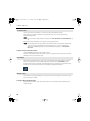
VS-700_r_e.book 31 ページ 2008年11月20日 木曜日 午後2時28分
CHANNEL STRIP Section
Overview
The Channel Strip section provides eight touch sensitive motorized fader strips with identical controls. You use the
channel strips to control up to eight tracks or buses at a time and you can easily switch between different banks of
tracks or buses (refer to “FADER BANK Buttons” (p. 42)). That is, although there are only eight physical channel
strips, you can switch them to control an unlimited number of tracks and buses in your project. The channel strips
always show the status of the current set of eight channels.
Connections
The Channel Strip section also provides a single motorized Master fader, which is used to control the level of the
master bus.
You use the [FADER BANK] and [FADER VIEW] buttons to assign tracks and buses to the channel strips (refer to
“FADER BANK Buttons” (p. 42) and “FADER VIEW Buttons (TRACK, BUS, MAIN, I/O CONTROL)” (p. 43)). The
assigned channel strip names are displayed on the LCD displays.
fig.2.eps
A. LCD display (p. 37)
B. Rotary encoder (p. 34)
A
VS-700C Console
C. [MUTE] button (p. 34)
D. [SOLO] button (p. 35)
E. [ARM] button (arm for recording) (p. 35)
F. [SEL] button (Select) (p. 36)
G. LED level meter (p. 37)
H. Channel fader (p. 32)
VS-700R I/O
B
C
D
E
F
G
H
Fantom VS
Appendix
31
VS-700_r_e.book 32 ページ 2008年11月20日 木曜日 午後2時28分
CHANNEL STRIP Section
Channel Fader
Use the touch sensitive motorized faders to control levels of audio tracks, MIDI tracks and buses.
When tracks/buses are armed for automation recording, the faders allow you to record automation data by
touching/releasing the faders.
For more information about automation recording, refer to “Rude MUTE/Rude SOLO/Rude ARM Buttons” (p.
40).
During playback, the motorized faders move in response to existing automation data.
The motorized faders are very quiet, but there may be situations when you want total silence when mixing
a soft piece of music or recording with a microphone near the VS-700C Console. To disable the fader
motors, press [COMMAND]+[I/O] buttons to open the VS-700 property page, then click Disable Fader
Movements.
To Revert a Fader to Its Previous Value
Hold the [COMMAND] modifier button and touch/move a fader.
The top row on the LCD display shows “Revert”. After 1/2 second, the parameter reverts to its previous value and the
LCD display reverts to its previous display mode.
FLIP Mode
When FLIP mode is enabled, the functions of the rotary encoders and faders are swapped, allowing you to use the
faders for more detailed control of the currently assigned encoder function (refer to “ASSIGN Button” (p. 38)).
By default, the fader value is only displayed on the LCD display when you move the fader. To toggle between always
showing rotary encoder values or fader values on the LCD display, press [SHIFT]+[FLIP] buttons.
fig.2-2.eps
Master Fader
The master fader controls the first available bus in your project, however it can be assigned to control the level of any
stereo or surround bus in SONAR.
To Assign a Bus to the Master Fader
Drag the WAI strip in SONAR to assign a bus to the master fader. For more information about the WAI strip, see the
SONAR online Help.
32
VS-700_r_e.book 33 ページ 2008年11月20日 木曜日 午後2時28分
CHANNEL STRIP Section
Overview
Adjusting the Touch Sensitivity of the Faders
Depending on the conditions in which you use the VS-700, the touch sensitivity of the faders may not
work as you expect, or the motor may operate incorrectly when you’re operating the fader. If this occurs,
adjust the touch sensitivity as follows.
1. Close SONAR.
Connections
2. While holding down the [SHIFT] button and [CTRL] button, press the [MUTE] button of
the audio output section.
The current sensitivity setting will be shown in the LCD display, and you’ll be in sensitivity adjustment
mode.
fig.7a.eps_50
Fader Touch Sensitivity:100
OFF
OFF
OFF
OFF
Rotate JOG to adjust sensitivity
OFF
OFF
OFF
OFF
VS-700C Console
A
OFF
B
A. Fader Touch Sensitivity (0–127)
VS-700R I/O
Higher values will increase the touch sensitivity; lower values will make it less responsive. At a
setting of 0, touch sensitivity will be disabled.
B. Touch sensitivity monitor
This will indicate “ON” if touch sensitivity activates when you touch the fader, and will return to
“OFF” when you remove your finger.
3. Turn the jog wheel to adjust “Fader Touch Sensitivity” in a range of 0–127.
Fantom VS
Adjust this setting so that the touch sensitivity monitor indication in the LCD display changes from
“OFF” to “ON” when you touch each fader. Increase the value if the indication fails to turn “ON” when
you touch a fader; decrease the value if the indication turns “ON” when you merely bring your finger
near the fader.
The “Fader Touch Sensitivity” setting is common to all faders.
Appendix
4. When you’ve finished making settings, hold down the [SHIFT] button and [CTRL]
button and press the [MUTE] button of the audio output section.
You’ll exit sensitivity adjustment mode, and return to the previous screen.
33
VS-700_r_e.book 34 ページ 2008年11月20日 木曜日 午後2時28分
CHANNEL STRIP Section
Rotary Encoder (Knob)
The rotary encoders work in conjunction with the [ASSIGN] button to allow tactile control over various track, bus and
main parameters. All eight rotary encoders always control the same parameter type across different tracks/buses.
The rotary encoders control pan by default, but can be configured to control other channel parameters by pressing
the [ASSIGN] button. For details on the [ASSIGN] button, refer to “ASSIGN Button” (p. 38).
You can push on the top of the rotary encoder to reset the parameter to its default and/or unity setting (C for pan
and 0 dB for gains).
When FLIP mode is enabled, the functions of the rotary encoders and faders are swapped, allowing you to use the
faders for more detailed control of the currently assigned encoder function.
To Revert a Rotary Encoder to Its Previous Value
Hold the [COMMAND] modifier button and press/turn a rotary encoder.
The top row on the LCD display shows “Revert.” After 1/2 second, the parameter reverts to its previous value and the
LCD display reverts to its previous display mode.
Track Mute
Use the [MUTE] button to mute/unmute the assigned track or bus. When the channel is muted, the [MUTE] button is
lit.
When one or more channels are muted, the [Rude MUTE] button is lit as a convenient reminder. You can press the
[Rude MUTE] button to quickly unmute all channels. For more information about Rude Mute, refer to “Rude MUTE/
Rude SOLO/Rude ARM Buttons” (p. 40).
The modifier buttons (p. 67) can be used to extend the functions as follows.
34
FADER VIEW mode
MUTE
SHIFT + MUTE
ALT+MUTE
TRACK
Mute/unmute
Toggle input monitoring
Automated mute
(when Automation Write is
enabled)
BUS
Mute/unmute
(Reserved)
(Reserved)
MAIN
Mute/unmute
(Reserved)
(Reserved)
VS-700_r_e.book 35 ページ 2008年11月20日 木曜日 午後2時28分
CHANNEL STRIP Section
Track Solo (SOLO)
Overview
Use the [SOLO] button to solo/unsolo the assigned track or bus. When the channel is soloed, the [SOLO] button is lit.
When one or more channels are soloed, the [Rude SOLO] button is lit as a convenient reminder. You can press the
[Rude SOLO] button to quickly unsolo all channels. For more information about Rude SOLO, refer to “Rude MUTE/
Rude SOLO/Rude ARM Buttons” (p. 40).
The modifier buttons (p. 67) can be used to extend the functions as follows.
SOLO
SHIFT + SOLO
TRACK
Solo/unsolo
Enable/Disable Solo Override
BUS
Solo/unsolo
(Reserved)
MAIN
(Reserved)
(Reserved)
Connections
FADER VIEW mode
VS-700C Console
Track Arm (ARM)
Use the [ARM] button to arm the track for recording. When the track is armed for recording, the [ARM] button is lit.
When one or more channels are armed for recording, the [Rude ARM] button is lit as a convenient reminder. You can
press the [Rude ARM] button to quickly disarm all tracks. For more information about Rude ARM, refer to “Rude
MUTE/Rude SOLO/Rude ARM Buttons” (p. 40).
The modifier buttons (p. 67) can be used to extend the functions as follows.
ARM
TRACK
Arm for recording
BUS
(Reserved)
MAIN
(Reserved)
VS-700R I/O
FADER VIEW mode
Fantom VS
Appendix
35
VS-700_r_e.book 36 ページ 2008年11月20日 木曜日 午後2時28分
CHANNEL STRIP Section
Strip Select (SEL)
Use the [SEL] button to activate the CHANNEL STRIP CONTROL section for the selected channel, which allows you to
control EQ and Send parameters for that channel.
The eight [SEL] buttons are mutually exclusive, so only one channel at a time can be selected. When enabled, the
[SEL] button stays lit.
The modifier buttons (p. 67) can be used to extend the functions as follows.
The [SEL] button is not bi-directional. Changing the current track in SONAR will not change the selected
channel on the VS-700C Console.
fig.4.eps
36
Button
Explanation
Default (no modifier button)
Activates the CHANNEL STRIP CONTROL section for the selected channel. Also
sets the current track in SONAR if FADER VIEW is assigned to TRACK.
CTRL+SEL
Enable Plug-in mode. For more information, refer to “Controlling Plug-ins
from the VS-700C Console” (p. 74).
SHIFT+SEL
Locks/unlocks the channel strip to the corresponding track/bus in SONAR.
(p. 46)
COMMAND+SEL
Toggles a global enable state for locking. If you have strips locked, you can
disable and re-enable locking and the same strips will be locked.
VS-700_r_e.book 37 ページ 2008年11月20日 木曜日 午後2時28分
CHANNEL STRIP Section
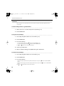
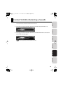
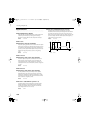
LED Level Meter
Overview
The LED level meter displays the channel’s current peak volume level. The indicated levels are 0 dB (peak), -3 dB, -12
dB, -24 dB and -48 dB.
fig.6.eps
Connections
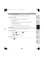
LCD Display
VS-700C Console
Each channel strip (including the master fader) has a two-line LCD display that displays track information based on
which ASSIGN function is selected.
fig.7.eps
A
Bass1
30% R
C
Guitar1
25% L
Encoder
Pan
VS-700R I/O
B
Drum01
C
D
A. Track/bus/main name
B. Value of parameter that is assigned to the rotary encoder
C. Encoder or IO Cntrl (based on “I/O Control” (p. 44))
Fantom VS
D. Name of parameter that is assigned to the rotary encoder (Pan, SendVol, In or Out)
Appendix
37
VS-700_r_e.book 38 ページ 2008年11月20日 木曜日 午後2時28分
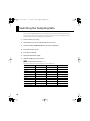
CHANNEL STRIP Section
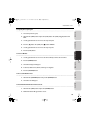
ASSIGN Button
Use the [ASSIGN] button to change the parameter that’s assigned to the rotary encoders of the channel strips. The
available functions vary depending on which [FADER VIEW] button (TRACK, BUS, MAIN or I/O CONTROL) is selected.
fig.8.eps
A
C
B
A. [ASSIGN] button
B. [FADER VIEW] buttons
C. [I/O CONTROL] button
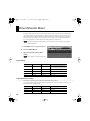
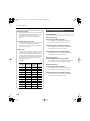
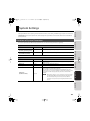
The following table shows which parameter types are available for each FADER VIEW.
FADER VIEW
Channel strip
type
ASSIGN
function1
(default)
ASSIGN
function2
ASSIGN
function3
ASSIGN
function4
Audio
Pan
Send 1 Volume
Input
Output
MIDI
Pan
Chorus Send
MIDI Channel
Output
Stereo
Pan
Send 1 Volume
Send 1 Pan
Output
TRACK
BUS
Surround
(Reserved)
Send 1 Volume
(Reserved)
Output
MAIN
Audio
(Reserved)
(Reserved)
(Reserved)
(Reserved)
I/O CONTROL
(audio)
Mic Pre Gain
(p. 84)
Threshold
(p. 85)
Attack (p. 85)
Release (p. 85)
* When the I/O CONTROL mode, you can switch On/Off of PAD (p. 84) by pressing the rotary encoder.
38
VS-700_r_e.book 39 ページ 2008年11月20日 木曜日 午後2時28分
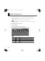
CHANNEL STRIP Section
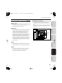
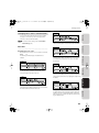
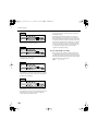
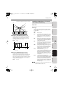
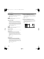
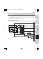
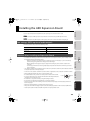
The illustration below shows how the parameter will be switched if FADER VIEW is set to TRACK.
fig.9.eps
Bass1
0dB
Guitar1
0.5dB
Drum01
-9.0dB
Encoder
Send Vol
Bass1
-7001-2
Guitar1
-7003-4
Drum01
-7005-6
Encoder
In
Bass1
Master
Guitar1
Master
Drum01
Bus1
Encoder
Out
1
2
3
4
VS-700R I/O
Encoder
Pan
VS-700C Console
Drum01
C
Connections
Guitar1
25% L
Overview
Bass1
30% R
1. Pan (default display)
Fantom VS
2. Send Volume/Chorus Send
3. Input
4. Output
Appendix
How FLIP Mode Affects the [ASSIGN] Button
When FLIP mode is enabled, the [ASSIGN] button is disabled, regardless of which FADER VIEW type is selected. In FLIP
mode, the faders and rotary encoders swap functions.
When [SHIFT]+[FLIP] buttons are pressed, the values of the faders are shown on the LCD display, but the faders and
rotary encoders do not swap functions.
39
VS-700_r_e.book 40 ページ 2008年11月20日 木曜日 午後2時28分
CHANNEL STRIP Section
Rude MUTE/Rude SOLO/Rude ARM Buttons
The [Rude MUTE], [Rude SOLO] and [Rude ARM] buttons let you mute or unmute, solo or unsolo, arm or disarm all
channels simultaneously.
When one or more channels are muted, soloed or armed for recording, the corresponding [Rude] button is lit as a
convenient reminder.
Since the channel strips only show the status of the current set of eight channels, the [Rude MUTE], [Rude
SOLO] and [Rude ARM] buttons serve as a reminder that other non-visible channels might be muted/soloed/
armed.
fig.10.eps
A
B
C
A. [Rude MUTE] button
B. [Rude SOLO] button
C. [Rude ARM] button
The modifier buttons (p. 67) can be used to extend the functions as follows.
40
Button
Default function
SHIFT+
CTRL+
Rude MUTE
Mute/unmute all tracks
(Reserved)
(Reserved)
Rude SOLO
Solo/unsolo all tracks
Toggle Dim Solo mode
Toggle Exclusive Solo
mode
Rude ARM
Arm/disarm all tracks for
recording
(Reserved)
(Reserved)
VS-700_r_e.book 41 ページ 2008年11月20日 木曜日 午後2時28分
CHANNEL STRIP Section
AUTOMATION Buttons
Overview
The [AUTOMATION] buttons let you enable/disable automation recording and playback for all channels.
fig.11.eps
A
Connections
B
A. [WRITE/OFF] button
VS-700C Console
B. [OFFSET] button
The modifier buttons (p. 67) can be used to extend the functions as follows.
Default function
SHIFT+
COMMAND+
SHIFT+
COMMAND+
WRITE/OFF
Enable/disable write
automation for
selected track/bus
Enable/disable read
automation for
selected track/bus
Enable/disable write
automation for all
tracks/buses.
Enable/disable read
automation for all
tracks/buses.
OFFSET
Enable/disable
Offset mode
Take an automation
snapshot
(Reserved)
(Reserved)
VS-700R I/O
Button
Fantom VS
Appendix
41
VS-700_r_e.book 42 ページ 2008年11月20日 木曜日 午後2時28分
CHANNEL STRIP Section
FADER BANK Buttons
The VS-700C Console has eight physical channel strips that can be used to control up to eight tracks, buses or mains
at a time. You use the [FADER BANK] buttons to switch between different banks of tracks/buses/mains, which allows
the channel strips to control a different set of tracks/buses/mains.
fig.12.eps
A
B
A. [+8] button
B. [-8] button
The modifier buttons (p. 67) can be used to extend the functions as follows.
42
Button
Default function
SHIFT+
+8
Shift currently viewed channels forward/up in
banks of eight
Shift currently viewed channels forward/up in
banks of one
-8
Shift currently viewed channels backward/
down in banks of eight
Shift currently viewed channels back/down in
banks of one
VS-700_r_e.book 43 ページ 2008年11月20日 木曜日 午後2時28分
CHANNEL STRIP Section
FADER VIEW Buttons (TRACK, BUS, MAIN, I/O CONTROL)
Overview
You use the [FADER VIEW] buttons to specify what channel type (tracks, buses or mains) is assigned to the channel
strips.
fig.13.eps
Connections
VS-700C Console
The modifier buttons (p. 67) can be used to extend the functions as follows.
Default function
SHIFT+
COMMAND+
TRACK
Assign the channel strips to tracks
Enable/disable Layer
mode
(Reserved)
BUS
Assign the channel strips to buses
(Reserved)
(Reserved)
MAIN
Assign the channel strips to mains
(Reserved)
(Reserved)
I/O CONTROL
Enable control of VS-700R I/O from
rotary encoders
(Reserved)
Open the VS-700 property
page in SONAR
FLIP
Swap the functions of the rotary
encoder and corresponding fader
(the [ASSIGN] button is disabled in
FLIP mode)
Toggle between
displaying encoder or
fader values on the LCD
display
(Reserved)
VS-700R I/O
Button
Fantom VS
Appendix
43
VS-700_r_e.book 44 ページ 2008年11月20日 木曜日 午後2時28分
CHANNEL STRIP Section
I/O Control
When I/O CONTROL mode is enabled, you can use the channel strip rotary encoders to control the Mic Pre Gain,
Threshold, Attack and Release parameters on the VS-700R I/O.
Additional I/O parameters can be controlled from the VS-700 property page, plus the stereo digital input mode and
digital sync mode.
From the VS-700C console:
1. Press the VS-700C’s [I/O CONTROL] button.
2. Press the VS-700C’s [ASSIGN] button to assign
the desired I/O parameter to the channel strip
encoders.
The available parameters are as follows:
• Mic Pre Gain (p. 84)
• Threshold (p. 85)
• Attack (p. 85)
• Release (p. 85)
From the VS-700 property page:
1. Make sure the “VS-700” plug-in has been enabled in SONAR (see “Running SONAR for the First
Time” in VS-700 Getting Started).
2. Do one of the following to open the VS-700 property page:
• On SONAR’s “Tools” menu, click “VS-700”.
• On the “Controllers/Surfaces” toolbar (Views > Toolbars > Controllers/Surfaces),
make sure “VS-700” is selected in the dropdown menu and then click the [Properties] button
• On the VS-700C console, push [COMMAND] + [I/O CONTROL].
The VS-700 property page appears.
3. Click the “MIC PRE” tab.
4. Adjust the desired parameters.
44
.
VS-700_r_e.book 45 ページ 2008年11月20日 木曜日 午後2時28分
CHANNEL STRIP Section
Overview
Specifying the tracks and buses that can be controlled from the
VS-700 console
The tracks and buses that can be controlled from the VS-700 console will match the tracks and buses that can be
controlled from SONAR’s track view or console view. If desired, you can also control all tracks and buses in the project.
1. On SONAR’s “Options” menu, click “Controllers/Surfaces” to open the “Controllers/Surfaces”
Connections
dialog.
2. Under “Control Strips Visible in”, select one of the following:
fig.13-2.eps
VS-700C Console
VS-700R I/O
Explanation
Track View
Control the tracks/buses shown in SONAR’s Track view.
Console View
Control the tracks/buses shown in SONAR’s Console view.
All Strips
If you want the VS-700C Console to always show all tracks and buses in the project,
regardless if any tracks or buses are hidden in SONAR’s Track view or Console view.
Once a change is made, the VS-700C Console is updated immediately.
Fantom VS
3. Click “Close.”
Appendix
45
VS-700_r_e.book 46 ページ 2008年11月20日 木曜日 午後2時28分
CHANNEL STRIP Section
Locking a Channel Strip
Channel strip locking allows you to:
• Control tracks/buses that are not within the same channel bank (range of eight consecutive tracks or buses). For
example, you can control tracks 1 through 7 along with track 20.
• Control both tracks and buses simultaneously. For example, channel strips 1 through 4 can control tracks 1 through 4
and channel strips 5 through 8 can control buses 1 through 4.
When you lock a channel strip, the channel strip remains assigned to a particular track or bus in SONAR even if you reorder the track/bus in SONAR, switch banks with the [FADER BANK] buttons or switch views with the [FADER VIEW]
buttons.
To Lock/Unlock a Channel Strip
Press [SHIFT]+[SEL] buttons to lock the channel strip.
To unlock the channel strip, press [SHIFT]+[SEL] buttons again.
To temporarily disable all strip locking globally, without losing the lock assignments, press [COMMAND]+[SEL]
buttons.
Press [COMMAND]+[SEL] again to re-lock the same channel strips.
When a channel strip is locked:
• An asterisk (*) is displayed at the end of the track or bus name on the LCD display.
• The WAI (Where Am I) display in SONAR shows a rectangle around the locked track or bus (refer to “Locked Strip WAI
Indication” (p. 47)).
If a track or bus that is locked is deleted from the SONAR project, the physical channel strip will automatically
be unlocked.
46
VS-700_r_e.book 47 ページ 2008年11月20日 木曜日 午後2時28分
CHANNEL STRIP Section
Locked Strip WAI Indication
Overview
SONAR’s Track view and Console view show a color-coded WAI (short for Where Am I) display to indicate which tracks
and buses are currently being controlled by a control surface.
With strip locking, you can effectively create multiple WAI regions. In the main WAI range (eight consecutive tracks or
buses), locked strips are shown grayed out. Individually locked strips are shown with an orange rectangle around
them.
Connections
In the following figure, channel strips 1,2 and 3 are locked to tracks 9, 8 and 7 respectively. The main WAI range
shows the three strips as grayed out.
fig.14.eps
A
VS-700C Console
B
D
C
VS-700R I/O
A. Locked strips (orange rectangle)
B. Default assignments for locked strips when unlocked (gray)
C. Unlocked strips
Fantom VS
D. Main WAI range
For more information about WAI, see the SONAR online help.
Appendix
47
VS-700_r_e.book 48 ページ 2008年11月20日 木曜日 午後2時28分
Time Display
The VS-700C Console displays the project’s current Now time in the top right corner. You can switch the display
between SMPTE and Bars|Beats time by pressing the [TIME CODE] button. The default view is Bars|Beats.
fig.22.eps
A
A. [TIME CODE] button
48
VS-700_r_e.book 49 ページ 2008年11月20日 木曜日 午後2時28分
CHANNEL STRIP CONTROL Section (EQ, SEND and ACT)
Overview
The CHANNEL STRIP CONTROL section lets you control EQ and SEND parameters for the selected channel strip, as
well as ACT parameters for the track, bus, effect plug-in or soft synth that has focus in SONAR.
There are 12 rotary encoders and 4 buttons to control EQ, SEND and ACT parameters.
As with all rotary encoders on the VS-700C Console, you can press the top of an encoder to return the
parameter to its default setting.
Connections
To Specify Which Type of Parameters the Encoders and Buttons are Mapped to
Press the EQ, SEND or ACT button. The EQ, SEND and ACT buttons operate exclusively, so only one button at a time
can be selected.
A channel strip must be selected before it can be edited in the CHANNEL STRIP CONTROL section.
VS-700C Console
To Select a Channel Strip
Press the desired channel strip’s [SEL] button. For more information about selecting channel strips, refer to “Strip
Select (SEL)” (p. 36).
fig.23.eps
VS-700R I/O
A
B
C
Fantom VS
D
E
Appendix
F
G H I
J
49
VS-700_r_e.book 50 ページ 2008年11月20日 木曜日 午後2時28分
CHANNEL STRIP CONTROL Section (EQ, SEND and ACT)
A. Parameter name
B. Parameter value
C. Selected encoder row
D. Encoder with push button
E. Button
F. Selects which row displays parameters on the LCD Display
G. View EQ settings
H. View SEND settings
I. View ACT settings
J. PAGE switch (shift the control parameter)
The modifier buttons (p. 67) can be used to extend the functions as follows.
Button
50
Default
function
SHIFT+
CTRL+
COMMAND+
SHIFT+
COMMAND+
DISPLAY
Select which
row of controls
to show on the
LCD display
(Reserved)
(Reserved)
(Reserved)
(Reserved)
EQ
Enable EQ mode
for the selected
channel strip
(Reserved)
(Reserved)
Open EQ
property page
for the selected
channel strip
(Reserved)
SEND
Enable SEND
mode for the
selected
channel strip
(Reserved)
(Reserved)
(Reserved)
(Reserved)
ACT
Enable ACT
mode for the
focused view
(Reserved)
Switch ACT
context to the
first synth in the
Synth Rack
Open the
property page
for the current
ACT context
Close the
property page
for the current
ACT context
PAGE LEFT
Page through
selected track's
EQ, SEND or ACT
parameters
(Reserved)
(Reserved)
Step backward
through other
ACT contexts
(Reserved)
PAGE RIGHT
Page through
selected track's
EQ, SEND or ACT
parameters;
there are up to 4
pages of ACT
parameters, for
a total of 64
parameters
(Reserved)
(Reserved)
Step forward
through other
ACT contexts
(Reserved)
VS-700_r_e.book 51 ページ 2008年11月20日 木曜日 午後2時28分
CHANNEL STRIP CONTROL Section (EQ, SEND and ACT)
LCD Display
Overview
The LCD display above the CHANNEL STRIP CONTROL section shows EQ, SEND and ACT information for the selected
channel strip, depending on which mode is selected.
The CHANNEL STRIP CONTROL section contains four rows of controls; three rows of knobs and one row of buttons.
Only one row at a time can be shown on the LCD display.
To specify which row of controls to show on the LCD display:
Connections
Press the [DISPLAY] button. The LEDs above the [DISPLAY] button indicate which row of controls is shown on the LCD
display.
fig.24.eps
VS-700C Console
VS-700R I/O
A
A. [DISPLAY] button (Selects which row displays parameters on the LCD display)
EQ Mode
EQ mode lets you control the per-channel EQ for the selected channel strip.
Fantom VS
To Enable EQ Mode
Press the [EQ] button. The [EQ] button is lit when enabled.
In EQ mode you can control the four-band EQ. You can control the following parameters for each band.
fig.25.eps
A. Band gain
A
Appendix
B. Band frequency
C. Band shape (Q)
D. Band enable/disable
B
C
D
51
VS-700_r_e.book 52 ページ 2008年11月20日 木曜日 午後2時28分
CHANNEL STRIP CONTROL Section (EQ, SEND and ACT)
SEND Mode
In SEND mode, there are different parameters of control for stereo and surround buses.
SEND mode lets you control AUX SEND parameters for the selected channel strip.
To Enable SEND Mode
Press the [SEND] button. The [SEND] button is lit when enabled.
You can specify four SEND levels for an audio track. For a MIDI track, you can specify the reverb and chorus sends.
fig.26.eps
Audio tracks
MIDI tracks
A
E
B
F
C
D
A. Send level
B. Send pan/angle
C. Pre/post toggle (press)
D. Send enable
E. Reverb level
F. Chorus level
52
VS-700_r_e.book 53 ページ 2008年11月20日 木曜日 午後2時28分
CHANNEL STRIP CONTROL Section (EQ, SEND and ACT)
ACT Mode
Overview
ACT mode lets you control any automatable parameter for the track, bus, effect plug-in or soft synth that has focus.
Some plug-ins do not support automation and can therefore not be controlled via ACT.
Unlike EQ mode or SEND mode, ACT mode lets you control the plug-in that has focus. The selected channel strip will
not be controlled.
Connections
To Enable ACT Mode
Press the [ACT] button. The [ACT] button is lit when enabled.
fig.27.eps
VS-700C Console
A
VS-700R I/O
B
A. Continuous parameters
B. Toggle parameter
In ACT mode, the modifier buttons (p. 67) can be used to extend the functions (p. 50).
The VS-700C Console can be mapped to up to 65 ACT parameters at a time. By default, the T-bar is assigned to the
first usable ACT parameter and the CHANNEL STRIP CONTROL section has 4 pages of 16 parameters.
Fantom VS
For more information about ACT, see the SONAR online help.
Appendix
53
VS-700_r_e.book 54 ページ 2008年11月20日 木曜日 午後2時28分
Transport Section
The transport section provides standard control of RTZ (return to zero), Rewind, Fast Forward, Go to end, Stop, Play
and Record.
fig.28.eps
A
B
E
C
F
D
G
A. Return to zero (RTZ)
B. Rewind
C. Fast forward
D. Go to end (GTE)
E. Stop
F. Play
G. Record
The modifier buttons (p. 67) can be used to extend the functions as follows.
Default function
SHIFT+
ALT+
(RTZ)
Move Now marker to beginning of project; Go to Time 0.
Go to previous marker
(Reserved)
(Rew)
Move Now marker backward at a consistent rate
(Reserved)
(Reserved)
(FFwd)
Move Now marker forward at a consistent rate
(Reserved)
(Reserved)
(GTE)
Move Now marker to end of project
Go to next marker
(Reserved)
(Stop)
Stop the transport
(Reserved)
(Reserved)
(Play)
When idle: Start playback
During playback: Pause
Audition
Play from Free Edit
Cursor
When idle: start playback and enable recording on all
armed tracks
During playback: enable recording (punch) on armed
tracks
(Reserved)
(Reserved)
Button
(Record)
54
VS-700_r_e.book 55 ページ 2008年11月20日 木曜日 午後2時28分
Transport Section
Starting/Stopping Playback With a Foot Switch
Overview
On the back of the VS-700C Console are two foot switch connections. The default functions are as follows:
FOOT SW 1.Controls PLAY
FOOT SW 2.Controls RECORD
The functions that are assigned to the foot switches can be configured in the VS-700 property page.
Connections
VS-700C Console
VS-700R I/O
Fantom VS
Appendix
55
VS-700_r_e.book 56 ページ 2008年11月20日 木曜日 午後2時28分
PROJECT Section
The PROJECT sections provides convenient access to frequently used commands that normally require a keyboard or
mouse, such as Save, Undo/Redo, OK/ENTER and Cancel.
fig.29.eps
A
B
C
D
A. [SAVE/SAVE AS] button
B. [UNDO/REDO] button
C. [OK/ENTER] button
D. [CANCEL] button
The modifier buttons (p. 67) can be used to extend the functions as follows.
56
Button
Default function
SHIFT+
COMMAND+
SAVE/SAVE AS
Save the current project
Save As
(Reserved)
UNDO/REDO
Step backwards through the Undo
history (Undo)
Step forward through the Undo
history (Redo)
Zoom Undo
(SHIFT+COMMAND = Zoom Redo)
OK/ENTER
Same function as the ENTER key on
a keyboard
(Reserved)
(Reserved)
CANCEL
Same function as the ESC key on a
keyboard
In EDIT mode, drop the nudged
clips.
(Reserved)
(Reserved)
VS-700_r_e.book 57 ページ 2008年11月20日 木曜日 午後2時28分
JOG/SHUTTLE/CURSOR Section
Overview
The VS-700C Console jog/shuttle is a combo wheel with cursor buttons, which lets you perform edit, zoom, scroll and
select operations. The Jog and Shuttle wheels can be turned both clockwise and counterclockwise.
fig.30.eps
A. Cursor buttons
D
B. [SCROLL/ZOOM] button (blinks in Zoom mode)
C. [SELECT] button (Select mode)
E. Jog wheel
A
F. Shuttle wheel
F
B
Transport mode (default)
Lets you use the Jog/Shuttle wheel to navigate the Now time in SONAR. For
more information, refer to “Transport Mode (Default)” (p. 58).
Scroll mode
Lets you use the Jog/Shuttle wheel to scroll SONAR’s Track view. For more
information, refer to “Scroll Mode” (p. 59).
Zoom mode
Lets you use the Jog/Shuttle wheel to zoom SONAR’s Track view. For more
information, refer to “Zoom Mode” (p. 60).
Select mode
Lets you use the Jog/Shuttle wheel to select a time region or entire clips. For
more information, refer to “Select Mode” (p. 61).
Edit mode
Lets you use the Jog/Shuttle wheel and cursor buttons to nudge the selected
data, apply clip fades and crop clip edges. For more information, refer to “Edit
Mode” (p. 62).
Scrub Play mode
Lets you control the playback speed with the Jog/Shuttle wheel. For more
information, refer to “Scrub Play Mode” (p. 63).
Fantom VS
Explanation
C
VS-700R I/O
Mode
VS-700C Console
By default, the Jog/Shuttle wheel controls the
transport, but the control assignments can be
changed depending on which Jog/Shuttle mode is
enabled. The modes are as follows.
Connections
E
D. [EDIT] button (Edit mode)
Appendix
The following shortcuts apply to all modes:
• [COMMAND]+Jog Wheel momentarily enables horizontal zoom.
• [SHIFT]+[COMMAND]+Jog Wheel momentarily enables Fly Over (horizontal scroll).
• [CTRL]+[COMMAND]+Jog Wheel momentarily enables vertical zoom.
• [CTRL]+[SHIFT]+[COMMAND]+Jog Wheel momentarily enables vertical scroll.
57
VS-700_r_e.book 58 ページ 2008年11月20日 木曜日 午後2時28分
JOG/SHUTTLE/CURSOR Section
Transport Mode (Default)
Transport mode lets you use the Jog/Shuttle wheel to navigate the Now time.
The Jog wheel can navigate by either SMPTE or Bars|Beats time depending on the current Time Display mode
(refer to “Time Display” (p. 48)).
To Enable Navigation with the Jog/Shuttle Wheel
The Jog/Shuttle wheel is in Transport mode by default. Transport mode is enabled when the [EDIT], [SCROLL/ZOOM]
and [SELECT] buttons are disabled.
The modifier buttons (p. 67) can be used to extend the functions as follows.
58
Button
Default function
SHIFT+
COMMAND+
CTRL+
COMMAND+
SHIFT+
COMMAND+
Jog
Navigate to the
next/previous bar
(or second)
Move Now Marker
by Beat
Zoom in/out
horizontally
Zoom in/out
vertically
Fly Over
horizontally
Shuttle
Fast forward/
Rewind
(Reserved)
Zoom in/out
horizontally
Zoom in/out
vertically
Fly Over
horizontally
Up cursor
Move cursor up
(Reserved)
Zoom in vertically
Zoom in vertically
(Reserved)
Down cursor
Move cursor down
(Reserved)
(Reserved)
(Reserved)
Zoom out vertically
Left cursor
Move cursor left
TAB left
Zoom out
horizontally
(Reserved)
(Reserved)
Right cursor
Move cursor right
TAB right
Zoom in
horizontally
(Reserved)
(Reserved)
VS-700_r_e.book 59 ページ 2008年11月20日 木曜日 午後2時28分
JOG/SHUTTLE/CURSOR Section
Scroll Mode
Overview
Scroll mode lets you use the Jog/Shuttle wheel to scroll SONAR’s Track view and zoom and scroll the Free Edit Cursor.
To Enable Scrolling with the Jog/Shuttle Wheel
Press the [SCROLL/ZOOM] button. The [SCROLL/ZOOM] button is lit when Scroll mode is enabled.
The modifier buttons (p. 67) can be used to extend the functions as follows.
Default function
SHIFT+
CTRL+
SHIFT+CTRL+
Jog/Shuttle
Scroll Free Edit
Cursor horizontally
Temporary switch
to Zoom
horizontally
Scroll Free Edit
Cursor up/down
Zoom vertically
Fly Over
horizontally
Up cursor
Scroll Free Edit
Cursor up
Zoom Free Edit
Cursor in
(Reserved)
(Reserved)
Fly over up
vertically
Down cursor
Scroll Free Edit
Cursor down
Zoom Free Edit
Cursor out
(Reserved)
(Reserved)
Fly over down
vertically
Left cursor
Scroll Free Edit
Cursor to the left
Zoom Free Edit
Cursor out
(Reserved)
(Reserved)
Fly over to left
Horizontally
Right cursor
Scroll Free Edit
Cursor to the right
Zoom Free Edit
Cursor in
(Reserved)
(Reserved)
Fly over to right
horizontally
Connections
Button
SHIFT+
COMMAND+
VS-700C Console
VS-700R I/O
Fantom VS
Appendix
59
VS-700_r_e.book 60 ページ 2008年11月20日 木曜日 午後2時28分
JOG/SHUTTLE/CURSOR Section
Zoom Mode
Zoom mode lets you use the Jog/Shuttle wheel to zoom SONAR’s Track view.
To Enable Zooming with the Jog/Shuttle Wheel
Press [SHIFT]+[SCROLL/ZOOM] buttons. The [SCROLL/ZOOM] button blinks when Zoom mode is enabled.
Zoom Flyover mode
In ZOOM Flyover mode you can scroll and zoom simultaneously to the screen center independent of the Now Time
or the Free Edit cursor.
The modifier buttons (p. 67) can be used to extend the functions as follows.
Button
Default function
SHIFT+
CTRL+
SHIFT+COMMAND+
Jog/Shuttle
Zoom in/out
horizontally
Scroll horizontally
Zoom in/out vertically
Fly over horizontally
Up cursor
Zoom in vertically
Scroll up
(Reserved)
Fly over up vertically
Down cursor
Zoom out vertically
Scroll down
(Reserved)
Fly over down vertically
Left cursor
Zoom out horizontally
Scroll left
(Reserved)
Fly over to left Horizontally
Right cursor
Zoom in horizontally
Scroll right
(Reserved)
Fly over to right horizontally
You can also control the following zoom functions:
• Zoom Undo.
Hold down the [COMMAND] modifier button and push the [UNDO] button.
• Zoom Redo.
Hold down the [SHIFT] and [COMMAND] modifier buttons and push the [UNDO] button.
• Fit to Project.
Hold down the [COMMAND] modifier button and push the [SET] button.
60
VS-700_r_e.book 61 ページ 2008年11月20日 木曜日 午後2時28分
JOG/SHUTTLE/CURSOR Section
Select Mode
Overview
Select mode lets you use the Jog/Shuttle wheel to select clips or arbitrary sections of time within a clip or across
multiple clips. The selection can then be edited in Edit mode.
There are two different selection modes:
Explanation
Select by Time mode
This mode lets you use the Free Edit Tool to select by time. In this mode, the [SELECT]
button is lit.
Select by Clip mode
This mode lets you use the Free Edit Tool to select data by clip. In this mode, the [SELECT]
button blinks.
Connections
Mode
To enable Select by Time mode (default)
Press [SELECT] button. The [SELECT] button will be lit solid to indicate this mode.
VS-700C Console
To enable Select by Clip mode
Press [SHIFT]+[SELECT] button. The [SELECT] button blinks when select by clip mode is enabled.
In Select mode, the modifier buttons (p. 67) can be used to extend the functions as follows.
SHIFT+
CTRL+
ALT+
Jog/Shuttle
Move Free Edit
Cursor horizontally
Move Free Edit
Cursor by clips,
selecting whole clip.
Move Free Edit
Cursor vertically
Make a time range
selection using the
Free Edit Cursor
Up/Down
cursors
Move Free Edit
Cursor vertically
Move Free Edit
Cursor vertically by
clips, selecting
whole clip.
(Reserved)
Make a time range
selection using the
Free Edit Cursor
Left/Right
cursors
Move Free Edit
Cursor horizontally
Move Free Edit
Cursor horizontally
by clips, selecting
whole clip.
(Reserved)
Make a time range
selection using the
Free Edit Cursor
SELECT
Enable Move mode
(Reserved)
Center Free Edit
Cursor
Move Free Edit
Cursor to Now Time
Fantom VS
Default function
VS-700R I/O
Button
You cannot select discontinuous clips across different tracks. Clip select will not loop the screen when selection
reaches the end of the project. Selection will end.
Appendix
To clear the selection:
Push and hold the [LEFT FLAG] button
, then push the [RIGHT FLAG] button
.
61
VS-700_r_e.book 62 ページ 2008年11月20日 木曜日 午後2時28分
JOG/SHUTTLE/CURSOR Section
Edit Mode
Edit mode lets you use the Jog/Shuttle wheel and cursor buttons to nudge the selected data, apply clip fades and
crop clip edges.
To Enable Editing with the Jog/Shuttle Wheel
1. Make a selection (see “To enable Select by Time mode (default)” (p. 61)).
2. Press the [EDIT] button.
To Crop the Selected Clip(s)
1. Select a clip by using the Free Edit Tool (see “Select Mode” (p. 61)).
2. Press the [EDIT] button.
3. Do one of the following:
• To crop the left clip edge, press the [
• To crop the right clip edge, press the [
The [
] or [
] button in the RECORD/EDIT section.
] button in the RECORD/EDIT section.
] button is lit to indicate Crop edit mode.
4. Turn the Jog or Shuttle wheel.
5. When you are finished editing, press the [EDIT] button again to exit Edit mode.
To Fade the Selected Clip(s)
1. Select a clip by using the Free Edit Tool (see “Select Mode” (p. 61)).
2. Press the [EDIT] button.
3. Do one of the following:
• To fade the left clip edge, hold down the [SHIFT] modifier button and press the [
section.
• To fade the right clip edge, hold down the [SHIFT] modifier button and press the [
section.
The [
62
] or [
] button blinks to indicate Fade edit mode.
] button in the RECORD/EDIT
] button in the RECORD/EDIT
VS-700_r_e.book 63 ページ 2008年11月20日 木曜日 午後2時28分
JOG/SHUTTLE/CURSOR Section
4. Turn the Jog or Shuttle wheel.
Overview
5. When you are finished editing, press the [EDIT] button again to exit Edit mode.
To Move the Selected Clip(s)
1. Select a clip by using the Free Edit Tool (see “Select Mode” (p. 61)).
Connections
2. Press the [EDIT] button.
3. Turn the Jog/Shuttle or press the arrow keys to move the clip to the desired location.
• Left/right arrows = Nudge 1 resolution.
VS-700C Console
• SHIFT+Left/right arrows = Nudge 2 resolution.
• CTRL+Left/right arrows = Nudge 3 resolution.
4. When you are finished editing, press the [EDIT] button again to exit Edit mode.
Scrub Play Mode
Scrub Play mode lets you control the playback speed with the Jog and Shuttle wheels.
VS-700R I/O
To Enable Scrub Play Mode
Press and hold the
button, then press the
button.
In Scrub Play mode:
• The
and
buttons blink
Fantom VS
• The Jog and Shuttle wheels control the playback speed
To exit Scrub Play mode
Press the
button.
Appendix
63
VS-700_r_e.book 64 ページ 2008年11月20日 木曜日 午後2時28分
ACCESS PANEL Section (Assignable Buttons)
The ACCESS PANEL section provides 16 assignable buttons that you can configure to control different functions in
SONAR. There are also 4 modifier buttons that are used to extend the functionality of other VS-700 hardware
controls. The modifier buttons are not assignable.
fig.31.eps
A
B
C
A. [VIEW] buttons (assignable)
B. [UTILITY] buttons (assignable)
C. Modifier buttons
Each assignable button is named according to their default function. By default, the buttons are assigned as follows.
64
VS-700_r_e.book 65 ページ 2008年11月20日 木曜日 午後2時28分
ACCESS PANEL Section (Assignable Buttons)
CTRL+
CTRL+ALT+
ALT+
COMMAND+
TRACK
Give focus to Track View
Insert Audio
track
Insert MIDI
track
(Reserved)
(Reserved)
CONSOLE
Open Console view
(Reserved)
(Reserved)
(Reserved)
(Reserved)
Open a synth
that
corresponds
to the
selected (SEL)
track
(Reserved)
(Reserved)
PIANO ROLL
Open Piano Roll view
(Reserved)
(Reserved)
(Reserved)
(Reserved)
MARKERS
Open Marker view
(Reserved)
(Reserved)
(Reserved)
(Reserved)
TRANSPORT
Open Large Transport
(Reserved)
(Reserved)
(Reserved)
(Reserved)
NEXT
Give focus to next open
window
(Reserved)
(Reserved)
(Reserved)
(Reserved)
CLOSE
Close current window
(Reserved)
(Reserved)
(Reserved)
(Reserved)
FADE
Apply Fade Selected Clips
command
(Reserved)
(Reserved)
(Reserved)
(Reserved)
CUT
Cut selected data
(Reserved)
(Reserved)
(Reserved)
(Reserved)
FREEZE
Apply Freeze Track command
(Reserved)
(Reserved)
(Reserved)
(Reserved)
COPY
Copy selected data to
clipboard
(Reserved)
(Reserved)
(Reserved)
(Reserved)
SPLIT
Split selection at Now marker
(Reserved)
(Reserved)
(Reserved)
(Reserved)
PASTE
Paste clipboard data at current
track and Now Time
(Reserved)
(Reserved)
(Reserved)
(Reserved)
CLIP MUTE
Toggle clip mute on/off for
selected clip(s)
(Reserved)
(Reserved)
(Reserved)
(Reserved)
DELETE
Delete selected data
(Reserved)
(Reserved)
(Reserved)
(Reserved)
VS-700R I/O
Open Synth Rack view and
switch ACT context to synths
VS-700C Console
SYNTH
RACK
Set ACT
context to
current synth
without
opening
Synth Rack
Connections
Default function
Overview
Button
Fantom VS
Appendix
65
VS-700_r_e.book 66 ページ 2008年11月20日 木曜日 午後2時28分
ACCESS PANEL Section (Assignable Buttons)
Mapping Assignable ACCESS PANEL Buttons
To map assignable ACCESS PANEL buttons:
1. Do one of the following to open the VS-700 property page:
• On SONAR’s “Tools” menu, click “VS-700.”
• On the “Controllers/Surfaces” toolbar (Views > Toolbars > Controllers/Surfaces), make sure “VS-700” is selected in
the dropdown menu and then click the “Properties” button
.
• On the VS-700C Console, press [COMMAND]+[I/O CONTROL] buttons.
The VS-700 property page appears.
2. Click the “SURFACE” tab.
The 16 assignable buttons are displayed along with their current assignments.
fig.31-2.eps
A
A. ACCESS PANEL button assignments
3. On the “VS-700” property page, click the ACCESS PANEL button that you would like to assign.
The “Button Properties” dialog appears.
4. Do one of the following:
• Click “Host Command” if you want the button to trigger a SONAR command.
• Click “Keystroke” if you want the button to trigger a raw keystroke.
When keystrokes are used, the VS-700C Console substitutes friendly names for the keystrokes where possible. For
example, the F1 key is displayed as “Help”.
• Click “Transport State” if you want the button to trigger a transport function.
fig.32.eps
A. Assign to a SONAR command
B. Assign to a keystroke
C. Assign to a transport function
A
B
C
66
VS-700_r_e.book 67 ページ 2008年11月20日 木曜日 午後2時28分
ACCESS PANEL Section (Assignable Buttons)
5. Use the dropdown list to select the desired command or keystroke. If you select a keystroke, you
can also select one or more optional modifier keys.
Overview
6. Click “OK” to close the “Button Properties” dialog.
You can now press the (ACCESS PANEL) button to trigger the assigned command or keystroke.
Keystrokes will not work with floating windows.
Modifier Buttons
Connections
The [SHIFT], [CTRL], [ALT] and [COMMAND] buttons function as modifiers. That is, they extend the functionality of
other buttons and knobs. The modifier buttons are not assignable.
fig.33.eps
B
C
VS-700C Console
A
D
A. [SHIFT] button
B. [CTRL] button
C. [ALT] button
D. [COMMAND] button
VS-700R I/O
Some buttons (SAVE, UNDO, etc.) have labels above and below the button. The label below the button has a
white background with dark text and indicates the button’s secondary function when you hold down the
[SHIFT] modifier button.
Fantom VS
Appendix
67
VS-700_r_e.book 68 ページ 2008年11月20日 木曜日 午後2時28分
SURROUND Section
The SURROUND section lets you control surround bus parameters on the selected channel strip.
fig.34.eps
A
B
C
D
A. Surround joystick panner (Angle and Focus)
B. [LFE SEND] Level knob (or FR-Balance when [SHIFT] button is pressed)
C. [VIEW] button (open surround panner in SONAR)
D. [V-LINK] button
The SURROUND section contains the following controls.
Interface
Explanation
Surround joystick panner
Controls the Surround Panner of the selected channel strip. The joystick X-Y position
simultaneously controls the Angle and Focus parameters in SONAR. When controlling
non-surround channels, the X axis controls pan.
LFE SEND
Adjusts value of LFE Send on the selected channel strip’s surround panner. To control
FRBalance (Front/Rear), hold down the SHIFT modifier while you adjust the LFE SEND
knob.
VIEW
Opens the Surround Panner window in SONAR.
V-LINK
Enables the V-Link protocol. (p. 169)
You can also use the T-Bar to control Front/Rear-Balance (refer to “T-Bar Section” (p. 69)).
You can move the active window in SONAR by holding down the [COMMAND] modifier button and moving the Surround
Panner (move the joystick until it “catches” the window).
68
VS-700_r_e.book 69 ページ 2008年11月20日 木曜日 午後2時28分
T-Bar Section
Overview
The T-Bar lets you control the Front-Rear Balance parameter in the surround panner, an ACT parameter or the X-Ray
opacity.
fig.35.eps
A. T-Bar
B. LEDs
C. [FR BAL] button
Connections
D. [ACT] button
A
E. [X-RAY] button
F. [VIDEO CTRL] button
The joystick surround panner can control both Width and Front/
Rear Balance simultaneously (refer to “SURROUND Section” (p.
68)).
C
D
E
VS-700C Console
B
F
The T-Bar section contains the following controls.
Interface
Explanation
LED +
LED -
In FR BAL mode, indicates if the T-Bar value is below the corresponding Front/Rear Balance value
on the selected channel strip.
FR BAL
When working with surround sound, lets you control the balance between the front and rear
speakers of the selected channel strip’s main surround panner (same as using the surround
joystick panner).
ACT
Lets you use the T-Bar as a full-time ACT control, regardless of the current CHANNEL STRIP
CONTROL mode
By default, the T-bar is assigned to the first usable ACT parameter. For more information about
ACT, see the SONAR online help.
X-RAY
Lets you use the T-Bar to adjust the global level of transparency of plug-in windows in SONAR.
You can use the VS-700C console to control a
video editing device such as the EDIROL DV7DL. When you turn on the [VIDEO CTRL]
button, you’ll be able to use the controllers
shown in the illustration below to control
your video editing device. For details, refer to
“Connecting an EDIROL DV-7DL (Video
Control)” (p. 168).
Appendix
VIDEO CTRL
Fantom VS
Adjusts the value of the selected T-Bar parameter (FR BAL, ACT or X-RAY).
In FR BAL mode, indicates if the T-Bar value is above the corresponding Front/Rear Balance value
on the selected channel strip.
VS-700R I/O
T-Bar
69
VS-700_r_e.book 70 ページ 2008年11月20日 木曜日 午後2時28分
AUDIO OUTPUT Section
The VS-700R I/O box provides two sets of stereo outputs (main and sub) for monitoring. The VS-700C console also
provides two headphone outputs.
The AUDIO OUTPUT section lets you control the volume of the MONITOR output and each headphone
output. You can also mute the MONITOR output and assign each headphone to monitor the MAIN/SUB output.
fig.37.eps
A
B
C
D
E
F
A. [PHONES 1] knob
B. [PHONES 2] knob
C. [MONITOR] knob
D. [SUB] button (for Phones 1)
E. [SUB] button (for Phones 2)
F. [MUTE] button
70
Interface
Explanation
PHONES 1
Controls the volume of the first headphone output. By default, the MAIN output is sent
to the headphones.
PHONES 2
Controls the volume of the second headphone output. By default, the MAIN output is
sent to the headphones.
MONITOR
This controls the volume of the monitor outputs (sub and main) on the VS-700R I/O box.
It does not affect the volume of the headphone output.
SUB (below PHONES 1)
Sends the SUB stereo output to headphones 1.
SUB (below PHONES 2)
Sends the SUB stereo output to headphones 2.
MUTE
This mutes the monitor outputs (sub and main) of the monitor outputs on the VS-700R
I/O box. It does not mute the headphone outputs.
VS-700_r_e.book 71 ページ 2008年11月20日 木曜日 午後2時28分
RECORD/EDIT Section
Overview
In the RECORD/EDIT Section you can perform punch-recording, looping, select clips or edit regions, and insert/move
markers.
fig.38.eps
A. Punch
A
B
D
E
C
B. Loop
C. Snap
flag (Set IN Point)
flag (Set OUT Point)
Connections
D.
E.
F. Set
G. Marker
Enable/disable Auto Punch
recording (button is lit when
enabled)
Enable PUNCH edit mode
(button flashes in PUNCH edit
mode);
use the LEFT FLAG button to
set the punch in point and use
the RIGHT FLAG button to set
the punch out point
(Reserved)
Set punch
points to
selection in
any mode
Open Record
Options dialog
Enable/disable Loop mode
during playback/recording
(button is lit when enabled)
Enable LOOP edit mode
(button flashes in LOOP edit
mode);
use the LEFT FLAG button to
set the loop start point and
use the RIGHT FLAG button to
set the loop end point
(Reserved)
Set loop
points to
selection in
any mode
(Reserved)
Sets the Punch or Loop region
to match the selected time
range
(Reserved)
Select clip
under Free Edit
Cursor, and
maintain
previous
selection
(Reserved)
Fit to Project
Go to previous marker. Press
and hold LEFT FLAG + RIGHT
FLAG to clear the selection.
(Reserved)
(Reserved)
(Reserved)
(Reserved)
Go to next marker. Press and
hold LEFT FLAG + RIGHT FLAG
to clear the selection.
(Reserved)
(Reserved)
(Reserved)
(Reserved)
SNAP
Enable/disable Track view
Snap to Grid
(Reserved)
(Reserved)
(Reserved)
Open Snap to
Grid dialog
MARKER
Insert marker at current Now
Time; markers can be dropped
during playback and when
the transport is stopped
View markers on the LCD
display (see Marker mode LCD
display)
(Reserved)
(Reserved)
Open Markers
View in SONAR
LOOP
SET
VS-700R I/O
COMMAND+
VS-700C Console
ALT+
PUNCH
SHIFT+
G
CTRL+
Button
Default function
F
Fantom VS
Appendix
71
VS-700_r_e.book 72 ページ 2008年11月20日 木曜日 午後2時28分
RECORD/EDIT Section
To Specify the Punch Region
1. Select transport mode (p. 58).
2. Hold down the [SHIFT] button and press the [PUNCH] button. The [PUNCH] and [
] buttons will
blink.
3. Use the jog/shuttle and cursor to move to the punch-in point.
4. Press the [
] button. The [PUNCH] and [
] buttons will blink.
5. Use the jog/shuttle and cursor to move to the punch-out point.
6. Press the [PUNCH] button.
To Punch-Record
1. Press the [PUNCH] button. The [PUNCH] button will light.
2. Press the [ARM] button for the track that you want to punch-record. The [ARM] button will light
red.
3. Press the
button to start recording.
4. When you’ve finished recording, press the
button to stop recording.
To Loop
1. Press the [LOOP] button. The [LOOP] button will light.
72
VS-700_r_e.book 73 ページ 2008年11月20日 木曜日 午後2時28分
RECORD/EDIT Section
To Specify the Loop Region
Overview
1. Select transport mode (p. 58).
2. Hold down the [SHIFT] button and press the [LOOP] button. The [LOOP] and [
] buttons will
blink.
4. Press the [
] button. The [LOOP] and [
Connections
3. Use the jog/shuttle and cursor to move to the loop-start point.
] buttons will blink.
5. Use the jog/shuttle and cursor to move to the loop-end point.
VS-700C Console
6. Press the [LOOP] button.
To Insert a Marker
1. Use the jog/shuttle and cursor to move to the time at which you want to insert a marker.
2. Press the [MARKER] button.
VS-700R I/O
3. The marker dialog box will appear.
4. As desired, edit the name, the time, and the groove clip pitch.
5. Press the [OK/ENTER] button.
Fantom VS
To Access the Marker View
1. Hold down the [COMMAND] button and press the [MARKER] button.
2. The marker view will appear.
Appendix
To View Marker Information in the Console
1. Hold down the [SHIFT] button and press the [MARKER] button.
2. Marker information will appear in the console.
73
VS-700_r_e.book 74 ページ 2008年11月20日 木曜日 午後2時28分
Controlling Plug-ins from the VS-700C Console
You can display, insert, delete and bypass track and bus plug-ins, directly from the VS-700C Console. The VS-700C
Console must be put in Plug-in mode in order to edit plug-ins.
To Enable Plug-in Mode
Hold down the [CTRL] modifier button and press a channel strip’s [SEL] button.
When Plug-in mode is enabled, the names of existing plug-ins on the selected channel strip are displayed across the
LCDs. If the selected channel strip doesn’t contain any plug-ins (FX bin is empty), “No Plugins” appears on the LCD
display.
Up to 8 plug-ins are displayed on the upper and lower rows of the LCDs as follows.
LCD row
Channel strips
1-2
Channel strips
3-4
Channel strips
5-6
Channel strips
7-8
Top
Plug-in 1
Plug-in 3
Plug-in 5
Plug-in 7
Bottom
Plug-in 2
Plug-in 4
Plug-in 6
Plug-in 8
Each plug-in name is shown with up to 16 characters, which is the width of two channel strips. For each pair of plugins (top and bottom row), the left channel strip corresponds to the top plug-in and the right channel strip
corresponds to the bottom plug-in.
To Insert a Plug-in
1. Make sure Plug-in mode is enabled (refer to “To Enable Plug-in Mode” (p. 74)).
2. Press the [ARM] button on the channel strip that corresponds to the position at which you want to
insert a new plug-in.
The [ARM] button flashes to indicate the insert position (plug-in 1–8).
3. Turn the encoders to find the plug-in that you wish to insert.
The available plug-ins are presented on the LCD displays in a hierarchical fashion. An Item is either a plugin or a
submenu of more plug-ins. If the item is a submenu of more plug-ins, the item has a “>” character appended to the
name and the items in the submenu are shown on the next encoder to the right.
4. Press the encoder button to insert a plug-in.
The selected plug-in is inserted in the position indicated by the flashing [ARM] button and the LCD displays revert to
showing the existing track info on the selected channel strip.
You can undo and redo any inserted plug-in. To undo, press the [UNDO] button. To redo, press [SHIFT]+[UNDO]
buttons.
74
VS-700_r_e.book 75 ページ 2008年11月20日 木曜日 午後2時28分
Controlling Plug-ins from the VS-700C Console
To Delete a Plug-in
Overview
1. Make sure Plug-in mode is enabled (refer to “To Enable Plug-in Mode” (p. 74)).
2. Press the [SOLO] button on the channel strip that corresponds to the plug-in you wish to delete.
You can undo and redo any deleted plug-in. To undo, press the [UNDO] button. To redo, press [SHIFT]+[UNDO]
buttons.
Connections
To Bypass a Plug-in
1. Make sure Plug-in mode is enabled (refer to “To Enable Plug-in Mode” (p. 74)).
For each pair of plug-ins (top and bottom row on the LCD displays), the left channel strip corresponds to the
top plug-in and the right channel strip corresponds to the bottom plug-in.
VS-700C Console
2. Press the [MUTE] button on the channel strip that corresponds to the plug-in you wish to bypass.
VS-700R I/O
Fantom VS
Appendix
75
VS-700_r_e.book 76 ページ 2008年11月20日 木曜日 午後2時28分
Controlling Plug-ins from the VS-700C Console
To Control Plug-in Parameters
1. In the CHANNEL STRIP CONTROL section, press the [ACT] button to enable ACT mode.
2. As described below, place the focus on the plug-in that you want to control.
To switch ACT context to the first FX in the selected
channel strip’s FX bin
Hold down the [SHIFT] modifier button and press the
[ACT] button in the CHANNEL STRIP CONTROL section.
To switch ACT context to the first synth in the Synth
Rack
Hold down the [CTRL] modifier button and press the [ACT]
button in the CHANNEL STRIP CONTROL section.
To navigate to other ACT contexts
Hold down the [COMMAND] modifier button and press
the [PAGE LEFT] or [PAGE RIGHT] button.
3. Use the rotary encoders and buttons in the CHANNEL STRIP CONTROL section to control the
desired parameter(s).
You can also use the T-bar to control a single ACT parameter. For more information about using the T-bar, refer
to “T-Bar Section” (p. 69).
76
VS-700_r_e.book 77 ページ 2008年11月20日 木曜日 午後2時28分
VS-700R I/O
77
VS-700_r_e.book 78 ページ 2008年11月20日 木曜日 午後2時28分
Connecting Recording Equipment
Connections to the Analog Jacks
fig.VS-700-rec01-mic-e.eps
Connecting a Mic
The VS-700R provides a balanced (XLR) type connector that
is wired as shown in the illustration. Check the wiring of
your device before connecting it.
VS-700R Rear Panel
The eight audio inputs (INPUT 1–8) contain phantom power supplies. From SONAR’s
“Tools” menu, open “VS-700” and select the “MIC PRE” tab, and click
[+48] button to
make settings. When the system is powered up, the phantom power will be turned off.
When you load a project in SONAR, the state that is saved in the project will be reflected.
When using a condenser mic that requires a balanced (XLR) connection that
supplies phantom power, set
[+48] button ON (PHANTOM ON).
When using a dynamic mic etc. that has a phone plug, set
(PHANTOM OFF).
[+48] button OFF
You must leave the phantom power turned off unless you’ve connected a condenser mic that
requires a phantom power supply. Supplying phantom power to a dynamic mic or audio playback
device will cause malfunctions. For details on the specifications of your mic, refer to the owner’s
manual for your mic.
Mics with
balanced (XLR) plugs
Mics with phone plugs
VS-700C Front Panel
For a mic,
select the “NORMAL” setting.
Use this to adjust the recording
level.
Connecting Synthesizers or Audio Equipment
VS-700R Rear Panel
If you want to connect equipment such as a synthesizer or effects processor, use
audio cables to connect the output connectors of such devices to the VS-700R’s
INPUT jacks (1, 2).
Connecting a Guitar or Bass
VS-700C Front Panel
If you want to connect a guitar or bass directly, connect it to the
AUX IN jack located on the front panel of the VS-700C console.
For a guitar or bass,
select the “Hi-Z” setting.
Use this to adjust the recording
level.
78
Mics with phone plugs
VS-700_r_e.book 79 ページ 2008年11月20日 木曜日 午後2時28分
Connecting Recording Equipment
Overview
Connections to the Digital Connectors
fig.VS-700-rec02-digi-e.eps
Connecting a Digital Audio Source
If you want to digitally connect a DAT or similar device, connect its output connector (e.g., DIGITAL OUT connector) to the VS-700R's DIGITAL IN
connector.
Connections
VS-700R Rear Panel
The DIGITAL 1 coaxial connector and AES/EBU connector
are a mutually exclusive selection. To make your choice, go
to SONAR’s “Tools” menu, open “ VS-700,” select the “MIC
PRE” tab, and make the desired setting in the “DIGITAL 1
INPUT” field.
Using an
AES/EBU
connector
Using
a coaxial
connector
VS-700C Console
If you're connecting an ADAT device,
connect it to the ADAT connector.
A maximum of eight channels can be input
VS-700R I/O
Fantom VS
79
Appendix
When connection cables with resistors are used, the volume level of equipment connected to the inputs
(INPUT 1–8 jacks, AUX IN Jack) may be low. If this happens, use connection cables that do not contain resistors.
VS-700_r_e.book 80 ページ 2008年11月20日 木曜日 午後2時28分
Switching the Sampling Rate
Use the front panel [SAMPLE RATE] knob to select the sampling rate. To make the system reflect the new setting,
you’ll need to cycle the power to the system. If you need to synchronize the VS-700 to another digital device, you
must first set this knob to the same sampling rate as the master device.
1. Close the software you’re using.
2. Switch off the power to the VS-700R I/O and the VS-700C console.
3. Set the VS-700R I/O’s [SAMPLE RATE] knob to the desired sampling rate.
4. Power up the VS-700C console.
5. Power up the VS-700R I/O.
6. Wait for the USB indicator to light.
7. Switch the sampling rate in your software.
“Setting SONAR’s Sampling Rate” (p. 81)
The number of channels that can be used will depend on the sampling rate.
80
44.1/48 kHz
88.2/96 kHz
192 kHz
Input 1–8
8
8
4
Digital 1 In
2
2
0
Digital 2 In
8
4
0
AUX
1
1
1
Total input channels
19
15
5
Main Out
2
2
2
Sub Out
2
2
2
Output 1–10
10
10
6
Digital 1 Out
2
2
0
Digital 2 Out
8
4
0
Total output channels
24
20
10
VS-700_r_e.book 81 ページ 2008年11月20日 木曜日 午後2時28分
Switching the Sampling Rate
Setting SONAR’s Sampling Rate
Overview
* In SONAR, you cannot change the sampling rate of a project that contains audio data.
1. Start up SONAR.
2. If an "Audio Driver Error" is displayed during startup, click [Use Anyway].
Connections
3. Choose “Options|Audio” to display the “Audio Options” dialog box.
4. On the “General” tab of the dialog, select a value in the Sampling Rate dropdown menu, and a
value from the Audio Driver Bit Depth dropdown menu.
VS-700C Console
5. Click [OK] to close the “Audio Options” dialog box.
If you are asked to restart SONAR, follow the on-screen instructions. After you’ve changed the sampling rate, we
recommend that you execute “Wave Profiler...” located in the same dialog box.
6. Restart SONAR.
The newly selected sampling rate will be in effect.
VS-700R I/O
Selecting a high sampling rate will allow you to handle audio at a higher quality, but this will require a
greater level of performance from your CPU, memory, and hard disk. If you are unsure about the
performance of your computer, we recommend that you use 44,100 Hz or 48,000 Hz.
The sampling rate setting is also reflected in new project files that you subsequently create.
Fantom VS
Appendix
81
VS-700_r_e.book 82 ページ 2008年11月20日 木曜日 午後2時28分
Audio Clock Source
You can choose one of four types of clock source. The current clock source is shown by the front panel SYNC
indicator.
In the case of an external source, the indicator will light if synchronization is locked. The indicator will blink if
synchronization is not locked
If you’re using SONAR, you can select the clock source parameters as described below.
If you’re using software other than SONAR, use “VS-700R I/O Editor” which is included on the “SONAR VSTUDIO 700 CD-ROM.”
1. From SONAR’s “Tools” menu, open “VS-700.”
2. Select the “MIC PRE” tab.
3. Click the “SYNC” check box to select the clock source.
These settings are not stored in the VS-700.
82
Setting
Screen label
Explanation
Internal clock
INTERNAL
The internal clock will be used as the master clock.
Digital 1
DIGITAL 1
Synchronized to the clock of the digital audio signal being input to Digital 1.
Digital 2 (ADAT)
DIGITAL 2
Synchronized to the clock of the digital audio signal being input to Digital 2.
Word clock
WORDCLK
Synchronized to the word clock signal being input to the word clock input
connector.
VS-700_r_e.book 83 ページ 2008年11月20日 木曜日 午後2時28分
Phantom Power
Overview
Phantom power is supplied to the XLR connectors of the eight audio inputs. It can be turned on/off individually for
each channel.
When the system is powered up, phantom power will be off. Subsequently, when you load a project in SONAR, the
settings saved in the project will be applied.
If you’re using SONAR, you can turn phantom power on/off as described below.
Connections
If you’re using software other than SONAR, use “VS-700R I/O Editor” which is included on the “SONAR VSTUDIO 700 CD-ROM.”
1. From SONAR’s “Tools” menu, open “VS-700.”
2. Select the “MIC PRE” tab.
VS-700C Console
3. Click
[+48] button to turn phantom power on/off.
VS-700R I/O
Fantom VS
These settings are not stored in the VS-700.
Appendix
83
VS-700_r_e.book 84 ページ 2008年11月20日 木曜日 午後2時28分
Preamp Parameters
Preamps are built into the eight audio inputs (INPUT 1–8).
If you’re using SONAR, you can edit the preamp parameters as described below.
If you’re using software other than SONAR, use “VS-700R I/O Editor” which is included on the “SONAR VSTUDIO 700 CD-ROM.”
1. From SONAR’s “Tools” menu, open “VS-700.”
2. Select the “MIC PRE” tab.
3. Apply the desired preamp settings.
These settings are not stored in the VS-700.
Setting
Screen label
Range
Default
Explanation
Low cut
OFF, ON
OFF
Enables the low cut filter for the input. The cutoff
frequency is 100 Hz.
Phase
Normal
(normal
phase),
Invert (reverse
phase)
Normal
Inverts the polarity of the input signal.
PAD
OFF, ON
ON
Attenuates the input signal by 20 dB.
Input gain
0–+44 dB
0
Adjusts the gain of the input signal in a range of 0–
44 dB. The adjustment is in 1 dB steps.
Stereo link
OFF, ON
OFF
If this setting is on, the preamp and compressor
settings of the adjacent even-numbered channel
will be the same as this channel.
You can use the channel strip rotary encoders to control the Mic Pre Gain, Threshold ,Attack and Release
parameters on the VS-700R I/O. For details, refer to “I/O Control” (p. 44).
84
VS-700_r_e.book 85 ページ 2008年11月20日 木曜日 午後2時28分
Compressor Parameters
Overview
Digital compressors are built into the eight audio inputs (INPUT 1–8).
If you’re using SONAR, you can edit the compressor parameters as described below.
If you’re using software other than SONAR, use “VS-700R I/O Editor” which is included on the “SONAR VSTUDIO 700 CD-ROM.”
Connections
1. From SONAR’s “Tools” menu, open “VS-700.”
2. Select the “MIC PRE” tab.
3. Apply the desired compressor settings.
VS-700C Console
These settings are not stored in the VS-700.
Range
Default
Explanation
COMP
OFF, ON
OFF
Enables the compressor.
Threshold
THRES
-60–0 dB
-20 dB
Specifies the signal level at which the compressor
will be applied.
Ratio
RATIO
1:1.0,
1:1.1,
1:1.2,
1:1.4,
1:1.6,
1:1.8,
1:2.0,
1:2.5,
1:3.2,
1:4.0,
1:5.6,
1:8.0,
1:16,
1:INF
1:4.0
Specifies the compression ratio by which the
audio signal will be compressed.
Attack time
ATK
0–100
Actual value (0.2–100 ms)
Release time
REL
0–100
Actual value (10–500 ms)
Gain
GAIN
-30–30 dB
0 dB
Fantom VS
Screen label
VS-700R I/O
Setting
Comp switch
Adjusts the output level of the compressor.
Appendix
You can use the channel strip rotary encoders to control the Mic Pre Gain, Threshold ,Attack and Release
parameters on the VS-700R I/O. For details, refer to “I/O Control” (p. 44).
85
VS-700_r_e.book 86 ページ 2008年11月20日 木曜日 午後2時28分
Direct Monitor Mixer
By using the Direct Monitor Mixer, input signals and signals from the internal sound generator can be output directly
to the monitor without being routed through the computer. The Direct Monitor Mixer is a stereo mixer that lets you
adjust parameters such as volume and pan for each input and audio source. As the output destination of the mixer,
you can select Main, Sub, or Digital 1 Out as desired. (You can also select more than one of these simultaneously.)
If you’re using SONAR, you can edit the Direct Monitor Mixer parameters as described below.
If you’re using software other than SONAR, use “VS-700R I/O Editor” which is included on the “SONAR VSTUDIO 700 CD-ROM.”
1. From SONAR’s “Tools” menu, open “VS-700.”
2. Select the “DIRECT MIX” tab.
3. Apply the desired Direct Monitor Mixer
settings.
These settings are not stored in the VS-700.
Input Settings
Setting
Screen label
State
Explanation
Mono
MONO
Stereo, Mono
The adjacent stereo pair will be mixed to a
monaural signal. If the input signal is a single
channel (monaural), use the MONO setting.
Solo
SOLO
OFF, ON
Solo within the monitor mix.
Mute
MUTE
OFF, ON
Mute within the monitor mix.
Pan
PAN
L (100%)–R (100%)
Adjust the pan within the monitor mix.
Volume
VOLUME
-∞–+6 dB
Monitor volume.
Output Destination Settings
The output of the monitor mixer can be mixed to the following three audio outputs.
You can select multiple output destinations simultaneously, but the same signal will be output. If you’re monitoring
through headphones, select Main or Sub.
86
Setting
Screen label
State
Explanation
Main output
MAIN
OFF, ON
Main output
Sub output
SUB
OFF, ON
Sub output
Digital output 1
DIGITAL 1
OFF, ON
Digital output 1
VS-700_r_e.book 87 ページ 2008年11月20日 木曜日 午後2時28分
Fantom VS
(Synthesizer)
87
VS-700_r_e.book 88 ページ 2008年11月20日 木曜日 午後2時28分
Inserting the Fantom VS Plug-In
The Fantom VS Editor is a VSTi soft synth that is inserted just like any other plugin soft synth.
1. Start SONAR.
2. Start a new project or open an existing project (see the SONAR online Help for details).
3. Do one of the following to insert the Fantom VS Editor soft synth:
• On the “Insert” menu, point to “Soft Synths” and select “Fantom VS”.
• In the Synth Rack view, click the [Insert Soft Synth and ReWire devices] button
the popup menu.
and select “Fantom VS” from
The “Insert Soft Synth Options” dialog appears.
4. Select the “Simple Instrument Track” check box, then click [OK] to close the “Insert Soft Synth
Options” dialog.
A new instrument track is inserted and the Fantom VS Editor appears.
If the Fantom VS Editor does not appear, do one of the following:
• In the Synth Rack view, double-click the FantomVS Editor VST synth icon.
• In the Track view, double-click the miniature track icon
(to the left of the track name).
5. If a message indicates “MIDI devices aren’t set up correctly”, click [OK].
6. In Fantom VS Editor, click the [Setup] menu button
and select “Set Up MIDI Devices” to
open the Set Up MIDI Devices dialog.
7. In the “Fantom VS Editor Input/Output” lists, choose “Fantom VS” and click [OK].
88
VS-700_r_e.book 89 ページ 2008年11月20日 木曜日 午後2時28分
Fantom VS Editor (Selecting a Sound)
Overview
In order to edit a patch, you must first select the patch you wish to edit.
1. In the upper part of Fantom VS Editor’s main window, click the desired part number (1–16).
Connections
2. In the upper part of Fantom VS Editor’s main window, click the Patch list and choose the desired
patch from the menu that appears.
VS-700C Console
For more details, refer to the Fantom VS Editor online Help.
VS-700R I/O
Fantom VS
Appendix
89
VS-700_r_e.book 90 ページ 2008年11月20日 木曜日 午後2時28分
Fantom VS Editor (Editing a Sound)
Consider the following tips before editing patches:
• Select a patch that is similar to the sound you wish to create. It’s hard to create a new sound that’s exactly what you
want if you just select a patch and modify its parameters at random. It makes sense to start with a patch whose sound
is related to what you have in mind.
• Decide which tones will sound. When creating a patch, it is important to decide which tones you are going to use. Set
Tone Switch 1 through 4 to specify whether each tone will sound (on), or not (off). It is also important to turn off
unused tones to avoid wasting voices, unnecessarily reducing the number of simultaneous notes you can play.
• Check the Structure setting. The important Structure parameter determines how the four tones combine. Before you
select new tones, make sure you understand how the currently selected tones are affecting each other.
• Turn Effects off. Since the Fantom VS effects have such a profound impact on its sounds, turn them off to listen to the
sound itself so you can better evaluate the changes you’re making. Since you will hear the original sound of the patch
itself when the effects are turned off, the results of your modifications will be easier to hear. Actually, sometimes just
changing effects settings can give you the sound you want.
To select a parameter type
From the Navigation block, select the page that contains the
parameters you wish to edit.
Navigation block
Main block
To edit parameter values
You can edit values by clicking (and dragging) the buttons, sliders, or knobs.
If you feel that the sliders and knobs in the panel are too small, and find it difficult to make detailed settings, try
clicking (and holding) a knob or slider and then dragging the mouse farther away. This lets you set the value at any
position as long as you continue holding down the mouse button. When doing so, you will be able to make precise
adjustments to the value whenever the mouse cursor is away from the center of the knob or slider.
When a value is displayed, you can also press the cursor keys (up/down) to modify it.
To initialize a parameter value
You can initialize the value of a parameter by holding down the CTRL key on your computer keyboard and clicking
the slider or knob of that parameter.
For more details, refer to the Fantom VS Editor online Help.
90
VS-700_r_e.book 91 ページ 2008年11月20日 木曜日 午後2時28分
Overview of the Fantom VS
Classification of Fantom VS Sound Types
Tones
Specifies the PCM waveform (wave) that is the basis of the
sound, and determines how the pitch of the sound will
change.
The Fantom VS has 1,240 different waveforms. All patches
built into the Fantom VS consist of combinations of tones
which are created based on these waveforms.
There are four wave generators for each rhythm tone
(percussion instrument sounds).
Connections
When using the Fantom VS, you will notice that a variety of
different categories come into play when working with
sounds. What follows is a simple explanation of each sound
category.
WG (Wave Generator)
Overview
How the Fantom VS is Organized
TVF (Time Variant Filter)
fig.04-002.e
Tone
LFO 1
LFO 2
Specifies how the frequency components of the sound will
change.
TVA (Time Variant Amplifier)
Specifies the volume changes and the sound’s position in a
stereo soundfield.
WG
TVF
TVA
Pitch
Envelope
TVF
Envelope
TVA
Envelope
You use Envelope to initiate changes to occur to a sound
over time. There are separate envelopes for Pitch, TVF (filter),
and TVA (volume). For example if you wish to modify the way
in which the sound attacks or decays over time, you would
adjust the TVA envelope.
VS-700R I/O
Envelope
VS-700C Console
On the Fantom VS, the tones are the smallest unit of sound.
However, it is not possible to play a tone by itself. The patch
is the unit of sound which can be played, and the tones are
the basic building blocks which make up the patch.
LFO (Low Frequency Oscillator)
LFO is not included in the rhythm tones (percussion
instrument sounds).
Appendix
Tones consist of the following five components.
Use the LFO to create cyclic changes (modulation) in a sound.
The Fantom VS has two LFOs. Either one or both can be
applied to affect the WG (pitch), TVF (filter) and/or TVA
(volume). When an LFO is applied to the WG pitch, a vibrato
effect is produced. When an LFO is applied to the TVF cutoff
frequency, a wah effect is produced. When an LFO is applied
to the TVA volume, a tremolo effect is produced.
Fantom VS
audio signal
control signal
91
VS-700_r_e.book 92 ページ 2008年11月20日 木曜日 午後2時28分
Overview of the Fantom VS
Patches
Rhythm Sets
Patches are the basic sound configurations that you play
during a performance. Each patch can be configured by
combining up to four tones. How the four tones are
combined is determined by the Structure Type parameter (p.
101).
fig.04-003.e
Patch
Tone
1
Tone
2
Tone
3
Tone
4
Rhythm sets are groups of a number of different percussion
instrument sounds. Since percussion instruments generally
do not play melodies, there is no need for a percussion
instrument sound to be able to play a scale on the keyboard.
It is, however, more important that as many percussion
instruments as possible be available to you at the same time.
Therefore, each key (note number) of a rhythm set will
produce a different percussion instrument.
fig.04-004.e
Rhythm Set
Note Number 98 (D7)
Example 1: A Patch consisting of only one Tone
(Tones 2–4 are turned off).
Note Number 97 (C#7)
Note Number 36 (C2)
Patch
Note Number 35 (B1)
Rhythm Tone (Percussion instrument sound)
Tone
1
Tone
2
Tone
3
Tone
4
WG
TVF
TVA
Pitch
Envelope
TVF
Envelope
TVA
Envelope
Example 2: A Patch consisting of four Tones.
Each percussion instrument consists of the following four
elements. (For details, refer to the explanations for “Tones.”)
WG (Wave Generator)
TVF (Time Variant Filter)
TVA (Time Variant Amplifier)
Envelope
92
VS-700_r_e.book 93 ページ 2008年11月20日 木曜日 午後2時28分
Overview of the Fantom VS
Performances
About Simultaneous Polyphony
Because the Fantom sound generator can control multiple
sounds (instruments) it is called a Multi-timbral sound
generator.
The Fantom VS can play a maximum of 128 sounds
simultaneously. The following paragraphs discuss what this
means, and what will happen when more than 128
simultaneous voices are requested from the Fantom VS.
Overview
A performance has a patch or rhythm set assigned to each of
the 16 parts, and can simultaneously handle 16 sounds.
fig.04-005.e
Calculating the Number of Voices Being Used
Performance
Part 1
(Number of patches being played) x (Number of tones used
by patches being played) x (Number of waves used in the
tones)
Part
How a Patch Sounds
When the Fantom VS is requested to play more than 128
voices simultaneously, currently sounding notes will be
turned off to make room for newly requested notes. The note
with the lowest priority will be turned off first. The order of
priority is determined by the Patch Priority setting (p. 97).
Fantom VS
Patch Priority can be set either to “LAST” or “LOUDEST.”
When “LAST” is selected, a newly requested note that
exceeds the 128 voice limit will cause the first-played of the
currently sounding notes to be turned off. When “LOUDEST”
is selected, the quietest of the currently sounding notes will
be turned off. Usually, “LAST” is selected.
VS-700R I/O
A “part” is something to which you assign a patch or rhythm
set. The Fantom VS has sixteen parts, and you can assign a
patch or rhythm set to each part.
For example, a patch that combines four tones, each of which
use two waves, will use eight notes of polyphony at once.
VS-700C Console
Patch/
Rhythm Set
The Fantom VS is able to play up to 128 notes
simultaneously. The polyphony, or the number of voices
(sounds) does not refer only to the number of patches
actually being played, but changes according to the number
of tones used in the patches, and the number of waves used
in the tones. The following method is used to calculate the
number of sounds used for one patch being played.
Connections
Part 16
Appendix
93
VS-700_r_e.book 94 ページ 2008年11月20日 木曜日 午後2時28分
Overview of the Fantom VS
Note Priority in Performance
Since Performance is usually used to play an ensemble
consisting of several patches, it is important to decide which
parts take priority. Priority is specified by the Voice Reserve
settings (p. 140). When a note within a patch needs to be
turned off to make room for a new note, the Patch Priority
setting of the patch will apply (p. 97).
About Memory
Patch and performance settings are stored in what is referred
to as memory. There are two kind of memory: temporary and
non-rewritable.
fig.04-006.e
Fantom VS
Preset I (PR-I)
Preset H (PR-H)
Preset G (PR-G)
Voice Reserve
System
Preset F (PR-F)
The Fantom VS has a Voice Reserve function that lets you
reserve a minimum number of notes that will always be
available for each part. For example if Voice Reserve is set to
“10” for part 16, part 16 will always have 10 notes of soundproducing capacity available to it even if a total of more than
128 notes (total for all parts) are being requested. When you
make Voice Reserve settings, you need to take into account
the number of notes you want to play on each part as well as
the number of tones used by the selected patch (p. 140).
It is not possible to make Voice Reserve settings that
would cause the total of all parts to be greater than 128
voices.
Preset E (PR-E)
Preset D (PR-D)
Preset C (PR-C)
Preset B (PR-B)
Preset A (PR-A)
GM (GM2)
Patch
128
Patch
256
Rhythm Set
19 * 1
Rhythm Set
9
Select
Select * 2
Temporary Area
* 1 Only in PR-A (PRST)
* 2 The selected Patches/Rhythm Sets cannot be changed.
Temporary Memory
Temporary Area
This is the area that holds the data for the patch that you’ve
selected.
When you play the Fantom VS, sound is produced based on
data in the temporary area. When you edit a patch, you do
not directly modify the data in memory; rather, you call up
the data into the temporary area, and edit it there.
Settings in the temporary area are temporary, and will be lost
when the power is turned off or when you select another
patch/performance.
Non-Rewritable Memory
Preset Memory
Data in Preset memory cannot be rewritten. However, you
can call up settings from preset memory into the temporary
area, and modify them.
94
VS-700_r_e.book 95 ページ 2008年11月20日 木曜日 午後2時28分
Overview of the Fantom VS
About the Onboard Effects
The Fantom VS has built-in effect units, and you can
independently edit each unit’s settings.
The multi-effects, chorus and reverb effects can be set
individually. The intensity of each effect will be set for each
part.
Depending on the settings, you can have effect settings for a
patch or rhythm set assigned to a part applied to the entire
performance.
Overview
Effect Types
How Effects Units Work
fig.04-008.e
Part 1
Part16
Patch
TONE
Multi-Effects
Chorus
Reverb
VS-700C Console
The multi-effects are multi-purpose effects that completely
change the sound type by changing the sound itself.
Contained are 78 different effects types; select and use the
type that suits your goals. In addition to effects types
composed of simple effects such as Distortion, Flanger, and
other such effects, you can also set up a wide variety of other
effects, even connecting effects in series or in parallel.
Furthermore, while chorus and reverb can be found among
the multi-effects types, the following chorus and reverb are
handled with a different system. Three types of multi-effect
can be used simultaneously; these are referred to as MFX1,
MFX2, and MFX3.
Performance
Connections
Multi-Effects
VS-700R I/O
Chorus
Chorus adds depth and spaciousness to the sound. You can
select whether to use this as a chorus effect or a delay effect.
Reverb
Fantom VS
Reverb adds the reverberation characteristics of halls or
auditoriums. Five different types are offered, so you can
select and use the type that suits your purpose.
Appendix
95
VS-700_r_e.book 96 ページ 2008年11月20日 木曜日 午後2時28分
Creating a Patch
With the Fantom VS, you have total control over a wide
variety of settings. Each item that can be set is known as a
parameter. This chapter explains the procedures used in
creating patches, and the functions of the patch parameters.
How to Make Patch Settings
Functions of Patch Parameters
This section explains the functions the different patch
parameters have, as well as the composition of these
parameters.
Parameters marked with a “★” can be controlled using
specified MIDI messages (Matrix Control). Settings in the
Control screen will determine how these parameters are
controlled (p. 121).
Start with an existing patch and edit it to create a new patch.
Since a patch is a combination of up to any four tones, you
should listen to how the individual tones sound before you
edit.
Four Tips for Editing Patches
● Select a patch that is similar to the sound you wish to
create.
It’s hard to create a new sound that’s exactly what you
want if you just select a patch and modify its parameters
at random. It makes sense to start with a patch whose
sound is related to what you have in mind.
● Decide which tones will sound.
When creating a patch, it is important to decide which
tones you are going to use. Set Tone Switch 1–4 to
specify whether each tone will sound (on), or not (off). It
is also important to turn off unused tones to avoid
wasting voices, unnecessarily reducing the number of
simultaneous notes you can play.
● Check the Structure setting.
The important Structure parameter determines how the
four tones combine. Before you select new tones, make
sure you understand how the currently selected tones
are affecting each other.
● Turn Effects off.
Since the Fantom VS effects have such a profound
impact on its sounds, turn them off to listen to the
sound itself so you can better evaluate the changes
you’re making. Since you will hear the original sound of
the patch itself when the effects are turned off, the
results of your modifications will be easier to hear.
Actually, sometimes just changing effects settings can
give you the sound you want.
96
Settings Common to the Entire Patch
(GENERAL)
Patch General
Patch Category
Specifies the type (category) of the patch.
Category
Contents
---
No Assign
No assign
PNO
AC.Piano
Acoustic Piano
EP
EL.Piano
Electric Piano
KEY
Keyboards
Other Keyboards
(Clav, Harpsichord etc.)
BEL
Bell
Bell, Bell Pad
MLT
Mallet
Mallet
ORG
Organ
Electric and Church Organ
ACD
Accordion
Accordion
HRM
Harmonica
Harmonica, Blues Harp
AGT
AC.Guitar
Acoustic Guitar
EGT
EL.Guitar
Electric Guitar
DGT
DIST.Guitar
Distortion Guitar
BS
Bass
Acoustic & Electric Bass
SBS
Synth Bass
Synth Bass
STR
Strings
Strings
VS-700_r_e.book 97 ページ 2008年11月20日 木曜日 午後2時28分
Creating a Patch
Category
Contents
Patch Level
Specifies the volume of the patch.
Orchestra
Orchestra Ensemble
HIT
Hit&Stab
Orchestra Hit, Hit
WND
Wind
Winds (Oboe, Clarinet etc.)
FLT
Flute
Flute, Piccolo
BRS
AC.Brass
Acoustic Brass
Specifies the pan of the patch. “L64” is far left, “0” is center,
and “63R” is far right.
SBR
Synth Brass
Synth Brass
Value:
SAX
Sax
Sax
HLD
Hard Lead
Hard Synth Lead
SLD
Soft Lead
Soft Synth Lead
This determines how notes will be managed when the
maximum polyphony is exceeded (128 voices).
TEK
Techno Synth
Techno Synth
Value
PLS
Pulsating
Pulsating Synth
LAST:
FX
Synth FX
Synth FX (Noise etc.)
SYN
Other Synth
Poly Synth
BPD
Bright Pad
Bright Pad Synth
SPD
Soft Pad
Soft Pad Synth
VOX
Vox
Vox, Choir
PLK
Plucked
Plucked (Harp etc.)
ETH
Ethnic
Other Ethnic
FRT
Fretted
Fretted Inst (Mandolin etc.)
Adjusts the pitch of the patch’s sound up or down in units of
an octave (+/-3 octaves).
PRC
Percussion
Percussion
Value:
SFX
Sound FX
Sound FX
BTS
Beat&Groove
Beat and Groove
DRM
Drums
Drum Set
Adjusts the pitch of the patch’s sound up or down in
semitone steps (+/-4 octaves).
CMB
Combination
Other patches which use Split and
Layer
Value:
Value:
0–127
Patch Pan
Overview
ORC
L64–0–63R
Connections
Patch Priority
LOUDEST: The voices with the loudest volume will be given
priority, and currently sounding notes will be
turned off, beginning with the lowest-volume
voice.
VS-700C Console
The last-played voices will be given priority, and
currently sounding notes will be turned off in
order, beginning with the first-played note.
Octave Shift
Patch Coarse Tune ★
Patch Fine Tune
Adjusts the pitch of the patch’s sound up or down in 1-cent
steps (+/-50 cents).
Value:
Fantom VS
-48– +48
VS-700R I/O
-3– +3
-50– +50
Appendix
One cent is 1/100th of a semitone.
97
VS-700_r_e.book 98 ページ 2008年11月20日 木曜日 午後2時28分
Creating a Patch
Stretch Tune Depth
Cutoff Offset
This setting allows you to apply “stretched tuning” to the
patch. (Stretched tuning is a system by which acoustic pianos
are normally tuned, causing the lower range to be lower and
the higher range to be higher than the mathematical tuning
ratios would otherwise dictate.) With a setting of “OFF,” the
patch’s tuning will be equal temperament. A setting of “3”
will produce the greatest difference in the pitch of the low
and high ranges.
Value:
OFF, 1–3
The diagram shows the pitch change relative to equal
temperament that will occur in the low and high ranges. This
setting will have a subtle effect on the way in which chords
resonate.
fig.06-011.e
Pitch difference from
equal temperament
Parameter value
3
Cutoff Frequency Offset alters the cutoff frequency of the
overall patch, while preserving the relative differences
between the cutoff frequency values set for each tone in the
Cutoff Frequency parameters (p. 110).
Range:
-63– +63
This value is added to the cutoff frequency value of a
tone, so if the cutoff frequency value of any tone is
already set to “127” (maximum), positive “+” settings
here will not produce any change.
Resonance Offset
Resonance Offset alters the resonance of the overall patch,
while preserving the relative differences between the
resonance values set for each tone in the Resonance
parameter (p. 110).
Range:
-63– +63
2
1
OFF
OFF
1
* Resonance: emphasizes the overtones in the region of the
cutoff frequency, adding character to the sound.
This value is added to the resonance value of a tone, so
if the resonance value of any tone is already set to “127”
(maximum), positive “+” settings here will not produce
any change.
2
Attack Time Offset
3
Low note range
High note range
Analog Feel (Analog Feel Depth)
Specifies the depth of 1/f modulation that is to be applied to
the patch. (1/f modulation is a pleasant and naturallyoccurring ratio of modulation that occurs in a babbling brook
or rustling wind.)
By adding this “1/f modulation,” you can simulate the natural
instability characteristic of an analog synthesizer.
Value:
98
0–127
Attack Time Offset alters the attack time of the overall patch,
while preserving the relative differences between the attack
time values set for each tone in the A-Env Time 1 parameters
(p. 115), F-Env Time 1 parameters (p. 112).
Range:
-63– +63
* Attack Time: The time it takes for a sound to reach maximum
volume after the key is pressed and sound begun.
This value is added to the attack time value of a tone, so
if the attack time value of any tone is already set to “127”
(maximum), positive “+” settings here will not produce
any change.
VS-700_r_e.book 99 ページ 2008年11月20日 木曜日 午後2時28分
Creating a Patch
Release Time Offset
Range:
-63– +63
* Release Time: The time from when you take your finger off
the key until the sound disappears.
With the Legato Switch parameter “ON,” pressing a key while
continuing to press a previous key causes the note to change
pitch to the pitch of the most recently pressed key, sounding
all the while. This creates a smooth transition between notes,
which is effective when you wish to simulate the hammeringon and pulling-off techniques used by a guitarist.
Value:
OFF, ON
Legato Retrigger (Legato Retrigger Switch)
Range:
Value:
Velocity Sensitivity Offset alters the Velocity Sensitivity of the
overall patch while preserving the relative differences
between the Velocity Sensitivity values set for each tone in
the parameters below.
Cutoff V-Sens parameter (p. 111)
-63– +63
OFF, ON
Mono/Poly
Value
MONO:
Only the last-played note will sound.
POLY:
Two or more notes can be played simultaneously.
Fantom VS
Specifies whether the patch will play polyphonically (POLY)
or monophonically (MONO). The “MONO” setting is effective
when playing a solo instrument patch such as sax or flute.
Let’s say you have the Legato Switch set to “ON,” and
the Legato Retrigger set to “OFF.” When you try to
sound a legato (by pressing a higher key while a lower
key is held down), the pitch may sometimes not be able
to rise all the way to the intended pitch (stopping
instead at an intermediate pitch). This can occur
because the limit of pitch rise, as determined at the
wave level, has been exceeded. Additionally, if differing
upper pitch limits are used for the waves of a Patch that
uses multiple tones, it may stop being heard in MONO.
When making large pitch changes, set the Legato
Retrigger to “ON.”
VS-700R I/O
* Velocity: Pressure with which the key is pressed.
This value is added to the velocity sensitivity value of a
tone, so if the velocity sensitivity value of any tone is
already set to “+63” (maximum), positive “+” settings
here will not produce any change.
VS-700C Console
Level V-Sens parameter (p. 113)
The Legato Retrigger is valid when the Mono/Poly parameter
is set to “MONO” and the Legato Switch parameter is set to
“ON.” The setting determines whether sounds are replayed
(ON) or not (OFF) when performing legato. Normally you will
leave this parameter “ON.” When “OFF,” when one key is held
down and another key is then pressed, only the pitch
changes, without the attack of the latter key being played.
Set this to “OFF” when performing wind and string phrases or
when using modulation with the mono synth keyboard
sound.
Velocity Sens Offset
(Velocity Sensitivity Offset)
Connections
This value is added to the release time value of a tone,
so if the release time value of any tone is already set to
“127” (maximum), positive “+” settings here will not
produce any change.
Legato Switch is valid when the Mono/Poly parameter is set
to “MONO.” This setting specifies whether the Legato Switch
will be used (ON) or not (OFF).
Overview
Release Time Offset alters the release time of the overall
patch, while preserving the relative differences between the
release time values set for each tone in the A-Env Time 4
parameters (p. 115), F-Env Time 4 parameters (p. 112).
Legato Switch
Appendix
99
VS-700_r_e.book 100 ページ 2008年11月20日 木曜日 午後2時28分
Creating a Patch
Portamento Switch
Specifies whether the portamento effect will be applied (ON)
or not (OFF).
Value:
OFF, ON
Portamento Start
When another key is pressed during a pitch change produced
by portamento, a new pitch change will begin. This setting
specifies the pitch at which the change will begin.
Value
Portamento
Portamento is an effect which smoothly changes the
pitch from the first-played key to the next-played key.
By applying portamento when the Mono/Poly
parameter is “MONO,” you can simulate slide
performance techniques on a violin or similar
instrument.
PITCH:
Starts a new portamento when another key is
pressed while the pitch is changing.
fig.06-048.e
Pitch
C5
D4
C4
Portamento Mode
Time
press D4 key
Specifies the performance conditions for which portamento
will be applied.
press C5 key
press C4 key
Value
NORMAL: Portamento will always be applied.
LEGATO:
Portamento will be applied only when you play
legato (i.e., when you press the next key before
releasing the previous key).
NOTE:
Portamento will begin anew from the pitch
where the current change would end.
fig.06-049.e
Pitch
C5
Portamento Type
Specifies the type of portamento effect.
D4
C4
Value
RATE:
TIME:
The time it takes will depend on the distance
between the two pitches.
Time
press D4 key
The time it takes will be constant, regardless of
how far apart in pitch the notes are.
press C5 key
press C4 key
Portamento Time
When portamento is used, this specifies the time over which
the pitch will change. Higher settings will cause the pitch
change to the next note to take more time.
Value:
100
0–127
VS-700_r_e.book 101 ページ 2008年11月20日 木曜日 午後2時28分
Creating a Patch
fig.06-016
Changing How a Tone Is Sounded (TMT)
TYPE 3
For details on these settings, refer to How to Make
Patch Settings (p. 96).
WG
TONE 2 (4)
WG
TVA
TVF
B
TVF
TVA
This type mixes the sound of tone 1 (3) and tone 2 (4), applies
a filter, and then applies a booster to distort the waveform.
Connections
fig.06-017
Patch TMT
TYPE 4
TONE 1 (3)
Structure Type 1 & 2, 3 & 4
WG
TVA
TVF
B
Determines how tone 1 and 2, or tone 3 and 4 are connected.
Value:
TONE 1 (3)
Overview
You can use the force with which keys are played, or MIDI
messages to control the way each Tone is played. This is
referred to as the Tone Mix Table (TMT).
TONE 2 (4)
WG
TVF
TVA
1–10
fig.06-014
TYPE 1
This type applies a booster to distort the waveform, and then
combines the two filters. The TVA for tone 1 (or 3) controls
the volume balance between the two tones and adjusts
booster level.
fig.06-018
TONE 1 (3)
WG
TVF
TVA
TYPE 5
TONE 2 (4)
WG
TVF
TVA
TONE 1 (3)
WG
TVA
TVF
fig.06-015
TYPE 2
WG
TONE 2 (4)
WG
TVA
TVF
WG
TVF
TVA
This type uses a ring modulator to create new overtones, and
combines the two filters. The tone 1 (3) TVA will control the
volume balance of the two tones, adjusting the depth of ring
modulator.
fig.06-019
Fantom VS
TONE 1 (3)
TONE 2 (4)
TYPE 6
TVF
TVA
TONE 1 (3)
This type stacks the two filters together to intensify the
characteristics of the filters. The TVA for tone 1 (or 3) controls
the volume balance between the two tones.
WG
TVA
TVF
R
TONE 2 (4)
WG
VS-700R I/O
R
With this type, tones 1 and 2 (or 3 and 4) are independent.
Use this type when you want to preserve PCM sounds or
create and combine sounds for each tone.
VS-700C Console
The following 10 different Types of combination are
available.
TVF
TVA
101
Appendix
This type uses a ring modulator to create new overtones, and
in addition mixes in the sound of tone 2 (4) and stacks the
two filters. Since the ring-modulated sound can be mixed
with tone 2 (4), tone 1 (3) TVA can adjust the amount of the
ring-modulated sound.
VS-700_r_e.book 102 ページ 2008年11月20日 木曜日 午後2時28分
Creating a Patch
• When TYPE 2–10 is selected and one tone of a pair is turned
off, the other tone will be sounded as TYPE 1 regardless of
the displayed setting.
fig.06-020
TYPE 7
TONE 1 (3)
WG
TVF
TVA
R
TONE 2 (4)
WG
TVF
TVA
This type applies a filter to tone 1 (3) and ring-modulates it
with tone 2 (4) to create new overtones.
fig.06-021
TYPE 8
TONE 1 (3)
WG
TVF
TVA
Booster 1&2, 3&4 (Booster Gain)
R
TONE 2 (4)
• If you limit the keyboard area in which a tone will sound
(Keyboard Range p. 103) or limit the range of velocities for
which it will sound (Velocity Range p. 104), the result in areas
or ranges where the tone does not sound is just as if the tone
had been turned off. This means that if TYPE 2–10 is selected
and you create a keyboard area or velocity range in which
one tone of a pair does not sound, notes played in that area
or range will be sounded by the other tone as TYPE 1
regardless of the displayed setting.
WG
TVF
TVA
This type sends the filtered tone 1 (3) and tone 2 (4) through
a ring modulator, and then mixes in the sound of tone 2 (4)
and applies a filter to the result.
When a Structure Type of TYPE 3 or TYPE 4 is selected, you
can adjust the depth of the booster. The booster increases
the input signal in order to distort the sound. This creates the
distortion effect frequently used with electric guitars. Higher
settings will produce more distortion.
Value:
fig.06-022
TYPE 9
TONE 1 (3)
WG
TVF
TVA
R
TONE 2 (4)
WG
TVF
TVA
This type passes the filtered sound of each tone through a
ring modulator to create new overtones. The tone 1 (3) TVA
will control the volume balance of the two tones, adjusting
the depth of ring modulator.
fig.06-023
TYPE 10
TONE 1 (3)
WG
TVF
TVA
R
TONE 2 (4)
WG
TVF
TVA
This type passes the filtered sound of each tone through a
ring modulator to create new overtones, and also mixes in
the sound of tone 2 (4). Since the ring-modulated sound can
be mixed with tone 2 (4), tone 1 (3) TVA can adjust the
amount of the ring-modulated sound.
102
0, +6, +12, +18
VS-700_r_e.book 103 ページ 2008年11月20日 木曜日 午後2時28分
Creating a Patch
Booster
Ring Modulator
fig.06-024.e
Booster level
As the pitch difference between the two waveforms
changes the harmonic structure, the result will be an
unpitched metallic sound. This function is suitable for
creating metallic sounds such as bells.
fig.06-026
Uses WG1 as LFO
WG1
Adjusts WG1 output
TVA
Key Fade Lower (Keyboard Fade Width Lower)
Booster
WG2
Value:
Adds to WG1
Distorted area of the
Waveform changes
Key Range Lower (Keyboard Range Lower)
Specifies the lowest note that the tone will sound for each
tone.
Value:
C-1–UPPER
Key Range Upper (Keyboard Range Upper)
Fantom VS
Shift in waveform by WG1
0–127
VS-700R I/O
WG2
This determines what will happen to the tone’s level when a
note that’s lower than the tone’s specified keyboard range is
played. Higher settings produce a more gradual change in
volume. If you don’t want the tone to sound at all when a
note below the keyboard range is played, set this parameter
to “0.”
VS-700C Console
fig.06-025.e
Connections
In addition to using this to create distortion, you can use
the waveform (WG1) of one of the tones as an LFO
which shifts the other waveform (WG2) upward or
downward to create modulation similar to PWM (pulse
width modulation). This parameter works best when
you use it in conjunction with the Wave Gain parameter
(p. 105).
A ring modulator multiplies the waveforms of two tones
with each other, generating many new overtones (in
harmonic partials) which were not present in either
waveform. (Unless one of the waveforms is a sine wave,
evenly-spaced frequency components will not usually
be generated.)
Overview
The Booster is used to distort the incoming signal.
Specifies the highest note that the tone will sound for each
tone.
Value:
LOWER–G9
103
Appendix
If you attempt to raise the lower key higher than the
upper key, or to lower the upper key below the lower
key, the other value will be automatically modified to
the same setting.
VS-700_r_e.book 104 ページ 2008年11月20日 木曜日 午後2時28分
Creating a Patch
Key Fade Upper (Keyboard Fade Width Upper)
Velo Range Lower (Velocity Range Lower)
This determines what will happen to the tone’s level when a
note that’s higher than the tone’s specified keyboard range is
played. Higher settings produce a more gradual change in
volume. If you don’t want the tone to sound at all when a
note below the keyboard range is played, set this parameter
to “0.”
Value:
0–127
This sets the lowest velocity at which the tone will sound.
Make these settings when you want different tones to sound
in response to notes played at different strengths.
Value:
Velo Range Upper (Velocity Range Upper)
This sets the highest velocity at which the tone will sound.
Make these settings when you want different tones to sound
in response to notes played at different strengths.
fig.06-027.e
Level
Pitch
Fade Lower
Range Lower
Value:
Fade Upper
Range Upper
TMT Velocity Control determines whether a different tone is
played (ON) or not (OFF) depending on the force with which
the key is played (velocity).
When set to “RANDOM,” the patch’s constituent tones will
sound randomly, regardless of any Velocity messages.
When set to “CYCLE,” the patch’s constituent tones will
sound consecutively, regardless of any Velocity messages.
Value:
OFF, ON, RANDOM, CYCLE
Instead of using Velocity, you can also have tones
substituted using the Matrix Control (p. 105). However,
the keyboard velocity and the Matrix Control cannot be
used simultaneously to make different tones to sound.
When using the Matrix Control to switch tones, set the
Velocity Control parameter to “OFF.”
Velo Fade Lower (Velocity Fade Width Lower)
This determines what will happen to the tone’s level when
the tone is played at a velocity lower than its specified
velocity range. Higher settings produce a more gradual
change in volume. If you want notes played outside the
specified key velocity range to not be sounded at all, set this
to “0.”
Value:
0–127
LOWER–127
If you attempt to set the Lower velocity limit above the
Upper, or the Upper below the Lower, the other value
will automatically be adjusted to the same setting.
When using the Matrix Control to have different tones
played, set the lowest value (Lower) and highest value
(Upper) of the value of the MIDI message used.
TMT Velocity Control
(TMT Velocity Control Switch)
104
1–UPPER
Velo Fade Upper (Velocity Fade Width Upper)
This determines what will happen to the tone’s level when
the tone is played at a velocity greater than its specified
velocity range. Higher settings produce a more gradual
change in volume. If you want notes played outside the
specified key velocity range to not be sounded at all, set this
to “0.”
Value:
0–127
fig.06-028.e
Level
Velocity
Fade Lower
Range Lower
Fade Upper
Range Upper
VS-700_r_e.book 105 ページ 2008年11月20日 木曜日 午後2時28分
Creating a Patch
TMT Control Sw (TMT Control Switch)
Value:
OFF, ON
Patch WG
Wave No. L (Mono) (Wave Number L (Mono))
Wave No. R (Wave Number R)
Selects the basic waveform for a tone. Along with the Wave
number, the Wave name will appear at the lower part of the
display.
When in monaural mode, only the left side (L) is specified.
When in stereo, the right side (R) is also specified.
* When using a multisample in stereo, you must specify the
same number for L and R.
—-, 1–1240 (The upper limit will depend on the
wave group.)
* When using a multisample in stereo, you must specify the
same number for L and R.
Wave Gain
Value:
-6, 0, +6, +12
VS-700R I/O
Sets the gain (amplification) of the waveform. The value
changes in 6 dB (decibel) steps—an increase of 6 dB doubles
the waveform’s gain. If you intend to use the Booster to
distort the waveform’s sound, set this parameter to its
maximum value (p. 103).
VS-700C Console
Value:
Connections
You can also cause different tones to sound in response
to notes played at different strengths (velocity) on the
keyboard (p. 104). However, the Matrix Control and the
keyboard velocity cannot be used simultaneously to
make different tones to sound. When you want to make
the different tones to sound, set the Velocity Control
parameter (p. 104) to “OFF.”
Modifying Waveforms (WG)
Overview
Use the Matrix Control to enable (ON), or disable (OFF)
sounding of different tones.
FXM Switch
This sets whether FXM will be used (ON) or not (OFF).
OFF, ON
FXM
105
Appendix
FXM (Frequency Cross Modulation) uses a specified
waveform to apply frequency modulation to the
currently selected waveform, creating complex
overtones. This is useful for creating dramatic sounds or
sound effects.
Fantom VS
Value:
VS-700_r_e.book 106 ページ 2008年11月20日 木曜日 午後2時28分
Creating a Patch
FXM Color
OFF-N:
Specifies how FXM will perform frequency modulation.
Higher settings result in a grainier sound, while lower
settings result in a more metallic sound.
Value:
1–4
Rather than being played while the key is
pressed, the tone begins to play once the period
of time specified in the Delay Time parameter has
elapsed after release of the key. This is effective in
situations such as when simulating noises from
guitars and other instruments.
fig.06-053.e
FXM Depth ★
Specifies the depth of the modulation produced by FXM.
Value:
0–16
Delay time
Tone Delay Mode
Selects the type of tone delay.
Note on
Value
NORM:
The tone begins to play after the time specified in
the Delay Time parameter has elapsed.
OFF-D:
fig.06-051.e
No Tone Delay
Note off
Rather than being played while the key is
pressed, the tone begins to play once the period
of time specified in the Delay Time parameter has
elapsed after release of the key. Here, however,
changes in the TVA Envelope begin while the key
is pressed, which in many cases means that only
the sound from the release portion of the
envelope is heard.
fig.06-054.e
Delay time
Delay time
Note on
HOLD:
Note off
Note on
Although the tone begins to play after the time
specified in the Delay Time parameter has
elapsed, if the key is released before the time
specified in the Delay Time parameter has
elapsed, the tone is not played.
fig.06-052.e
No sound
played
Delay time
Note on
106
Note off
Note off
If you have selected a waveform that is a decay-type
sound (i.e., a sound that fades away naturally even if the
key is not released), selecting “OFF-N” or “OFF-D” may
result in no sound being heard.
VS-700_r_e.book 107 ページ 2008年11月20日 木曜日 午後2時28分
Creating a Patch
Tone Coarse Tune ★
Tone Delay
If you are not going to use Tone Delay, set the
Delay Mode parameter to “NORM” and Delay Time
parameter to “0.”
Tone Fine Tune ★
Adjusts the pitch of the tone’s sound up or down in 1-cent
steps (+/-50 cents).
Value:
-50– +50
One cent is 1/100th of a semitone.
Random Pitch Depth
This specifies the width of random pitch deviation that will
occur each time a key is pressed. If you do not want the pitch
to change randomly, set this to “0.” These values are in units
of cents (1/100th of a semitone).
Value:
0, 1, 2, 3, 4, 5, 6, 7, 8, 9, 10, 20, 30, 40, 50, 60, 70, 80,
90, 100, 200, 300, 400, 500, 600, 700, 800, 900,
1000, 1100, 1200
VS-700R I/O
Tone Delay Time
Specifies the time from when the key is pressed (or if the
Delay Mode parameter is set to “OFF-N” or “OFF-D,” the time
from when the key is released) until when the tone will
sound.
Value:
VS-700C Console
• If the Structure parameters set in the range of “2”–
”10,” the output of tones 1 and 2 will be combined
into tone 2, and the output of tones 3 and 4 will be
combined into tone 4. For this reason, tone 1 will
follow the settings of tone 2, and tone 3 will follow
the settings of tone 4 (p. 101).
-48– +48
Connections
You can also synchronize the tone delay time to the
tempo of the external MIDI sequencer.
Value:
Overview
This produces a time delay between the moment a key
is pressed (or released), and the moment the tone
actually begins to sound. You can also make settings
that shift the timing at which each tone is sounded. This
differs from the Delay in the internal effects, in that by
changing the sound qualities of the delayed tones and
changing the pitch for each tone, you can also perform
arpeggio-like passages just by pressing one key.
Adjusts the pitch of the tone’s sound up or down in semitone
steps (+/-4 octaves).
0–127, Note
Fantom VS
Tone Delay Time specifies the beat length for the
synchronized tempo when the tempo that specifies the
elapsed time until the tone is sounded (Patch Tempo) is
synchronized with the tempo set in an external MIDI
sequencer.
(Example)
For a tempo of 120 (120 quarter notes occur in 1 minute (60
seconds))
Appendix
Setting
Delay time
(half note)
1 second (60 / 60 = 1 (second))
(quarter note)
0.5 seconds (60 / 120 = 0.5 (seconds))
(eighth note)
0.25 seconds (60 / 240 = 0.25 (seconds))
107
VS-700_r_e.book 108 ページ 2008年11月20日 木曜日 午後2時28分
Creating a Patch
Pitch Keyfollow
This specifies the amount of pitch change that will occur
when you play a key one octave higher (i.e., 12 keys upward
on the keyboard).
If you want the pitch to rise one octave as on a conventional
keyboard, set this to “+100.” If you want the pitch to rise two
octaves, set this to “+200.” Conversely, set this to a negative
value if you want the pitch to fall. With a setting of “0,” all
keys will produce the same pitch.
Value:
-200, -190, -180, -170, -160, -150, -140, -130, -120,
-110, -100, -90, -80, -70, -60, -50, -40, -30, -20, -10,
0, +10, +20, +30, +40, +50, +60, +70, +80, +90,
+100, +110, +120, +130, +140, +150, +160, +170,
+180, +190, +200
fig.06-030.e
Pitch
+200
+100
0
C1
C2
C3
C4
C5
Adjusts the effect of the Pitch Envelope. Higher settings will
cause the pitch envelope to produce greater change.
Negative (-) settings will invert the shape of the envelope.
Value:
-12– +12
P-Env V-Sens (Pitch Envelope Velocity Sensitivity)
Keyboard playing dynamics can be used to control the depth
of the pitch envelope. If you want the pitch envelope to have
more effect for strongly played notes, set this parameter to a
positive (+) value. If you want the pitch envelope to have less
effect for strongly played notes, set this to a negative (-)
value.
-63– +63
P-Env T1 V-Sens
(Pitch Envelope Time 1 Velocity Sensitivity)
-50
-100
C7
P-Env Depth (Pitch Envelope Depth)
Value:
+50
-200
C6
Patch Pitch Env
(Patch Pitch Envelope)
Key
This allows keyboard dynamics to affect the Time 1 of the
Pitch envelope. If you want Time 1 to be speeded up for
strongly played notes, set this parameter to a positive (+)
value. If you want it to be slowed down, set this to a negative
(-) value.
Value:
-63– +63
Bend Range Up (Pitch Bend Range Up)
Specifies the degree of pitch change in semitones when the
Pitch Bend lever is all the way right. For example, if this
parameter is set to “12,” the pitch will rise one octave when
the pitch bend lever is moved to the right-most position.
Value:
0– +48
Bend Range Down (Pitch Bend Range Down)
Specifies the degree of pitch change in semitones when the
Pitch Bend lever is all the way left. For example if this is set to
“-48” and you move the pitch bend lever all the way to the
left, the pitch will fall 4 octaves.
Value:
108
-48–0
P-Env T4 V-Sens
(Pitch Envelope Time 4 Velocity Sensitivity)
Use this parameter when you want key release speed to
affect the Time 4 value of the pitch envelope. If you want
Time 4 to be speeded up for quickly released notes, set this
parameter to a positive (+) value. If you want it to be slowed
down, set this to a negative (-) value.
Value:
-63– +63
P-Env Time KF (Pitch Envelope Time Keyfollow)
Use this setting if you want the pitch envelope times (Time 2–
Time 4) to be affected by the keyboard location. Based on the
pitch envelope times for the C4 key, positive (+) settings will
cause notes higher than C4 to have increasingly shorter
times, and negative (-) settings will cause them to have
increasingly longer times. Larger settings will produce
greater change.
VS-700_r_e.book 109 ページ 2008年11月20日 木曜日 午後2時28分
Creating a Patch
Value:
-100, -90, -80, -70, -60, -50, -40, -30, -20, -10, 0,
+10, +20, +30, +40, +50, +60, +70, +80, +90, +100
fig.06-031.e
-100
Patch TVF
-50
0
Filter Type
+100
C2
C3
C4
C5
C6
C7
Key
Value
OFF:
LPF:
P-Env Time 1–4 (Pitch Envelope Time 1–4) ★
Specify the pitch envelope times (Time 1–Time 4). Higher
settings will result in a longer time until the next pitch is
reached. (For example, Time 2 is the time over which the
pitch changes from Level 1 to Level 2.)
Value:
BPF:
0–127
fig.06-032.e
T1
T2
T3
HPF:
T4
Pitch L0
L1
Time
L3
Note off
Note on
L2
L4
LPF2:
T: Time L: Level
Value:
-63– +63
LPF3:
If you set “LPF2” or “LPF3,” the setting for the Resonance
parameter will be ignored (p. 110).
109
Appendix
Specify the pitch envelope levels (Level 0–Level 4). It
determines how much the pitch changes from the reference
pitch (the value set with Coarse Tune or Fine Tune on the
Pitch screen) at each point. Positive (+) settings will cause the
pitch to be higher than the standard pitch, and negative (-)
settings will cause it to be lower.
Fantom VS
P-Env Level 0–4 (Pitch Envelope Level 0–4)
VS-700R I/O
PKG:
High Pass Filter. This cuts the frequencies in the
region below the cutoff frequency (Cutoff Freq).
This is suitable for creating percussive sounds
emphasizing their higher tones.
Peaking Filter. This emphasizes the frequencies in
the region of the cutoff frequency (Cutoff Freq).
You can use this to create wah-wah effects by
employing an LFO to change the cutoff
frequency cyclically.
Low Pass Filter 2. Although frequency
components above the Cutoff frequency (Cutoff
Freq) are cut, the sensitivity of this filter is half
that of the LPF. This makes it a comparatively
warmer low pass filter. This filter is good for use
with simulated instrument sounds such as the
acoustic piano.
Low Pass Filter 3. Although frequency
components above the Cutoff frequency (Cutoff
Freq) are cut, the sensitivity of this filter changes
according to the Cutoff frequency. While this
filter is also good for use with simulated acoustic
instrument sounds, the nuance it exhibits differs
from that of the LPF2, even with the same TVF
Envelope settings.
VS-700C Console
No filter is used.
Low Pass Filter. This reduces the volume of all
frequencies above the cutoff frequency (Cutoff
Freq) in order to round off, or un-brighten the
sound. This is the most common filter used in
synthesizers.
Band Pass Filter. This leaves only the frequencies
in the region of the cutoff frequency (Cutoff
Freq), and cuts the rest. This can be useful when
creating distinctive sounds.
Connections
Selects the type of filter. A filter cuts or boosts a specific
frequency region to change a sound’s brightness, thickness,
or other qualities.
+50
C1
Overview
Time
Modifying the Brightness of a Sound
with a Filter (TVF/TVF Env)
VS-700_r_e.book 110 ページ 2008年11月20日 木曜日 午後2時28分
Creating a Patch
Cutoff Frequency ★
Cutoff Keyfollow
Selects the frequency at which the filter begins to have an
effect on the waveform’s frequency components.
Value:
0–127
With “LPF/LPF2/LPF3” selected for the Filter Type parameter,
lower cutoff frequency settings reduce a tone’s upper
harmonics for a more rounded, warmer sound. Higher
settings make it sound brighter.
If “BPF” is selected, harmonic components will change
depending on the TVF Cutoff Frequency setting. This can be
useful when creating distinctive sounds.
With “HPF” selected, higher Cutoff Frequency settings will
reduce lower harmonics to emphasize just the brighter
components of the sound.
With “PKG” selected, the harmonics to be emphasized will
vary depending on Cutoff Frequency setting.
Use this parameter if you want the cutoff frequency to
change according to the key that is pressed. Relative to the
cutoff frequency at the C4 key (center C), positive (+) settings
will cause the cutoff frequency to rise for notes higher than
C4, and negative (-) settings will cause the cutoff frequency to
fall for notes higher than C4. Larger settings will produce
greater change.
Value:
-200, -190, -180, -170, -160, -150, -140, -130, -120,
-110, -100, -90, -80, -70, -60, -50, -40, -30, -20, -10,
0, +10, +20, +30, +40, +50, +60, +70, +80, +90,
+100, +110, +120, +130, +140, +150, +160, +170,
+180, +190, +200
fig.06-035.e
Cutoff frequency
(Octave)
+200
+100
+2
To edit the overall patch while preserving the relative
differences in the Cutoff Frequency values set for each
tone, set the Cutoff Offset parameter (p. 98).
+50
+1
o
0
-1
-50
Resonance ★
-2
Emphasizes the portion of the sound in the region of the
cutoff frequency, adding character to the sound. Excessively
high settings can produce oscillation, causing the sound to
distort.
Value:
C1
C2
C3
C4
C5
-200
C6
-100
C7
Key
0–127
To edit the overall patch while preserving the relative
differences in the Resonance values set for each tone,
set the Resonance Offset parameter (p. 98).
fig.06-034.e
LPF
BPF
Level
High
HPF
PKG
Cutoff V-Curve
(Cutoff Frequency Velocity Curve)
Selects one of the following seven curves that determine
how keyboard playing dynamics (velocity) influence the
cutoff frequency. Set this to “FIXED” if you don’t want the
Cutoff frequency to be affected by the keyboard velocity.
Value:
Frequency
FIXED, 1–7
fig.06-036
parameter value
Cutoff frequency
Low
110
1
2
3
4
5
6
7
VS-700_r_e.book 111 ページ 2008年11月20日 木曜日 午後2時28分
Creating a Patch
Cutoff V-Sens (Cutoff Velocity Sensitivity)
Value:
-63– +63
This allows keyboard velocity to modify the amount of
Resonance. If you want strongly played notes to have a
greater Resonance effect, set this parameter to positive (+)
settings. If you want strongly played notes to have less
Resonance, use negative (-) settings.
Value:
-63– +63
Value:
-63– +63
F-Env V-Curve (TVF Envelope Velocity Curve)
Selects one of the following 7 curves that will determine how
keyboard playing dynamics will affect the TVF envelope. Set
this to “FIX” if you don’t want the TVF Envelope to be affected
by the keyboard velocity.
Value:
FIX, 1–7
fig.06-036
1
2
3
4
5
6
7
F-Env V-Sens (TVF Envelope Velocity Sensitivity)
Value:
-63– +63
F-Env T1 V-Sens
(TVF Envelope Time 1 Velocity Sensitivity)
Value: -63– +63
Fantom VS
This allows keyboard dynamics to affect the Time 1 of the TVF
envelope. If you want Time 1 to be speeded up for strongly
played notes, set this parameter to a positive (+) value. If you
want it to be slowed down, set this to a negative (-) value.
VS-700R I/O
Specifies how keyboard playing dynamics will affect the
depth of the TVF envelope. Positive (+) settings will cause the
TVF envelope to have a greater effect for strongly played
notes, and negative (-) settings will cause the effect to be less.
VS-700C Console
Resonance V-Sens
(Resonance Velocity Sensitivity)
Specifies the depth of the TVF envelope. Higher settings will
cause the TVF envelope to produce greater change. Negative
(-) settings will invert the shape of the envelope.
Connections
To edit the overall patch while preserving the relative
differences in the Cutoff Frequency Velocity Sensitivity
values set for each tone, set the Velocity Sens Offset
parameter (p. 99). However, this setting is shared by the
Level V-Sens parameter (p. 113).
F-Env Depth (TVF Envelope Depth)
Overview
Use this parameter when changing the cutoff frequency to
be applied as a result of changes in playing velocity. If you
want strongly played notes to raise the cutoff frequency, set
this parameter to positive (+) settings. If you want strongly
played notes to lower the cutoff frequency, use negative (-)
settings.
Patch TVF Env (Patch TVF Envelope)
Appendix
111
VS-700_r_e.book 112 ページ 2008年11月20日 木曜日 午後2時28分
Creating a Patch
F-Env T4 V-Sens
(TVF Envelope Time 4 Velocity Sensitivity)
The parameter to use when you want key release speed to
control the Time 4 value of the TVF envelope. If you want
Time 4 to be speeded up for quickly released notes, set this
parameter to a positive (+) value. If you want it to be slowed
down, set this to a negative (-) value.
Value:
F-Env Time 1–4 (TVF Envelope Time 1–4) ★
Specify the TVF envelope times (Time 1–Time 4). Higher
settings will lengthen the time until the next cutoff frequency
level is reached. (For example, Time 2 is the time over which
Level 1 will change to Level 2.)
Value:
0–127
fig.06-037.e
T1
-63– +63
T2
T3
T4
F-Env Time KF (TVF Envelope Time Keyfollow)
Use this setting if you want the TVA envelope times (Time 2–
Time 4) to be affected by the keyboard location. Based on the
TVF envelope times for the C4 key (center C), positive (+)
settings will cause notes higher than C4 to have increasingly
shorter times, and negative (-) settings will cause them to
have increasingly longer times. Larger settings will produce
greater change.
Value:
-100, -90, -80, -70, -60, -50, -40, -30, -20, -10, 0,
+10, +20, +30, +40, +50, +60, +70, +80, +90, +100
fig.06-031.e
Time
-100
0
+50
+100
112
C2
C3
C4
C5
C6
C7
Key
L0
L1
Note on
L2
L3
L4
Time
Note off
T: Time L: Level
F-Env Level 0–4 (TVF Envelope Level 0–4)
Specify the TVF envelope levels (Level 0–Level 4). These
settings specify how the cutoff frequency will change at each
point, relative to the standard cutoff frequency (the cutoff
frequency value specified in the TVF screen).
Value:
-50
C1
Cutoff
Frequency
0–127
VS-700_r_e.book 113 ページ 2008年11月20日 木曜日 午後2時28分
Creating a Patch
Adjusting the Volume (TVA/TVA Env)
Bias
Tone Level ★
fig.06-039.e
Sets the volume of the tone. This setting is useful primarily for
adjusting the volume balance between tones.
LOWER
+
Level
UPPER
Level
+
0
0
0–127
–
–
Key
C-1
G9
Bias Position
C-1
Bias Position
Key
G9
Level V-Curve (TVA Level Velocity Curve)
Value:
LO&UP
+
Level
+
0
0
–
–
Bias Position
C-1
ALL
Level
–
0
+
Key
G9
C-1
+
0
–
Bias Position
Key
G9
FIXED, 1–7
fig.06-036
1
2
3
4
5
6
7
Bias Level
Level V-Sens (TVA Level Velocity Sensitivity)
Value:
-63– +63
-100, -90, -80, -70, -60, -50, -40, -30, -20, -10, 0,
+10, +20, +30, +40, +50, +60, +70, +80, +90, +100
Bias Position
Specifies the key relative to which the volume will be
modified.
Value:
Fantom VS
If you wish to make adjustments to the entire patch
while maintaining the relative values of TVA Level
Velocity Sensitivity among tones, adjust the Velocity
Sens Offset parameter (p. 99). However, this setting is
shared by the Cutoff V-Sens parameter (p. 111).
Value:
VS-700R I/O
Set this when you want the volume of the tone to change
depending on the force with which you press the keys. Set
this to a positive (+) value to have the changes in tone
volume increase the more forcefully the keys are played; to
make the tone play more softly as you play harder, set this to
a negative (-) value.
Adjusts the angle of the volume change that will occur in the
selected Bias Direction. Larger settings will produce greater
change. Negative (-) values will invert the change direction.
VS-700C Console
You can select from seven curves that determine how
keyboard playing strength will affect the volume. If you do
not want the volume of the tone to be affected by the force
with which you play the key, set this to “FIXED.”
Connections
Value:
Overview
Bias causes the volume to be affected by the keyboard
position. This is useful for changing volume through
keyboard position (pitch) when playing acoustic
instruments.
Patch TVA
C-1–G9
Appendix
113
VS-700_r_e.book 114 ページ 2008年11月20日 木曜日 午後2時28分
Creating a Patch
Bias Direction
Random Pan Depth
Selects the direction in which change will occur starting from
the Bias Position.
Value
LOWER:
The volume will be modified for the keyboard
area below the Bias Point.
UPPER:
The volume will be modified for the keyboard
area above the Bias Point.
LO&UP:
The volume will be modified symmetrically
toward the left and right of the Bias Point.
ALL:
The volume changes linearly with the bias point
at the center.
Tone Pan ★
Sets the pan of the tone. “L64” is far left, “0” is center, and
“63R” is far right.
Value:
L64–0–63R
Pan Keyfollow
Use this parameter if you want key position to affect panning.
Positive (+) settings will cause notes higher than C4 key
(center C) to be panned increasingly further toward the right,
and negative (-) settings will cause notes higher than C4 key
(center C) to be panned toward the left. Larger settings will
produce greater change.
Value:
-100– +100
fig.06-040.e
Pan
+100
R
+50
0
o
-50
-100
L
C1
114
C2
C3
C4
C5
C6
C7
Key
Use this parameter when you want the stereo location to
change randomly each time you press a key. Higher settings
will produce a greater amount of change.
Value:
0–63
Alternate Pan Depth
This setting causes panning to be alternated between left
and right each time a key is pressed. Higher settings will
produce a greater amount of change. “L” or “R” settings will
reverse the order in which the pan will alternate between left
and right. For example if two tones are set to “L” and “R”
respectively, the panning of the two tones will alternate each
time they are played.
Value:
L63–0–63R
When any value from Type “2”–”10” is selected for the
Structure parameter in the Pan KF, Rnd Pan Depth, Alter
Pan Depth parameter settings, the output of tones 1
and 2 are joined in tone 2, and the output of tones 3 and
4 are joined in tone 4. For this reason, tone 1 will follow
the settings of tone 2, and tone 3 will follow the settings
of tone 4 (p. 101).
VS-700_r_e.book 115 ページ 2008年11月20日 木曜日 午後2時28分
Creating a Patch
A-Env Time 1–4 (TVA Envelope Time 1–4) ★
Patch TVA Env
Value:
-63– +63
A-Env T4 V-Sens
(TVA Envelope Time 4 Velocity Sensitivity)
Value:
-63– +63
0–127
A-Env Level 1–3 (TVA Envelope Level 1–3)
Specify the TVA envelope levels (Level 1–Level 3). These
settings specify how the volume will change at each point,
relative to the standard volume (the Tone Level value
specified in the TVA screen).
Value:
0–127
fig.06-041.e
T1
T2
T3
T4
Level
L1
Note on
L2
Time
L3
Note off
T: Time L: Level
A-Env Time KF
(TVA Envelope Time Keyfollow)
Value:
VS-700R I/O
Use this setting if you want the TVA envelope times (Time 2–
Time 4) to be affected by the keyboard location. Based on the
TVA envelope times for the C4 key (center C), positive (+)
settings will cause notes higher than C4 to have increasingly
shorter times, and negative (-) settings will cause them to
have increasingly longer times. Larger settings will produce
greater change.
VS-700C Console
The parameter to use when you want key release speed to
control the Time 4 value of the TVA envelope. If you want
Time 4 to be speeded up for quickly released notes, set this
parameter to a positive (+) value. If you want it to be slowed
down, set this to a negative (-) value.
Value:
Connections
This allows keyboard dynamics to affect the Time 1 of the
TVA envelope. If you want Time 1 to be speeded up for
strongly played notes, set this parameter to a positive (+)
value. If you want it to be slowed down, set this to a negative
(-) value.
Overview
A-Env T1 V-Sens
(TVA Envelope Time 1 Velocity Sensitivity)
Specify the TVA envelope times (Time 1– Time 4). Higher
settings will lengthen the time until the next volume level is
reached. (For example, Time 2 is the time over which Level 1
will change to Level 2.)
Fantom VS
-100, -90, -80, -70, -60, -50, -40, -30, -20, -10, 0,
+10, +20, +30, +40, +50, +60, +70, +80, +90, +100
fig.06-031.e
Time
-100
-50
0
Appendix
+50
+100
C1
C2
C3
C4
C5
C6
C7
Key
115
VS-700_r_e.book 116 ページ 2008年11月20日 木曜日 午後2時28分
Creating a Patch
Output Settings
Patch Output
Patch Out Assign
Specifies how the direct sound of each patch will be output.
Value:
MFX:
Output in stereo through multi-effects. You can
also apply chorus or reverb to the sound that
passes through multi-effects.
L+R:
Output in stereo without passing through multieffects.
L, R:
Output in mono without passing through multieffects.
TONE:
Outputs according to the settings for each tone.
Tone Out Assign
Specifies how the direct sound of each tone will be output.
Value:
MFX:
Output in stereo through multi-effects. You can
also apply chorus or reverb to the sound that
passes through multi-effects.
L+R:
Output in stereo without passing through multieffects.
L, R:
Output in mono without passing through multieffects.
* If the Patch Output Assign is set to anything other than
“TONE,” these settings will be ignored.
* When the Structure Type parameter has a setting of Type
“2”–”10,” the outputs of tones 1 and 2 will be combined with
tone 2, and the outputs of tones 3 and 4 will be combined
with tone 4. For this reason, tone 1 will follow the settings of
tone 2, and tone 3 will follow the settings of tone 4 (p. 101).
* If you’ve set Tone Out Assign to “MFX,” set the MFX Output
Assign parameter to specify the output destination of the
sound that has passed through the multi-effects.
* Sounds are output to chorus and reverb in mono at all times.
* The output destination of the signal after passing through
the chorus is set with the Chorus Output Select.
116
Tone Out Level
Set the level of the signal that is sent to the output
destination specified by Tone Output Assign.
Value:
0–127
Tone Chorus Send
(Send Level (Output=MFX))
Specifies the level of the signal sent to the chorus for each
tone if the tone is sent through MFX.
Value:
0–127
Tone Reverb Send
(Send Level (Output=MFX))
Specifies the level of the signal sent to the reverb for each
tone if the tone is sent through MFX.
Value:
0–127
Tone Chorus Send
(Send Level (Output=non MFX))
Sets the level of the signal sent to chorus for each tone if the
tone is not sent through MFX.
Value:
0–127
Tone Reverb Send
(Send Level (Output=non MFX))
Sets the level of the signal sent to reverb for each tone if the
tone is not sent through MFX.
Value:
0–127
VS-700_r_e.book 117 ページ 2008年11月20日 木曜日 午後2時28分
Creating a Patch
Modulating Sounds (LFO1/2/Step LFO)
LFO Rate (LFO1/LFO2 Rate) ★
Adjusts the modulation rate, or speed, of the LFO.
0–127, Note
LFO Rate sets the beat length for the synchronized tempo is
synchronized with the tempo set in an external MIDI
sequencer.
(Example)
For a tempo of 120 (120 quarter notes occur in 1 minute (60
seconds))
Waveform (LFO1/LFO2 Waveform)
(half note)
1 second (60 / 60 = 1 (second))
(quarter note)
0.5 seconds (60 / 120 = 0.5 (seconds))
(eighth note)
0.25 seconds (60 / 240 = 0.25 (seconds))
Connections
LFO Rate
Setting
Patch LFO 1/2
Overview
Value:
An LFO (Low Frequency Oscillator) causes change over a
cycle in a sound. Each tone has two LFOs (LFO1/LFO2),
and these can be used to cyclically change the pitch,
cutoff frequency and volume to create modulation-type
effects such as vibrato, wah and tremolo. Both LFOs
have the same parameters so only one explanation is
needed.
Selects the waveform of the LFO.
SIN:
Sine wave
TRI:
Triangle wave
SAW-U:
Sawtooth wave
SAW-D:
Sawtooth wave (negative polarity)
SQR:
Square wave
Random wave
Once the attack of the waveform output by the
LFO is allowed to develop in standard fashion,
the waveform then continues without further
change.
BND-D:
Once the decay of the waveform output by the
LFO is allowed to develop in standard fashion,
the waveform then continues without further
change.
Rate Detune (LFO1/LFO2 Rate Detune)
LFO Rate Detune makes subtle changes in the LFO cycle rate
(Rate parameter) each time a key is pressed. Higher settings
will cause greater change. This parameter is invalid when
Rate is set to “note.”
Value:
0–127
Offset (LFO1/LFO2 Offset)
Trapezoidal wave
S&H:
Sample & Hold wave (one time per cycle, LFO
value is changed)
CHAOS:
Chaos wave
Value:
VSIN:
Modified sine wave. The amplitude of the sine
wave is randomly varied once each cycle of the
waveform.
STEP:
A waveform generated by the data specified in
LFO Step 1–16. This produces a fixed pattern of
stepwise change, like that created by a step
modulator.
-100, -50, 0, +50, +100
Fantom VS
TRP:
Raises or lowers the LFO waveform relative to the central
value (pitch or cutoff frequency). Positive (+) settings will
move the waveform so that modulation will occur from the
central value upward. Negative (-) settings will move the
waveform so that modulation will occur from the central
value downward.
VS-700R I/O
RND:
BND-U:
This setting will be ignored if the Waveform parameter
is set to “CHAOS.”
VS-700C Console
Value
Appendix
If you set this to “BND-U” or “BND-D,” you must turn the
Key Trigger parameter to “ON.” If this is “OFF,” it will
have no effect.
117
VS-700_r_e.book 118 ページ 2008年11月20日 木曜日 午後2時28分
Creating a Patch
Delay Time (LFO1/LFO2 Delay Time)
Fade Mode (LFO1/LFO2 Fade Mode)
Delay Time (LFO Delay Time) specifies the time elapsed
before the LFO effect is applied (the effect continues) after
the key is pressed (or released).
Value:
0–127
Specifies how the LFO will be applied.
Value:
ON-IN, ON-OUT, OFF-IN, OFF-OUT
After referring to How to Apply the LFO (p. 119),
change the setting until the desired effect is achieved.
After referring to How to Apply the LFO (p. 119),
change the setting until the desired effect is achieved.
When using violin, wind, or certain other instrument
sounds in a performance, rather than having vibrato
added immediately after the sounds are played, it can
be effective to add the vibrato after the note is drawn
out somewhat. If you set the Delay Time in conjunction
with the Pitch Depth parameter and Rate parameter, the
vibrato will be applied automatically following a certain
interval after the key is pressed. This effect is called
Delay Vibrato.
Delay Time KF
(LFO1/LFO2 Delay Time Keyfollow)
Fade Time (LFO1/LFO2 Fade Time)
Specifies the time over which the LFO amplitude will reach
the maximum (minimum).
Value:
0–127
After referring to How to Apply the LFO (p. 119),
change the setting until the desired effect is achieved.
Key Trigger (LFO1/LFO2 Key Trigger)
This specifies whether the LFO cycle will be synchronized to
begin when the key is pressed (ON) or not (OFF).
Value:
OFF, ON
Adjusts the value for the Delay Time parameter depending
on the key position, relative to the C4 key (center C). To
decrease the time that elapses before the LFO effect is
applied (the effect is continuous) with each higher key that is
pressed in the upper registers, select a positive value; to
increase the elapsed time, select a negative value. Larger
settings will produce greater change. If you do not want the
elapsed time before the LFO effect is applied (the effect is
continuous) to change according to the key pressed, set this
to “0.”
Pitch Depth (LFO1/LFO2 Pitch Depth) ★
Value:
TVA Depth (LFO1/LFO2 TVA Depth) ★
-100, -90, -80, -70, -60, -50, -40, -30, -20, -10, 0,
+10, +20, +30, +40, +50, +60, +70, +80, +90, +100
fig.06-031.e
-100
-50
0
+50
+100
118
Value:
C2
C3
C4
C5
C6
C7
Key
-63– +63
TVF Depth (LFO1/LFO2 TVF Depth) ★
Specifies how deeply the LFO will affect the cutoff frequency.
Value:
-63– +63
Specifies how deeply the LFO will affect the volume.
Value:
Time
C1
Specifies how deeply the LFO will affect pitch.
-63– +63
VS-700_r_e.book 119 ページ 2008年11月20日 木曜日 午後2時28分
Creating a Patch
Pan Depth (LFO1/LFO2 Pan Depth) ★
How to Apply the LFO
Specifies how deeply the LFO will affect the pan.
-63– +63
Patch Step LFO
fig.06-043.e
high (more)
Delay
Time
Fade Mode:
ON-IN
Delay Time:
The time from when the keyboard is played
until the LFO begins to be applied.
Fade Time:
The time over which the LFO amplitude will
reach the maximum after the Delay Time has
elapsed.
● Apply the LFO immediately when the key is
pressed, and then gradually begin to
decrease the effect
fig.06-044.e
Value:
TYPE1 (stair-step change), TYPE2 (linear change)
Depth
Fade Mode:
ON-OUT
Delay Time:
The time that the LFO will continue after the
keyboard is played.
Fade Time:
The time over which the LFO amplitude will
reach the minimum after the Delay Time has
elapsed.
Fantom VS
Value:
Fade Time
low (less)
Step 1–16 (LFO Step 1–16)
Specifies the data for the Step LFO. If the LFO Pitch Depth is
+63, each +1 unit of the step data corresponds to a pitch of
+50 cents.
Delay Time
Pitch
Cutoff Frequency
Level
Pan Note on
VS-700R I/O
When generating an LFO waveform from the data specified
in LFO Step1–16, specify whether the level will change
abruptly at each step or will be connected linearly.
Depth
low (less)
high (more)
Step Type (LFO Step Type)
Fade Time
Pitch
Cutoff Frequency
Level
Pan Note on
VS-700C Console
When the Structure parameter is set to any value from
“2” through “10,” the output of tones 1 and 2 will be
combined into tone 2, and the output of tones 3 and 4
will be combined into tone 4. This applies to the Pan
Depth parameter settings. For this reason, tone 1 will
follow the settings of tone 2, and tone 3 will follow the
settings of tone 4 (p. 101).
● Apply the LFO gradually after the key is
pressed
Connections
Positive (+) and negative (-) settings for the Depth
parameter result in differing kinds of change in pitch
and volume. For example, if you set the Depth
parameter to a positive (+) value for one tone, and set
another tone to the same numerical value, but make it
negative (-), the modulation phase for the two tones will
be the reverse of each other. This allows you to shift
back and forth between two different tones, or combine
it with the Pan setting to cyclically change the location
of the sound image.
Overview
Value:
-36– +36
Appendix
119
VS-700_r_e.book 120 ページ 2008年11月20日 木曜日 午後2時28分
Creating a Patch
● Apply the LFO gradually after the key is
released
Controller-related settings (CTRL)
fig.06-045.e
Delay
Time
high (more)
Pitch
Cutoff Frequency
Level
Pan
Patch Ctrl
Fade Time
Depth
Note
on
Tone Env Mode (Tone Envelope Mode)
Note
off
low (less)
Fade Mode:
OFF-IN
Delay Time:
The time from when the keyboard is released
until the LFO begins to be applied.
Fade Time:
The time over which the LFO amplitude will
reach the maximum after the Delay Time has
elapsed.
● Apply the LFO from when the key is pressed
until it is released, and gradually begin to
decrease the effect when the key is released
fig.06-046.e
Delay
Time
high (more)
Pitch
Cutoff Frequency
Level
Pan
low (less)
Value:
Note off
Fade Mode:
OFF-OUT
Delay Time:
The time that the LFO will continue after the
keyboard is released.
Fade Time:
The time over which the LFO amplitude will
reach the minimum after the Delay Time has
elapsed.
NO SUS, SUST
If a one-shot type Wave is selected, it will not sustain
even if this parameter is set to “SUST.”
Tone Rx Bender
(Tone Receive Pitch Bend Switch)
For each tone, specify whether MIDI Pitch Bend messages will
be received (ON), or not (OFF).
Value:
Fade Time
Depth
Note on
When a loop waveform is selected, the sound will normally
continue as long as the key is pressed. If you want the sound
to decay naturally even if the key remains pressed, set this to
“NO SUS.”
OFF, ON
Tone Rx Expression
(Tone Receive Expression Switch)
For each tone, specify whether MIDI Expression messages will
be received (ON), or not (OFF).
Value:
OFF, ON
Tone Rx Hold-1 (Tone Receive Hold Switch)
For each tone, specify whether MIDI Hold-1 messages will be
received (ON), or not (OFF).
Value:
OFF, ON
If “NO SUS” is selected for Env Mode parameter, this
setting will have no effect.
120
VS-700_r_e.book 121 ページ 2008年11月20日 木曜日 午後2時28分
Creating a Patch
Tone Rx Pan Mode (Tone Receive Pan Mode)
For each tone, specify how pan messages will be received.
Matrix Control Settings (Matrix Ctrl1–4)
Whenever Pan messages are received, the stereo
position of the tone will be changed.
K-ON:
The pan of the tone will be changed only when
the next note is played. If a pan message is
received while a note is sounding, the panning
will not change until the next key is pressed.
Tone Redamper Sw (Tone Redamper Switch)
Value:
OFF, ON
For that reason, a number of the more typical of the
Fantom VS’s tone parameters have been designed so
they accept the use of Control Change (or other) MIDI
messages for the purpose of making changes in their
values. This provides you with a variety of means of
changing the way patches are played. For example, you
can use the Pitch Bend lever to change the LFO cycle
rate, or use the keyboard’s touch to open and close a
filter.
The function which allows you use MIDI messages to
make these changes in realtime to the tone parameters
is called the Matrix Control. Up to four Matrix Controls
can be used in a single patch.
VS-700R I/O
To use the Matrix Control, specify which MIDI message
(Source parameter) will be used to control which
parameter (Destination parameter), and how greatly
(Sns parameter), and the tone to which the effect is
applied (Tone parameter).
VS-700C Console
You can specify, on an individual tone basis, whether or not
the sound will be held when a Hold 1 message is received
after a key is released, but before the sound has decayed to
silence. If you want to sustain the sound, set this “ON.” When
using this function, also set the Rx Hold-1 parameter “ON.”
This function is effective for piano sounds.
Ordinarily, if you wanted to change tone parameters
using an external MIDI device, you would need to send
System Exclusive messages—MIDI messages designed
exclusively for the Fantom VS. However, System
Exclusive messages tend to be complicated, and the
amount of data that needs to be transmitted can get
quite large.
Connections
The channels cannot be set so as not to receive Pan
messages.
Matrix Control
Overview
Value
CONT:
Fantom VS
Appendix
121
VS-700_r_e.book 122 ページ 2008年11月20日 木曜日 午後2時28分
Creating a Patch
Patch Mtrx Control 1–4 Source
(Patch Matrix Control 1–4)
Control 1–4 Source
(Matrix Control Source 1–4)
Sets the MIDI message used to change the tone parameter
with the Matrix Control.
Value
OFF:
Matrix control will not be used.
CC01–31, 33–95:
Controller numbers 1–31, 33–95
PITCH BEND:
Pitch Bend
AFTERTOUCH:
Aftertouch
SYS CTRL1–SYS CTRL4: MIDI messages used as common
matrix controls.
VELOCITY:
Velocity (pressure you press a key
with)
KEYFOLLOW:
Keyfollow (keyboard position with
C4 as 0)
TEMPO:
The tempo of an external MIDI
sequencer.
LFO1:
LFO 1
LFO2:
LFO 2
PITCH ENV:
Pitch envelope
TVF ENV:
TVF envelope
TVA ENV:
TVA envelope
Velocity and Keyfollow correspond to Note messages.
Although there are no MIDI messages for LFO 1 through
TVA Envelope, they can be used as Matrix Control. In this
case, you can change the tone settings in realtime by
playing patches.
122
• If you want to use common controllers for the entire
Fantom VS, select “SYS CTRL1”–”SYS CTRL4.” MIDI
messages used as System Control 1–4 are set with the
System Ctrl 1–4 Source parameters (p. 152).
There are parameters that determine whether or not
Pitch Bend, Controller Number 11 (Expression) and
Controller Number 64 (Hold 1) are received (p. 120).
When these settings are “ON,” and the MIDI messages
are received, then when any change is made in the
settings of the desired parameter, the Pitch Bend,
Expression, and Hold 1 settings also change
simultaneously. If you want to change the targeted
parameters only, then set these to “OFF.”
• There are parameters that let you specify whether
specific MIDI messages will be received for each channel
in a performance (p. 141). When a patch with Matrix
Control settings is assigned to a part, confirm that any
MIDI messages used for the Matrix Control will be
received. If the Fantom VS is set up such that reception
of MIDI messages is disabled, then the Matrix Control
will not function.
CTRL Destination 1–4
(Matrix Control Destination 1–4)
Matrix Control Destination selects the tone parameter that is
to be controlled when using the Matrix Control. The
following parameters can be controlled. When not
controlling parameters with the Matrix Control, set this to
“OFF.” Up to four parameters can be specified for each Matrix
Control, and controlled simultaneously.
In this manual, Parameters that can be controlled using
the Matrix Control are marked with a “★.”
VS-700_r_e.book 123 ページ 2008年11月20日 木曜日 午後2時28分
Creating a Patch
●
CUTOFF:
Changes the cutoff frequency.
TVF ENV A-TIME:
RESONANCE:
Emphasizes the overtones in the region
of the cutoff frequency, adding character
to the sound.
Changes the Env Time 1 parameter of
the TVF envelope.
TVF ENV D-TIME:
Changes the Env Time 2 and Env Time 3
parameters of the TVF envelope.
TVF ENV R-TIME:
Changes the Env Time 4 parameter of
the TVF envelope.
Changing the Volume, Pan, and Pitch
LEVEL:
Changes the volume level.
PAN:
Changes the pan.
PITCH:
Changes the pitch.
●
TVA ENV A-TIME: Changes the Env Time 1 parameter of
the TVA envelope.
TVA ENV D-TIME: Changes the Env Time 2 and Env Time 3
parameters of the TVA envelope.
Changing How the Effects Are Applied
OUTPUT LEVEL:
Changes the volume of output levels.
CHORUS SEND:
Changes the amount of chorus.
REVERB SEND:
Changes the amount of reverb.
TVA ENV R-TIME:
●
Applying LFO to Modulate Sounds
Changing the TVF Envelope
Changes the Env Time 4 parameter of
the TVA envelope.
Splitting Tones That Are Played
TMT
LFO1/LFO2 PCH DEPTH: Changes the vibrato depth.
LFO1/LFO2 TVF DEPTH: Changes the wah depth.
LFO1/LFO2 TVA DEPTH: Changes the tremolo depth.
LFO1/LFO2 PAN DEPTH: Changes the effect that the LFO
will have on pan.
●
Changes the LFO cycle rate.
Changes the speed of the LFO
cycles. The speed will not change
if LFO Rate is set to “note.”
Changing the Pitch Envelope
Changes the Env Time 1 parameter of
the pitch envelope.
PIT ENV D-TIME:
Changes the Env Time 2 and Env Time 3
parameters of the pitch envelope.
PIT ENV R-TIME:
Changes the Env Time 4 parameter of
the pitch envelope.
• If you want to use matrix control to switch smoothly
between tones, use the Velo Fade Lower and Velo Fade
Upper parameters (p. 104). The higher the values set,
the smoother the switch is between the tones.
Fantom VS
PIT ENV A-TIME:
• If the Matrix Control is used to split tones, we
recommend setting the Matrix Control Sens to “+63.”
Selecting a lower value may prevent switching of the
tones. Furthermore, if you want to reverse the effect, set
the value to “-63.”
VS-700R I/O
LFO1/LFO2 RATE:
If the Matrix Control is used to split tones, set the TMT
Vel Control parameter to “OFF,” and the TMT Control
Switch parameter to “ON” (p. 104, p. 105).
VS-700C Console
●
Changing the TVF Envelope
Connections
●
●
Overview
●
Opening and Closing the Filter
Appendix
123
VS-700_r_e.book 124 ページ 2008年11月20日 木曜日 午後2時28分
Creating a Patch
●
Changing the Depth of Frequency Modulation
for FXM
FXM DEPTH
●
Changing Specific Multi-Effects Parameters
MFX CTRL1–4: Change the parameter that was specified by
MFX Control 1–4 Assign parameter.
If you have not made the necessary settings for using
the multi-effect, the multi-effect will not be applied
even if you attempt to control it as a Matrix Control
destination.
●
If you’re not using Matrix Control
OFF:
Matrix Control will not be used.
CTRL Sens 1–4 (Matrix Control Sens 1–4)
Sets the amount of the Matrix Control’s effect that is applied.
If you wish to modify the selected parameter in a positive (+)
direction – i.e., a higher value, toward the right, or faster etc. –
from its current setting, select a positive (+) value. If you wish
to modify the selected parameter in a negative (-) direction –
i.e., a lower value, toward the left, or slower etc. – from its
current setting, select a negative (-) value. For either positive
or negative settings, greater absolute values will allow
greater amounts of change. Set this to “0” if you don’t want
to apply the effect.
Value:
-63– +63
CTRL Tone 1–4 (Tone Control Switch 1–4)
Matrix Control Tone selects the tone to which the effect is
applied when using the Matrix Control.
Value
OFF:
The effect will not be applied.
ON:
The effect will be applied.
REVS:
The effect will be applied in reverse.
124
VS-700_r_e.book 125 ページ 2008年11月20日 木曜日 午後2時28分
Creating a Rhythm Set
Assign Type
Assign Type sets the way sounds are played when the same
key is pressed a number of times.
Value
SINGLE:
Only one sound can be played at a time when the
same key is pressed. With continuous sounds
where the sound plays for an extended time, the
previous sound is stopped when the following
sound is played.
Making Settings Common to the Entire
Rhythm Set (GENERAL)
Mute Group
Rhythm Level applies to the entire rhythm set; the other
parameters are set individually for each rhythm tone.
Rhythm General
Sets the volume of the rhythm set.
Value:
0–127
Value:
OFF, 1–31
Tone Env Mode (Rhythm Tone Envelope Mode)
When a loop waveform is selected, the sound will normally
continue as long as the key is pressed. If you want the sound
to decay naturally even if the key remains pressed, set this to
“NO SUS.”
Value:
NO-SUS, SUSTTAIN
Fantom VS
The volume levels of the tones from which the rhythm
set is composed is set with the Tone Level parameter (p.
133). The volume levels of the Waves from which the
rhythm tone is composed is set with the Wave Level
parameter (p. 128).
The Mute Group function allows you to designate two or
more rhythm tones that are not allowed to sound
simultaneously. Up to 31 Mute Groups can be used. rhythm
tones that are not belong to any such group should be set to
“OFF.”
VS-700R I/O
Rhythm Level (Rhythm Set Level)
On an actual acoustic drum set, an open hi-hat and a closed
hi-hat sound can never occur simultaneously. To reproduce
the reality of this situation, you can set up a Mute Group.
VS-700C Console
Layer the sound of the same keys. Even with
continuous sounds where the sound plays for an
extended time, such as with crash cymbals, the
sounds are layered, without previously played
sounds being eliminated.
Connections
MULTI:
Functions of Rhythm Set Parameters
This section explains the functions the different rhythm set
parameters have, as well as the composition of these
parameters.
Overview
With the Fantom VS, you have total control over a wide
variety of settings. Each item that can be set is known as a
parameter. This chapter explains the procedures used in
creating rhythm sets, and the functions of the rhythm set
parameters.
Rhythm Tone Name
You can assign a name of up to 12 characters to the rhythm
tone.
Appendix
Value:
If the One Shot Mode (p. 126) is ON, it will not sustain
even if this parameter is set to “SUST.”
space, A-Z, a-z, 0-9, ! " # $ % & ’ ( ) * + , - . / : ; < = > ?
@[\]^_`{|}
125
VS-700_r_e.book 126 ページ 2008年11月20日 木曜日 午後2時28分
Creating a Rhythm Set
Tone Pitch Bend Range
(Rhythm Tone Pitch Bend Range)
Specifies the amount of pitch change in semitones (4
octaves) that will occur when the Pitch Bend Lever is moved.
The amount of change when the lever is tilted is set to the
same value for both left and right sides.
Value:
One Shot Mode
The sound will play back until the end of the waveform (or
the end of the envelope, whichever comes first). The result
will be the same as when the envelope’s Tone Env Mode
parameter (p. 125) is set to NO-SUS.
Value:
OFF, ON
0–48
Relative Level
Tone Receive Expression
(Rhythm Tone Receive Expression Switch)
For each rhythm tone, specify whether MIDI Expression
messages will be received (ON), or not (OFF).
Value:
For each rhythm tone, specify whether MIDI Hold-1 messages
will be received (ON), or not (OFF).
OFF, ON
If “NO SUS” is selected for Env Mode parameter (p. 125),
this setting will have no effect.
Tone Receive Pan Mode
(Rhythm Tone Receive Pan Mode)
For each rhythm tone, specify how pan messages will be
received.
Value
CONTINUOUS: Whenever Pan messages are received, the
stereo position of the tone will be changed.
KEY-ON:
The pan of the tone will be changed only
when the next note is played. If a pan
message is received while a note is sounding,
the panning will not change until the next
key is pressed.
The channels cannot be set so as not to receive Pan
messages.
126
This parameter is set by the key-based controller system
exclusive message. Normally, you should leave it set to 0.
Value:
-64-+63
OFF, ON
Tone Receive Hold-1
(Rhythm Tone Receive Hold-1 Switch)
Value:
Corrects for the volume of the rhythm tone.
If the rhythm tone level is set to 127, the volume will not
increase beyond that point.
VS-700_r_e.book 127 ページ 2008年11月20日 木曜日 午後2時28分
Creating a Rhythm Set
Modifying Waveforms (WG)
Tips on Creating a Rhythm Tone
Rhythm Wave
FXM Color
Specifies how FXM will perform frequency modulation.
Higher settings result in a grainier sound, while lower
settings result in a more metallic sound.
Value:
1–4
This selects the Waves comprising the rhythm tone. Along
with the Wave number, the Wave name will appear at the
lower part of the display.
Specifies the depth of the modulation produced by FXM.
Value:
0–16
Wave Coarse Tune
Adjusts the pitch of the waveform’s sound up or down in
semitone steps (+/-4 octaves).
Value:
Value:
----, 1–1240
* When using a multisample in stereo, you must specify the
same number for L and R.
Wave Gain
The Coarse Tune of the entire rhythm tone is set by the
Tone Coarse parameter (p. 129).
Wave Fine Tune
-6, 0, +6, +12
Adjusts the pitch of the waveform’s sound up or down in 1cent steps (+/-50 cents).
Value:
-50– +50
One cent is 1/100th of a semitone.
FXM Switch
This sets whether FXM will be used (ON) or not (OFF).
Value:
OFF, ON
Fantom VS
Sets the gain (amplification) of the waveform. The value
changes in 6 dB (decibel) steps—an increase of 6 dB doubles
the waveform’s gain.
Value:
-48– +48
VS-700R I/O
When in monaural mode, only the left side (L) is specified.
When in stereo, the right side (R) is also specified.
VS-700C Console
FXM Depth
Wave No. L (Mono) (Wave Number L (Mono))
Wave No. R (Wave Number R)
Connections
The Waves for the bass drum, snare, hi-hat, toms, and
other percussion instruments are each assigned to one
rhythm tone. When adding 3D effects to the sound,
make the Pan settings for each rhythm tone individually.
FXM (Frequency Cross Modulation) uses a specified
waveform to apply frequency modulation to the
currently selected waveform, creating complex
overtones. This is useful for creating dramatic sounds or
sound effects.
Overview
With rhythm tones, sounds are created by combining up
to four Waves (eight for stereo).
FXM
The Fine Tune of the entire rhythm tone is set by the
Tone Fine Tune parameter (p. 129).
Appendix
127
VS-700_r_e.book 128 ページ 2008年11月20日 木曜日 午後2時28分
Creating a Rhythm Set
Wave Level
You can set the volume of the waveform.
Value:
0–127
The volume level of each rhythm tone is set with the
Tone Level parameter; the volume levels of the entire
rhythm set is set with the Rhythm Level parameter (p.
125).
Changing How a Rhythm Tone is
Sounded (WMT)
The WMT (Wave Mix Table) uses key velocity to control the
four waveforms assigned to the rhythm tone.
Rhythm WMT
Wave Pan
This specifies the pan of the waveform. “L64” is far left, “0” is
center, and “63R” is far right.
Value:
L63–0–63R
Wave Rnd Pan Sw (Wave Random Pan Switch)
Use this setting to cause the waveform’s panning to change
randomly each time a key is pressed (ON) or not (OFF).
Value:
WMT Velocity Control determines whether a different rhythm
tone is played (ON) or not (OFF) depending on the force with
which the key is played (velocity).
When set to “RND,” the rhythm set’s constituent rhythm
tones will sound randomly, regardless of any Velocity
messages.
Value:
Wave Alter Pan Sw (Wave Alternate Pan Switch)
This setting causes panning of the waveform to be alternated
between left and right each time a key is pressed. Set
Alternate Pan Switch to “ON” to pan the Wave according to
the Alter Pan Depth parameter (p. 134) settings, or to “REV”
when you want the panning reversed. If you do not want the
panning to change each time a key is pressed, set this to
“OFF.”
OFF, ON, REV
Velo Fade Lower (Velocity Fade Width Lower)
This determines what will happen to the tone’s level when
the tone is played at a velocity lower than its specified
velocity range. Higher settings produce a more gradual
change in volume. If you want notes played outside the
specified key velocity range to not be sounded at all, set this
to “0.”
Value:
0–127
Velo Range Lower (Velocity Range Lower)
This sets the lowest velocity at which the waveform will
sound. Make these settings when you want different
waveforms to sound in response to notes played at different
strengths.
Value:
128
OFF, ON, RANDOM
OFF, ON
* The range of the panning change is set by the Rnd Pan Depth
parameter (p. 134).
Value:
WMT Velocity Control (Velocity Control Switch)
1–UPPER
VS-700_r_e.book 129 ページ 2008年11月20日 木曜日 午後2時28分
Creating a Rhythm Set
Velo Range Upper (Velocity Range Upper)
Value:
Modifying Pitch (PCH/PCH Env)
Overview
This sets the highest velocity at which the waveform will
sound. Make these settings when you want different
waveforms to sound in response to notes played at different
strengths.
Rhythm Pitch
LOWER–127
Tone Coarse Tune (Rhythm Tone Coarse Tune)
Velo Fade Upper (Velocity Fade Width Upper)
Value:
Value:
C-1– G9
Set the coarse tuning for Waves comprising the rhythm
tones with the Wave Coarse Tune parameter (p. 127).
Tone Fine Tune (Rhythm Tone Fine Tune)
Adjusts the pitch of the rhythm tone’s sound up or down in
1-cent steps (+/-50 cents).
Value:
-50– +50
0–127
One cent is 1/100th of a semitone.
fig.06-028.e
Level
Velocity
Fade Upper
Range Upper
Tone Random Pitch Depth
This specifies the width of random pitch deviation that will
occur each time a key is pressed. If you do not want the pitch
to change randomly, set this to “0.” These values are in units
of cents (1/100th of a semitone).
Value:
VS-700R I/O
Fade Lower
Range Lower
Set the fine tuning for Waves comprising the rhythm
tones with the Wave Fine Tune parameter (p. 127).
VS-700C Console
This determines what will happen to the tone’s level when
the tone is played at a velocity greater than its specified
velocity range. Higher settings produce a more gradual
change in volume. If you want notes played outside the
specified key velocity range to not be sounded at all, set this
to “0.”
Selects the pitch at which a rhythm tone sounds.
Connections
If you attempt to set the Lower velocity limit above the
Upper, or the Upper below the Lower, the other value
will automatically be adjusted to the same setting.
0, 1, 2, 3, 4, 5, 6, 7, 8, 9, 10, 20, 30, 40, 50, 60, 70, 80,
90, 100, 200, 300, 400, 500, 600, 700, 800, 900,
1000, 1100, 1200
Fantom VS
Appendix
129
VS-700_r_e.book 130 ページ 2008年11月20日 木曜日 午後2時28分
Creating a Rhythm Set
Rhythm Pitch Env
P-Env Depth (Envelope Depth)
Adjusts the effect of the Pitch Envelope. Higher settings will
cause the pitch envelope to produce greater change.
Negative (-) settings will invert the shape of the envelope.
Value:
-12– +12
P-Env Level 0–4 (Pitch Envelope Level 0–4)
Specify the pitch envelope levels (Level 0–Level 4). It
determines how much the pitch changes from the reference
pitch (the value set with Coarse Tune or Fine Tune on the
Pitch screen) at each point. Positive (+) settings will cause the
pitch to be higher than the standard pitch, and negative (-)
settings will cause it to be lower.
Value:
-63– +63
fig.06-032.e
T1
T2
T3
T4
P-Env V-Sens
(Pitch Envelope Velocity Sensitivity)
Keyboard playing dynamics can be used to control the depth
of the pitch envelope. If you want the pitch envelope to have
more effect for strongly played notes, set this parameter to a
positive (+) value. If you want the pitch envelope to have less
effect for strongly played notes, set this to a negative (-)
value.
Value:
-63– +63
P-Env T1 V-Sens
(Pitch Envelope Time 1 Velocity Sensitivity)
This allows keyboard dynamics to affect the Time 1 of the
Pitch envelope. If you want Time 1 to be speeded up for
strongly played notes, set this parameter to a positive (+)
value. If you want it to be slowed down, set this to a negative
(-) value.
Value:
-63– +63
P-Env T4 V-Sens
(Pitch Envelope Time 4 Velocity Sensitivity)
Use this parameter when you want key release speed to
affect the Time 4 value of the pitch envelope. If you want
Time 4 to be speeded up for quickly released notes, set this
parameter to a positive (+) value. If you want it to be slowed
down, set this to a negative (-) value.
Value:
-63– +63
P-Env Time 1–4 (Pitch Envelope Time 1–4)
Specify the pitch envelope times (Time 1–Time 4). Higher
settings will result in a longer time until the next pitch is
reached. (For example, Time 2 is the time over which the
pitch changes from Level 1 to Level 2.)
Value:
130
0–127
Pitch L0
L1
Note off
Note on
L2
T: Time L: Level
Time
L3
L4
VS-700_r_e.book 131 ページ 2008年11月20日 木曜日 午後2時28分
Creating a Rhythm Set
Cutoff Frequency
Selects the frequency at which the filter begins to have an
effect on the waveform’s frequency components.
Value:
Rhythm TVF
Filter Type
0–127
With “LPF/LPF2/LPF3” selected for the Filter Type parameter,
lower cutoff frequency settings reduce a tone’s upper
harmonics for a more rounded, warmer sound. Higher
settings make it sound brighter.
If “BPF” is selected, harmonic components will change
depending on the TVF Cutoff Frequency setting. This can be
useful when creating distinctive sounds.
Value
With “HPF” selected, higher Cutoff Frequency settings will
reduce lower harmonics to emphasize just the brighter
components of the sound.
BPF:
HPF:
LPF2:
Emphasizes the portion of the sound in the region of the
cutoff frequency, adding character to the sound. Excessively
high settings can produce oscillation, causing the sound to
distort.
Value:
0–127
fig.06-034.e
LPF
BPF
HPF
PKG
Level
High
Frequency
Cutoff frequency
Fantom VS
LPF3:
Resonance
VS-700R I/O
PKG:
Low
Appendix
Band Pass Filter. This leaves only the frequencies
in the region of the cutoff frequency (Cutoff
Frequency), and cuts the rest. This can be useful
when creating distinctive sounds.
High Pass Filter. This cuts the frequencies in the
region below the cutoff frequency (Cutoff
Frequency). This is suitable for creating
percussive sounds emphasizing their higher
tones.
Peaking Filter. This emphasizes the frequencies in
the region of the cutoff frequency (Cutoff
Frequency). You can use this to create wah-wah
effects by employing an LFO to change the cutoff
frequency cyclically.
Low Pass Filter 2. Although frequency
components above the Cutoff frequency (Cutoff
Frequency) are cut, the sensitivity of this filter is
half that of the LPF. This makes it a comparatively
warmer low pass filter. This filter is good for use
with simulated instrument sounds such as the
acoustic piano.
Low Pass Filter 3. Although frequency
components above the Cutoff frequency (Cutoff
Frequency) are cut, the sensitivity of this filter
changes according to the Cutoff frequency. While
this filter is also good for use with simulated
acoustic instrument sounds, the nuance it
exhibits differs from that of the LPF2, even with
the same TVF Envelope settings.
With “PKG” selected, the harmonics to be emphasized will
vary depending on Cutoff Frequency setting.
VS-700C Console
No filter is used.
Low Pass Filter. This reduces the volume of all
frequencies above the cutoff frequency (Cutoff
Freq) in order to round off, or un-brighten the
sound. This is the most common filter used in
synthesizers.
parameter value
OFF:
LPF:
Connections
Selects the type of filter. A filter cuts or boosts a specific
frequency region to change a sound’s brightness, thickness,
or other qualities.
Overview
Modifying the Brightness of a Sound
with a Filter (TVF/TVF Env)
If you set “LPF2” or “LPF3,” the setting for the Resonance
parameter will be ignored.
131
VS-700_r_e.book 132 ページ 2008年11月20日 木曜日 午後2時28分
Creating a Rhythm Set
Rhythm TVF Env
Cutoff V-Curve
(Cutoff Frequency Velocity Curve)
Selects one of the following seven curves that determine
how keyboard playing dynamics (velocity) influence the
cutoff frequency. Set this to “FIXED” if you don’t want the
Cutoff frequency to be affected by the keyboard velocity.
Value:
FIXED, 1–7
F-Env Depth (TVF Envelope Depth)
Specifies the depth of the TVF envelope. Higher settings will
cause the TVF envelope to produce greater change. Negative
(-) settings will invert the shape of the envelope.
Value:
fig.06-036
1
2
3
4
5
6
7
Cutoff V-Sens (Cutoff Velocity Sensitivity)
Use this parameter when changing the cutoff frequency to
be applied as a result of changes in playing velocity. If you
want strongly played notes to raise the cutoff frequency, set
this parameter to positive (+) settings. If you want strongly
played notes to lower the cutoff frequency, use negative (-)
settings.
Value:
F-Env V-Curve (TVF Envelope Velocity Curve)
Selects one of the following 7 curves that will determine how
keyboard playing dynamics will affect the TVF envelope. Set
this to “FIXED” if you don’t want the TVF Envelope to be
affected by the keyboard velocity.
Value:
FIX, 1–7
fig.06-036
1
2
3
4
5
6
7
-63– +63
Resonance V-Sens
(Resonance Velocity Sensitivity)
This allows keyboard velocity to modify the amount of
Resonance. If you want strongly played notes to have a
greater Resonance effect, set this parameter to positive (+)
settings. If you want strongly played notes to have less
Resonance, use negative (-) settings.
Value:
-63– +63
-63– +63
F-Env V-Sens
(TVF Envelope Velocity Sensitivity)
Specifies how keyboard playing dynamics will affect the
depth of the TVF envelope. Positive (+) settings will cause the
TVF envelope to have a greater effect for strongly played
notes, and negative (-) settings will cause the effect to be less.
Value:
-63– +63
F-Env T1 V-Sens
(TVF Envelope Time 1 Velocity Sensitivity)
This allows keyboard dynamics to affect the Time 1 of the TVF
envelope. If you want Time 1 to be speeded up for strongly
played notes, set this parameter to a positive (+) value. If you
want it to be slowed down, set this to a negative (-) value.
Value:
132
-63– +63
VS-700_r_e.book 133 ページ 2008年11月20日 木曜日 午後2時28分
Creating a Rhythm Set
F-Env T4 V-Sens
(TVF Envelope Time 4 Velocity Sensitivity)
Adjusting the Volume (TVA/TVA Env)
Value:
-63– +63
Rhythm TVA
Tone Level (Rhythm Tone level)
Sets the volume of the rhythm tone. Use this parameter to
adjust the volume balance between rhythm tones.
Value:
Specify the TVF envelope times (Time 1– Time 4). Higher
settings will lengthen the time until the next cutoff frequency
level is reached. (For example, Time 2 is the time over which
Level 1 will change to Level 2.)
0–127
The volume levels of the Waves from which the rhythm
tone is composed is set with the WMT1–4 Wave Level
parameter (p. 128).
0–127
F-Env Level 0–4 (TVF Envelope Level 0–4)
Specify the TVF envelope levels (Level 0–Level 4). These
settings specify how the cutoff frequency will change at each
point, relative to the standard cutoff frequency (the cutoff
frequency value specified in the TVF screen).
You can select from seven curves that determine how
keyboard playing strength will affect the volume. If you do
not want the volume of the rhythm tone to be affected by
the force with which you press the key, select “FIXED.”
Value:
FIXED, 1–7
fig.06-036
0–127
VS-700C Console
Level V-Curve (Level Velocity Curve)
Value:
Connections
F-Env Time 1–4 (TVF Envelope Time 1–4)
Value:
Overview
The parameter to use when you want key release speed to
control the Time 4 value of the TVF envelope. If you want
Time 4 to be speeded up for quickly released notes, set this
parameter to a positive (+) value. If you want it to be slowed
down, set this to a negative (-) value.
fig.06-037.e
T1
T2
T3
T4
Cutoff
Frequency
2
3
4
5
6
7
Level V-Sens (Level Velocity Sensitivity)
L0
L1
Note on
L3
L4
Note off
Time
Set this when you want the volume of the rhythm tone to
change depending on the force with which you press the
keys. Set this to a positive (+) value to have the changes in
rhythm tone volume increase the more forcefully the keys are
played; to make the tone play more softly as you play harder,
set this to a negative (-) value.
Value:
-63– +63
Fantom VS
T: Time L: Level
L2
VS-700R I/O
1
Tone Pan (Rhythm Tone Pan)
Sets the pan for the rhythm tone. “L64” is far left, “0” is center,
and “63R” is far right.
L64–0–63R
Set the Pan for Waves comprising the rhythm tones with
the Wave Pan parameter (p. 128).
133
Appendix
Value:
VS-700_r_e.book 134 ページ 2008年11月20日 木曜日 午後2時28分
Creating a Rhythm Set
Random Pan Depth
Use this parameter when you want the stereo location to
change randomly each time you press a key. Higher settings
will produce a greater amount of change.
Value:
0–63
A-Env Time 1–4 (TVA Envelope Time 1–4)
Specify the TVA envelope times (Time 1– Time 4). Higher
settings will lengthen the time until the next volume level is
reached. (For example, Time 2 is the time over which Level 1
will change to Level 2.)
Value:
This will affect only waves whose Wave Rnd Pan Sw
parameter (p. 128) is ON.
Alternate Pan Depth
This setting causes panning to be alternated between left
and right each time a key is pressed. Higher settings will
produce a greater amount of change. “L” or “R” settings will
reverse the order in which the pan will alternate between left
and right. For example if two rhythm tones are set to “L” and
“R” respectively, the panning of the two rhythm tones will
alternate each time they are played.
Value:
0–127
A-Env Level 1–3 (TVA Envelope Level 1–3)
Specify the TVA envelope levels (Level 1–Level 3). These
settings specify how the volume will change at each point,
relative to the standard volume (the Rhythm Tone Level
value specified in the TVA screen).
Value:
0–127
fig.06-041.e
T1
T2
T3
T4
L63–0–63R
Level
This will affect only waves whose Wave Alter Pan Sw
parameter (p. 128) is ON or REV.
Rhythm TVA Env
A-Env T1 V-Sens
(TVA Envelope Time 1 Velocity Sensitivity)
This allows keyboard dynamics to affect the Time 1 of the
TVA envelope. If you want Time 1 to be speeded up for
strongly played notes, set this parameter to a positive (+)
value. If you want it to be slowed down, set this to a negative
(-) value.
Value:
-63– +63
A-Env T4 V-Sens
(TVA Envelope Time 4 Velocity Sensitivity)
The parameter to use when you want key release speed to
control the Time 4 value of the TVA envelope. If you want
Time 4 to be speeded up for quickly released notes, set this
parameter to a positive (+) value. If you want it to be slowed
down, set this to a negative (-) value.
Value:
134
-63– +63
L1
Note on
L2
T: Time L: Level
Time
L3
Note off
VS-700_r_e.book 135 ページ 2008年11月20日 木曜日 午後2時28分
Creating a Rhythm Set
Output Settings
Rhythm Out Assign
Set the level of the signal that is sent to the output
destination specified by Patch/Tone Output Assign.
Value:
Overview
Rhythm Output
Tone Out Level
0–127
Tone Chorus Send
(Send Level (Output=MFX))
Specifies the level of the signal sent to the chorus for each
tone if the tone is sent through MFX.
Value:
Value:
MFX:
L+R:
Output in stereo without passing through multieffects.
Output in mono without passing through multieffects.
Tone Out Assign
Specifies how the direct sound of each tone will be output.
Value:
MFX:
L+R:
Output in stereo without passing through multieffects.
L, R:
Output in mono without passing through multieffects.
* If the Rhythm Output Assign is set to anything other than
“TONE,” these settings will be ignored.
Tone Reverb Send
(Send Level (Output=MFX))
Specifies the level of the signal sent to the reverb for each
tone if the tone is sent through MFX.
Value:
0–127
Tone Chorus Send
(Send Level (Output=non MFX))
Sets the level of the signal sent to chorus for each tone if the
tone is not sent through MFX.
Value:
0–127
Tone Reverb Send
(Send Level (Output=non MFX))
Sets the level of the signal sent to reverb for each tone if the
tone is not sent through MFX.
Value:
VS-700R I/O
Output in stereo through multi-effects. You can
also apply chorus or reverb to the sound that
passes through multi-effects.
0–127
VS-700C Console
L, R:
Output in stereo through multi-effects. You can
also apply chorus or reverb to the sound that
passes through multi-effects.
Connections
Specifies for each rhythm set how the direct sound will be
output.
0–127
Fantom VS
* Chorus and reverb are output in mono at all times.
* The output destination of the signal after passing through
the chorus is set with the Chorus Output Select (p. 147).
Appendix
135
VS-700_r_e.book 136 ページ 2008年11月20日 木曜日 午後2時28分
Creating a Performance
With the Fantom VS, you have total control over a wide
variety of settings. Each item that can be set is known as a
parameter. This chapter explains the procedures used in
creating Performances, and the functions of the Performance
parameters.
Adjusting the Parameters of
Each Part
Parameter List
Mute Switch
Mutes (MUTE) or un-mutes (OFF) each part.
Value:
The Mute Switch parameter does not turn the part off,
but sets the volume to minimum so that no sound is
heard. Therefore, MIDI messages are still received.
Octave Shift
Adjusts the pitch of the part’s sound up or down in units of
an octave (+/-3 octaves).
Value:
Patch Group
Selects the group to which the desired patch or rhythm set
belongs.
Value
OFF, MUTE
-3– +3
Note that when a rhythm set is assigned to a part, you
cannot modify the Octave Shift parameter.
Coarse Tune
PRA–I:
Preset A–I
GM:
GM (GM2)
Adjusts the pitch of the part’s sound up or down in semitone
steps (+/-4 octaves).
Value:
-48– +48
Patch Number
Selects the desired patch or rhythm set by its number.
Value:
001–
Level
Adjust the volume of each part. This setting’s main purpose is
to adjust the volume balance between parts.
Value:
0–127
Pan
Adjust the pan of each part. “L64” is far left, “0” is center, and
“63R” is far right.
Value:
L64–0–63R
Solo Switch
Select one part whose sound you want to play. Turn it “SOLO”
to the part that you want to solo. Parts other than the part
you select here will not sound.
Value:
136
–, SOLO
Coarse Tune and Octave Shift
The Coarse Tune and Fine Tune parameters, along with
the Octave Shift parameter, can all be seen as doing the
same thing to the sound, i.e., changing the pitch of the
sound. For example, if C4 (Middle C) is played with the
Coarse Tune parameter set to “+12,” the note produced
is C5 (one octave above C4). For example, if C4 (Middle
C) is played with the Octave Shift parameter set to “+1,”
the note produced is C5 (one octave above C4).
However, internally these function very differently.
When the Coarse Tune parameter is set to “+12,” the
pitch itself is raised one octave. On the other hand,
when the Octave Shift parameter is set to “+1,” it is the
same as pressing the keys one octave up. In other
words, use the Coarse Tune parameter when changing
the pitch, and the Octave Shift parameter when you
want to shift the entire keyboard, for example, when the
number of keys is insufficient.
VS-700_r_e.book 137 ページ 2008年11月20日 木曜日 午後2時28分
Creating a Performance
Fine Tune
Output Assign
Value:
MFX:
Output in stereo through multi-effects. You can
also apply chorus or reverb to the sound that
passes through multi-effects.
L+R:
Output in stereo without passing through multieffects.
L, R:
Output in mono without passing through multieffects.
PAT:
The part’s output destination is determined by
the settings of the patch or rhythm set assigned
to the part.
-50– +50
Value
One cent is 1/100th of a semitone.
• Chorus and reverb are output in mono at all times.
• The output destination of the signal after passing
through the chorus is set with the Chorus Output Select.
Of the three types of multi-effects that can be used
simultaneously, specify which multi-effects will be used.
Value:
1–3 (MFX-1–MFX-3)
VS-700R I/O
Output MFX Select
(Part Output Multi-Effects Select)
VS-700C Console
If you’ve set Tone Out Assign to “MFX,” set the MFX
Output Assign parameter to specify the output
destination of the sound that has passed through the
multi-effects.
Connections
Specifies for each part how the direct sound will be output.
Overview
Adjusts the pitch of the part’s sound up or down in 1-cent
steps (+/-50 cents).
Output Level (Part Output Level)
Value:
Fantom VS
Set the level of the signal that is sent to the output
destination specified by Part Output Assign.
0–127
Chorus Send Level (Part Chorus Send Level)
Sets the level of the signal sent to chorus for each part.
Value:
0–127
Appendix
137
VS-700_r_e.book 138 ページ 2008年11月20日 木曜日 午後2時28分
Creating a Performance
Reverb Send Level (Part Reverb Send Level)
Sets the level of the signal sent to reverb for each part.
Value:
0–127
Attack Time Offset
Adjusts the TVA/TVF Envelope Attack Time for the patch or
rhythm set assigned to a part.
Value:
Cutoff Offset
Adjusts the cutoff frequency for the patch or rhythm set
assigned to a part.
Value:
-64– +63
Patches also have a Cutoff Offset setting (p. 98). The final
Cutoff frequency value is the sum of the tone Cutoff
Frequency value and the patch and part Cutoff Offset
values. If the tone’s cutoff frequency is already set to
“127” (maximum), there will be no change produced by
setting the Cutoff Offset to a positive value.
Resonance Offset
Adjusts the Resonance for the patch or rhythm set assigned
to a part.
Value:
-64– +63
Patches also have a Resonance Offset setting (p. 98). The
final Resonance value is the sum of the tone Resonance
value and the patch and part Resonance Offset values. If
the tone’s resonance is already set to “127” (maximum),
there will be no change produced by setting the
resonance offset to a positive value.
-64– +63
Patches also contain the Attack Time Offset setting (p.
98). The final TVA Envelope attack time value is
therefore the sum of the tone’s TVA Envelope Time 1
setting, the patch’s Attack Time Offset, and the part’s
Attack Time Offset. If the tone’s Time 1 parameter is
already set to “127” (maximum), there will be no change
produced by setting the Attack Time Offset to a positive
value.The same applies to the TVF envelope.
Release Time Offset
Adjusts the TVA/TVF Envelope Release Time for the patch or
rhythm set assigned to a part.
Value:
-64– +63
Patches also contain a Release Time Offset setting (p.
99). The final TVA Envelope release time value is
therefore the sum of the tone’s TVA Envelope Time 4
setting, the patch’s Release Time Offset, and the part’s
Release Time Offset. If the tone’s Time 4 parameter is set
to “127” (maximum), there will be no change in the
Release Time Offset, even when this is set to a positive
value.The same applies to the TVF envelope.
Decay Time Offset
Adjusts the TVA/TVF Envelope Decay Time for the patch or
rhythm set assigned to a part.
Value:
138
-64– +63
VS-700_r_e.book 139 ページ 2008年11月20日 木曜日 午後2時28分
Creating a Performance
Mono/Poly
Portamento Time
When portamento is used, this specifies the time over which
the pitch will change. Higher settings will cause the pitch
change to the next note to take more time. If you want to use
the Portamento Time setting of the patch assigned to the
part (p. 100), set this to “PAT.”
Value:
Value:
MONO, POLY, PAT
Legato Switch
Turn this parameter “ON” when you want to use the Legato
feature and “OFF” when you don’t. If you want to use the
Legato Switch setting of the patch assigned to the part (p.
99), set this to “PAT.”
Value:
OFF, ON, PAT
Vibrato Rate
For each part, adjust the vibrato speed (the rate at which the
pitch is modulated). The pitch will be modulated more
rapidly for higher settings, and more slowly with lower
settings.
Value:
-64– +63
Vibrato Depth
For each part, this adjusts the depth of the vibrato effect (the
depth at which the pitch is modulated). The pitch will be
modulated more greatly for higher settings, and less with
lower settings.
Value:
-64– +63
Vibrato Delay
Portamento Switch
Value:
Value:
-64– +63
Fantom VS
Specify whether portamento will be applied. Turn this
parameter “ON” when you want to apply Portamento and
“OFF” when you don’t. If you want to use the Portamento
Switch setting of the patch assigned to the part (p. 100), set
this to “PAT.”
For each part, this adjusts the time delay until the vibrato
(pitch modulation) effect begins. Higher settings will
produce a longer delay time before vibrato begins, while
lower settings produce a shorter time.
VS-700R I/O
This setting is ignored for parts to which a rhythm set is
assigned.
This setting is ignored for parts to which a rhythm set is
assigned.
VS-700C Console
You can add legato when performing monophonically. The
term “legato” refers to a playing style in which notes are
smoothly connected to create a flowing feel. This creates a
smooth transition between notes, which is effective when
you wish to simulate the hammering-on and pulling-off
techniques used by a guitarist.
0–127, PAT
Connections
This setting is ignored for parts to which a rhythm set is
assigned.
Overview
Set this parameter to “MONO” when the patch assigned to
the part is to be played monophonically, or to “POLY” when
the patch is to be played polyphonically. If you want to use
the Mono/Poly setting of the patch assigned to the part (p.
99), set this to “PAT.”
OFF, ON, PAT
This setting is ignored for parts to which a rhythm set is
assigned.
Appendix
139
VS-700_r_e.book 140 ページ 2008年11月20日 木曜日 午後2時28分
Creating a Performance
Key Fade Lower
(Part Keyboard Fade Width Lower)
Key Fade Upper
(Part Keyboard Fade Width Upper)
Determines what will happen to the Part’s level when a note
that’s lower than its specified keyboard range is played.
Higher settings produce a more gradual change in volume. If
you don’t want the Tone to sound at all when a note below
the keyboard range is played, set this parameter to 0.
This determines what will happen to the Part’s level when a
note that’s higher than its specified keyboard range is played.
Higher settings produce a more gradual change in volume. If
you don’t want the Tone to sound at all when a note above
the keyboard range is played, set this parameter to 0.
Value:
Value:
0–127
0–127
fig.09-005.e
Level
Receive Channel (Part Receive Channel)
Pitch
Specifies the MIDI receive channel for each part
Value:
Key Fade Upper
Key Fade Lower
Key Range Lower
Key Range Upper
Key Range Lower (Part Keyboard Range Lower)
Specifies the lowest note that the tone will sound for each
part.
Value:
C-1–UPPER
Key Range Upper (Part Keyboard Range Upper)
Specifies the highest note that the tone will sound for each
part.
Value:
LOWER–G9
When the Key Range (p. 103) is set for each individual
tone in a patch, sounds are produced in the range
where the Key Range of each tone and the Key Range
for the part overlap.
fig.09-006.e
Key range specified for Performance
Key range specified for Patch
The range in which notes will play
If you attempt to raise the lower key higher than the
upper key, or to lower the upper key below the lower
key, the other value will be automatically modified to
the same setting.
140
1–16
Voice Reserve
This setting specifies the number of voices that will be
reserved for each part when more than 128 voices are played
simultaneously.
Value:
0–63, FUL
It is not possible for the settings of all parts to total an
amount greater than 64. The remaining number of
available voices will be displayed at (rest=). Pay
attention to this readout as you make Voice Reserve
settings.
Calculating the Number of Voices Being Used
The Fantom VS is able to play up to 128 notes
simultaneously. The polyphony, or the number of voices
(sounds) does not refer only to the number of sounds
actually being played, but changes according to the
number of tones used in the patches, and the number of
Waves used in the tones. The following method is used
to calculate the number of sounds used for one patch
being played.
(Number of Sounds Being Played) x
(Number of Tones Used by Patches Being Played) x
(Number of Waves Used in the Tones)
VS-700_r_e.book 141 ページ 2008年11月20日 木曜日 午後2時28分
Creating a Performance
Part Velocity Sensitivity Offset
-63– +63
The Fantom VS allows you to use temperaments other than
equal temperament.
Parameter List
Part Scale Tune C–B
Connections
Value:
Scale Tune settings
Make scale tune settings for each part.
Value:
-64– +63
VS-700C Console
Patches also contain a Velocity Sensitivity Offset setting
(p. 99). The ultimate Velocity Sensitivity Offset value is
the sum of the part’s and the patch’s Velocity Sensitivity
Offsets. Accordingly, if the patch’s Velocity Sensitivity
Offset parameter is set to “127” (maximum), there will
be no change in the part’s Velocity Sensitivity Offset,
even when this is set to a positive value.
Part Pitch Bend Range
VS-700R I/O
Specifies the amount of pitch change in semitones (2
octaves) that will occur when the Pitch Bend Lever is moved.
The amount of change when the lever is tilted is set to the
same value for both left and right sides. If you want to use the
Pitch Bend Range setting of the patch assigned to the part (p.
108), set this to “PAT.”
Value:
Overview
This changes the volume and cutoff frequency for each part
according to the velocity with which the keys are pressed. If
you want strongly played notes to raise the volume/cutoff
frequency, set this parameter to positive (+) settings. If you
want strongly played notes to lower the volume/cutoff
frequency, use negative (-) settings. Set Velocity Sensitivity to
“0” when you want sounds played at a fixed volume and
cutoff frequency, regardless of the force with which the keys
are played.
0–24, PAT
Receive Switch (Part Receive Switch)
For each part, specify whether MIDI messages will be
received (ON), or not (OFF).
Fantom VS
If this is “OFF,” the part will not respond. Normally, you
should leave this “ON,” but you can turn it “OFF” when you do
not want a specific part to be playing during song playback.
Value:
OFF, ON
Appendix
141
VS-700_r_e.book 142 ページ 2008年11月20日 木曜日 午後2時28分
Creating a Performance
MIDI-related settings
Equal Temperament
This tuning divides the octave into 12 equal parts, and is
the most widely used method of temperament used in
Western music. The Fantom VS employs equal
temperament when the Scale Tune Switch is set to
“OFF.”
Just Temperament (Tonic of C)
Compared with equal temperament, the principle triads
sound pure in this tuning. However, this effect is
achieved only in one key, and the triads will become
ambiguous if you transpose.
Parameter List
Rx Program Change
(Receive Program Change Switch)
For each MIDI channel, specify whether MIDI Program
Change messages will be received (ON), or not (OFF).
Rx Bank Select (Receive Bank Select Switch)
For each MIDI channel, specify whether MIDI Bank Select
messages will be received (ON), or not (OFF).
Arabian Scale
In this scale, E and B are a quarter note lower and C#, F#
and G# are a quarter-note higher compared to equal
temperament. The intervals between G and B, C and E, F
and G#, Bb and C#, and Eb and F# have a natural third—
the interval between a major third and a minor third. On
the Fantom VS, you can use Arabian temperament in
the three keys of G, C and F.
142
For each MIDI channel, specify whether MIDI Pitch Bend
messages will be received (ON), or not (OFF).
Rx Poly Key Pressure
(Receive Polyphonic Key Pressure Switch)
For each MIDI channel, specify whether MIDI polyphonic key
pressure messages will be received (ON), or not (OFF).
<Example>
Note name
Rx Pitch Bend (Receive Pitch Bend Switch)
Just
Equal
Temperament
Temperament
(tonic C)
Arabian
Scale
C
0
0
-6
C#
0
-8
+45
D
0
+4
-2
Eb
0
+16
-12
E
0
-14
-51
F
0
-2
-8
F#
0
-10
+43
G
0
+2
-4
G#
0
+14
+47
A
0
-16
0
Bb
0
+14
-10
B
0
-12
-49
Rx Channel Pressure
(Receive Channel Pressure Switch)
For each MIDI channel, specify whether MIDI Channel
Pressure messages will be received (ON), or not (OFF).
Rx Modulation (Receive Modulation Switch)
For each MIDI channel, specify whether MIDI Modulation
messages will be received (ON), or not (OFF).
VS-700_r_e.book 143 ページ 2008年11月20日 木曜日 午後2時28分
Creating a Performance
Rx Volume (Receive Volume Switch)
Overview
For each MIDI channel, specify whether MIDI Volume
messages will be received (ON), or not (OFF).
Rx Pan (Receive Pan Switch)
For each MIDI channel, specify whether MIDI Pan messages
will be received (ON), or not (OFF).
Connections
Rx Expression (Receive Expression Switch)
For each MIDI channel, specify whether MIDI Expression
messages will be received (ON), or not (OFF).
Rx Hold-1 (Receive Hold 1 Switch)
VS-700C Console
For each MIDI channel, specify whether MIDI Hold 1
messages will be received (ON), or not (OFF).
Phase Lock (Phase Lock Switch)
Set Phase Lock to “ON” when you want to suppress
discrepancies in timing of parts played on the same MIDI
channel.
VS-700R I/O
When the Phase Lock parameter is set to “ON,” parts on
the same MIDI channel are put in a condition in which
their timing is matched, enabling them to be played at
the same time. Accordingly, a certain amount of time
may elapse between reception of the Note messages
and playing of the sounds. Turn this setting to “ON” only
as needed.
Velocity Curve Type
Fantom VS
Velocity Curve selects for each MIDI channel one of the four
following Velocity Curve types that best matches the touch
of the connected MIDI keyboard. Set this to “OFF” if you are
using the MIDI keyboard’s own velocity curve.
Value:
OFF, 1–4
fig.09-010
2
3
Appendix
1
4
143
VS-700_r_e.book 144 ページ 2008年11月20日 木曜日 午後2時28分
Adding Effects
This section explains the procedures and settings for
applying effects in each mode.
For details of the Fantom VS’s onboard effects, refer to
About the Onboard Effects (p. 95).
Turning Effects On and Off
The Fantom VS’s onboard effects can be turned on/off as a
whole. Turn these settings OFF when you wish to listen to the
unprocessed sound as you create a sound, or when you wish
to use external effects processors instead of the built-in
effects.
144
VS-700_r_e.book 145 ページ 2008年11月20日 木曜日 午後2時28分
Adding Effects
Applying Effects
Overview
In Performance you can use three multi-effects (MFX1, MFX2, MFX3), one chorus, and one reverb. For each of the three multi-effects,
the chorus, and the reverb, you can specify whether it will operate according to the effect settings of the performance, or according to
the effect settings of the patch or rhythm set assigned to the part you specify. The three multi-effects can be used independently, or
you can connect two or three of them in series.
For details on parameters 1–17, refer to Functions of Effect Parameters (p. 146).
Connections
Signal Flow Diagram (Routing)
fig.22-007
7
MFX1
Part 3
Part 2
Part 1
VS-700C Console
MFX Output
6
Part 16
8
9
Patch (Rhythm) Output
6
MFX2
4
1
7
8
9
2
3
5
6
VS-700R I/O
Patch
/Rhythm
7
MFX3
8
9
10
Chorus Output
11
12
MAIN
Chorus
REV
Reverb Output
Fantom VS
Reverb
13
14
145
Appendix
L R
OUTPUT
VS-700_r_e.book 146 ページ 2008年11月20日 木曜日 午後2時28分
Adding Effects
Functions of Effect Parameters
Part Output
5 Part Output MFX Select
(Part Output Multi-Effects Select)
Of the three systems of multi-effects that can be used
simultaneously, specify which multi-effects will be used.
Value:
1–3(MFX-1–MFX-3)
Here you can make output settings for the Performance.
* These parameters are the same as the corresponding
Performance settings. For details, refer to Output Level (Part
Output Level) (p. 137).
1 Part Output Level
Set the level of the signal that is sent to the output
destination specified by Part Output Assign ( 4 ).
Value:
0–127
2 Part Chorus Send Level
Sets the level of the signal sent to chorus for each part.
Value:
0–127
3 Part Reverb Send Level
Sets the level of the signal sent to reverb for each part.
Value:
0–127
4 Part Output Assign
Specifies for each part how the direct sound will be output.
Value
MFX:
Output in stereo through multi-effects. You can
also apply chorus or reverb to the sound that
passes through multi-effects.
L+R:
Output in stereo without passing through multieffects.
L, R:
Output in mono without passing through multieffects.
PAT:
The part’s output destination is determined by
the settings of the patch or rhythm set assigned
to the part.
• Chorus and reverb are output in mono at all times.
• The output destination of the signal after passing through
the chorus is set with the Chorus Output Select ( 12 ).
146
MFX1–3
For the following parameters 6 – 9 , settings can be
made individually for three systems multi-effects (MFX1–
MFX3).
6 MFX Type (Multi-Effects Type)
Use this parameter to select from among the 78 available
multi-effects.
Value:
0 (Through)–78
VS-700_r_e.book 147 ページ 2008年11月20日 木曜日 午後2時28分
Adding Effects
MFX1–3 Output
(Multi-Effects 1–3 Output)
Chorus Output
(Multi-Effects Output Level)
Adjusts the volume of the sound that has passed through the
multi-effects.
Value:
0–127
Adjusts the volume of the sound that has passed through
chorus.
Value:
0–127
12 Chorus Output Select
Specifies how the sound routed through chorus will be
output.
Value
Adjusts the amount of chorus for the sound that passes
through multi-effects. If you don’t want to add the Chorus
effect, set it to “0.”
MAIN:
Output to the OUTPUT jacks in stereo.
REV:
Output to reverb in mono.
M+R:
Output to the OUTPUT jacks in stereo, and to
reverb in mono.
0–127
9 MFX Reverb Send Level
(Multi-Effects Reverb Send Level)
Adjusts the amount of reverb for the sound that passes
through multi-effects. If you don’t want to add the Reverb
effect, set it to “0.”
Value:
0–127
Reverb
13 Reverb Type
Selects the type of reverb.
Value
10 Chorus Type
Reverb is not used.
1 (Reverb):
Normal reverb
2 (SRV Room):
This reverb simulates typical room
acoustic reflections.
3 (SRV Hall):
This reverb simulates typical concert hall
acoustic reflections.
4 (SRV Plate):
This reverb simulates a reverb plate, a
popular type of artificial reverb unit that
derives its sound from the vibration of a
metallic plate. You can also achieve
unusual metallic-sounding reverbs using
“SRV Plate.”
5 (GM2 Reverb):
General MIDI 2 reverb
Selects either chorus or delay.
Value
Neither chorus or delay is used.
1 (Chorus):
Chorus is used.
2 (Delay):
Delay is used.
3 (GM2 Chorus):
General MIDI 2 chorus
Fantom VS
0 (Off):
VS-700R I/O
Chorus
0 (Off):
VS-700C Console
(Multi-Effects Chorus Send Level)
Connections
8 MFX Chorus Send Level
Value:
Overview
11 Chorus Output Level
7 MFX Output Level
Appendix
147
VS-700_r_e.book 148 ページ 2008年11月20日 木曜日 午後2時28分
Adding Effects
Reverb Output
14 Reverb Output Level
Adjusts the volume of the sound that has passed through
reverb.
Value:
0–127
If you want to use common controllers for the entire
Fantom VS, select “SYS CTRL 1”–”SYS CTRL 4.” MIDI
messages used as System Control 1–4 are set with the
Sys Ctrl 1–4 Source parameters (p. 152).
In patch/rhythm set mode, there are parameters that
determine, for each tone/rhythm tone, whether or not
Pitch Bend, Controller Number 11 (Expression) and
Controller Number 64 (Hold 1) are received (p. 120).
When these settings are “ON,” and the MIDI messages
are received, then when any change is made in the
settings of the desired parameter, the Pitch Bend,
Expression, and Hold1 settings also change
simultaneously. If you want to change the targeted
parameters only, then set these to “OFF.”
• There are parameters that determine whether or not
specific MIDI messages are received for each MIDI
channel (p. 120). When using the multi-effects control,
confirm that any MIDI messages used for the multieffects control will be received. If the Fantom VS is set
up such that reception of MIDI messages is disabled,
then the multi-effects control will not function.
Control 1–4 Dest
(Multi-Effects Control 1–4 Destination)
Sets the multi-effects parameters to be controlled with the
multi-effects control. The multi-effects parameters available
for control will depend on the multi-effects type.
148
Control 1–4 Sens
(Multi-Effects Control 1–4 Sensitivity)
Sets the amount of the multi-effects control’s effect that is
applied. To make an increase in the currently selected value
(to get higher values, move to the right, increase rates, and so
on), select a positive value; to make a decrease in the
currently selected value (to get lower values, move to the left,
decrease rates, and so on), select a negative value. For either
positive or negative settings, greater absolute values will
allow greater amounts of change. Set this to “0” if you don’t
want to apply the effect.
Value:
-63– +63
MFX Control Channel
(Multi-Effects Control Channel)
This determines the channel that will be used for reception
when using the Multi-effects Control to modify multi-effects
parameters in real time, when the MFX1–3 Source parameter
(p. 149) is set to “PRF.” Set this to “OFF” when the Multieffects Control is not being used.
Value:
1–16, OFF
VS-700_r_e.book 149 ページ 2008年11月20日 木曜日 午後2時28分
Adding Effects
Multi-Effects Control
Value:
PRF, P1–P16
When Patch or Rhythm Set Settings Are Selected
When the patch or rhythm set’s multi-effects settings
are selected, those settings are shown in each of the
performance’s multi-effects setting screens, and the
settings can be then be changed as well. Changes to
patch or rhythm set multi-effects parameter settings are
lost when another patch or rhythm set is selected. To
keep the modified settings, save the settings.
When the multi-effects control is used, you can select
the amount of control (Sens parameter) applied, the
parameter selected (Destination parameter), and the
MIDI message used (Source parameter).
Fantom VS
By using the Matrix Control instead of the Multieffects Control, you can also change the
parameters of some popular multi-effects in
realtime (p. 121).
VS-700R I/O
The function that allows you use MIDI messages to
make these changes in realtime to the multi-effects
parameters is called the Multi-effects Control. Up to
four multi-effects controls can be used in a single patch/
rhythm set/performance.
Selects the multi-effects parameter settings that will be used
by the performance. If you wish to use the performance
settings, select “PRF.” If you wish to use the settings of the
patch/rhythm set assigned to one of the parts, select the part
number.
VS-700C Console
In the multi-effect setting screen, a “c” symbol will be
shown at the left of the parameter.
MFX-1–3 Source (Multi-Effects 1–3 Source)
Connections
For that reason, a number of the more typical of the
Fantom VS’s multi-effects parameters have been
designed so they accept the use of Control Change (or
other) MIDI messages for the purpose of making
changes in their values. For example, you can use the
Pitch Bend lever to change the amount of distortion, or
use the keyboard’s touch to change the delay time of
Delay. The parameters that can be changed are
predetermined for each type of multi-effect.
For each of the three multi-effects, the chorus, and the
reverb, you can specify whether it will operate according to
the effect settings of the performance, or according to the
effect settings of the patch or rhythm set assigned to the part
you specify.
Overview
If you wanted to change the volume of multi-effects
sounds, the delay time of Delay, and the like, using an
external MIDI device, you would need to send System
Exclusive messages-MIDI messages designed
exclusively for the Fantom VS. However, System
Exclusive messages tend to be complicated, and the
amount of data that needs to be transmitted can get
quite large.
Specifying the Effect Source
Appendix
149
VS-700_r_e.book 150 ページ 2008年11月20日 木曜日 午後2時28分
Adding Effects
Chorus Source
Selects the chorus parameter settings that will be used by the
performance. If you wish to use the performance settings,
select “PRF.” If you wish to use the settings of the patch/
rhythm set assigned to one of the parts, select the part
number.
Value:
PRF, P1–P16
Specifying the multi-effect structure
(MFX Structure)
Here’s how to specify how MFX 1–3 will be connected.
MFX Structure (MFX Structure Type)
Specify how MFX1–3 will be connected.
When Patch or Rhythm Set Settings Are Selected
When the patch or rhythm set’s chorus settings are
selected, those settings are shown in each of the
performance’s chorus setting screens, and the settings
can be then be changed as well. Changes to patch or
rhythm set chorus parameter settings are lost when
another patch or rhythm set is selected. To keep the
modified settings, save the settings.
Reverb Source
Selects the reverb parameter settings that will be used by the
performance. If you wish to use the performance settings,
select “PRF.” If you wish to use the settings of the patch/
rhythm set assigned to one of the parts, select the part
number.
Value:
PRF, P1–P16
When Patch or Rhythm Set Settings Are Selected
When the patch or rhythm set’s reverb settings are
selected, those settings are shown in each of the
performance’s reverb setting screens, and the settings
can be then be changed as well. Changes to patch or
rhythm set reverb parameter settings are lost when
another patch or rhythm set is selected. To keep the
modified settings, save the settings.
150
Value:
Type 01–Type 16
VS-700_r_e.book 151 ページ 2008年11月20日 木曜日 午後2時28分
System Settings
Overview
Settings that affect the entire operating environment of the Fantom VS, such as tuning and MIDI message reception, are referred to as
system functions. This section explains how to make settings for the System functions and describes the functions of the different
System parameters.
Functions of System Parameters
Connections
This section explains what the different System parameters do, and also how these parameters are organized.
System MIDI
Value
Description
Rx Program Change
(Receive Program Change Switch)
OFF, ON
Specifies whether Program Change messages will be received (ON) or not (OFF).
Rx Bank Select
(Receive Bank Select Switch)
OFF, ON
Specifies whether Bank Select messages will be received (ON) or not (OFF).
Parameter
Value
Description
Master Tune
415.3–466.2 Hz
Adjusts the overall tuning of the Fantom VS. The display shows the frequency of the
A4 note (center A).
Master Level
0–127
Adjusts the volume of the entire Fantom VS.
Master Key Shift
-24– +24
Shifts the overall pitch of the Fantom VS in semitone steps.
VS-700C Console
Parameter
System Sound
Effects settings change as soon as you switch to a new patch or rhythm
set, without being influenced by the Patch Remain setting. Because of
this, certain effects settings can cause notes that were until then
sounding to no longer be heard, even though Patch Remain has been
set to on.
Fantom VS
OFF, ON
VS-700R I/O
Patch Remain
(Patch Remain Switch)
Specifies whether currently sounding notes will continue sounding when another
patch or rhythm set is selected (ON), or not (OFF).
Also, when this is “ON,” changes produced by incoming MIDI messages such as
Volume or Pan (CC 5, 7, 10, 65, 68, 71–74, RPN 0, 1, 2, MONO ON, POLY ON), as well as
tonal quality and volume changes produced by the various controllers will be
inherited.
Appendix
151
VS-700_r_e.book 152 ページ 2008年11月20日 木曜日 午後2時28分
System Settings
System Control
Parameter
Value
Description
Source 1–4
OFF,
CC01–31, 33–95,
PITCH BEND
AFTERTOUCH
System Control Assign selects the MIDI message used as the System Control.
OFF:
The system control knob will not be used.
CC01–31, 33–95: Controller numbers 1–31, 33–95
PITCH BEND:
Pitch Bend
AFTERTOUCH:
Aftertouch
System Control
This function, which departs from previously used methods, and instead allows you to use MIDI messages to change tone settings
in realtime, is called the Matrix Control (p. 121). Similarly, the function allowing you to use MIDI messages to change multi-effects
settings in realtime is called the Multi-effects Control (p. 149).
Normally, the Matrix Control is used for making patch settings, and the Multi-effects Control for making settings to patches,
rhythm sets, and performances. However, if you do not need to change the MIDI messages used for matrix control or multi-effects
control by each patch/rhythm set/performance, or if you want to use a specific MIDI message for matrix control or multi-effects
control, you will want to make use of System Control. In other words, you could call the System Controls global Matrix Control/
Multi-effects Control for the entire Fantom VS.
You can use up to four System Controls.
152
VS-700_r_e.book 153 ページ 2008年11月20日 木曜日 午後2時28分
Appendix
153
VS-700_r_e.book 154 ページ 2008年11月20日 木曜日 午後2時28分
VS-700R Block Diagram
fig.VS-700R-block.eps
154
VS-700_r_e.book 155 ページ 2008年11月20日 木曜日 午後2時28分
Installing the ARX Expansion Board
Overview
Up to one optional Expansion Board (ARX series; sold separately) can be installed in the VS-700R.
For details on ARX expansion boards, refer to the owner’s manual of your ARX expansion board.
For details on the ARX expansion editor (plug-in), refer to the online manual for the editor (plug-in).
Connections
Port settings (MIDI input and audio output)
The ARX expansion board’s ports have the following names.
Port Name
ARX
Audio In Port
ARX
Cautions When Installing an Expansion Board
• Save the bag in which the board was originally shipped, and put the board back into it whenever you need to
store or transport it.
• Use a Phillips screwdriver that is suitable for the size of the screw (a number 2 screwdriver). If an unsuitable screwdriver
is used, the head of the screw may be stripped.
• To remove a screw, rotate the screwdriver counter-clockwise. To tighten the screws, rotate the screwdriver clockwise.
• When installing Expansion Board, remove only the specified screws.
• Be careful that the screws you remove do not drop into the interior of the VS-700R.
• Do not leave the bottom cover removed. After installation of the Expansion Board is
complete, be sure to replace the cover.
loosen
tighten
155
Appendix
• Be careful not to cut your hand on the opening for installing the board.
• Do not touch any of the printed circuit pathways or connection terminals.
• Never use excessive force when installing a circuit board. If it doesn’t fit properly on the first attempt, remove the
board and try again.
• When circuit board installation is complete, double-check your work.
• Always turn the unit off and unplug the power cord before attempting installation of the circuit board (ARX series).
• Install only the specified circuit board (ARX series). Remove only the specified screws.
Fantom VS
fig.exp01.eps
VS-700R I/O
• To avoid the risk of damage to internal components that can be caused by static electricity, please carefully observe
the following whenever you handle the board.
• Before you touch the board, always first grasp a metal object (such as a water pipe), so you are sure that any
static electricity you might have been carrying has been discharged.
• When handling the board, grasp it only by its edges. Avoid touching any of the electronic components or
connectors.
VS-700C Console
MIDI Out Port
VS-700_r_e.book 156 ページ 2008年11月20日 木曜日 午後2時28分
Installing the ARX Expansion Board
How to Install an Expansion Board
Install the Expansion Board after removing the panel cover.
1. Before installing the Expansion Board, turn off the power of the VS-700R and all connected
devices, and disconnect all cables, including the Power cable, from the VS-700R.
2. From the VS-700R, remove only the screws shown in the following diagram, and detach the cover.
VS-700R Top Panel
fig.exp02.eps
3. Orient the board with the slot of the VS-700R as shown in the illustration.
fig.attach01.eps
Slot of the VS-700R
Non-latched holders
Latched holders
Board
(expansion board)
Roland logo
156
Holes that engage the
non-latched holders
VS-700_r_e.book 157 ページ 2008年11月20日 木曜日 午後2時28分
Installing the ARX Expansion Board
4. Insert the board into the VS-700R’s non-latched board holders until you hear a click.
fig.attach02.eps
Overview
Board
Connector
of board
Align board’s
holes with holders
Connector
of the VS-700R
Connections
Non-latched holders
5. Gently lower the board into place.
fig.attach04.eps
VS-700C Console
latched board holders lock into place.
fig.attach06.eps
VS-700R I/O
6. From above, press down on the board at the three locations indicated in the illustration until the
Edge of the board
where the logo
is affixed
Fantom VS
Near the cutouts
in the board
7. Verify that the latched board holders are locked.
fig.attach07.eps
Appendix
8. Use the screws that you removed in step 2 to fasten the cover back in place.
157
VS-700_r_e.book 158 ページ 2008年11月20日 木曜日 午後2時28分
Installing the ARX Expansion Board
Removing an Expansion Board
To remove an expansion board, reverse the process by which you inserted it.
1. Unlatch the latched board holders.
fig.attach08.eps
2. Verify that the two latched board holders are unlocked, then gently pull up the board and
disconnect the connector.
fig.attach09.eps
3. Disengage the board from the non-latched board holders, and remove the board.
4. Attach the cover by reversing step 2 of the installation process.
158
VS-700_r_e.book 159 ページ 2008年11月20日 木曜日 午後2時28分
Installation de la carte d’expansion
Un maximum de un carte d’expansion optionnelles (serie ARX; vendues separement) peuvent etre installees dans le
VS-700R.
Overview
(French Language for Canadian Safety Standard)
Precautions a prendre lors de l’installation d’une carte d’expansion
•
•
•
VS-700R I/O
•
•
•
•
•
•
VS-700C Console
•
• Toujours toucher un objet metallique relie a la terre (comme un tuyau par exemple) avant de manipuler -la carte
pour vous decharger de l’electricite statique que vous auriez pu accumuler.
• Lorsque vous manipulez la carte, la tenir par les cotes. Evitez de toucher aux composants ou aux connecteurs.
• Conservez le sachet d’origine dans lequel etait la carte lors de l’envoi et remettez la carte dedans si vous devez la
ranger ou la transporter.
Utilisez un tournevis de type Phillips de la taille adaptee a celle des vis (tournevis numero 2). Un tournevis inadequat
peut endommager la tete de la vis.
Pour retirer une vis, tourner le tournevis dans le sens contraire des aiguilles d’une
montre. Pour serrer les vis, tourner le tournevis dans le sens des aiguilles d’une
desserrer
resserrer
montre.
Pour installer les carte d’expansion, retirer uniquement les vis mentionnees.
Assurez-vous que les vis retirees ne tombent pas dans le VS-700R.
Ne pas laisser le panneau de protection avant detache. S’assurer de l’avoir rattacher apres avoir installe le disque dur.
Faites attention de ne pas vous couper sur l’ouverture d’installation de la carte.
Ne pas toucher aux circuits imprimes ou aux connecteurs.
Ne jamais forcer lors de l’installation de la carte de circuits imprimes. Si la carte s’ajuste mal au premier essai, enlevez la
carte et recommencez l’installation.
Quand l’installation de la carte de circuits imprimes est terminee, reverifiez si tout est bien installe.
Toujours eteindre et debrancher le VS-700R avant de commencer l’installation de la carte. (ARX series).
Connections
• Veuillez suivre attentivement les instructions suivantes quand vous manipulez la carte afin d’eviter tout risque
d’endommagement des pieces internes par l’electricite statique.
Fantom VS
Appendix
159
VS-700_r_e.book 160 ページ 2008年11月20日 木曜日 午後2時28分
Installation de la carte d’expansion
Installation d’une carte d’expansion
Retirer le panneau inferieur avant d’installer les cartes d’expansion.
1. Avant d’installer la carte d’expansion Wave, coupez l’alimentation du VS-700R et de tous les
appareils branches, et debranchez tous les cables du VS-700R, y compris le cable d’alimentation.
2. Sur les modeles VS-700R, retirer uniquement les vis illustrees dans le schema ci-dessous et retirer
le couvercle.
fig.exp02.eps
3. Orienter la carte de facon a ce qu’elle s’aligne avec la vente de le VS-700R, comme le montre
l’illustration.
fig.attach01f.eps
Fente de le VS-700R
Supports non bloqués
Supports bloqués
Carte
(carte d’expansion)
Logo Roland
160
Trous de retenue des
supports non bloqués
VS-700_r_e.book 161 ページ 2008年11月20日 木曜日 午後2時28分
Installation de la carte d’expansion
4. Inserer la carte dans les supports non bloques jusqu’a ce qu’un clic se fasse entendre.
fig.attach02f.eps
Overview
Carte
Connecteur
de la carte
Aligner les trous de la
carte et les supports
Connecteur
de le VS-700R
Connections
Supports non bloqués
5. Abaisser la carte delicatement.
fig.attach04.eps
VS-700C Console
6. Appuyer sur la carte aux trois points indiques sur l’illustration jusqu’a ce que les supports se
VS-700R I/O
bloquent en place.
fig.attach06f.eps
Bord de la carte
où se trouve le logo
Fantom VS
Près des découpes
de la carte
7. S’assurer que les supports de carte sont bien bloques.
fig.attach07.eps
Appendix
8. Remettez le couvercle en place a l’aide des vis retirees a l’etape 2.
161
VS-700_r_e.book 162 ページ 2008年11月20日 木曜日 午後2時28分
Installation de la carte d’expansion
Retrait d’une carte d’expansion
Pour retirer une carte d’expansion, suivre le processus inverse du processus d’insertion.
1. Suivre les instructions donnees dans le guide d’utilisation de le VS-700R pour degager la fente ou
la carte d’expansion a ete installee.
fig.attach08.eps
2. Debloquer les supports de carte.
fig.attach09.eps
3. Verifier que les deux supports de carte sont debloques puis tirer delicatement sur la carte et
deconnecter le connecteur.
4. Fixer le couvercle en inversant l’etape 2 du processus d’installation.
162
VS-700_r_e.book 163 ページ 2008年11月20日 木曜日 午後2時28分
Attaching the Rackmount Brackets
Overview
If you want to install the VS-700R I/O in a 19” rack, attach the included rackmount brackets.
1. Disconnect all connection cables from the VS-700R, including the power cord.
2. As shown in the illustration below, remove three screws each from the left and right sides of the
Connections
VS-700R.
fig.rack01.eps
VS-700C Console
VS-700R I/O
3. Attach the rackmount brackets using the screws you removed in step 2.
fig.rack02.eps
Fantom VS
4. Install the unit in the rack as appropriate for your situation.
* Fasten the screws securely.
* Be careful not to lose the included screws.
* If you install the system in a 19" rack, you must leave at least 1 cm of space outside the intake vent and exhaust vent.
* Be careful when installing the unit in the rack so you do not get your fingers pinched.
* For the installation, refer also to “Placement” (p. 6).
163
Appendix
* For safety’s sake, do not use any screws other than the included ones.
VS-700_r_e.book 164 ページ 2008年11月20日 木曜日 午後2時28分
Using only the VS-700C Console
(Standalone Mode)
You can connect the VS-700C console via its USB connector directly to your computer and use it as a control surface.
About the Driver
If you are connecting the VS-700C console via its USB connector directly to your computer, you’ll need to install the
dedicated VS-700C driver. The VS-700C driver and a Readme file explaining how to install it are located in the
“Drivers/VS700C” folder of the “SONAR V-STUDIO 700 CD-ROM.”
For details on installing the driver, refer to the Readme file.
Settings on the VS-700C
Set the SETTING DIP switches located on the rear panel of the VS-700C console as shown below, and then turn the
VS-700C off, then on again.
fig.dsw1.eps
Normal setting
Stand-alone mode
Limitations
• With the above setting, you won’t be able to connect the VS-700R I/O unit to the VS-700C.
• The VS-700C console’s audio functionality (AUX IN, PHONES 1/2) will not work.
164
VS-700_r_e.book 165 ページ 2008年11月20日 木曜日 午後2時28分
Using only the VS-700R I/O
Overview
The VS-700R I/O unit can be used as an audio interface and synthesizer sound module even when the VS-700C
console is not connected.
Connections
VS-700C Console
VS-700R I/O
Fantom VS
Appendix
165
VS-700_r_e.book 166 ページ 2008年11月20日 木曜日 午後2時28分
Connecting Two VS-700R I/O Units
The Advantages of Connecting VS-700R I/O Units
By connecting two VS-700R I/O units, you'll be able to take advantage of the audio input/output of the two units,
have access to two synthesizers (Fantom VS), and be able to use two ARX expansion boards.
You will need a faster system if you connect two VS-700R I/O units.
Only ASIO is supported when using the audio input/output of the second unit
• Applications that do not support ASIO cannot be used
• The audio ports of the second unit cannot be selected if SONAR is set to the WDM/KS or MME driver
mode.
Changes to the Settings
If you use a second I/O unit, open the top cover (ARX slot) of the second unit and set its SETTING DIP switches as
follows. Then turn the VS-700R’s power off, then on again.
fig.dsw2.eps
Normal setting
Setting for the second VS-700R unit
The audio/MIDI device names for the second I/O unit will be the same as for the first unit but with a “2”
added to the port name.
Connections
1. Set the Sampling Rate of the two VS-700R I/O units to the same value (p. 80).
2. Connect the second VS-700R I/O unit to your computer’s USB connector.
166
VS-700_r_e.book 167 ページ 2008年11月20日 木曜日 午後2時28分
Connecting Two VS-700R I/O Units
3. Connect the WORDCLOCK.
Set the audio clock source of the second unit to “Wordclock” (p. 82).
Now the audio clock of the second unit will be synchronized.
Overview
Use a BNC cable to connect the WORDCLOCK OUT connector of the first unit to the WORDCLOCK IN connector of the
second unit.
4. Start up SONAR.
Connections
The USB connectors to which you connect the two VS-700R I/O units must share the same USB controller within
your computer.
Otherwise, the audio ports of the second unit won't be recognized. If the audio ports of the second VS-700R I/O
unit are not displayed in SONAR, try reconnecting the USB cables of the two VS-700R I/O units to different
connectors on your computer, then quit and restart SONAR. Repeat this procedure until the audio ports of both
VS-700R I/O units are displayed.
Alternatively, you can connect the two VS-700R I/O units to a USB hub that is compatible with USB 2.0, and
connect the hub to your computer.
VS-700C Console
VS-700R I/O
Regarding Monitoring
By connecting the direct monitor mixer output of the second VS-700R I/O unit to the first VS-700R I/O
unit, all inputs of the second I/O unit can be monitored from the first VS-700R I/O unit.
Fantom VS
Example connections for monitoring
1. Connect the second unit’s SUB OUT to the first unit’s INPUT 7/8.
2. As the second unit’s direct monitor mixer output, select SUB.
Appendix
3. On the first unit, adjust the INPUT 7/8 input level.
You’ll hear the second unit’s direct monitor signal in the first unit’s direct monitor mixer output.
167
VS-700_r_e.book 168 ページ 2008年11月20日 木曜日 午後2時28分
Connecting an EDIROL DV-7DL (Video Control)
The VS-700C’s following controllers can be linked with an EDIROL video editing system such as the EDIROL DV-7DL.
• Audio channels 5–8 and the master fader
• Transport
• Jog/shuttle wheel
• T-bar
• Record/Edit tool section
fig.38.eps
Connecting the EDIROL DV-7DL and VS-700C
Use a USB cable to connect the EDIROL DV-7DL’s rear panel USB connector to the VS-700C’s rear panel USB
connector.
To Enable Video Control
In the VS-700C’s T-bar section, press the [VIDEO CTRL] button.
SONAR’s video functionality will not be controlled in VIDEO CTRL mode.
Only the EDIROL video editing system is supported.
168
VS-700_r_e.book 169 ページ 2008年11月20日 木曜日 午後2時28分
About V-LINK
V-LINK (
) is a function that allows music and images to be performed together. By using MIDI to
connect two or more V-LINK compatible devices, you can easily enjoy performing a wide range of visual effects that
are linked to the expressive elements of a music performance.
In order to use V-LINK between the VS-700 and the EDIROL P-10, you’ll need to make connections using a
MIDI cable (sold separately).
As an example, we will use a setup in which the VS-700 is connected to the EDIROL P-10. Use a MIDI cable to connect
the VS-700R’s MIDI OUT connector to the MIDI IN connector of the EDIROL P-10.
To prevent malfunction or speaker damage, minimize the volume on all your equipment and turn off the
power before you make connections.
VS-700C Console
Connection Examples
Connections
For example, if you use the VS-700 in conjunction with the EDIROL P-10, you’ll be able to do the following.
• Using the various controllers of the VS-700C console, you can control the EDIROL P-10 and perform image switching.
• In SONAR, you’ll be able to record and play back V-LINK data.
Overview
What is V-LINK?
fig.connection-V-LINK-e.eps_50
MIDI cable (sold separately)
VS-700R I/O
USB cable (included)
MIDI IN
MIDI OUT
VS-700R Rear Panel
Dedicated connection
cable (included)
Fantom VS
EDIROL P-10 (sold separately)
Appendix
VS-700C
169
VS-700_r_e.book 170 ページ 2008年11月20日 木曜日 午後2時28分
About V-LINK
Settings for SONAR
Insert a MIDI track somewhere other than in the project, and make the following driver settings for the input and
output. Next, turn on
the [Input Echo] button of the MIDI track. Once set up this way, you’ll be able to record and
play back V-LINK data in SONAR.
Port
Driver
MIDI Input
V-LINK (VS-700)
MIDI Output
IO MIDI (VS-700)
Turning the V-LINK ON/OFF
1. In the left of the panel, press [V-LINK] so the indicator is lighted.
The V-LINK setting will be on.
When the V-LINK button is lighted, you’ll be able to carry out video control in keeping with operations performed on
the VS-700C.
When V-LINK is switched on, the Video Control function (p. 168) is turned off, and the [VIDEO CTRL] button
will function on behalf of the V-LINK feature (switching video clips).
2. Press [V-LINK] again.
The V-LINK button will go out, and the V-LINK setting will be off.
V-LINK Parameters
170
VS-700C Controller
V-LINK Control
Transmitted MIDI Message
FR BALL
Image Switching (Clip Switching)
C0 00
ACT
Image Switching (Clip Switching)
C0 01
X-RAY
Image Switching (Clip Switching)
C0 02
VIDEO CTRL
Image Switching (Clip Switching)
C0 03
PUNCH
Image Switching (Clip Switching)
C0 04
LOOP
Image Switching (Clip Switching)
C0 05
SNAP
Image Switching (Clip Switching)
C0 06
|>
Image Switching (Clip Switching)
C0 07
<|
Image Switching (Clip Switching)
C0 08
SET
Image Switching (Clip Switching)
C0 09
MAKER
Image Switching (Clip Switching)
C0 0A
VIEW
Image Switching (Clip Switching)
C0 0B
JOG
Video Control, Video Bank Select
B0 00 00-13
T-BAR
Video Control
B0 0B 00-7F
JOYSTIC-Y
Video Control, Color Cr Control
B0 47 00-7F
LFE SEND
Video Control
B0 49 00-7F
JOYSTIC-X
Video Control, Brightness Control
B0 4A 00-7F
SHUTTLE
Video Control, Playback Speed
E0 00 00/20 00/40 00/00 10/00 30/00 40/40 40/00 50/00 60/00 70/7F 7F/
V-LINK
Mode Switching
F0H 41H 10 00H 51H 12H 10H 00H 00H 01H 6F F7H
F0H 41H 10 00H 51H 12H 10H 00H 00H 00H 70 F7H
VS-700_r_e.book 171 ページ 2008年11月20日 木曜日 午後2時28分
Troubleshooting
Overview
This chapter lists problems that you might experience while using the VS-700, and how to solve them. For more
about the following problems, which might occur during installation or setup, refer to the “Troubleshooting”
chapter in “Getting Started” (separate document).
• Problems when installing the driver or SONAR
• Problems with the driver
• Problems with SONAR
Connections
Problems with the VS-700R Unit
All INPUT indicators are blinking.
VS-700C Console
The cooling fan has stopped.
Turn off the power, and address the cause of the overheating or damage. Contact a service center listed in the
“Information” leaflet (separate document).
Problems with the VS-700C Unit
Adjust the touch sensitivity as described in “Adjusting the Touch Sensitivity of the Faders” (p. 33).
VS-700R I/O
Fader touch sensitivity does not respond correctly, or the fader motor operates incorrectly
while you’re operating the fader
Fantom VS
Appendix
171
VS-700_r_e.book 172 ページ 2008年11月20日 木曜日 午後2時28分
Specifications
VS-700C, VS-700R: USB Audio Interface and Controller
Number of Audio Record/
Playback Channels
Sampling Frequency = 44.1 kHz, 48 kHz
Record: 19 channels
Playback: 24 channels
Sampling Frequency = 88.2 kHz, 96 kHz
Record: 15 channels
Playback: 20 channels
Sampling Frequency = 192 kHz
Record: 5 channels
Playback: 10 channels
Signal Processing
PC interface: 24 bits
AD/DA Conversion: 24 bits
Internal: 40 bits
Sampling Frequency
AD/DA Conversion: 44.1 kHz, 48 kHz, 88.2 kHz, 96 kHz, 192 kHz
DIGITAL 1,2 (IN/OUT): 44.1 kHz, 48 kHz, 88.2 kHz, 96 kHz
INPUT 1–8:
Nominal Input Level
Pad
AUX IN:
20 dB ON/OFF
INPUT 1–8:
Maximum Input Level
Input Impedance
AUX IN:
INPUT 1–8:
AUX In:
+2 dBu (PAD: OFF)
+22 dBu (PAD: ON)
-2 dBu (NORMAL, SENS: min.)
+8 dBu (Hi-Z, SENS: min.)
35 k ohms
3 k ohms (NORMAL)
470 k ohms (Hi-Z)
Head Room
18 dB
Nominal Output Level
MAIN OUT, SUB OUT, OUTPUT 1–10: +4 dBu (balanced)
Maximum Output Level
MAIN OUT, SUB OUT, OUTPUT1–10: +22 dBu (balanced)
PHONES 1–2: 100 mW + 100 mW (32 ohms loaded)
Output Impedance
MAIN OUT, SUB OUT, OUTPUT1–10: 600 ohms (balanced)
PHONES 1–2: 44 ohms
Recommended Load
Impedance
MAIN OUT, SUB OUT, OUTPUT 1–10: 10 k ohms or greater
PHONES 1–2: 32 ohm or greater
Phantom Power
Frequency Response
172
-40 to +4 dBu (PAD: ON)
-60 to -16 dBu (PAD: OFF)
-60 to -20 dBu (NORMAL)
-50 to -10 dBu (Hi-Z)
DC +48 V (unloaded maximum), 10 mA (maximum load) (All XLR type inputs)
* Should be less than 50 mA in total
INPUT 1–8 ➔ MAIN OUT:
20–20kHz
0 dB / -2 dB (Sampling Frequency: 44.1 kHz / 48 kHz)
20–40kHz
0 dB / -2 dB (Sampling Frequency: 88.2 kHz / 96 kHz)
20–60kHz
0 dB / -3 dB (Sampling Frequency: 192 kHz)
20–90kHz
0 dB / -8 dB (Sampling Frequency: 192 kHz)
AUX IN➔MAIN OUT:
20–20kHz
0dB / -2 dB (Sampling Frequency: 44.1 kHz / 48 kHz, NORMAL / Hi-Z, SENS: min.)
20–40kHz
0dB / -3 dB (Sampling Frequency: 88.2 kHz / 96 kHz, NORMAL / Hi-Z, SENS: min.)
20–40kHz
0dB / -3 dB (Sampling Frequency: 192 kHz, NORMAL / Hi-Z, SENS: min.)
20–90kHz
0 dB / -12 dB (Sampling Frequency: 192 kHz, NORMAL / Hi-Z, SENS: min.)
* Internal Direct Monitor Mixer setting
Stereo Link: ON, Input channel fader: Unity only one channel
VS-700_r_e.book 173 ページ 2008年11月20日 木曜日 午後2時28分
Specifications
INPUT1 1–8➔MAIN OUT:
AUX IN➔MAIN OUT:
Residual Noise Level
INPUT 1–8➔MAIN OUT:
-81 dBu typ.(PAD: ON, GAIN: min., 400 ohms terminated, IHF-A)
AUX IN➔MAIN OUT:
-83 dBu typ. (PAD: ON, GAIN: min., 400 ohms terminated, IHF-A)
* Internal Direct Monitor Mixer setting
Stereo Link: ON, Input channel fader: Unity only one channel
* All sampling frequency
Overview
Total Harmonic Distortion
+ Noise
0.01 % typ. (PAD: ON, GAIN: min., -1dB)
0.01 % typ. (NORMAL, SENS: min., -1dB)
0.3 % typ. (Hi-Z, SENS: min., -1dB)
* Internal Direct Monitor Mixer setting
Stereo Link on, Input channel fader: Unity only one channel
* All sampling frequency
Equivalent Input Noise
Level (E.I.N.)
-123 dBu typ. (PAD: OFF, GAIN: max., 400 ohms terminated, IHF-A)
-120 dBu typ. (NORMAL, SENS: max., 400 ohms terminated, IHF-A)
-108 dBu typ. (Hi-Z, SENS: max., 400 ohms terminated, IHF-A)
* Output Connector: MAIN OUT
* Internal Direct Monitor Mixer setting
Stereo Link: ON, Input channel fader: Unity only one channel
* All sampling frequency
Connections
INPUT 1–8:
AUX IN:
AD block
INPUT 1–8: 104 dB typ. (PAD: ON, GAIN: min.)
AUX IN: 106 dB typ. (NORMAL / Hi-Z, SENS: min.)
VS-700C Console
Dynamic Range
DA block
MAIN OUT, SUB OUT, OUTPUT 1–10: 108 dB typ.
* All sampling frequency
Crosstalk@ 1 kHz
Built–in Sound Generator
(Fantom VS)
INPUT 1–8➔MAIN OUT: -98 dB typ. (PAD: ON, GAIN: min.)
* Internal Direct Monitor Mixer setting
Stereo Link: ON, Input channel fader: Unity only two channels which are adjacent each other.
* All sampling frequency
Parts:
Maximum Polyphony:
Wave Memory:
Preset:
Display
VS-700C Console
32 characters, 2 lines (backlit LCD) x 2
40 characters, 2 lines (backlit LCD) x 1
VS-700C Console
AUX IN jack:
PHONES jacks (PHONES1, 2):
FOOT SW jacks (FOOT SW 1, 2):
USB connector:
AC Inlet
AC 117 V, AC 230 V, AC 240 V (50/60 Hz)
VS-700C Console:
Current Consumption,
Power Consumption
XLR type, 1/4 inch TRS phone type
XLR type
1/4 inch TRS phone type
1/4 inch TRS phone type
BNC type
XLR type
RCA phono type
Optical type
5–pin DIN type
USB type B
Appendix
Power Supply
VS-700R I/O
INPUT jacks (1–8):
MONITOR MAIN jacks (L/R):
MONITOR SUB jacks (L/R):
OUTPUT jacks (1–10):
WORD CLOCK connector (IN, OUT):
DIGITAL 1 connectors (AES/EBU IN, OUT):
(COAXIAL IN, OUT):
DIGITAL 2 connectors (ADAT IN, OUT):
MIDI connectors (IN, OUT):
USB connector:
AC Inlet
* XLR type: 1 GND, 2 HOT, 3: COLD
1/4 inch phone type
Stereo 1/4 inch phone type
1/4 inch phone type
USB Type B
Fantom VS
Connectors
VS-700R I/O
ARX Series Expansion:
16 parts
128 voices
128 M bytes (16–bit linear equivalent)
Patches 1,152 + 256 (GM2)
Rhythm Sets 19 + 9 (GM2)
1 slot
VS-700R I/O:
0.31 A, 31 W (AC 117 V)
0.21 A, 31 W (AC 230 V / AC 240 V)
0.51 A, 33 W (117 V)
0.35 A, 39 W (AC 230 V / AC 240 V)
173
VS-700_r_e.book 174 ページ 2008年11月20日 木曜日 午後2時28分
Specifications
VS-700C Console:
Dimensions
VS-700R I/O:
VS-700C Console:
Weight
VS-700R I/O:
730 (W) x 430.9 (D) x 126.5 (H) mm
28–3/4 (W) x 17 (D) x 5 (H) inches
433.9 (W) x 348.4 (D) x 87.3 (H) mm
17–1/8 (W) x 13–3/4 (D) x 3–7/16 (H) inches
10.2 kg
22 lbs 8 oz
5.3 kg
11 lbs 11 oz
Accessories
Power Cord x 2
USB Cable
Dedicated Connection Cable
VS-700R Rackmount Brackets x 2
Getting Started
VS-700 Owner’s Manual
SONAR 8 User’s Guide
Shortcuts and Quick Keys Guide
SONAR 8 DVD-ROM
Beatscape DVD-ROM
Dimension Pro DVD-ROM
SONAR 8 additional content DVD-ROM
SONAR V-STUDIO 700 CD-ROM
Options
Pedal Switch Roland DP-2
962a
* 0dBu=0.775Vrms
* In the interest of product improvement, the specifications and/or appearance of this unit are subject to change
without prior notice.
174
VS-700_r_e.book 175 ページ 2008年11月20日 木曜日 午後2時28分
Index
For the index of Fantom VS, refer to
“Index (Fantom VS)” (p. 179).
Symbols
- .............................................................................................................. 69
+ ............................................................................................................ 69
+48 ....................................................................................................... 83
+8 .......................................................................................................... 42
CONTROL mode .............................................................................. 69
Cooling Fan ....................................................................................... 24
COPY .................................................................................................... 65
CTRL ..................................................................................................... 67
Cursor buttons ................................................................................. 57
CUT ....................................................................................................... 65
D
ACCESS PANEL Buttons ................................................................ 66
ACCESS PANEL Section ................................................................. 64
ACT ......................................................................................... 49, 50, 69
ACT Mode .......................................................................................... 53
ALT ........................................................................................................ 67
Analog Jacks ..................................................................................... 78
ARM ...................................................................................................... 35
ARX Expansion Board ................................................................. 155
ASSIGN Button ................................................................................. 38
Attack time ........................................................................................ 85
Audio Clock Source ........................................................................ 82
AUDIO OUTPUT Section ............................................................... 70
AUTOMATION Buttons .................................................................. 41
AUX IN Jack ....................................................................................... 17
DELETE ................................................................................................ 65
DIGITAL 1 AES/EBU IN Connector ............................................. 22
DIGITAL 1 AES/EBU OUT Connector ......................................... 22
DIGITAL 1 COAXIAL IN Connector ............................................ 22
DIGITAL 1 COAXIAL OUT Connector ........................................ 22
DIGITAL 2 IN Connector ................................................................ 22
DIGITAL 2 OUT Connector ........................................................... 22
Digital Connectors .......................................................................... 79
DIGITAL IN Indicators .................................................................... 19
DIGITAL OUT Indicators ................................................................ 19
Digital output 1 ............................................................................... 86
DIP switches .......................................................................... 164, 166
Direct Monitor Mixer ..................................................................... 86
DISPLAY .............................................................................................. 51
Display ................................................................................................ 48
DV-7DL ............................................................................................. 168
B
E
Block Diagram ............................................................................... 154
BUS ................................................................................................ 38, 43
EDIROL DV-7DL ............................................................................. 168
EDIT ...................................................................................................... 57
Edit Mode .......................................................................................... 62
Encoder .............................................................................................. 34
EQ .................................................................................................. 49, 50
EQ Mode ............................................................................................. 51
Expansion Board .......................................................................... 155
A
C
CANCEL ............................................................................................... 56
Channel Fader .................................................................................. 32
Channel Strip .................................................................................... 46
CHANNEL STRIP CONTROL Section .......................................... 49
CHANNEL STRIP Section ............................................................... 31
CLIP MUTE .......................................................................................... 65
CLOSE .................................................................................................. 65
COMMAND ........................................................................................ 67
Comp switch ..................................................................................... 85
Compressor ....................................................................................... 85
CONSOLE ............................................................................................ 65
Console View .................................................................................... 45
F
FADE .................................................................................................... 65
Fader ............................................................................................. 32, 33
FADER BANK Buttons .................................................................... 42
FADER VIEW ...................................................................................... 38
FADER VIEW Buttons ..................................................................... 43
Fantom VS ...................................................................................... 179
Fast forward ...................................................................................... 54
175
VS-700_r_e.book 176 ページ 2008年11月20日 木曜日 午後2時28分
Index
flag ........................................................................................................ 71
FLIP ....................................................................................................... 43
FLIP Mode .......................................................................................... 32
FLIP mode .......................................................................................... 39
FOOT SW 1. ........................................................................................ 55
FOOT SW 2. ........................................................................................ 55
FR BAL ................................................................................................. 69
FREEZE ................................................................................................ 65
G
Gain ...................................................................................................... 85
Go to end (GTE) ................................................................................ 54
I
I/O CONTROL ............................................................................. 38, 43
I/O Control ......................................................................................... 44
INPUT 1–8 Jacks ............................................................................... 23
Input gain .......................................................................................... 84
INPUT Indicators .............................................................................. 20
Internal clock .................................................................................... 82
Marker ................................................................................................. 73
MARKERS ............................................................................................ 65
Master Fader ..................................................................................... 32
MIDI IN Connector .......................................................................... 21
MIDI IN Indicator ............................................................................. 19
MIDI OUT Connector ..................................................................... 21
MIDI OUT Indicator ......................................................................... 19
Modifier Buttons ............................................................................. 67
Modifier buttons ............................................................................. 64
MONITOR ........................................................................................... 70
MONITOR MAIN Indicators .......................................................... 20
MONITOR MAIN Jacks ................................................................... 23
MONITOR SUB Indicators ............................................................. 20
MONITOR SUB Jacks ....................................................................... 23
Mono ................................................................................................... 86
MUTE ................................................................................................... 70
Mute .................................................................................................... 86
N
NEXT .................................................................................................... 65
J
O
Jog wheel ........................................................................................... 57
JOG/SHUTTLE/CURSOR Section ................................................. 57
joystick ................................................................................................ 68
OFFSET ................................................................................................ 41
OK/ENTER .......................................................................................... 56
OUTPUT 1–10 Indicators .............................................................. 20
OUTPUT 1–10 Jacks ........................................................................ 22
K
Knob ..................................................................................................... 34
L
LCD CONTRAST Knob .................................................................... 18
LCD Display ................................................................................ 37, 51
LED Level Meter ............................................................................... 37
LFE SEND ............................................................................................ 68
Locking a Channel Strip ................................................................ 46
LOOP .................................................................................................... 71
Loop ..................................................................................................... 72
Loop Region ...................................................................................... 73
Low cut ............................................................................................... 84
M
MAIN ............................................................................................. 38, 43
Main output ...................................................................................... 86
Mapping Assignable ACCESS PANEL Buttons ...................... 66
MARKER .............................................................................................. 71
176
P
PAD ...................................................................................................... 84
PAGE LEFT .......................................................................................... 50
PAGE RIGHT ....................................................................................... 50
Pan ....................................................................................................... 86
PASTE .................................................................................................. 65
Phantom Power ............................................................................... 83
Phase ................................................................................................... 84
PHONES .............................................................................................. 70
PHONES Jacks ................................................................................... 17
PIANO ROLL ...................................................................................... 65
Play ....................................................................................................... 54
Plug-in Mode .................................................................................... 74
Plug-ins ............................................................................................... 74
Preamp ............................................................................................... 84
PROJECT Section ............................................................................. 56
PUNCH ................................................................................................ 71
Punch Region ................................................................................... 72
VS-700_r_e.book 177 ページ 2008年11月20日 木曜日 午後2時28分
Index
Punch-Record ................................................................................... 72
R
Rackmount Brackets ................................................................... 163
Ratio ..................................................................................................... 85
Record ................................................................................................. 54
RECORD/EDIT Section ................................................................... 71
Recording Equipment ................................................................... 78
Release time ...................................................................................... 85
Return to zero ................................................................................... 54
Rewind ................................................................................................ 54
Rotary Encoder (Knob) .................................................................. 34
RTZ ........................................................................................................ 54
Rude ARM .......................................................................................... 40
Rude MUTE ........................................................................................ 40
Rude MUTE/Rude SOLO/Rude ARM Buttons ........................ 40
Rude SOLO ........................................................................................ 40
S
SAMPLE RATE knob ........................................................................ 80
Sampling Rate .................................................................................. 80
SAVE/SAVE AS .................................................................................. 56
Scroll Mode ....................................................................................... 59
SCROLL/ZOOM ................................................................................. 57
Scrub Play Mode .............................................................................. 63
SEL ........................................................................................................ 36
SELECT ................................................................................................. 57
Select Mode ...................................................................................... 61
SEND ............................................................................................. 49, 50
SEND Mode ....................................................................................... 52
SET ........................................................................................................ 71
Set IN Point ........................................................................................ 71
Set OUT Point ................................................................................... 71
SETTING DIP switches ........................................................ 164, 166
SHIFT .................................................................................................... 67
Shuttle wheel ................................................................................... 57
SNAP .................................................................................................... 71
SOLO .................................................................................................... 35
Solo ...................................................................................................... 86
SONAR’s Sampling Rate ................................................................ 81
Specifications ................................................................................ 172
SPLIT .................................................................................................... 65
Standalone Mode ......................................................................... 164
Stereo link .......................................................................................... 84
Stop ...................................................................................................... 54
Strip Select (SEL) .............................................................................. 36
SUB ....................................................................................................... 70
Sub output ........................................................................................ 86
Surround joystick panner ............................................................ 68
SURROUND Section ....................................................................... 68
SYNTH RACK ..................................................................................... 65
T
T-Bar ..................................................................................................... 69
T-Bar Section ..................................................................................... 69
Threshold ........................................................................................... 85
TIME CODE ........................................................................................ 48
Time Display ..................................................................................... 48
TO CONSOLE Connector .............................................................. 21
TO I/O Connector ............................................................................ 18
Touch Sensitivity of the Faders .................................................. 33
TRACK .................................................................................... 38, 43, 65
Track Arm (ARM) ............................................................................. 35
Track Mute ......................................................................................... 34
Track Solo (SOLO) ........................................................................... 35
Track View ......................................................................................... 45
tracks and buses .............................................................................. 45
TRANSPORT ....................................................................................... 65
Transport Mode ............................................................................... 58
Transport Section ........................................................................... 54
Two VS-700R I/O Units ............................................................... 166
U
UNDO/REDO ..................................................................................... 56
Unlock a Channel Strip ................................................................. 46
USB Connector .......................................................................... 18, 21
UTILITY ................................................................................................ 64
V
Video Control ................................................................................ 168
VIDEO CTRL ....................................................................................... 69
VIDEO CTRL button ..................................................................... 168
VIEW .............................................................................................. 64, 68
V-LINK .................................................................................................. 68
Volume ............................................................................................... 86
W
WAI Indication .................................................................................. 47
Word clock ......................................................................................... 82
WORDCLOCK IN Connector ........................................................ 22
177
VS-700_r_e.book 178 ページ 2008年11月20日 木曜日 午後2時28分
Index
WORDCLOCK OUT Connector .................................................... 22
WRITE/OFF ......................................................................................... 41
X
X-RAY ................................................................................................... 69
Z
Zoom Mode ...................................................................................... 60
178
VS-700_r_e.book 179 ページ 2008年11月20日 木曜日 午後2時28分
Index (Fantom VS)
A
A-Env Level 1–3
Patch ......................................................................................... 115
Rhythm Set ............................................................................. 134
A-Env T1 V-Sens
Patch ......................................................................................... 115
Rhythm Set ............................................................................. 134
A-Env T4 V-Sens
Patch ......................................................................................... 115
Rhythm Set ............................................................................. 134
A-Env Time 1–4
Patch ......................................................................................... 115
Rhythm Set ............................................................................. 134
A-Env Time KF ............................................................................... 115
Alternate Pan Depth
Patch ......................................................................................... 114
Rhythm Set ............................................................................. 134
Analog Feel ....................................................................................... 98
Arabian Scale
Performance ........................................................................... 142
Assign a Name
Rhythm Tone Name ............................................................. 125
Assign Type .................................................................................... 125
Attack Time Offset ................................................................ 98, 138
B
Bend Range Down .......................................................................
Bend Range Up .............................................................................
Bias
Patch .........................................................................................
Bias Direction .................................................................................
Bias Level .........................................................................................
Bias Position ...................................................................................
Booster .............................................................................................
Booster 1&2, 3&4 ..........................................................................
108
108
113
114
113
113
103
102
C
cable .................................................................................................... 27
Category ............................................................................................. 96
Chorus ....................................................................................... 95, 147
Chorus Output Level ................................................................... 147
Chorus Output Select ................................................................. 147
Chorus Send Level ....................................................................... 137
Chorus Source ............................................................................... 150
Chorus Type ................................................................................... 147
Coarse Tune ................................................................................... 136
CONSOLE indicator ........................................................................ 28
Control 1–4 Dest .......................................................................... 148
Control 1–4 Sens .......................................................................... 148
Control 1–4 Source ...................................................................... 122
CTRL .................................................................................................. 120
CTRL Destination 1–4 ................................................................. 122
CTRL Sens 1–4 ............................................................................... 124
CTRL Tone 1–4 .............................................................................. 124
Cutoff Frequency
Patch ......................................................................................... 110
Rhythm Set ............................................................................. 131
Cutoff Key follow .......................................................................... 110
Cutoff Offset ........................................................................... 98, 138
Cutoff V-Curve
Patch ......................................................................................... 110
Rhythm Set ............................................................................. 132
Cutoff V-Sens
Patch ......................................................................................... 111
Rhythm Set ............................................................................. 132
D
Decay Time Offset ........................................................................ 138
Delay Time ...................................................................................... 118
Delay Time KF ................................................................................ 118
driver ................................................................................................... 26
E
Editing
Patch ............................................................................................ 96
Performance ........................................................................... 136
Editing a Sound ............................................................................... 90
Editor ............................................................................................ 89–90
Effect ................................................................................. 95, 144–145
Envelope ............................................................................................ 91
Equal Temperament
Performance ........................................................................... 142
F
Fade Mode ...................................................................................... 118
Fade Time ....................................................................................... 118
Fantom VS Editor ............................................................................ 89
Fantom VS Plug-In .......................................................................... 88
F-Env Depth
Patch ......................................................................................... 111
Rhythm Set ............................................................................. 132
F-Env Level 0–4
179
VS-700_r_e.book 180 ページ 2008年11月20日 木曜日 午後2時28分
Index (Fantom VS)
Patch ......................................................................................... 112
Rhythm Set ............................................................................. 133
F-Env T1 V-Sens
Patch ......................................................................................... 111
Rhythm Set ............................................................................. 132
F-Env T4 V-Sens
Patch ......................................................................................... 112
Rhythm Set ............................................................................. 133
F-Env Time 1–4
Patch ......................................................................................... 112
Rhythm Set ............................................................................. 133
F-Env Time KF ................................................................................ 112
F-Env V-Curve
Patch ......................................................................................... 111
Rhythm Set ............................................................................. 132
F-Env V-Sens
Patch ......................................................................................... 111
Rhythm Set ............................................................................. 132
Filter .................................................................................................. 109
Filter Type
Patch ......................................................................................... 109
Rhythm Set ............................................................................. 131
Fine Tune ........................................................................................ 137
FXM .......................................................................................... 105, 127
FXM Color
Patch ......................................................................................... 106
Rhythm Set ............................................................................. 127
FXM Depth
Patch ......................................................................................... 106
Rhythm Set ............................................................................. 127
FXM Switch
Patch ......................................................................................... 105
Rhythm Set ............................................................................. 127
Patch .........................................................................................
Performance ...........................................................................
Key Fade Upper
Patch .........................................................................................
Performance ...........................................................................
Key Range Lower
Patch .........................................................................................
Performance ...........................................................................
Key Range Upper
Patch .........................................................................................
Performance ...........................................................................
Key Trigger .....................................................................................
103
140
104
140
103
140
103
140
118
L
Legato Retrigger ............................................................................. 99
Legato Switch ......................................................................... 99, 139
Level ................................................................................................. 136
Level V-Curve
Patch ......................................................................................... 113
Rhythm Set ............................................................................. 133
Level V-Sens
Patch ......................................................................................... 113
Rhythm Set ............................................................................. 133
LFO ............................................................................................. 91, 117
LFO Rate .......................................................................................... 117
Low Frequency Oscillator ............................................................ 91
M
Just Temperament ....................................................................... 142
Master Key Shift ............................................................................ 151
Master Level ................................................................................... 151
Master Tune ................................................................................... 151
Matrix Control ............................................................................... 121
Matrix Ctrl1–4 ................................................................................ 121
Memory .............................................................................................. 94
MFX ................................................................................................... 146
MFX Chorus Send Level ............................................................. 147
MFX Control Channel ................................................................. 148
MFX Output Level ........................................................................ 147
MFX Reverb Send Level ............................................................. 147
MFX Structure ............................................................................... 150
MFX Type ........................................................................................ 146
MFX-1–3 Source ........................................................................... 149
Mono/Poly ............................................................................... 99, 139
Multi .................................................................................................. 149
Multi-Effects ...................................................................................... 95
Mute Group .................................................................................... 125
Mute Switch ................................................................................... 136
K
N
Key Fade Lower
Number of Voices ........................................................................ 140
G
GENERAL
Patch ............................................................................................ 96
Rhythm ..................................................................................... 125
H
headphones ...................................................................................... 27
I
I/O indicator ...................................................................................... 28
J
180
VS-700_r_e.book 181 ページ 2008年11月20日 木曜日 午後2時28分
Index (Fantom VS)
O
Octave Shift ............................................................................. 97, 136
On/Off
Effects ....................................................................................... 144
One Shot Mode ............................................................................. 126
Output Assign
Performance ........................................................................... 137
Output Level
Performance ........................................................................... 137
Output MFX Select ...................................................................... 137
Output Settings
Patch ......................................................................................... 116
Rhythm ..................................................................................... 135
P
Pan ..................................................................................................... 136
Pan Depth ....................................................................................... 119
Pan Keyfollow ................................................................................ 114
Part ....................................................................................................... 93
Part Chorus Send Level .............................................................. 146
Part Output Assign ...................................................................... 146
Part Output Level ......................................................................... 146
Part Output MFX Select ............................................................. 146
Part Pitch Bend Range ................................................................ 141
Part Reverb Send Level .............................................................. 146
Part Velocity Sensitivity Offset ................................................ 141
Patch .................................................................................................... 96
Patch Category ................................................................................ 96
Patch Coarse Tune .......................................................................... 97
Patch Fine Tune ............................................................................... 97
Patch General ................................................................................... 96
Patch Group ................................................................................... 136
Patch Level ........................................................................................ 97
Patch LFO 1/2 ................................................................................ 117
Patch Matrix Control 1–4 Source ............................................ 122
Patch Number ............................................................................... 136
Patch Out Assign .......................................................................... 116
Patch Output ................................................................................. 116
Patch Pan ........................................................................................... 97
Patch Parameter .............................................................................. 96
Patch Pitch Env ............................................................................. 108
Patch Priority .................................................................................... 97
Patch Remain ................................................................................. 151
Patch Step LFO .............................................................................. 119
Patch TVA Env ............................................................................... 115
Patch TVF ........................................................................................ 109
Patch TVF Env ................................................................................ 111
Patch WG ......................................................................................... 105
Patches ................................................................................................ 92
P-Env Depth
Patch ......................................................................................... 108
Rhythm Set ............................................................................. 130
P-Env Level 0–4
Patch ......................................................................................... 109
Rhythm Set ............................................................................. 130
P-Env T1 V-Sens
Patch ......................................................................................... 108
Rhythm Set ............................................................................. 130
P-Env T4 V-Sens
Patch ......................................................................................... 108
Rhythm Set ............................................................................. 130
P-Env Time 1–4
Patch ......................................................................................... 109
Rhythm Set ............................................................................. 130
P-Env Time KF ................................................................................ 108
P-Env V-Sens
Patch ......................................................................................... 108
Rhythm Set ............................................................................. 130
Performance ..................................................................................... 93
Phase Lock ...................................................................................... 143
Phase Lock Switch ....................................................................... 143
Pitch .................................................................................................. 129
Pitch Depth .................................................................................... 118
Plug-In ................................................................................................. 88
Portamento .................................................................................... 100
Portamento Mode ....................................................................... 100
Portamento Start ......................................................................... 100
Portamento Switch ............................................................ 100, 139
Portamento Time ................................................................ 100, 139
Portamento Type ......................................................................... 100
Power Cord ....................................................................................... 26
power switch .................................................................................... 28
Preset Memory ................................................................................. 94
R
Random Pan Depth
Patch .........................................................................................
Rhythm Set .............................................................................
Random Pitch Depth ..................................................................
Rate Detune ...................................................................................
Receive Bank Select
MIDI Filter ................................................................................
Receive Channel ...........................................................................
Receive Channel Pressure .........................................................
Receive Expression ......................................................................
Receive Hold 1 ..............................................................................
Receive Modulation ....................................................................
Receive Pan ....................................................................................
Receive Pitch Bend ......................................................................
Receive Polyphonic Key Pressure ..........................................
114
134
107
117
142
140
142
143
143
142
143
142
142
181
VS-700_r_e.book 182 ページ 2008年11月20日 木曜日 午後2時28分
Index (Fantom VS)
Receive Program Change .......................................................... 142
Receive Switch .............................................................................. 141
Receive Volume ............................................................................ 143
Relative Level ................................................................................. 126
Release Time Offset .............................................................. 99, 138
Resonance
Patch ......................................................................................... 110
Rhythm Set ............................................................................. 131
Resonance Offset .................................................................. 98, 138
Resonance V-Sens
Patch ......................................................................................... 111
Rhythm Set ............................................................................. 132
Reverb ....................................................................................... 95, 147
Reverb Output Level ................................................................... 148
Reverb Send Level ....................................................................... 138
Reverb Source ............................................................................... 150
Reverb Type ................................................................................... 147
Rhythm General ............................................................................ 125
Rhythm Level ................................................................................. 125
Rhythm Out Assign ..................................................................... 135
Rhythm Output ............................................................................. 135
Rhythm Pitch ................................................................................. 129
Rhythm Pitch Env ......................................................................... 130
Rhythm Set Parameter ............................................................... 125
Rhythm Sets ...................................................................................... 92
Rhythm Tone Name .................................................................... 125
Rhythm TVA ................................................................................... 133
Rhythm TVA Env ........................................................................... 134
Rhythm TVF .................................................................................... 131
Rhythm TVF Env ........................................................................... 132
Rhythm Wave ................................................................................ 127
Ring Modulator ............................................................................. 103
Routing ............................................................................................ 145
Rx Bank Select ............................................................................... 142
System Function ................................................................... 151
Rx Channel Pressure .................................................................... 142
Rx Expression ................................................................................. 143
Rx Hold-1 ......................................................................................... 143
Rx Modulation ............................................................................... 142
Rx Pan ............................................................................................... 143
Rx Pitch Bend ................................................................................. 142
Rx Poly Key Pressure ................................................................... 142
Rx Program Change ........................................................... 142, 151
Rx Volume ....................................................................................... 143
S
Scale Tune ....................................................................................... 141
Selecting a Sound ........................................................................... 89
Simultaneous Polyphony ............................................................. 93
Solo Switch ..................................................................................... 136
182
Source 1–4 ...................................................................................... 152
speakers ............................................................................................. 27
Step 1–16 ........................................................................................ 119
Step Type ........................................................................................ 119
Stretch Tune Depth ........................................................................ 98
Structure Type 1 & 2, 3 & 4 ........................................................ 101
System Control ............................................................................. 152
System MIDI ................................................................................... 151
System Parameter ........................................................................ 151
System Sound ............................................................................... 151
T
Temporary Area ............................................................................... 94
Time Variant Amplifier .................................................................. 91
Time Variant Filter .......................................................................... 91
TMT ................................................................................................... 101
TMT Control Sw ............................................................................ 105
TMT Velocity Control .................................................................. 104
Tone Chorus Send
Patch ......................................................................................... 116
Rhythm Set ............................................................................. 135
Tone Coarse Tune
Patch ......................................................................................... 107
Rhythm Set ............................................................................. 129
Tone Delay ..................................................................................... 107
Tone Delay Mode ......................................................................... 106
Tone Delay Time .......................................................................... 107
Tone Env Mode
Patch ......................................................................................... 120
Rhythm Set ............................................................................. 125
Tone Fine Tune
Patch ......................................................................................... 107
Rhythm Set ............................................................................. 129
Tone Level
Patch ......................................................................................... 113
Rhythm Set ............................................................................. 133
Tone Out Assign
Patch ......................................................................................... 116
Rhythm Set ............................................................................. 135
Tone Out Level
Patch ......................................................................................... 116
Rhythm Set ............................................................................. 135
Tone Pan
Patch ......................................................................................... 114
Rhythm Set ............................................................................. 133
Tone Pitch Bend Range ............................................................. 126
Tone Random Pitch Depth ....................................................... 129
Tone Receive Expression ........................................................... 126
Tone Receive Hold-1 ................................................................... 126
Tone Receive Pan Mode ............................................................ 126
Tone Redamper Sw ..................................................................... 121
VS-700_r_e.book 183 ページ 2008年11月20日 木曜日 午後2時28分
Index (Fantom VS)
Tone Reverb Send
Patch ......................................................................................... 116
Rhythm Set ............................................................................. 135
Tone Rx Bender ............................................................................. 120
Tone Rx Expression ..................................................................... 120
Tone Rx Hold-1 .............................................................................. 120
Tone Rx Pan Mode ....................................................................... 121
Tones ................................................................................................... 91
TVA ............................................................................................. 91, 133
Patch ......................................................................................... 113
Rhythm Set ............................................................................. 133
TVA Depth ...................................................................................... 118
TVA Env
Patch ......................................................................................... 115
Rhythm Set ............................................................................. 134
TVF ..................................................................................... 91, 109, 131
TVF Depth ....................................................................................... 118
TVF Env
Patch ......................................................................................... 111
Rhythm Set ............................................................................. 132
Wave Gain
Patch ......................................................................................... 105
Rhythm Set ............................................................................. 127
Wave Generator .............................................................................. 91
Wave Level ..................................................................................... 128
Wave No. L (Mono)
Patch ......................................................................................... 105
Rhythm Set ............................................................................. 127
Wave No. R
Patch ......................................................................................... 105
Rhythm Set ............................................................................. 127
Wave Pan ........................................................................................ 128
Wave Rnd Pan Sw ........................................................................ 128
Waveform ....................................................................................... 117
WG ........................................................................................................ 91
Patch ......................................................................................... 105
Rhythm ..................................................................................... 127
WMT .................................................................................................. 128
WMT Velocity Control ................................................................ 128
U
USB cable ........................................................................................... 27
USB indicator .................................................................................... 28
V
Velo Fade Lower
Patch ......................................................................................... 104
Rhythm Set ............................................................................. 128
Velo Fade Upper
Patch ......................................................................................... 104
Rhythm Set ............................................................................. 129
Velo Range Lower
Patch ......................................................................................... 104
Rhythm Set ............................................................................. 128
Velo Range Upper
Patch ......................................................................................... 104
Rhythm Set ............................................................................. 129
Velocity Curve Type .................................................................... 143
Velocity Sens Offset ........................................................................ 99
Vibrato Delay ................................................................................. 139
Vibrato Depth ................................................................................ 139
Vibrato Rate ................................................................................... 139
Voice Reserve ......................................................................... 94, 140
VS-700 driver .................................................................................... 26
W
Wave Alter Pan Sw ....................................................................... 128
Wave Coarse Tune ....................................................................... 127
Wave Fine Tune ............................................................................ 127
183
VS-700_r_e.book 184 ページ 2008年11月20日 木曜日 午後2時28分
MEMO
184
VS-700_r_e.book 185 ページ 2008年11月20日 木曜日 午後2時28分
MEMO
185
VS-700_r_e.book 186 ページ 2008年11月20日 木曜日 午後2時28分
For EU Countries
UK
DE
FR
IT
ES
PT
NL
DK
NO
SE
FI
HU
PL
CZ
SK
EE
LT
LV
SI
GR
186
VS-700_r_e.book 187 ページ 2008年11月20日 木曜日 午後2時28分
For the USA
DECLARATION OF CONFORMITY
Compliance Information Statement
.
ol, within an
e user to the
e” within the
magnitude to
Model Name :
Type of Equipment :
Responsible Party :
Address :
Telephone :
VS-700C, VS-700R
USB Audio Interface and Controller
Cakewalk, Inc.
268 Summer Street Boston, MA 02210 USA
(617) 423-9004
For EU Countries
This product complies with the requirements of EMCD 2004/108/EC and LVD 2006/95/EC.
al triangle is
of important
uctions in the
RSONS.
S
g:
r pinched
and the
For the USA
FEDERAL COMMUNICATIONS COMMISSION
RADIO FREQUENCY INTERFERENCE STATEMENT
This equipment has been tested and found to comply with the limits for a Class B digital device, pursuant to Part 15 of the
FCC Rules. These limits are designed to provide reasonable protection against harmful interference in a residential
installation. This equipment generates, uses, and can radiate radio frequency energy and, if not installed and used in
accordance with the instructions, may cause harmful interference to radio communications. However, there is no guarantee
that interference will not occur in a particular installation. If this equipment does cause harmful interference to radio or
television reception, which can be determined by turning the equipment off and on, the user is encouraged to try to correct the
interference by one or more of the following measures:
– Reorient or relocate the receiving antenna.
– Increase the separation between the equipment and receiver.
– Connect the equipment into an outlet on a circuit different from that to which the receiver is connected.
– Consult the dealer or an experienced radio/TV technician for help.
This device complies with Part 15 of the FCC Rules. Operation is subject to the following two conditions:
(1) this device may not cause harmful interference, and
(2) this device must accept any interference received, including interference that may cause undesired operation.
Unauthorized changes or modification to this system can void the users authority to operate this equipment.
This equipment requires shielded interface cables in order to meet FCC class B Limit.
For Canada
NOTICE
r when
This Class B digital apparatus meets all requirements of the Canadian Interference-Causing Equipment Regulations.
l. Servicing
ged in any
aged, liquid
apparatus,
sture, does
Cet appareil numérique de la classe B respecte toutes les exigences du Règlement sur le matériel brouilleur du Canada.
AVIS
For C.A. US (Proposition 65)
WARNING
This product contains chemicals known to cause cancer, birth defects and other reproductive harm, including lead.
For China
he U.K.
CODE.
tifying
by the
BLACK.
d RED.
ORTANT
hat you have
aved and kept
VS-700_r_e.book 188 ページ 2008年11月20日 木曜日 午後2時28分
*
5
1
0
0
0
0
2
2
4
6
-
0
1
*