1
Information
When you need repair service, call your nearest Roland Service Center or authorized Roland distributor in your country as
shown below.
AFRICA
EGYPT
Al Fanny Trading Office
P.O. Box 2904,
El Horrieh Heliopolos, Cairo,
EGYPT
TEL: (02) 4185531
REUNION
Maison FO - YAM Marcel
25 Rue Jules Hermann,
Chaudron - BP79 97 491
Ste Clotilde Cedex,
REUNION ISLAND
TEL: 28 29 16
PANAMA
ITALY
ISRAEL
SUPRO MUNDIAL, S.A.
Roland Italy S. p. A.
150 Sims Drive,
SINGAPORE 387381
TEL: 846-3676
Boulevard Andrews, Albrook,
Panama City,
REP. DE PANAMA
TEL: (507) 315-0101
Viale delle Industrie 8,
20020 Arese, Milano, ITALY
TEL: (02) 937-78300
Halilit P. Greenspoon &
Sons Ltd.
CRISTOFORI MUSIC PTE
LTD
PARAGUAY
Blk 3014, Bedok Industrial Park E,
#02-2148, SINGAPORE 489980
TEL: 243 9555
Distribuidora De
Instrumentos Musicales
SINGAPORE
Swee Lee Company
TAIWAN
ROLAND TAIWAN
ENTERPRISE CO., LTD.
SOUTH AFRICA
Room 5, 9fl. No. 112 Chung Shan
N.Road Sec.2, Taipei, TAIWAN,
R.O.C.
TEL: (02) 2561 3339
That Other Music Shop
(PTY) Ltd.
THAILAND
11 Melle St., Braamfontein,
Johannesbourg
Republic of SOUTH AFRICA
330 Verng NakornKasem, Soi 2,
Bangkok 10100, THAILAND
TEL: (02) 2248821
VIETNAM
Saigon Music
17 Werdmuller Centre Claremont
7700
Republic of SOUTH AFRICA
138 Tran Quang Khai St.,
District 1
Ho Chi Minh City
VIETNAM
TEL: (08) 844-4068
P.O. Box 23032
Claremont, Cape Town
SOUTH AFRICA, 7735
TEL: (021) 674 4030
AUSTRALIA/
NEW ZEALAND
Paul Bothner (PTY) Ltd.
ASIA
CHINA
Beijing Xinghai Musical
Instruments Co., Ltd.
6 Huangmuchang Chao Yang
District, Beijing, CHINA
TEL: (010) 6774 7491
Shanghai Xingtong Acoustics
Equipment CO.,Ltd.
Rm.1108, No.2240 Pudong South
Road Shanghai, CHINA
TEL: (021) 6873 4123
HONG KONG
Tom Lee Music Co., Ltd.
Service Division
22-32 Pun Shan Street, Tsuen
Wan, New Territories,
HONG KONG
TEL: 2415 0911
INDIA
Rivera Digitec (India) Pvt. Ltd.
409, Nirman Kendra Mahalaxmi
Flats Compound Off. Dr. Edwin
Moses Road, Mumbai-400011,
INDIA
TEL: (022) 498 3079
INDONESIA
PT Citra IntiRama
J1. Cideng Timur No. 15J-150
Jakarta Pusat
INDONESIA
TEL: (021) 6324170
KOREA
Cosmos Corporation
1461-9, Seocho-Dong,
Seocho Ku, Seoul, KOREA
TEL: (02) 3486-8855
MALAYSIA
BENTLEY MUSIC SDN BHD
140 & 142, Jalan Bukit Bintang
55100 Kuala Lumpur,MALAYSIA
TEL: (03) 2144-3333
PHILIPPINES
G.A. Yupangco & Co. Inc.
339 Gil J. Puyat Avenue
Makati, Metro Manila 1200,
PHILIPPINES
TEL: (02) 899 9801
AUSTRALIA
Roland Corporation
Australia Pty., Ltd.
38 Campbell Avenue
Dee Why West. NSW 2099
AUSTRALIA
TEL: (02) 9982 8266
NEW ZEALAND
Roland Corporation Ltd.
32 Shaddock Street, Mount Eden,
Auckland, NEW ZEALAND
TEL: (09) 3098 715
CENTRAL/LATIN
AMERICA
ARGENTINA
Instrumentos Musicales S.A.
Florida 656 2nd Floor
Office Number 206A
Buenos Aires
ARGENTINA, CP1005
TEL: (54-11) 4- 393-6057
BRAZIL
Roland Brasil Ltda
Rua San Jose, 780 Sala B
Parque Industrial San Jose
Cotia - Sao Paulo - SP, BRAZIL
TEL: (011) 4615 5666
COSTA RICA
JUAN Bansbach
Instrumentos Musicales
Ave.1. Calle 11, Apartado 10237,
San Jose, COSTA RICA
TEL: (506)258-0211
CHILE
Comercial Fancy ΙΙ S.A.
Avenida Rancagua #0330
Providencia Santiago, CHILE
TEL: 56-2-373-9100
EL SALVADOR
OMNI MUSIC
75 Avenida Notre YY Alameda,
Juan Pablo 2, No. 4010
San Salvador, EL SALVADOR
TEL: (503) 262-0788
MEXICO
Casa Veerkamp, s.a. de c.v.
Av. Toluca No. 323, Col. Olivar
de los Padres 01780 Mexico D.F.
MEXICO
TEL: (525) 668 04 80
PERU
VIDEO Broadcast S.A.
Portinari 199 (ESQ. HALS),
San Borja, Lima 41,
REP. OF PERU
TEL: 51-14-758226
URUGUAY
Todo Musica S.A.
NORWAY
JORDAN
Roland Scandinavia Avd.
Kontor Norge
AMMAN Trading Agency
Lilleakerveien 2 Postboks 95
Lilleaker N-0216 Oslo
NORWAY
TEL: 273 0074
Prince Mohammed St. P.O. Box
825 Amman 11118 JORDAN
TEL: (06) 4641200
POLAND
Easa Husain Al-Yousifi
KUWAIT
P. P. H. Brzostowicz
Abdullah Salem Street,
Safat KUWAIT
TEL: 5719499
UL. Gibraltarska 4.
PL-03664 Warszawa POLAND
TEL: (022) 679 44 19
LEBANON
PORTUGAL
P.O. Box 16-5857 Gergi Zeidan St.
Chahine Building, Achrafieh
Beirut, LEBANON
TEL: (01) 335799
Cuareim 1844, Montevideo,
URUGUAY, CP11200
TEL: 5982-924-2335
Cais Das Pedras, 8/9-1 Dto
4050-465 PORTO
PORTUGAL
TEL: (022) 608 00 60
QATAR
VENEZUELA
ROMANIA
Al Emadi Co. (Badie Studio
& Stores)
Musicland Digital C.A.
Av. Francisco de Miranda,
Centro Parque de Cristal, Nivel
C2 Local 20 Caracas
VENEZUELA
TEL: (02) 285 9218
EUROPE
AUSTRIA
Roland Austria GES.M.B.H.
Siemensstrasse 4, P.O. Box 74,
A-6063 RUM, AUSTRIA
TEL: (0512) 26 44 260
BELGIUM/HOLLAND/
LUXEMBOURG
Roland Benelux N. V.
Houtstraat 3, B-2260, Oevel
(Westerlo) BELGIUM
TEL: (014) 575811
DENMARK
Roland Scandinavia A/S
Nordhavnsvej 7, Postbox 880,
DK-2100 Copenhagen
DENMARK
TEL: (039)16 6200
FRANCE
Roland France SA
4, Rue Paul Henri SPAAK,
Parc de l'Esplanade, F 77 462 St.
Thibault, Lagny Cedex FRANCE
TEL: 01 600 73 500
FINLAND
Roland Scandinavia As,
Filial Finland
Lauttasaarentie 54 B
Fin-00201 Helsinki, FINLAND
TEL: (9) 682 4020
GERMANY
Roland Elektronische
Musikinstrumente HmbH.
Oststrasse 96, 22844 Norderstedt,
GERMANY
TEL: (040) 52 60090
GREECE
STOLLAS S.A.
Music Sound Light
155, New National Road
26422 Patras, GREECE
TEL: 061-435400
HUNGARY
Intermusica Ltd.
Warehouse Area ‘DEPO’ Pf.83
H-2046 Torokbalint, HUNGARY
TEL: (23) 511011
IRELAND
Roland Ireland
Audio House, Belmont Court,
Donnybrook, Dublin 4.
Republic of IRELAND
TEL: (01) 2603501
OWNER’S MANUAL
A. Chahine & Fils
Tecnologias Musica e Audio,
Roland Portugal, S.A.
FBS LINES
P.O. Box 62,
DOHA QATAR
TEL: 4423-554
Piata Libertatii 1,
RO-4200 Gheorghehi
TEL: (066) 164-609
SAUDI ARABIA
RUSSIA
aDawliah Universal
Electronics APL
MuTek
3-Bogatyrskaya Str. 1.k.l
107 564 Moscow, RUSSIA
TEL: 095 169 5043
Corniche Road, Aldossary Bldg.,
1st Floor
SAUDI ARABIA
SPAIN
P.O.Box 2154, Alkhobar 31952
SAUDI ARABIA
TEL: (03) 898 2081
Roland Electronics
de España, S. A.
Calle Bolivia 239, 08020
Barcelona, SPAIN
TEL: (93) 308 1000
SYRIA
Technical Light & Sound
Center
SWEDEN
Roland Scandinavia A/S
SWEDISH SALES OFFICE
Danvik Center 28, 2 tr.
S-131 30 Nacka SWEDEN
TEL: (08) 702 0020
Khaled Ibn Al Walid St.
P.O. Box 13520
Damascus - SYRIA
TEL: (011) 2235 384
OWNER’S MANUAL
P.O.Box 32918, Braamfontein 2017
Republic of SOUTH AFRICA
TEL: (011) 403 4105
Theera Music Co. , Ltd.
J.E. Olear y ESQ. Manduvira
Edeficio, El Dorado Planta Baja
Asuncion PARAGUAY
TEL: 595-21-492147
8 Retzif Ha'aliya Hashnya St.
Tel-Aviv-Yafo ISRAEL
TEL: (03) 6823666
Thank you, and congratulations on your choice of the Roland
(FA-76).
Before using this unit, carefully read the sections entitled: “IMPORTANT SAFETY
INSTRUCTIONS” (Owner’s Manual p. 2), “USING THE UNIT SAFELY” (Owner’s
Manual p. 3), and “IMPORTANT NOTES” (Owner’s Manual p. 4). These sections
provide important information concerning the proper operation of the unit.
Additionally, in order to feel assured that you have gained a good grasp of every
feature provided by your new unit, Quick Start, Owner’s Manual, Sound/
Parameter List, and Q&A should be read in its entirety. The manual should be
saved and kept on hand as a convenient reference.
TURKEY
Barkat muzik aletleri ithalat
ve ihracat Ltd Sti
SWITZERLAND
Roland (Switzerland) AG
Musitronic AG
Siraselviler cad.Guney is hani 8486/6, Taksim. Istanbul. TURKEY
TEL: (0212) 2499324
Gerberstrasse 5, Postfach,
CH-4410 Liestal, SWITZERLAND
TEL: (061) 921 1615
U.A.E.
UKRAINE
Zak Electronics & Musical
Instruments Co. L.L.C.
TIC-TAC
Mira Str. 19/108
P.O. Box 180
295400 Munkachevo, UKRAINE
TEL: (03131) 414-40
Zabeel Road, Al Sherooq Bldg.,
No. 14, Grand Floor DUBAI
U.A.E.
TEL: (04) 3360715
NORTH AMERICA
UNITED KINGDOM
Roland (U.K.) Ltd.
Atlantic Close, Swansea
Enterprise Park, SWANSEA
SA7 9FJ,
UNITED KINGDOM
TEL: (01792) 700139
CANADA
Roland Canada Music Ltd.
(Head Office)
5480 Parkwood Way Richmond
B. C., V6V 2M4 CANADA
TEL: (0604) 270 6626
MIDDLE EAST
Roland Canada Music Ltd.
(Toronto Office)
BAHRAIN
Unit 2, 109 Woodbine Downs
Blvd, Etobicoke, ON
M9W 6Y1 CANADA
TEL: (0416) 213 9707
Moon Stores
Bab Al Bahrain Road,
P.O. Box 20077
State of BAHRAIN
TEL: 211 005
U. S. A.
Roland Corporation U.S.
CYPRUS
Radex Sound Equipment Ltd.
17 Diagorou St., P.O. Box 2046,
Nicosia CYPRUS
TEL: (02) 453 426
5100 S. Eastern Avenue
Los Angeles, CA 90040-2938,
U. S. A.
TEL: (323) 890 3700
IRAN
MOCO, INC.
No.41 Nike St.Dr.Shariyati Ave.
Roberoye Cerahe Mirdamad
Tehran, IRAN
TEL: 285 4169
As of May 15, 2001 (Roland)
02780689
’01-8-A3-11N
Copyright © 2001 ROLAND CORPORATION
All rights reserved. No part of this publication may be reproduced in any form without
the written permission of ROLAND CORPORATION.
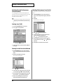
CAUTION
RISK OF ELECTRIC SHOCK
DO NOT OPEN
ATTENTION: RISQUE DE CHOC ELECTRIQUE NE PAS OUVRIR
CAUTION: TO REDUCE THE RISK OF ELECTRIC SHOCK,
DO NOT REMOVE COVER (OR BACK).
NO USER-SERVICEABLE PARTS INSIDE.
REFER SERVICING TO QUALIFIED SERVICE PERSONNEL.
The lightning flash with arrowhead symbol, within an
equilateral triangle, is intended to alert the user to the
presence of uninsulated “dangerous voltage” within the
product’s enclosure that may be of sufficient magnitude to
constitute a risk of electric shock to persons.
The exclamation point within an equilateral triangle is
intended to alert the user to the presence of important
operating and maintenance (servicing) instructions in the
literature accompanying the product.
INSTRUCTIONS PERTAINING TO A RISK OF FIRE, ELECTRIC SHOCK, OR INJURY TO PERSONS.
IMPORTANT SAFETY INSTRUCTIONS
SAVE THESE INSTRUCTIONS
WARNING - When using electric products, basic precautions should always be followed, including the following:
1.
2.
3.
4.
5.
6.
7.
8.
9.
Read these instructions.
Keep these instructions.
Heed all warnings.
Follow all instructions.
Do not use this apparatus near water.
Clean only with a damp cloth.
Do not block any of the ventilation openings. Install in
accordance with the manufacturers instructions.
Do not install near any heat sources such as radiators,
heat registers, stoves, or other apparatus (including
amplifiers) that produce heat.
Do not defeat the safety purpose of the polarized or
grounding-type plug. A polarized plug has two blades with
one wider than the other. A grounding type plug has two
blades and a third grounding prong. The wide blade or the
third prong are provided for your safety. When the provided
plug does not fit into your outlet, consult an electrician for
replacement of the obsolete outlet.
10. Protect the power cord from being walked on or pinched
particularly at plugs, convenience receptacles, and the
point where they exit from the apparatus.
11. Only use attachments/accessories specified by the
manufacturer.
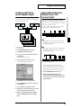
12. Never use with a cart, stand, tripod, bracket,
or table except as specified by the
manufacturer, or sold with the apparatus.
When a cart is used, use caution when
moving the cart/apparatus combination to
avoid injury from tip-over.
13. Unplug this apparatus during lightning storms or when
unused for long periods of time.
14. Refer all servicing to qualified service personnel. Servicing
is required when the apparatus has been damaged in any
way, such as power-supply cord or plug is damaged, liquid
has been spilled or objects have fallen into the apparatus,
the apparatus has been exposed to rain or moisture, does
not operate normally, or has been dropped.
For the U.K.
WARNING:
THIS APPARATUS MUST BE EARTHED
IMPORTANT: THE WIRES IN THIS MAINS LEAD ARE COLOURED IN ACCORDANCE WITH THE FOLLOWING CODE.
GREEN-AND-YELLOW: EARTH, BLUE: NEUTRAL, BROWN: LIVE
As the colours of the wires in the mains lead of this apparatus may not correspond with the coloured markings identifying
the terminals in your plug, proceed as follows:
The wire which is coloured GREEN-AND-YELLOW must be connected to the terminal in the plug which is marked by the
letter E or by the safety earth symbol or coloured GREEN or GREEN-AND-YELLOW.
The wire which is coloured BLUE must be connected to the terminal which is marked with the letter N or coloured BLACK.
The wire which is coloured BROWN must be connected to the terminal which is marked with the letter L or coloured RED.
2
For EU Countries
This product complies with the requirements of European Directives EMC 89/336/EEC and LVD 73/23/EEC.
For the USA
FEDERAL COMMUNICATIONS COMMISSION
RADIO FREQUENCY INTERFERENCE STATEMENT
This equipment has been tested and found to comply with the limits for a Class B digital device, pursuant to Part 15 of the
FCC Rules. These limits are designed to provide reasonable protection against harmful interference in a residential
installation. This equipment generates, uses, and can radiate radio frequency energy and, if not installed and used in
accordance with the instructions, may cause harmful interference to radio communications. However, there is no guarantee
that interference will not occur in a particular installation. If this equipment does cause harmful interference to radio or
television reception, which can be determined by turning the equipment off and on, the user is encouraged to try to correct the
interference by one or more of the following measures:
– Reorient or relocate the receiving antenna.
– Increase the separation between the equipment and receiver.
– Connect the equipment into an outlet on a circuit different from that to which the receiver is connected.
– Consult the dealer or an experienced radio/TV technician for help.
This device complies with Part 15 of the FCC Rules. Operation is subject to the following two conditions:
(1) This device may not cause harmful interference, and
(2) This device must accept any interference received, including interference that may cause undesired operation.
Unauthorized changes or modification to this system can void the users authority to operate this equipment.
This equipment requires shielded interface cables in order to meet FCC class B Limit.
For Canada
NOTICE
This Class B digital apparatus meets all requirements of the Canadian Interference-Causing Equipment Regulations.
AVIS
Cet appareil numérique de la classe B respecte toutes les exigences du Règlement sur le matériel brouilleur du Canada.
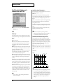
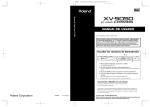
The
symbol alerts the user to important instructions
or warnings.The specific meaning of the symbol is
determined by the design contained within the
triangle. In the case of the symbol at left, it is used for
general cautions, warnings, or alerts to danger.
Used for instructions intended to alert
the user to the risk of death or severe
injury should the unit be used
improperly.
Used for instructions intended to alert
the user to the risk of injury or material
damage should the unit be used
improperly.
* Material damage refers
other adverse effects
respect to the home
furnishings, as well
animals or pets.
The
symbol alerts the user to items that must never
be carried out (are forbidden). The specific thing that
must not be done is indicated by the design contained
within the circle. In the case of the symbol at left, it
means that the unit must never be disassembled.
to damage or
caused with
and all its
to domestic
The ● symbol alerts the user to things that must be
carried out. The specific thing that must be done is
indicated by the design contained within the circle. In
the case of the symbol at left, it means that the powercord plug must be unplugged from the outlet.
001
008e
• Before using this unit, make sure to read the instructions
below, and the Owner’s Manual.
• Use only the attached power-supply cord.
........................................................................................................................
002b
• Do not open or perform any internal modifications on the
unit. (The only exception would be where this manual
provides specific instructions which should be followed in
order to put in place user-installable options; see p. 196.)
........................................................................................................................
003
• Do not attempt to repair the unit, or replace parts within it
(except when this manual provides specific instructions
directing you to do so). Refer all servicing to your retailer,
the nearest Roland Service Center, or an authorized
Roland distributor, as listed on the “Information” page.
........................................................................................................................
004
• Never use or store the unit in places that are:
• Subject to temperature extremes (e.g., direct sunlight
in an enclosed vehicle, near a heating duct, on top of
heat-generating equipment); or are
• Damp (e.g., baths, washrooms, on wet floors); or are
• Humid; or are
• Exposed to rain; or are
• Dusty; or are
• Subject to high levels of vibration.
........................................................................................................................
005
• This unit should be used only with a rack or stand that is
recommended by Roland.
........................................................................................................................
006
• When using the unit with a rack or stand recommended
by Roland, the rack or stand must be carefully placed so it
is level and sure to remain stable. If not using a rack or
stand, you still need to make sure that any location you
choose for placing the unit provides a level surface that
will properly support the unit, and keep it from wobbling.
........................................................................................................................
008a
• The unit should be connected to a power supply only of
the type described in the operating instructions, or as
marked on the unit.
........................................................................................................................
........................................................................................................................
009
• Do not excessively twist or bend the power cord, nor place
heavy objects on it. Doing so can damage the cord,
producing severed elements and short circuits. Damaged
cords are fire and shock hazards!
........................................................................................................................
010
• This unit, either alone or in combination with an amplifier
and headphones or speakers, may be capable of
producing sound levels that could cause permanent
hearing loss. Do not operate for a long period of time at a
high volume level, or at a level that is uncomfortable. If
you experience any hearing loss or ringing in the ears, you
should immediately stop using the unit, and consult an
audiologist.
........................................................................................................................
011
• Do not allow any objects (e.g., flammable material, coins,
pins); or liquids of any kind (water, soft drinks, etc.) to
penetrate the unit.
........................................................................................................................
013
• In households with small children, an adult should
provide supervision until the child is capable of following
all the rules essential for the safe operation of the unit.
........................................................................................................................
014
• Protect the unit from strong impact.
(Do not drop it!)
........................................................................................................................
015
• Do not force the unit’s power-supply cord to share an
outlet with an unreasonable number of other devices. Be
especially careful when using extension cords—the total
power used by all devices you have connected to the
extension cord’s outlet must never exceed the power
rating (watts/amperes) for the extension cord. Excessive
loads can cause the insulation on the cord to heat up and
eventually melt through.
........................................................................................................................
3
USING THE UNIT SAFELY
016
106
• Before using the unit in a foreign country, consult with
your retailer, the nearest Roland Service Center, or an
authorized Roland distributor, as listed on the “Information” page.
........................................................................................................................
• Never climb on top of, nor place heavy objects on the unit.
022a
• Always turn the unit off and unplug the power cord
before attempting installation of the circuit board (SRJV80/SRX Series; Quick Start p. 3–4).
........................................................................................................................
........................................................................................................................
107b
• Never handle the power cord or its plugs with wet hands
when plugging into, or unplugging from, an outlet or this
unit.
........................................................................................................................
108a
• Before moving the unit, disconnect the power plug from
the outlet, and pull out all cords from external devices.
........................................................................................................................
109a
101a
• The unit should be located so that its location or position
does not interfere with its proper ventilation.
........................................................................................................................
• Before cleaning the unit, turn off the power and unplug
the power cord from the outlet (Quick Start p. 5).
........................................................................................................................
101c
110a
• This unit for use only with Roland keyboard stand KS-12.
Use with other stands is capable of resulting in instability
causing possible injury.
........................................................................................................................
• Whenever you suspect the possibility of lightning in your
area, pull the plug on the power cord out of the outlet.
102b
115a
• Install only the specified circuit board(s) (SR-JV80/SRX
Series). Remove only the specified screws (p. 196, p. 198).
• Always grasp only the plug on the power-supply cord
when plugging into, or unplugging from, an outlet or this
unit.
........................................................................................................................
104
• Try to prevent cords and cables from becoming entangled.
Also, all cords and cables should be placed so they are out
of the reach of children.
........................................................................................................................
........................................................................................................................
........................................................................................................................
118
• Should you remove screws, make sure to put them in a
safe place out of children’s reach, so there is no chance of
them being swallowed accidentally.
........................................................................................................................
IMPORTANT NOTES
In addition to the items listed under “IMPORTANT SAFETY INSTRUCTIONS” and “USING THE UNIT SAFELY” on pages 2 and 3, please
read and observe the following:
Power Supply
301
• Do not use this unit on the same power circuit with any device
that will generate line noise (such as an electric motor or variable
lighting system).
307
• Before connecting this unit to other devices, turn off the power to
all units. This will help prevent malfunctions and/or damage to
speakers or other devices.
Placement
351
• Using the unit near power amplifiers (or other equipment
containing large power transformers) may induce hum. To
alleviate the problem, change the orientation of this unit; or move
it farther away from the source of interference.
352
• This device may interfere with radio and television reception. Do
not use this device in the vicinity of such receivers.
4
353
• Observe the following when using the unit’s floppy disk drive.
For further details, refer to “Before Using Floppy Disks.”
• Do not place the unit near devices that produce a strong
magnetic field (e.g., loudspeakers).
• Install the unit on a solid, level surface.
• Do not move the unit or subject it to vibration while the drive
is operating.
354a
• Do not expose the unit to direct sunlight, place it near devices that
radiate heat, leave it inside an enclosed vehicle, or otherwise
subject it to temperature extremes. Excessive heat can deform or
discolor the unit.
355
• To avoid possible breakdown, do not use the unit in a wet area,
such as an area exposed to rain or other moisture.
358
• Do not allow objects to remain on top of the keyboard. This can be
the cause of malfunction, such as keys ceasing to produce sound.
IMPORTANT NOTES
Maintenance
401a
• For everyday cleaning wipe the unit with a soft, dry cloth or one
that has been slightly dampened with water. To remove stubborn
dirt, use a cloth impregnated with a mild, non-abrasive detergent.
Afterwards, be sure to wipe the unit thoroughly with a soft, dry
cloth.
402
• Never use benzine, thinners, alcohol or solvents of any kind, to
avoid the possibility of discoloration and/or deformation.
604
• To insert a disk, push it gently but firmly into the drive—it will
click into place. To remove a disk, press the EJECT button firmly.
Do not use excessive force to remove a disk which is lodged in the
drive.
605a
• Never attempt to remove a floppy disk from the drive while the
drive is operating (the indicator is lit); damage could result to both
the disk and the drive.
606
• Remove any disk from the drive before powering up or down.
607
Additional Precautions
551
• Please be aware that the contents of memory can be irretrievably
lost as a result of a malfunction, or the improper operation of the
unit. To protect yourself against the risk of loosing important data,
we recommend that you periodically save a backup copy of
important data you have stored in the unit’s memory on a floppy
disk.
• To prevent damage to the disk drive’s heads, always try to hold
the floppy disk in a level position (not tilted in any direction)
while inserting it into the drive. Push it in firmly, but gently.
Never use excessive force.
608
• To avoid the risk of malfunction and/or damage, insert only
floppy disks into the disk drive. Never insert any other type of
disk. Avoid getting paper clips, coins, or any other foreign objects
inside the drive.
552
• Unfortunately, it may be impossible to restore the contents of data
that was stored on a floppy disk, in the unit’s memory or another
MIDI device (e.g., a sequencer) once it has been lost. Roland
Corporation assumes no liability concerning such loss of data.
553
• Use a reasonable amount of care when using the unit’s buttons,
sliders, or other controls; and when using its jacks and connectors.
Rough handling can lead to malfunctions.
554
• Never strike or apply strong pressure to the display.
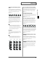
Handling Floppy Disks
651
• Floppy disks contain a plastic disk with a thin coating of magnetic
storage medium. Microscopic precision is required to enable
storage of large amounts of data on such a small surface area. To
preserve their integrity, please observe the following when
handling floppy disks:
• Never touch the magnetic medium inside the disk.
• Do not use or store floppy disks in dirty or dusty areas.
556
• When connecting / disconnecting all cables, grasp the connector
itself—never pull on the cable. This way you will avoid causing
shorts, or damage to the cable’s internal elements.
557
• Do not subject floppy disks to temperature extremes (e.g.,
direct sunlight in an enclosed vehicle). Recommended temperature range: 10 to 50° C (50 to 122° F).
• A small amount of heat will radiate from the unit during normal
operation.
• Do not expose floppy disks to strong magnetic fields, such as
those generated by loudspeakers.
558a
• To avoid disturbing your neighbors, try to keep the unit’s volume
at reasonable levels. You may prefer to use headphones, so you do
not need to be concerned about those around you (especially
when it is late at night).
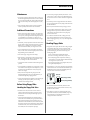
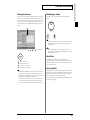
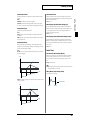
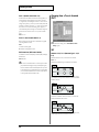
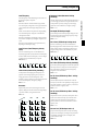
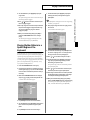
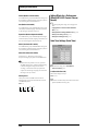
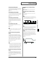
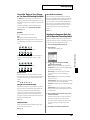
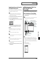
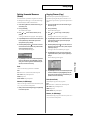
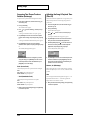
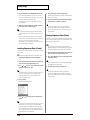
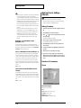
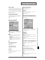
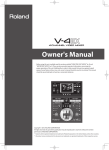
652
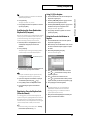
• Floppy disks have a “write protect” tab which can protect the disk
from accidental erasure. It is recommended that the tab be kept in
the PROTECT position, and moved to the WRITE position only
when you wish to write new data onto the disk.
559a
• When you need to transport the unit, package it in the box
(including padding) that it came in, if possible. Otherwise, you
will need to use equivalent packaging materials.
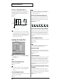
Protect tab
561
Write (writing permitted)
• Use only the specified expression pedal (EV-5; sold separately). By
connecting any other expression pedals, you risk causing
malfunction and/or damage to the unit.
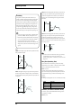
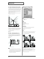
Before Using Floppy Disks
Handling the Floppy Disk Drive
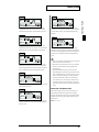
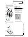
602
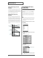
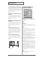
• Install the unit on a solid, level surface in an area free from
vibration. If the unit must be installed at an angle, be sure the
installation does not exceed the permissible range: upward, 2°;
downward, 18°.
603
Protect (writing prohibited)
653
• The identification label should be firmly affixed to the disk.
Should the label come loose while the disk is in the drive, it may
be difficult to remove the disk.
654
• Store all disks in a safe place to avoid damaging them, and to
protect them from dust, dirt, and other hazards. By using a dirty
or dust-ridden disk, you risk damaging the disk, as well as
causing the disk drive to malfunction.
• Avoid using the unit immediately after it has been moved to a
location with a level of humidity that is greatly different than its
former location. Rapid changes in the environment can cause
condensation to form inside the drive, which will adversely affect
the operation of the drive and/or damage floppy disks. When the
unit has been moved, allow it to become accustomed to the new
environment (allow a few hours) before operating it.
5
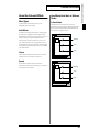
How To Use This Manual
This owner’s manual is organized as follows. Before you start
reading it, we’d like to suggest going through the Quick Start
manual. For parameter lists, sound lists, and MIDI implementation,
refer to the separate “Sound/Parameter List.” In addition, the
separate “Q&A” provides answers for frequently asked questions
about the Fantom, and example applications for your reference.
Recording a Song
Overview of the Fantom
This chapter explains song editing and song settings in detail. Read
this when you wish to edit a song that you’ve recorded.
This explains the structure of the Fantom, and basic operation.
Reading it is essential for understanding Fantom operational
procedures.
Playing in Patch Mode
This explains how to record a song using the Fantom’s sequencer.
Reading it is essential for understanding Fantom operational
procedures.
Editing a Song
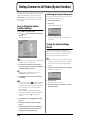
Playing Phrase with One Finger
(RPS Function)
This explains how to play the Fantom in Patch mode. Reading it is
essential for understanding Fantom operational procedures.
This explains the settings of the RPS (Realtime Phrase Sequence)
function, and how to use it for performance. Read this chapter when
you wish to use the RPS.
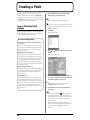
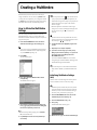
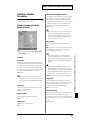
Creating a Patch
Changing Tones in Realtime
This chapter explains how to create patches, and describes what the
patch parameters do and how they are composed. Read this chapter
when you wish to create patches.
This explains how to use the D Beam controller and realtime
controllers to modify the sound, and how to make the necessary
settings. Read this when you want to modify the sound in realtime.
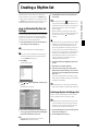
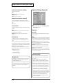
Creating a Rhythm Set
Applying Effects
This chapter explains how to create rhythm sets, and describes what
the rhythm set parameters do and how they are composed. Read this
chapter when you wish to create rhythm sets.
This chapter explains how to make settings for the Fantom’s onboard
effects, and describes the type and operation of each effect. Be sure to
read this when adding effects to patches and performances.
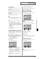
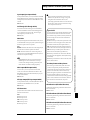
Playing in Performance Mode
Settings Common to All Modes
(System Function)
This explains how to play the Fantom in Performance mode.
Reading it is essential for understanding Fantom operational
procedures.
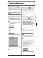
Creating a Performance
This chapter explains how to create performances, and describes
what the performance parameters do and how they are composed.
Read this chapter when you wish to create performances.
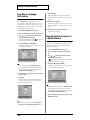
Playing in Multitimbre Mode
This explains how to play the Fantom in Multitimbre mode. Reading
it is essential for understanding Fantom operational procedures.
Creating a Multitimbre
This explains how to create a multitimbre, and the functions and
structure of the multitimbre parameters. Read this when you wish to
create a multitimbre.
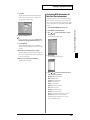
Playing Back a Song
This explains how to play back a song using the Fantom’s sequencer.
Reading it is essential for understanding Fantom operational
procedures.
6
This chapter describes how the System parameters that determine
the Fantom’s operation environment work and how these
parameters are organized. Read it as necessary.
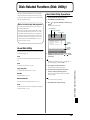
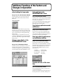
Disk-Related Functions (Disk Utility)
This chapter covers disk-related operations such as saving data to
disk and loading data from disk. Read it as necessary.
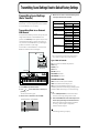
Transmitting Sound Settings/
Restoring the Factory Settings
This explains how to transmit data to an external MIDI device or to
the Fantom (Data Transfer), and how to restore all data of the
Fantom to the factory settings (Factory Reset). Read it as necessary.
Installing the Wave Expansion Board
This explains how to install a Wave Expansion Board (sold
separately). Read it as necessary.
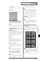
How To Use This Manual
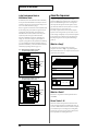
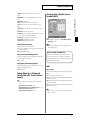
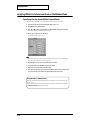
Notation Used in This Owner’s
Manual
To make operation procedures easy to understand, the following
notation system is adopted:
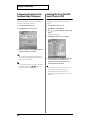
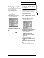
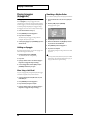
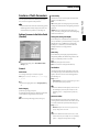
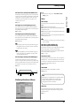
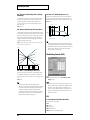
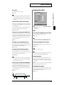
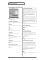
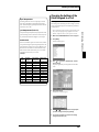
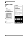
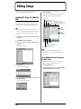
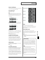
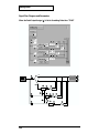
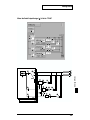
The display screens printed in this owner’s manual are based on
the factory settings. However, please be aware that in some cases
they may differ from the actual factory settings.
Characters and numbers in square brackets [ ] indicate buttons and
knobs on the front panel. For example, [MODE] indicates the MODE
button, and [CURSOR] indicates the cursor buttons
(
,
, , ).
(p. **) refers to pages within the manual.
In this manual, when any particular parameter is referred to, the
name of the parameter is given, and this is then followed (in
parenthesis) by information detailing its mode/edit group. For
example: Mono/Poly parameter (PATCH/General).
Below are the meanings of the symbols preceding certain sentences
in the text.
These are notes. Be sure to read them.
These are reference memos. Read it as necessary.
These are hints for operating the Fantom. Read it as necessary.
These provide information from related reference pages. Read it
as necessary.
7
Contents
IMPORTANT NOTES ...............................................................................4
How To Use This Manual........................................................................6
Notation Used in This Owner’s Manual...................................................................................... 7
Main Features........................................................................................14
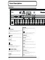
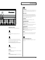
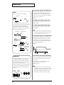
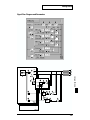
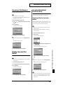
Panel Descriptions................................................................................16
Front Panel................................................................................................................................................. 16
Rear Panel .................................................................................................................................................. 18
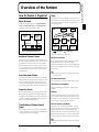
Overview of the Fantom .......................................................................19
How the Fantom Is Organized ............................................................................................................... 19
Basic Structure ............................................................................................................................... 19
Classification of Fantom Sound Types....................................................................................... 19
About Simultaneous Polyphony................................................................................................. 21
About Memory.......................................................................................................................................... 22
Temporary Memory...................................................................................................................... 22
Rewritable Memory ...................................................................................................................... 22
Non-Rewritable Memory ............................................................................................................. 22
About the Onboard Effects ..................................................................................................................... 23
Effect Types.................................................................................................................................... 23
How Effects Units Work in Different Modes ............................................................................ 23
About the Sequencer ................................................................................................................................ 24
What Is a Song? ............................................................................................................................. 24
What Is a Track? ............................................................................................................................ 24
Songs and the Sound Generator Mode ...................................................................................... 25
How Phrase Tracks, Parts and MIDI Channels Interact.......................................................... 25
Positions for Storing a Song......................................................................................................... 26
Basic Operation of the Fantom ............................................................................................................... 27
Switching the Sound Generator Mode ([MODE]) .................................................................... 27
Switching Screens from the Menu ([MENU]) ........................................................................... 28
Viewing a List of Patches or Other Data ([LIST]) ..................................................................... 28
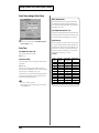
About the [1]–[8] Buttons............................................................................................................. 28
Moving the Cursor........................................................................................................................ 29
Modifying a Value ........................................................................................................................ 29
Assigning a Name ......................................................................................................................... 30
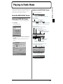
Playing in Patch Mode..........................................................................31
About the PATCH PLAY Screen............................................................................................................ 31
Displaying PATCH PLAY Screen............................................................................................... 31
Selecting a Patch ....................................................................................................................................... 32
Selecting Favorite Patches (Favorite Sound) ............................................................................. 33
Selecting Patches from the List.................................................................................................... 33
Auditioning Patches (Phrase Preview) ...................................................................................... 34
Selecting Patches by Category (Patch Finder) .......................................................................... 34
Transposing the Keyboard in Octave Units (Octave Shift) ................................................................ 35
Transposing the Keyboard in Semitone Steps (Transpose)................................................................ 36
Selecting the Tones That Will Sound (Tone On/Off).......................................................................... 36
Playing Single Notes (Mono) .................................................................................................................. 37
Creating Smooth Pitch Changes (Portamento) .................................................................................... 37
Playing Arpeggios (Arpeggiator)........................................................................................................... 38
Holding an Arpeggio.................................................................................................................... 38
Simulating a Rhythm Guitar ....................................................................................................... 38
Using an External MIDI Keyboard to Play Arpeggios ............................................................ 39
Making Arpeggiator Settings ...................................................................................................... 39
8
Contents
Playing Percussion Instruments............................................................................................................. 40
Selecting a Rhythm Set ................................................................................................................. 40
Playing a Rhythm Set ................................................................................................................... 41
Playing Rhythm Patterns from the Keyboard...................................................................................... 41
Holding the Playback of a Rhythm Pattern .............................................................................. 41
Making Rhythm Pattern Settings................................................................................................ 41
Creating a Patch....................................................................................42
How to Make the Patch Settings ............................................................................................................ 42
Initializing Patch Settings (Init)................................................................................................... 43
Copying Patch Settings (Copy) ................................................................................................... 43
Cautions When Selecting a Waveform ...................................................................................... 44
Saving Patches You’ve Created (Write) ................................................................................................ 45
Auditioning the Save-Destination Patch (Compare) ............................................................... 46
Registering a Favorite Patch (Favorite Sound) ......................................................................... 46
Functions of Patch Parameters ............................................................................................................... 47
Settings Common to the Entire Patch (General)....................................................................... 47
Arpeggiator Settings (Arpeggio) ................................................................................................ 51
Realtime Controller / D Beam Controller Settings (Controller) ............................................ 52
Setting Effects for a Patch (Effects/MFX/MFX Control/Chorus/Reverb) .......................... 53
Matrix Control Settings (Matrix Ctrl)......................................................................................... 54
Changing How a Tone Is Sounded (TMT) ................................................................................ 56
Modifying Waveforms (Wave) ................................................................................................... 59
Modifying Pitch (Pitch) ................................................................................................................ 60
Modifying the Brightness of a Sound with a Filter (TVF)....................................................... 62
Adjusting the Volume (TVA) ...................................................................................................... 64
Modulating Sounds (LFO) ........................................................................................................... 66
Creating a Rhythm Set .........................................................................69
How to Make the Rhythm Set Settings ................................................................................................. 69
Initializing Rhythm Set Settings (Init)........................................................................................ 69
Copying Rhythm Set Settings (Copy) ........................................................................................ 70
Cautions When Selecting a Waveform ...................................................................................... 71
Saving Rhythm Sets You’ve Created (Write) ....................................................................................... 72
Auditioning the Save-Destination Rhythm Set (Compare) .................................................... 73
Registering Favorite Rhythm Sets (Favorite Sound)................................................................ 73
Functions of Rhythm Set Parameters .................................................................................................... 74
Settings Common to the Entire Rhythm Set (General) ............................................................ 74
Rhythm Pattern Settings (Rhythm Ptn) ..................................................................................... 75
Realtime Controller / D Beam Controller Settings (Controller) ............................................ 76
Setting Effects for a Rhythm Set (Effects/MFX/MFX Control/Chorus/Reverb) ............... 77
Changing How a Rhythm Tone Is Sounded (WMT) ............................................................... 77
Modifying Pitch (Pitch) ................................................................................................................ 79
Modifying the Brightness of a Sound with a Filter (TVF)....................................................... 80
Adjusting the Volume (TVA) ...................................................................................................... 82
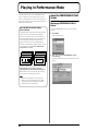
Playing in Performance Mode..............................................................84
About the PERFORMANCE PLAY Screen........................................................................................... 84
Displaying PERFORMANCE PLAY Screen.............................................................................. 84
Selecting a Performance........................................................................................................................... 85
Selecting Favorite Performances (Favorite Sound) .................................................................. 86
Selecting Performances from the List......................................................................................... 86
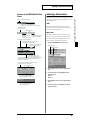
Combining and Playing Sounds Together (Layer).............................................................................. 87
Playing Different Sounds in Different Areas of the Keyboard (Split) .............................................. 87
Playing Arpeggios in a Specific Region of the Keyboard................................................................... 88
Playing Rhythm Patterns in a Specific Region of the Keyboard ....................................................... 89
9
Contents
Using the Fantom As a Master Keyboard............................................................................................. 90
Changing the Connections between Keyboard and Sound Generator (Zone) .................... 90
Confirming MIDI Information for Each Part (Part Information) ...................................................... 90
Creating a Performance .......................................................................91
How to Make the Performance Settings................................................................................................ 91
Initializing Performance Settings (Init)...................................................................................... 91
Copying Performance Settings (Copy) ...................................................................................... 92
Saving Performance You’ve Created (Write) ....................................................................................... 93
Registering a Favorite Performance (Favorite Sound) ............................................................ 93
Functions of Performance Parameters................................................................................................... 94
Settings Common to the Entire Performance (General) .......................................................... 94
Arpeggiator Settings (Arpeggio) ................................................................................................ 95
Rhythm Pattern Settings (Rhythm Ptn) ..................................................................................... 96
Realtime Controller / D Beam Controller Settings (Controller) ............................................ 97
Zone Settings (Zone)..................................................................................................................... 98
Making Settings for Each Part (Part) ........................................................................................ 100
Making Settings for Receiving MIDI (MIDI)........................................................................... 103
Setting Effects for a Performance (Effects/MFX/MFX Control/Chorus/Reverb) ........... 104
Scale Tune Settings (Scale Tune)............................................................................................... 104
Changing the Settings of the Patch Assigned to a Part..................................................................... 105
Playing in Multitimbre Mode ..............................................................106
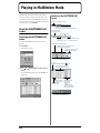
About the MULTITIMBRE PLAY screen ............................................................................................ 106
Displaying the MULTITIMBRE PLAY screen ........................................................................ 106
Selecting a Multitimbre.......................................................................................................................... 107
Selecting Multitimbres from a List ........................................................................................... 107
Playing Back a Song ............................................................................................................................... 108
Selecting a Part to Play from the Keyboard (Current Part) .............................................................. 108
Selecting a Part to Play Individually (Solo) ........................................................................................ 108
Silencing the Playback of a Specific Part (Mute)................................................................................ 109
Assigning a Different Patch to a Part .................................................................................................. 109
Adjusting the Volume and Pan of Each Part...................................................................................... 109
Recording an Arpeggio Performance .................................................................................................. 110
Recording the Performance of a Rhythm Pattern.............................................................................. 110
Confirming MIDI Information for Each Part (Part Information) ......................................... 111
Creating a Multitimbre ........................................................................112
How to Make the Multitimbre Settings............................................................................................... 112
Initializing Multitimbre Settings (Init) ..................................................................................... 112
Copying Multitimbre Settings (Copy) ..................................................................................... 113
Saving Multitimbre You’ve Created (Write) ...................................................................................... 114
Functions of Multitimbre Parameters.................................................................................................. 115
Settings Common to the Entire Multitimbre (General) ......................................................... 115
Making Settings for Each Part (Part) ........................................................................................ 115
Making Settings for Receiving MIDI (MIDI)........................................................................... 118
Setting Effects for a Multitimbre (Effects/MFX/MFX Control/Chorus/Reverb) ............ 120
Scale Tune Settings (Scale Tune)............................................................................................... 120
Changing the Settings of the Patch Assigned to a Part..................................................................... 121
10
Contents
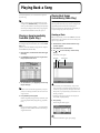
Playing Back a Song...........................................................................122
Playing a Song Immediately from Disk (Quick Play) ....................................................................... 122
Playing Back Songs Consecutively (Chain Play) ............................................................................... 122
Creating a Chain.......................................................................................................................... 122
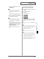
Saving a Chain to Disk (Save) ................................................................................................... 123
Loading a Chain from Disk (Load)........................................................................................... 124
Playing a Chain ........................................................................................................................... 124
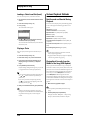
Various Playback Methods ................................................................................................................... 124
Fast-Forward and Rewind During Playback .......................................................................... 124
Playing Back Correctly from the Middle of the Song (MIDI Update)................................. 124
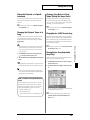
Muting the Playback of a Specific Instrument ........................................................................ 125
Changing the Playback Tempo of a Song................................................................................ 125
Playing a Song Back at a Fixed Tempo (Muting the Tempo Track) .................................... 125
Playing Back a S-MRC Format Song ........................................................................................ 125
Playing Back a Song Repeatedly (Loop Play) ......................................................................... 125
Using the D Beam Controller to Start/Stop Song Playback ................................................. 126
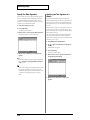
Recording Songs ................................................................................127
Two Recording Methods............................................................................................................ 127
Before You Record a New Song ........................................................................................................... 127
Select the Sound to be Used for Recording ............................................................................. 127
Erasing the Song from Internal Memory (Song Initialize) .................................................... 127
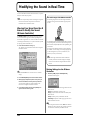
Specify the Time Signature ........................................................................................................ 128
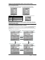
Recording Your Performance as You Play It (Realtime Recording) ............................................... 129
Basic Operation for Realtime Recording ................................................................................. 129
Recording Tempo Changes in a Song (Tempo Recording)................................................... 130
Loop Recording and Punch-In Recording............................................................................... 130
Correct the Timing of Your Playing as You Record (Recording Quantize) ....................... 131
Selecting the Sequencer Data that will Be Recorded (Recording Select) ............................ 131
Erasing Unwanted Data While You Record (Realtime Erase).............................................. 132
Auditioning Sounds or Phrases While Recording (Rehearsal Function)............................ 132
Inputting Data One Step at a Time (Step Recording)........................................................................ 132
Inputting Notes and Rests ......................................................................................................... 132
Assigning a Pattern to a Phrase Track ..................................................................................... 134
Saving a Recorded Song on Disk ......................................................................................................... 135
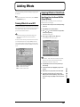
Editing Songs......................................................................................136
Loading the Song You Want to Edit .................................................................................................... 136
Using Different Sound Generators for Each Track ................................................................ 136
Silencing the Playback of a Track (Mute) ................................................................................ 137
Overall Settings for the Song ................................................................................................................ 137
Assigning a Name to a Song (Song Name) ............................................................................. 137
Assigning a Name to a Pattern (Pattern Name) ..................................................................... 138
Assigning Markers (Locate Positions) to a Song .................................................................... 138
Specifying the Area of a Song that will Repeat (Loop Points).............................................. 139
Editing Sequencer Data Over the Specified Range (Track Edit) ..................................................... 139
Basic Operation for Track Editing ............................................................................................ 139
Aligning a Song’s Timing (Quantize) ...................................................................................... 140
Erasing Unwanted Performance Data (Erase) ........................................................................ 142
Deleting Unwanted Measures (Delete).................................................................................... 143
Copying Phrases (Copy) ............................................................................................................ 143
Inserting a Blank Measure (Insert Measure) ........................................................................... 145
Transpose the Key (Transpose)................................................................................................. 145
Changing the Velocity (Volume) (Change Velocity) ............................................................. 146
Changing the MIDI Channel (Change Channel) .................................................................... 147
Modifying the Length of Notes (Change Gate Time) ............................................................ 147
Combining Two Phrase Tracks or Patterns into One (Merge) ............................................. 148
11
Contents
Extracting and Moving a Part of Sequencer Data (Extract) .................................................. 149
Shifting Performance Data Forward and Back (Shift Clock) ................................................ 150
Thinning Out the Sequencer Data (Data Thin) ....................................................................... 151
Swapping Two Phrase Tracks or Patterns (Exchange) .......................................................... 152
Adjusting the Song’s Playback Time (Time Fit) ..................................................................... 152
Deleting Blank Measures (Truncate) ........................................................................................ 153
Editing Individual Items of Sequencer Data (Micro Edit)................................................................ 153
Viewing Sequencer Data (in the Microscope Window) ........................................................ 153
Sequencer Data Handled by a Phrase Track/Pattern............................................................ 154
Viewing sequencer data (View) ................................................................................................ 155
Editing the Sequencer Data ....................................................................................................... 155
Inserting Sequencer Data (Create) ............................................................................................ 156
Erasing Sequencer Data (Erase) ................................................................................................ 156
Moving Sequencer Data (Move) ............................................................................................... 157
Copying Sequencer Data (Copy) .............................................................................................. 157
Changing the Tempo Midway Through the Song ................................................................. 158
Changing the Time Signature Midway Through the Song................................................... 158
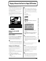
Playing a Phrase at the Touch of a Finger (RPS Function) ............159
Before You Use the RPS Function ........................................................................................................ 159
Record a Pattern .......................................................................................................................... 159
Settings for the RPS Function .................................................................................................... 159
Using the RPS Function While You Perform...................................................................................... 160
Performing with the RPS Function from an External MIDI Keyboard ............................... 161
Recording a Performance Using the RPS Function................................................................ 161
Modifying the Sound in Real Time ....................................................162
Waving Your Hand Over the D Beam to Modify the Sound (D Beam Controller) ...................... 162
Making Settings for the D Beam Controller ............................................................................ 162
Using Knobs or Buttons to Modify the Sound (Realtime Controller) ............................................ 163
Making Realtime Controller Settings ....................................................................................... 163
Using a Pedal to Modify the Sound (Control Pedal)......................................................................... 164
Making Control Pedal Settings ................................................................................................. 164
Adding Effects.....................................................................................165
Turning Effects On and Off................................................................................................................... 165
Applying Effects in Patch Mode .......................................................................................................... 165
Specifying How the Sound Will Be Output (Effects)............................................................. 165
Signal Flow Diagram and Parameters ..................................................................................... 166
Applying Effects in Performance Mode or Multitimbre Mode ....................................................... 170
Specifying How the Sound Will Be Output (Effects)............................................................. 170
Signal Flow Diagram and Parameters ..................................................................................... 171
Making Multi-Effects Settings (MFX/MFX Control) ........................................................................ 174
Setting Procedure ........................................................................................................................ 174
Functions of Parameters............................................................................................................. 175
Making Chorus Settings (Chorus) ....................................................................................................... 176
Setting Procedure ........................................................................................................................ 176
Functions of Parameters............................................................................................................. 176
Making Reverb Settings (Reverb) ........................................................................................................ 177
Setting Procedure ........................................................................................................................ 177
Functions of Parameters............................................................................................................. 177
12
Contents
Settings Common to All Modes (System Function) ........................178
How to Make the System Function Settings....................................................................................... 178
Initializing the System Settings (Init) ....................................................................................... 178
Saving the System Settings (Write) ...................................................................................................... 178
Functions of System Parameters .......................................................................................................... 179
Settings Common to the Entire System (General).................................................................. 179
Sequencer Settings (Sequencer)................................................................................................. 180
MIDI Settings (MIDI).................................................................................................................. 182
Controller Settings (Controller) ................................................................................................ 184
Equalizer settings (EQ)............................................................................................................... 185
Phrase Preview Settings (Preview)........................................................................................... 185
Scale Tune settings (Scale Tune) ............................................................................................... 186
Disk-Related Functions (Disk Utility) ................................................187
About Disk Utility .................................................................................................................................. 187
Basic Disk Utility Operations................................................................................................................ 187
Selecting the Type of Files Displayed in the File List (View)........................................................... 188
Loading a File from Disk into the Fantom (Load) ............................................................................. 188
Loading Individual Tracks/Patterns of Song Data................................................................ 188
Loading Individual Items of Sound Data ................................................................................ 189
Saving Data on Disk (Save)................................................................................................................... 189
Copying a File to Another Name (Copy)............................................................................................ 190
Renaming a File (Rename) .................................................................................................................... 191
Deleting Unwanted Files (Delete) ........................................................................................................ 191
Executing Disk-Related Functions (Tools).......................................................................................... 191
Preparing a Disk for Use by the Fantom ................................................................................. 191
Modifying the Name of the Disk .............................................................................................. 192
Checking Files Recorded on Disk ............................................................................................. 192
Creating a Duplicate Disk.......................................................................................................... 193
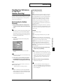
Transmitting Sound Settings/Reset to Default Factory Settings ...194
Transmitting Sound Settings (Data Transfer) .................................................................................... 194
Transmitting Data to an External MIDI Device...................................................................... 194
Transmitting Data to User Memory ......................................................................................... 195
Reset to Default Factory Settings (Factory Reset) .............................................................................. 195
Installing the Wave Expansion Board...............................................196
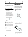
Cautions When Installing an Wave Expansion Board ...................................................................... 196
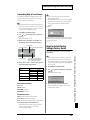
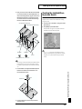
How to Install a Wave Expansion Board ............................................................................................ 196
Checking the Installed Wave Expansion Boards ............................................................................... 197
Installation de la carte d’expansion Wave
(French language for Canadian Safety Standard) ...........................198
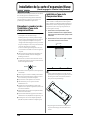
Précautions à prendre lors de l’installation d’une carte d’expansion Wave ................................. 198
Installation d’une carte d’expansion Wave ........................................................................................ 198
Vérification des cartes d’extension audio aprés installation............................................................ 199
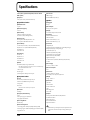
Specifications......................................................................................200
13
Main Features
● A synthesizer with the operability
and playability of a musical
instrument
The category of synthesizers known as “workstations”—consisting
of a sound generator section that creates the sound, a controller
section, and a sequencer section to produce music—has taken its
own evolutionary path, adding various new functionality that opens
up new possibilities of musical expression and creation. On the other
hand, access to such functionality has generally been provided
through a restrictive, complex interface, which has all too often
hampered the creativity of the musician.
The Fantom not only features superb operability for performance,
but also is comprehensively designed to support the musician’s
creativity in every area, including composition. It lets you work
seamlessly through every aspect of the music production process,
from performance to composition, allowing you to hold onto your
inspiration.
● Consolidated interface design with
large graphic LCD
● Power effects including COSM
effects
The effects indispensable for synthesizer sound creation are
provided—in studio quality.
For reverb, a DSP equivalent to SRV-3030 quality is built-in,
delivering clear reverb with smooth decays.
The total of 90 types of multi-effects (M-FX) include not only effects
such as RSS, 3D delay, and slicer, but also effects that use Roland’s
proprietary COSM modeling technology, such as guitar amp
simulations, guitar multi’s, bass multi’s, and keyboard multi’s.
In Multitimbre mode and Performance mode, three types of M-FX
can be used simultaneously, letting you use different M-FX effects on
a desired part. What’s more, a two-band EQ is provided for each
output jack.
● Comprehensive music production
with a superior performance
sequencer based on the MRC-Pro
The Fantom features a large quarter-VGA sized LCD. The graphical
display uses four levels of grayscale to simultaneously show all
relevant settings for sounds or sequencer operations, guaranteeing
smooth operation.
The Fantom contains a 16-track sequencer based on the MRC-Pro
sequencer, delivering high resolution that captures every expressive
detail of your performance, and providing speedy data entry and
editing for both realtime and step recording. In conjunction with the
power sound generator, the Fantom is a serious music production
environment in a single package.
Since a large amount of data can be displayed at once, buttons and
knobs are laid out simply, letting you access a desired parameter
with a minimum of operation. The interface is designed with your
creativity as the first priority.
In addition, the Fantom lets you start recording immediately from
any mode (whether you are editing sounds or performing), simply
by pressing the [REC] button. You can record your improvisations in
real time, and create songs based on your captured inspirations.
● Top-level sound generator for
maximum expressive power
It goes without saying that you can use Micro editing to edit your
recorded data in every detail. Since the large display lets you view 16
tracks of recorded data at once, editing can be performed faster,
more efficiently, and in greater detail than on previous workstations.
The Fantom contains the same type of 64-voice/16-part multitimbral
sound generator as on the XV-5080, acclaimed by music production
professionals. The total of 896 preset patches include new patches
that have been tuned specifically for the Fantom to take advantage of
its keyboard, knobs, and other realtime controllers.
Four-level velocity switching lets you move between four stereo
waves, for the same amazing expressive power as on the XV-5080.
The spaciousness of the sound field, tonal changes controlled by
velocity, and endless details of expressive nuance are at your
fingertips. Matrix Control lets you vary large numbers of parameters
at once, and can be controlled using realtime controllers such as the
knobs and D Beam control. The Fantom’s dynamic expressive power
can be controlled by simple operations.
Wave Expansions Boards can also be installed to freely customize
your Fantom for your favorite musical styles or applications. Two
slots for the SRX series expansion boards allow the addition of highquality sounds using a maximum of 64 M bytes of high-quality wave
memory, and another slot lets you install one of the wide selection of
SR-JV80 series expansion boards.
In addition to four parallel outputs, which can be used as two stereo
pairs, S/P DIF digital out (both optical and coaxial) is also provided.
The Fantom is a great match for any digital recording system.
14
Sequencer data can be saved and loaded in the native MRC format
or as SMF. The built-in floppy disk drive makes it easy to exchange
data with another sequencer or computer.
The Fantom boasts a new Multitimbre mode. By displaying 16 parts
simultaneously, this lets you quickly create orchestrations, and
makes song arrangements simple and intuitive.
Main Features
● Functions that stimulate your
creativity
● General MIDI- and General MIDI 2Compatible
The Fantom provides numerous functions that enhance its
playability for realtime performance, and let you develop this into
musical productions.
The Fantom is compatible with both General MIDI and General
MIDI 2 standards. Any General MIDI and/or General MIDI 2
compatible music data (GM score) can be played back on the
Fantom.
Numerous drum patterns based in actual professional drum playing
are built in. Twelve types of pattern variations including fills are
assigned to an octave of the keyboard, allowing you to perform the
drum part in real time. In addition, the drums can be made to play at
a steady, natural tempo, regardless of the timing at which you press
the keys.
A newly developed arpeggiator is also built-in. In addition to
complex phrases that would be impossible to play by hand, you can
also use the arpeggiator to play phrases that are similar to actual
performance. Furthermore, the D Beam and other realtime
controllers can be used to modify the arpeggio style. This not only
makes for a dramatic leap in expressive potential during a live
performance, but also supports your own playing.
Phrases played by rhythm patterns or the arpeggiator can be
recorded on the sequencer just as they are played. Your realtime
performance can be saved instantly as song data, or even used as a
template for a step-recorded phrase.
In addition, patterns created on the sequencer can be triggered by
the keyboard and played by the RPS (Realtime Phrase Sequence)
function. Rhythm patterns and complex phrases created using the
arpeggiator can be recorded on the sequencer, and then played in
real time, for amazing live performance possibilities.
● Designed to be a true musical
instrument
In a departure from the straight-line design of previous
workstations, the Fantom features a distinctive design, which
proclaims its worthiness as a true musical instrument, while at the
same time projecting a sense of quiet dignity.
General MIDI
General MIDI is a set of recommendations which seeks to
provide a way to go beyond the limitations of proprietary
designs, and standardize the MIDI capabilities of sound
generating devices. Sound generating devices and music files
that meet the General MIDI standard bear the General MIDI
logo (
). Music files bearing the General MIDI logo can be
played back using any General MIDI sound generating unit to
produce essentially the same musical performance.
General MIDI 2
The upwardly compatible General MIDI 2 (
)
recommendations pick up where the original General MIDI left
off, offering enhanced expressive capabilities, and even greater
compatibility. Issues that were not covered by the original
General MIDI recommendations, such as how sounds are to be
edited, and how effects should be handled, have now been
precisely defined. Moreover, the available sounds have been
expanded. General MIDI 2 compliant sound generators are
capable of reliably playing back music files that carry either the
General MIDI or General MIDI 2 logo.
In some cases, the conventional form of General MIDI, which
does not include the new enhancements, is referred to as
“General MIDI 1” as a way of distinguishing it from General
MIDI 2.
15
Panel Descriptions
Front Panel
2
4
6
1
3
5
7
8
9
10
[
1
Floppy Disk Drive
3.5” 2DD/2HD floppy disks can be used. To remove the disk, press
the eject button located at the right of the disk drive.
Subsequently, this manual will abbreviate “floppy disk” as “disk.”
2 D BEAM
You can apply a variety of effects to sounds simply by moving your
hand. → (p. 162)
]–[
]
The operation will depend on the parameter or function that is
assigned.
5
Perform functions related to the arpeggiator, rhythm pattern
function, and sequencer playback and recording.
[ARPEGGIO]
Switches the Arpeggiator on/off.
[RHYTHM]
[ON/OFF]
Switches Rhythm pattern function on/off.
Switches the D Beam controller on/off.
[RESET]
Moves the song position to the first measure. → (p. 124)
3
[BWD]
Volume Slider
Adjusts the overall volume that is output from the rear panel
OUTPUT jacks and PHONES jack. → (Quick Start; p. 4)
4 REALTIME CONTROL
You can assign a variety of parameters and functions to the four
knobs and four buttons, and use them to modify the sound in
realtime. → (p. 163)
[
]–[
]
The operation will depend on the parameter or function that is
assigned.
16
Moves the song position to the first beat of the previous measure. →
(p. 124)
[FWD]
Moves the song position to the first beat of the next measure. → (p.
124)
[STOP/PLAY]
Controls sequencer stop/play.
While stopped, you can hold down [SHIFT] and operate this to
perform MIDI Update. → (p. 124)
[REC]
The display changes to the Recording Standby window. → (p. 129)
Panel Descriptions
9
VALUE Dial
This is used to modify values. If you hold down [SHIFT] as you turn
the VALUE dial, the value will change in greater increments. → (p.
29)
[DEC], [INC]
This is used to modify values. If you keep on holding down one
button while pressing the other, the value change accelerates. If you
press one of these buttons while holding down [SHIFT], the value
will change in bigger increments. → (p. 29)
8
9
[CURSOR]
Moves the cursor location up/down/left/right. → (p. 29)
[SHIFT]/[REGISTRY]
SHIFT: This button is used in conjunction with other buttons to
execute various functions.
REGISTRY: By holding down this button and pressing [1]–[8], you
can register a favorite sound. → (p. 46, p. 73, p. 94)
[JUMP]/[BANK]
[BEAT] (Beat Indicator)
This blinks in sync with the tempo and beat of the song.
6
Display
This displays information regarding the operation you are
performing
7
JUMP: This button is used in conjunction with the cursor buttons to
jump the cursor location.
BANK: By holding down this button and pressing [1]–[8], you can
select the favorite sound bank. → (p. 33, p. 86)
[EXIT]
Return to the PLAY screen, or close the currently open window. In
some screens, this causes the currently executing function to be
aborted.
10
[1]–[8]
Pitch Bend/Modulation Lever
These buttons let you select/register your favorite patches or
performances. The lower part of the screen will show the names of
the favorite sounds you’ve registered. → (p. 28)
This allows you to control pitch bend or apply vibrato. → (Quick
Start; p. 27)
During editing, these buttons execute a variety of functions, and
their function will differ depending on the screen. → (p. 28)
8
[MODE]
Opens the MODE window. → (p. 27)
[MENU]
Opens the MENU window. The contents of the menu will depend on
the current mode. → (p. 28)
[LIST]
Opens the LIST window. The contents of the list will depend on the
current location of the cursor. → (p. 28)
17
Panel Descriptions
Rear Panel
fig.00-02
fig.00-03
fig.00-06
CONTRAST Knob
POWER ON Switch
Adjusts the display contrast. → (Quick Start; p. 5)
Press to turn the power on/off. → (Quick Start; p. 4)
AC Inlet
fig.00-07
Connect the included power cord to this inlet. → (Quick Start; p. 3)
fig.00-04
MIDI Connectors (IN, OUT, THRU)
These connectors can be connected to other MIDI devices to receive
and transmit MIDI messages.
CTL 1, CTL 2 PEDAL Jack
You can connect optional expression pedals (EV-5, etc.) to these
jacks. By assigning a desired function to a pedal, you can use it to
select or modify sound or perform various other control. You can
also connect optional pedal switches (DP-2, DP-6, etc.) to sustain
sound. → (Quick Start; p. 29)
HOLD PEDAL Jack
An optional pedal switch (DP-2, DP-6, etc.) can be connected to this
jack for use as a hold pedal. → (Quick Start; p. 28)
This can also be set so it supports the use of half-pedaling
techniques. So, after connecting an optional expression pedal (EV-5,
etc.), you can employ pedal work to achieve even finer control in
performances in which piano tones are used. → (p. 184)
fig.00-08
OUTPUT A (MIX) Jacks (L (MONO), R)
These jacks output the audio signal to the connected mixer/amplifier
system in stereo. For mono output, use the L jack. → (Quick Start; p.
3)
OUTPUT B Jacks (L, R)
These jacks output the audio signal to the connected mixer/amplifier
system in stereo.
fig.00-05
INDIVIDUAL 1–4 Jacks
These jacks output audio signals in mono to an amp or mixer.
DIGITAL OUT Connectors
(S/P DIF OPTICAL, S/P DIF COAXIAL)
The Fantom features both optical and coaxial digital out connectors
(conforming to S/P DIF).
These connectors output a digital audio signal (stereo). The output
signal is identical to the signal that is output from the OUTPUT A
(MIX) jacks.
S/P DIF is a digital interface format used for consumer digital
audio devices.
18
The setting determining whether these jacks are used as stereo
OUTPUT jacks or monaural INDIVIDUAL jacks is made with
the Output Assign setting (p. 168, p. 172).
PHONES Jack
This is the jack for connecting headphones (sold separately). →
(Quick Start; p. 3)
How the Fantom Is Organized
Tones
Basic Structure
On the Fantom, the tones are the smallest unit of sound. However, it
is not possible to play a tone by itself. The patch is the unit of sound
which can be played, and the tones are the basic building blocks
which make up the patch.
Broadly speaking, the Fantom consists of a keyboard controller
section, a sound generator section, and a sequencer section.
These sections are internally connected via MIDI.
fig.01-01.e
Sequencer
Section
Playback
fig.01-02.e
Tone
LFO 1
LFO 2
Sound
Generator
Section
Recording
WG
TVF
TVA
Pitch
Envelope
TVF
Envelope
TVA
Envelope
Play
Keyboard Controller Section (controllers
such as keyboard, pitch bend lever, etc.)
audio signal
control signal
Tones consist of the following five components.
Keyboard Controller Section
This section consists of the keyboard, pitch bend/modulation lever,
panel knobs and buttons, and D Beam controller. It also includes any
pedals that may be connected to the rear panel. The performance
information generated when you do things such as press/release a
key, or depress the hold pedal is converted into MIDI messages and
sent to the sound generator section, sequencer section, and/or an
external MIDI device.
Sound Generator Section
The sound generator section produces the sound. It receives MIDI
messages from the keyboard controller section and sequencer section
and/or from an external MIDI device, generates musical sound
according to the MIDI messages that were received, and outputs the
sound as an analog signal from the output jacks or headphone jack.
Sequencer Section
WG (Wave Generator)
Specifies the PCM waveform (wave) that is the basis of the sound,
and determines how the pitch of the sound will change.
The Fantom has 1,083 different waveforms. All patches built into the
Fantom consist of combinations of tones which are created based on
these waveforms.
There are four wave generators for each rhythm tone (percussion
instrument sounds).
TVF (Time Variant Filter)
Specifies how the frequency components of the sound will change.
TVA (Time Variant Amplifier)
Specifies the volume changes and the sound’s position in a stereo
soundfield.
This section records operations of the keyboard controller section as
MIDI messages, and transmits the recorded MIDI messages to the
sound generator section. MIDI messages recorded on the sequencer
can also be transmitted from the MIDI OUT connector to allow the
Fantom to also control external MIDI devices.
Envelope
Classification of Fantom Sound
Types
LFO (Low Frequency Oscillator)
When using the Fantom, you will notice that a variety of different
categories come into play when working with sounds. What follows
is a simple explanation of each sound category.
You use Envelope to initiate changes to occur to a sound over time.
There are separate envelopes for Pitch, TVF (filter), and TVA (volume).
For example if you wish to modify the way in which the sound attacks
or decays over time, you would adjust the TVA envelope.
Use the LFO to create cyclic changes (modulation) in a sound. The
Fantom has two LFOs. Either one or both can be applied to effect the
WG (pitch), TVF (filter) and/or TVA (volume). When an LFO is
applied to the WG pitch, a vibrato effect is produced. When an LFO is
applied to the TVF cutoff frequency, a wah effect is produced. When
an LFO is applied to the TVA volume, a tremolo effect is produced.
LFO is not included in the rhythm tones (percussion instrument
sounds).
19
Overview of the Fantom
Overview of the Fantom
Overview of the Fantom
Patches
Patches are the basic sound configurations that you play during a
performance. Each patch can be configured by combining up to four
tones. How the four tones are combined is determined by the
Structure Type parameter (PATCH/TMT) (p. 56).
fig.01-03.e
Each percussion instrument consists of the following four elements.
(For details, refer to the explanations for “Tones.”)
WG (Wave Generator)
TVF (Time Variant Filter)
TVA (Time Variant Amplifier)
Patch
Envelope
Multitimbre
Tone 4
Tone 3
Tone 2
Tone 1
LFO 1
LFO 2
A multitimbre consists of a patch or rhythm set assigned to each of
the 16 parts, and can simultaneously handle 16 sounds. This allows
you to create a set of sounds for use with a song you create on the
sequencer, or to enjoy ensemble performance. From the keyboard,
you can play only the currently selected part (the “current part”).
Because the Fantom sound generator can control multiple sounds
(instruments) it is called a Multi-timbral sound generator.
WG
TVF
TVA
Pitch
Envelope
TVF
Envelope
TVA
Envelope
Rhythm Sets
Performances
A performance is like a multitimbre in that it also has a patch or
rhythm set assigned to each of the 16 parts, and can simultaneously
handle 16 sounds. However, unlike a multitimbre, you can play
multiple parts simultaneously from the keyboard, allowing you to
play multiple patches simultaneously (Layer) or in separate regions
of the keyboard (Split).
fig.01-05.e
Rhythm sets are groups of a number of different percussion
instrument sounds. Since percussion instruments generally do not
play melodies, there is no need for a percussion instrument sound to
be able to play a scale on the keyboard. It is, however, more
important that as many percussion instruments as possible be
available to you at the same time. Therefore, each key (note number)
of a rhythm set will produce a different percussion instrument.
Performance/Multitimbre
Part 16
fig.01-04.e
Rhythm Set
Part 1
Note Number 98 (D7)
Patch/
Rhythm Set
Note Number 97 (C#7)
Note Number 36 (C2)
Note Number 35 (B1)
Rhythm Tone (Percussion instrument sound)
20
WG
TVF
TVA
Pitch
Envelope
TVF
Envelope
TVA
Envelope
Part
A part is the place to which a patch or rhythm set is assigned when
using the Fantom in Multitimbre mode or Performance mode. A
single multitimbre/performance comprises sixteen parts, with a
patch or rhythm set being assigned to each part.
About Simultaneous Polyphony
The Fantom can play a maximum of 64 sounds simultaneously. The
following paragraphs discuss what this means, and what will
happen when more than 64 simultaneous voices are requested from
the Fantom.
It is not possible to make Voice Reserve settings that would
cause the total of all parts to be greater than 64 voices.
Calculating the Number of Voices
Being Used
The Fantom is able to play up to 64 notes simultaneously. The
polyphony, or the number of voices (sounds) does not refer only to
the number of sounds actually being played, but changes according
to the number of tones used in the patches, and the number of
Waves used in the tones. The following method is used to calculate
the number of sounds used for one patch being played.
(Number of Sounds Being Played) x (Number of tones Used by
Patches Being Played) x (Number of Waves Used in the tones)
For example, with a patch combining four tones, each of which uses
two Waves, the actual number of sounds being played comes to 8.
Also, when playing in Multitimbre mode or Performance mode, the
number of sounds for each part is counted to obtain the total number
of sounds for all parts.
How a Patch Sounds
When the Fantom is requested to play more than 64 voices
simultaneously, currently sounding notes will be turned off to make
room for newly requested notes. The note with the lowest priority
will be turned off first. The order of priority is determined by the
Voice Priority setting (p. 47).
Voice Priority can be set either to “LAST” or “LOUDEST.” When
“LAST” is selected, a newly requested note that exceeds the 64 voice
limit will cause the first-played of the currently sounding notes to be
turned off. When “LOUDEST” is selected, the quietest of the
currently sounding notes will be turned off. Usually, “LAST” is
selected.
Note Priority in Multitimbre/
Performance Mode
Since Multitimbre/Performance mode is usually used to play an
ensemble consisting of several patches, it is important to decide
which parts take priority. Priority is specified by the Voice Reserve
settings (p. 47). When a note within a patch needs to be turned off to
make room for a new note, the Voice Priority setting of the patch
will apply.
Voice Reserve
The Fantom has a Voice Reserve function that lets you reserve a
minimum number of notes that will always be available for each
part. For example if Voice Reserve is set to “10” for part 16, part 16
will always have 10 notes of sound-producing capacity available to it
even if a total of more than 64 notes (total for all parts) are being
requested. When you make Voice Reserve settings, you need to take
into account the number of notes you want to play on each part as
well as the number of tones used by the selected patch (p. 102, p.
118).
21
Overview of the Fantom
Overview of the Fantom
Overview of the Fantom
About Memory
Rewritable Memory
Patch and performance settings are stored in what is referred to as
memory. There are three kind of memory: temporary, rewritable,
and non-rewritable.
System Memory
fig.01-06.e
Fantom
System memory stores system parameter settings that determine
how the Fantom functions.
User Memory
Preset E (PR-E)
System
Preset D (PR-D)
User memory is where you normally store the data you need. USER
memory contains 128 patches, 16 rhythm sets, 16 multitimbres, and
64 performances.
Preset C (PR-C)
Preset B (PR-B)
Preset A (PR-A)
User (USER)
Patch
128
Patch
128
Rhythm Set
16 * 1
GM (GM2)
Rhythm Set
16
Multitimbre
16 * 1
Patch
256
Multitimbre
16
Performance
64 * 1
Rhythm Set
9
Performance
64
Select
Select * 2
Select
Disk (Optional: 3.5” 2DD, 2HD)
Patches, multitimbres, performances, and system settings can be
stored on disk together as a single file.
Non-Rewritable Memory
Write
Preset Memory
Data in Preset memory cannot be rewritten. However, you can call
up settings from preset memory into the temporary area, modify
them and then store the modified data in rewritable memory (except
GM2).
Temporary Area
Select
EXP C Slot (XP-C)
Wave Expansion Boards
(optional: SR-JV80/SRX Series)
Data File (.SVD)
EXP B Slot (XP-B)
EXP A Slot (XP-A)
Patch
128
Patch
Rhythm Set
16
Load
Rhythm Set
Multitimbre
16
Save
Wave Expansion Board
Performance
64
System
Disk
* 1 Only in PR-A (PRST)
* 2 The selected Patches/Rhythm Sets cannot be changed.
Temporary Memory
Temporary Area
This is the area that holds the data for the patch, multitimbre, or
performance that you’ve selected using the panel buttons.
When you play the keyboard or play back a sequence, sound is
produced based on data in the temporary area. When you edit a
patch, multitimbre, or performance, you do not directly modify the
data in memory; rather, you call up the data into the temporary area,
and edit it there.
Settings in the temporary area are temporary, and will be lost when
the power is turned off or when you select another patch/
multitimbre/performance. To keep the settings you have modified,
you must write them into rewritable memory.
22
The Fantom can be equipped with up to three Wave Expansion
Boards (one SR-JV80 series, two SRX series). Wave Expansion Boards
contain Wave data, as well as patches and rhythm sets that use this
Wave data, which can be called directly into the temporary area and
played.
About the Onboard Effects
How Effects Units Work in Different
Modes
Effect Types
In Patch Mode
The Fantom has three built-in effect units, and you can
independently edit each unit’s settings.
Multi-Effects
The multi-effects are multi-purpose effects that completely change
the sound type by changing the sound itself. Contained are 90
different effects types; select and use the type that suits your aims. In
addition to effects types composed of simple effects such as
Distortion, Flanger, and other such effects, you can also set up a
wide variety of other effects, even connecting effects in series or in
parallel. Furthermore, while chorus and reverb can be found among
the multi-effects types, the following chorus and reverb are handled
with a different system.
The multi-effects, chorus and reverb effects can be set up
individually for each patch/rhythm set. Adjusting the signal level to
be sent to each effects unit (Send Level) provides control over the
effect intensity that’s applied to each tone.
fig.01-07
Patch
TONE
Multi-Effects
Chorus
Reverb
Chorus
Chorus adds depth and spaciousness to the sound. You can select
whether to use this as a chorus effect or a delay effect.
Reverb
Reverb adds the reverberation characteristics of halls or
auditoriums. Four different types are offered, so you can select and
use the type that suits your purpose.
Rhythm Set
A0
C8
RHYTHM
TONE
Multi-Effects
Chorus
Reverb
23
Overview of the Fantom
Overview of the Fantom
Overview of the Fantom
About the Sequencer
In the Performance Mode or
Multitimbre Mode
The multi-effects, chorus and reverb effects can be set individually
for each performance and multitimbre. The intensity of each effect
will be set for each part (Fig. 1), but the Send Level setting for each
tone can also influence effect intensity (Fig. 2).
When you apply effects in Performance mode or Multitimbre mode,
the effect settings of the patch or rhythm set assigned to each part
will be ignored, and the effect settings of the performance or
multitimbre will be used. Thus, the effects for the same patch or
rhythm set may differ when played in Patch mode and in
Performance/Multitimbre mode. However, depending on the
settings, you can have effect settings for a patch or rhythm set
assigned to a part applied to the entire performance/multitimbre (p.
173, p. 174). In addition, when using the multi-effects settings of a
performance or multitimbre, you can use three different multi-effects
simultaneously, depending on the effect type (p. 175).
fig.01-08.e
Fig.1 – When Output Assign parameter is set to “MFX”
(the output settings for Tone are ignored)
Performance/Multitimbre
A sequencer records keyboard performance and controller
movements as MIDI messages (sequencer data). As the data plays
back, the recorded MIDI messages are sent to a sound generator
which will produce the required sounds. The sequencer actually
plays instruments instead of the musician, and since it can record a
musical performance, it is a tape recorder as well.
But in reality a sequencer doesn’t record sound, but actually the
steps that cause the sound generator to produce sound, so it offers
several advantages. Sound quality is always excellent, the equivalent
of first-generation tape, no matter how many times the data plays
back; tempo changes have no effect on pitch; detailed editing is
possible, etc.
What Is a Song?
For the Fantom, musical performance data for one song or
composition is referred to as a song. A song combines sequencer
data recorded on Phrase tracks 1–16, a Tempo track, a Beat track and
a Pattern track, as discussed below.
fig.01-09.e
Part 1
Song
Patch
Part16
Phrase track 16
TONE
Multi-Effects
Chorus
Phrase track 2
Phrase track 1
Reverb
Tempo track
Beat track
Fig.2 – When Output Assign parameter is set to “PAT”
(the output settings for Tone are valid)
Pattern track
Pattern
1
Performance/Multitimbre
Pattern
2
Pattern
100
Part 1
Patch
Part16
TONE
Multi-Effects
Chorus
Reverb
What Is a Track?
Each section of a song which stores musical performance data is
called a track.
Phrase Tracks 1–16
Phrase tracks record the musical performance. Each Phrase track
records musical performance data for 16 MIDI channels. Totally, up
to 16 tracks x 16 MIDI channels of data can be recorded. It’s helpful if
you’ve made decision prior to recording such as recording melody
on Phrase track 1, bass on Phrase track 2, drums on Phrase track 10,
and accompaniment on the remaining Phrase tracks.
24
Tempo Track
The Tempo track records tempo changes of a song over time. It can
be used for tempo changes during a song. If a song has the same
tempo from beginning to end, the Tempo track can be ignored.
When a song is first recorded on the Fantom, a tempo setting at the
time of recording will be stored at the beginning of the Tempo track.
Therefore when song playback starts from the beginning, the song
will always play back at this initial tempo.
Thus playback tempo is determined by the Tempo track setting. If
you modify the tempo during playback, the overall tempo of the
song will be controlled by the setting you make.
How Phrase Tracks, Parts and MIDI
Channels Interact
When the sound generator is in Multitimbre mode, you will need to
be aware of how the phrase tracks, parts, and MIDI channels
correspond to one another. Otherwise, you may not hear the sounds
you expect, or song editing may be more difficult than it should be.
For this reason, we recommend that you always maintain the direct
numerical correspondence between Phrase tracks 1–16, parts 1–16,
and MIDI channels 1–16. These are the settings that will be in effect
when the power is turned on, or after you perform the Song
Initialize operation (p. 127).
fig.01-10.e
Beat Track
The Beat track records the time signature of each measure of a song.
Set the Beat track when recording a new song, or when you want to
change time signature during a song.
Sequencer
Phrase track 1
Phrase track 2
Phrase track 3
Pattern Track
You can also use the Pattern track to record musical passages,
separately from the Phrase tracks. Musical data in the Pattern track is
regarded as separate Patterns. Up to 100 Patterns can be created, and
each Pattern can contain data for 16 MIDI channels, as with Phrase
tracks.
Patterns can be assigned to a Phrase track, so if you are using
repetitive phrases such as drums and bass, it is convenient to record
each musical phrase in a pattern, and then use the MICROSCOPE
screen to assign the pattern to the track (p. 134). In this case, the
Phrase track contains only the Pattern Call numbers that refer to the
desired Pattern, and not the actual Pattern data. Therefore the same
Pattern can be used any number of times with a negligible increase
in memory used.
The RPS function (p. 159) for immediate playback also applies to
Patterns. Patterns are therefore convenient for live performance, if
you’ve recorded necessary sequencer data as Patterns and take them
to the gig.
Phrase track 4
Phrase track 5
Phrase track 6
Phrase track 7
Phrase track 8
Phrase track 9
Phrase track 10
Phrase track 11
Phrase track 12
Phrase track 13
Phrase track 14
Phrase track 15
Phrase track 16
Sound Generator
Ch 1
Ch 2
Ch 3
Ch 4
Ch 5
Ch 6
Ch 7
Ch 8
Ch 9
Ch 10
Ch 11
Ch 12
Ch 13
Ch 14
Ch 15
Ch 16
Part 1
Part 2
Part 3
Part 4
Part 5
Part 6
Part 7
Part 8
Part 9
Part 10
Part 11
Part 12
Part 13
Part 14
Part 15
Part 16
Patterns also make fine scratch-pads for musical ideas.
Songs and the Sound Generator
Mode
The Fantom’s sequencer can be used at any time, regardless of the
mode of the sound generator (Patch/Multitimbre/Performance).
Normally, when recording or playing back a song, you will put the
sound generator in Multitimbre mode. The reason for this is that in
this mode, only the sound of the specified MIDI channel will be
heard when you record while playing the keyboard of the Fantom,
and that when the song is played back, the parts can independently
play up to 16 different sounds. Thus, this mode is suitable for
recording and playing back a song that uses an ensemble of multiple
instruments, such as drums, bass, and piano.
If you wish to record your playing using a layered/split
performance, set the sound generator to Performance mode.
If you wish to record your playing using a single sound, you can set
the sound generator to Patch mode.
25
Overview of the Fantom
Overview of the Fantom
Overview of the Fantom
Positions for Storing a Song
Disk
fig.01-11.e
When keeping a recorded or edited song in internal memory, save it
to disk as a song file. Up to 99 songs can be saved to a single disk.
Load
Sequencer Section
Save
Internal Memory
A disk can contain five file types. The three-letter symbol shown in
parentheses ( ) is a file name extension that distinguishes the
different file types.
Song File (.SVQ)
Sound Generator Section
User Memory
This file is a song created on the Fantom. It is called an MRC Pro
song. Other MRC Pro songs include those created on the XP-60/80.
Standard MIDI File (.MID)
Disk
Song file
Standard MIDI file
Chain file
Data file
Standard MIDI File is a standard file format that allows sequencer
data to be exchanged between most musical applications. Fantom
files can be saved as Standard MIDI Files. This also allows you to
play back commercially available music data (GM scores) that is
compatible with the GM/GM2 system.
Chain File (.SVC)
Chain Play is a function that successively plays back songs stored on
the disk, in the specified order.
Data File (.SVD)
This file contains Sound Generator and System settings.
Internal Memory
The sequencer has an area called internal memory that can
temporarily store one song. So we call this temporary song Internal
Song.
To play back a song saved to a disk with the Fantom, it doesn’t have
to be loaded into internal memory. Only when you’re going to
record a song or edit a song saved to disk, do you have to load it into
internal memory. Since only one song can be worked on during
recording or editing, all the internal memory has to do is store one
song (about 120,000 notes).
The song in internal memory is volatile and will be lost when the
power is turned off. To keep a song, you must save it to disk.
26
Basic Operation of the Fantom
Multitimbre Mode
fig.01-15
Switching the Sound Generator
Mode ([MODE])
The Fantom has three sound generating modes: Patch mode,
Multitimbre mode, and Performance mode. You can select the sound
generating mode (state) that is most appropriate for how you are
playing the Fantom.
Use the following procedure to switch between these modes.
1. Press [MODE].
The Mode window appears.
fig.01-12_50
This mode is suitable when you are using the sequencer to create a
song, or when playing song data. When creating songs or playing
song data, a different MIDI channel is assigned for each patch used
in a part. Such a set of sounds selected for each part to play is called
a multitimbre.
The keyboard controller section and the sound generator section are
connected by a single MIDI channel (the receive channel of the
current part).
Performance Mode
fig.01-16
2. Press
or
[8 (Select)].
to select the desired mode, and then press
When you select a mode, the PLAY screen of the corresponding
mode appears. In each mode, the upper left of the PLAY screen
will indicate the mode.
fig.01-13
This mode allows you to combine multiple sounds (patches or
rhythm sets) to create complex setups, or to use the Fantom as a
master keyboard. You can play patches together (Layer) or divide
the keyboard into two regions and play different patches in each
region (Split).
The keyboard controller section and sound generator section are
connected according to the zone settings.
Patch Mode
fig.01-14
This mode is used to play individual sounds (patches or rhythm
sets) from the keyboard. If a rhythm set is selected, you can play
percussion instruments from the keyboard.
The keyboard controller section and the sound generator section are
connected by a single MIDI channel (the patch receive channel).
27
Overview of the Fantom
Overview of the Fantom
Overview of the Fantom
Switching Screens from the Menu
([MENU])
Viewing a List of Patches or Other
Data ([LIST])
The Fantom has a variety of screens and windows in which its
numerous functions can be executed, and you can move between
these screens as desired.
The Fantom can display sound lists and favorite lists. You can select
and audition patches from these lists, and register your own favorite
patches.
Use the following procedure to access the desired screen or window.
Use the following procedure to display these lists.
1. Press [MENU].
1. Use [CURSOR] to move the cursor to the object (e.g., patch
number) for which you wish to view a list.
The Menu window appears.
fig.01-17_50
2. Press [LIST].
The desired list window appears, according to the cursor
location.
fig.01-18_50
2. Press
or
to select the desired screen/window, and
then press [8 (Select)].
The screen/window for the desired function appears.
The screens/windows that can be selected from the Menu
window will depend on the mode of the sound generator.
Window
The somewhat smaller screens that appear temporarily on top
of the normal screens are called windows. Various types of
windows appears according to the situation. Some display lists,
others allow you to make settings, and still others ask you to
confirm an operation.
fig.01-17a.e
Window
Press [EXIT] to close the window. Some windows will close
automatically when an operation is performed.
28
About the [1]–[8] Buttons
In the PLAY screen, the eight [1]–[8] buttons located below the
display allow you to select/register your favorite patches or
performances, and the lower area of the display will show the names
of the sounds that are registered as favorite sounds.
In other screens, these buttons execute various functions, and their
operation will differ depending on the screen.
fig.01-19
Moving the Cursor
Modifying a Value
A single screen or window displays multiple parameters or items for
selection. To edit the setting of a parameter, move the cursor to the
value of that parameter. To select an item, move the cursor to that
item. The cursor is a black rectangle, and the parameter value or item
you select with the cursor will be highlighted (displayed in inverse
video).
To modify the value, use the VALUE dial or the [INC]/[DEC]
buttons.
fig.01-21
fig.01-19a.e
Cursor
In each screen of the Fantom, you can use the cursor to move the
area displayed as black characters on white background, and
modify its value.
Move the cursor with the
,
,
and
(cursor buttons).
fig.01-20
Each parameter has its own range of possible values, so you
cannot set any value smaller than the minimum value or greater
than the maximum value.
VALUE Dial
: moves the cursor up.
: moves the cursor down.
: moves the cursor to the left.
: moves the cursor to the right.
• By holding down [SHIFT] and pressing a cursor button, you can
make the cursor location jump to the edge of the same block.
• By holding down [JUMP] and pressing a cursor button, you can
make the cursor location jump to another block.
• If you hold down one cursor button while you also press the
cursor button for the opposite direction, the cursor will move
more rapidly in the direction of the first-pressed cursor button.
Rotating the VALUE dial clockwise increases the value,
counterclockwise decreases the value. Holding down [SHIFT] as you
move the VALUE dial increases value increments so you can make
large value changes faster.
[INC] and [DEC]
Pressing [INC] increases the value, and [DEC] decreases it. Keep the
button pressed for continuous adjustment. For faster value increases,
keep [INC] pressed down and press [DEC]. For decreasing value
faster, keep [DEC] pressed down and press [INC].
If you press [INC] or [DEC] while holding down [SHIFT], the value
increments will get bigger.
29
Overview of the Fantom
Overview of the Fantom
Overview of the Fantom
Assigning a Name
On the Fantom, you can assign names to each patch, rhythm set,
multitimbre, performance, Song, and Pattern. The procedure is the
same for any type of data.
1. Press [CURSOR] to move the cursor to the location where
you wish to input a character.
2. Turn the VALUE dial, or press [INC]/[DEC] to specify the
character.
Available characters/symbols are:
space, A–Z, a–z, 0–9, ! " # $ % & ’ ( ) * + , - . / : ; < = > ? @ [ \ ] ^ _
`{|}→←
File names and volume label names may not contain lowercase
characters or certain symbols (" * + , . / : ; < = > ? [ \ ] | → ←).
Assigning a Name Using a Name
Window
You can use a Name window to assign a name. As the Name
window displays a list of characters that can be entered, you can
quickly select a desired character.
1. In a naming screen, move the cursor to the text input
location, and press [LIST].
The Name window appears.
fig.01-22_50
2. Press
or
to move the cursor to the location where you
wish to input a character.
3. Either turn the VALUE dial or use [INC], [DEC],
select the character that you wish to input.
,
to
To insert a space at the cursor location, press [3 (Insert)].
To delete the character at the cursor position, press [4 (Delete)].
4. Repeat steps 2 and 3 as necessary.
5. Press [8 (OK)] to finalize the name.
30
Patch mode is the mode in which you can play the keyboard using a
single sound (patch or rhythm set). If a rhythm set is selected, you
can play percussion instruments from the keyboard.
About the PATCH PLAY Screen
Displaying PATCH PLAY Screen
Playing in Patch Mode
Playing in Patch Mode
Functions in the PATCH PLAY Screen
fig.02-01.e
Indicates the current sound generating mode.
Indicates the name of the currently selected song,
the measure location, the time signature, and the sequencer status.
Sets the Octave Shift (Oct)
and the Transpose (Trans).
Indicates the song file name.
To access the PATCH PLAY screen, use the following procedure.
1. Press [MODE].
The Mode window appears.
fig.01-12_50
Switches multi-effects (MFX),
chorus (CHO),
and reverb (REV) on and off.
Turns the RPS function on/off (RPS).
Turns Loop Play on/off (LOOP).
Patch/rhythm set select switch
Determines whether you will be selecting patches or rhythm sets.
Indicates the group of the selected patch.
Indicates the MIDI transmit channel (Tx Ch)
and receive channel (Rx Ch).
Indicates/sets the tempo at which the song,
Arpeggio or rhythm pattern is played.
2. Press
or
(Select)].
to select a “PATCH,” and then press [8
You will enter Patch mode, and the PATCH PLAY screen
appears.
fig.PATCH_50
Indicates the tone
On/Off status.
Indicates/selects the
patch category.
Indicates/selects the group, number,
and name of the selected patch.
Selects whether the patch
category will be locked.
This indicates the function that is assigned to the D Beam controller,
and the response status of the D Beam controller.
Displays the type of effect used.
Indicates the functions that are assigned to each
realtime controller knob (●) and button (■).
The value will be displayed when you turn the knob.
Indicates the names of the patches or
rhythm sets that can be selected by [1]–[8].
31
Playing in Patch Mode
Selecting a Patch
The Fantom has six patch groups, including the User group and
Preset groups A–E and GM, with each group storing 128 patches
(256 in GM), for a total of 1,024 patches. What’s more, you can
further expand your options by installing up to three optional Wave
Expansion Boards (one SR-JV80, two SRX series), enabling you to
select from a huge assortment of available patches.
1. Access the PATCH PLAY screen (p. 31).
fig.02-02.e
Patch group
Patch number
USER
This is the group inside the Fantom which can be rewritten. patches
you yourself create can be stored in this group. The Fantom includes
128 preset patches.
PR-A–E (Preset A–E)
This is the group inside the Fantom which cannot be rewritten.
However you may modify the settings of the currently selected
patch, and then store the modified patch in User memory. Banks A–
E already contain 128 prepared patches each, for a total of 640
patches.
GM (GM2)
This is an internal group of patches compatible with General MIDI 2,
a system of MIDI function specifications designed to transcend
differences between makers and types of devices; these patches
cannot be overwritten. Furthermore, settings of currently selected
patches from this group cannot be changed. The Fantom includes
256 preset patches.
XP-A–C (Wave Expansion Boards installed in
EXP-A–C Slots)
These are groups used when using patches from Wave Expansion
Boards installed in the EXP A–C slots, and cannot be rewritten.
However you may modify the settings of the currently selected
patch, and then store the modified patch in User memory. The
number of onboard patches depends on the specific Wave Expansion
Boards installed.
XP-A–C patches can be selected only if a Wave Expansion Board
is installed in the corresponding slot.
XP-A (EXP A slot): SR-JV80 series (sold separately)
XP-B, C (EXP B, C slots): SRX series (sold separately)
32
2. Make sure that the patch/rhythm set select switch is set to
“PATCH.”
If it is set to “RHYTHM,” turn the VALUE dial or press [DEC] to
change it to “PATCH.”
3. Press [CURSOR] to move the cursor to the patch group.
4. Turn the VALUE dial, or press [INC]/[DEC] to select a patch
group.
USER: User
PR-A–E: Preset A–E
GM: GM (GM2)
XP-A–C: Wave Expansion Boards installed in EXP-A–C Slots
5. Press [CURSOR] to move the cursor to the patch number.
6. Turn the VALUE dial, or press [INC]/[DEC] to select a patch
number.
Selecting Favorite Patches
(Favorite Sound)
You can bring together your favorite and most frequently used
patches in one place by registering them in the Favorite sound. By
using this function, you can rapidly select favorite patches from
internal memory or a Wave Expansion Board.
If a patch stored in a Wave Expansion Board has been registered
as a Favorite Sound, it cannot be selected unless the
corresponding wave expansion board is installed.
For instructions on how to register to the Favorite Sounds, refer
to “Registering a Favorite Patch (Favorite Sound)” (p. 46).
By pressing [7 (Prevu)] you can audition the sound of the patch,
by means of a phrase preselected as being suitable for that
particular type (category) of patch (Phrase Preview).
4. To switch banks, press
to move the cursor to the “Bank
1–8” tab, and press
or
to select the desired bank.
5. After switching the bank, press
to move the cursor within
the list, and press
or
to select the patch.
6. When you press [8 (Select)], the patch will be selected, and
the Favorite List window will close.
Selecting Patches from the List
You can display a list of patches and select a patch from that list.
Selecting from [1]–[8]
1. Access the PATCH PLAY screen (p. 31).
2. Press [1]–[8] to select a patch.
fig.02-03.e
1. In the PATCH PLAY screen, make sure that the cursor is
located at the patch group or patch number.
2. Press [LIST].
The Patch List window appears.
fig.01-18_50
3. Press
Press [1]–[8] to select a patch
3. To switch the favorite sound bank, hold down [JUMP] and
press [1]–[8].
Selecting from the Favorite List Window
1. In the PATCH PLAY screen, make sure that the cursor is
located at the patch group or patch number.
or
to choose the patch.
4. To switch patch groups, press
to move the cursor to the
patch group tab, and press
or
to select the patch
group.
5. After switching the patch group, press
cursor within the list, and press
or
patch.
to move the
to select the
6. Press [EXIT] to close the Patch List window.
2. While holding down [SHIFT], press [LIST]
The Favorite List window appears.
fig.02-04_50
3. Press
or
In the Patch List window, you can press [7 (Ctg)] to add a check
mark (✔) and switch to viewing a list organized by category.
Here you can select patches by category (p. 34).
to choose the patch.
33
Playing in Patch Mode
Playing in Patch Mode
Playing in Patch Mode
Auditioning Patches
(Phrase Preview)
5. Press
to move the cursor to “Lock,” and turn the VALUE
dial or press [INC] to add a check mark (✔).
fig.02-05
The Fantom allows you to preview patches by hearing a phrase
appropriate for each type of patch.
1. Access the Patch List window (p. 33).
fig.01-18_50
Now you can select patches within the category you selected in
step 4.
2. Press and hold [8 (Prevu)].
The patch selected in the Patch List window will be sounded.
3. Release your finger from [8 (Prevu)], and the phrase will stop
playing.
• If you wish to change the phrase that is played by Phrase
Preview, you can edit the Patch Category parameter (PATCH/
General) (p. 47).
• If you wish to change how the phrase is played by Phrase
Preview, you can edit the Preview Mode parameter (SYSTEM/
General) (p. 185).
6. Use [CURSOR] to move the cursor to the patch group or
patch number, and turn the VALUE dial or use [INC]/[DEC] to
select the patch.
When the cursor is located at the Patch group, you can select the
group. When the cursor is located at the Patch number, you can
specify the number.
Selecting from the Patch List Window
1. Access the Patch List window (p. 33).
fig.01-18_50
Selecting Patches by Category
(Patch Finder)
The Fantom provides a “Patch Search function” (Patch Finder)
which allows you to specify a type (category) of patch so that you
can quickly find the desired patch. There are a total of 38 categories.
1. Access the PATCH PLAY screen (p. 31).
2. Press [7 (Ctg)] to add a check mark (✔).
2. Make sure that the patch/rhythm set select switch is set to
“PATCH.”
fig.02-06_50
The display will show a list of patches organized by category.
If it is set to “RHYTHM,” turn the VALUE dial or press [DEC] to
change it to “PATCH.”
3. Use [CURSOR] to move the cursor to “Category.”
4. Turn the VALUE dial, or press [INC]/[DEC] to select the
desired category.
3. Press
press
to move the cursor to the category tab, and
or
to select the category.
A list of the patches in the selected category will be displayed.
4. Press
press
to move the cursor in the list, and
or
to select a patch.
By pressing [8 (Prevu)] you can audition the sound of the patch
being played by a phrase suitable for the corresponding type
(category) of patch (Phrase Preview).
34
5. Press [EXIT] to close the Patch List window.
The following categories can be selected.
Transposing the Keyboard in
Octave Units (Octave Shift)
Category
Contents
---
No Assign
No assign
PNO
AC.Piano
Acoustic Piano
EP
EL.Piano
Electric Piano
KEY
Keyboards
Other Keyboards
(Clav, Harpsichord etc.)
1. Access the PATCH PLAY screen (p. 31).
BEL
Bell
Bell, Bell Pad
2. Use [CURSOR] to move the cursor to “Oct.”
MLT
Mallet
Mallet
ORG
Organ
Electric and Church Organ
ACD
Accordion
Accordion
HRM
Harmonica
Harmonica, Blues Harp
AGT
AC.Guitar
Acoustic Guitar
EGT
EL.Guitar
Electric Guitar
DGT
DIST.Guitar
Distortion Guitar
BS
Bass
Acoustic & Electric Bass
SBS
Synth Bass
Synth Bass
STR
Strings
Strings
ORC
Orchestra
Orchestra Ensemble
WND
Wind
Winds (Oboe, Clarinet etc.)
FLT
Flute
Flute, Piccolo
BRS
AC.Brass
Acoustic Brass
SBR
Synth Brass
Synth Brass
SAX
Sax
Sax
HLD
Hard Lead
Hard Synth Lead
SLD
Soft Lead
Soft Synth Lead
HIT
Hit&Stab
Orchestra Hit, Hit
TEK
Techno Synth
Techno Synth
PLS
Pulsating
Pulsating Synth
FX
Synth FX
Synth FX (Noise etc.)
SYN
Other Synth
Poly Synth
BPD
Bright Pad
Bright Pad Synth
SPD
Soft Pad
Soft Pad Synth
VOX
Vox
Vox, Choir
PLK
Plucked
Plucked (Harp etc.)
ETH
Ethnic
Other Ethnic
FRT
Fretted
Fretted Inst (Mandolin etc.)
PRC
Percussion
Percussion
SFX
Sound FX
Sound FX
BTS
Beat&Groove
Beat and Groove
DRM
Drums
Drum Set
CMB
Combination
Other patches which use Split and
Layer
The Octave Shift function transposes the pitch of the keyboard in 1
octave units (-3– +3 octaves).
For playing a bass part more easily using your right hand, transpose
the keyboard down by 1 or 2 octaves.
fig.02-07
3. Either turn the VALUE dial or use [INC]/[DEC] to specify the
amount of pitch shift (-3–+3 octaves).
There is a single Octave Shift setting (Setup parameter) for the
entire Fantom. The changed setting will be remembered even if
you switch patches or performances.
If you assign “OCT UP/DOWN” as a function to be controlled
by the realtime control buttons ([
]–[
]), you can easily
change the Octave Shift by pressing these buttons.
35
Playing in Patch Mode
Playing in Patch Mode
Playing in Patch Mode
Transposing the Keyboard in
Semitone Steps (Transpose)
Selecting the Tones That Will
Sound (Tone On/Off)
Transpose changes keyboard pitch in units of semitones.
This function is useful when you play transposed instruments such
as trumpet or clarinet following a printed score.
Since a patch is a combination of up to four tones, you can switch
unwanted (tones out of the four) off and get just the sound of a
specific tone.
1. Access the PATCH PLAY screen (p. 31).
1. Access the PATCH PLAY screen (p. 31).
2. Use [CURSOR] to move the cursor to “Trans.”
2. Press [MENU] to open the Menu window.
fig.02-08
3. Press
or
(Select)].
to select a “Patch Edit,” and then press [8
The Patch Edit screen appears.
4. Use [CURSOR] to move the cursor to “Tone Switch.”
fig.02-09
3. Either turn the VALUE dial or use [INC]/[DEC] to adjust the
Transpose setting (G–F#: -5–+6 semitones).
There is a single Transpose setting (Setup parameter) for the
entire Fantom. The changed setting will be remembered even if
you switch patches or performances.
If you assign “TRNS UP/DOWN” as a function to be controlled
by the realtime control buttons ([
]–[
]), you can easily
change the Transpose by pressing these buttons.
5. Turn the VALUE dial or press [INC]/[DEC] to turn each tone
on/off. From the left, these are Tone Switches 1–4.
Assigning a check mark (✔) will turn the tone on, and
removing the check mark will turn it off.
• If you want just one or two tones to sound in a patch, turn the
others off and store that setting on a patch. This cuts
nonessential use of the Fantom’s simultaneous voices.
• By holding down [JUMP] and pressing [1]–[4], you can switch a
tone on/off.
36
Playing Single Notes (Mono)
When using a patch for a naturally monophonic instrument such as
sax or flute, it is effective to play in mono.
1. Access the PATCH PLAY screen (p. 31).
2. Press [MENU] to open the Menu window.
3. Press
or
(Select)].
to select a “Patch Edit,” and then press [8
The Patch Edit screen appears.
4. Press [1 (▲)] or [2 (▼)] to select the “General” tab.
A screen like the one shown below appears.
fig.03-01_50
Creating Smooth Pitch Changes
(Portamento)
Portamento is an effect which smoothly changes the pitch from the
first-played key to the next-played key. By applying portamento
when Mono mode is selected (see the preceding item), you can
simulate performance effects such as slurring on a violin.
1. Access the PATCH PLAY screen (p. 31).
2. Press [MENU] to open the Menu window.
3. Press
or
(Select)].
to select a “Patch Edit,” and then press [8
The Patch Edit screen appears.
4. Press [1 (▲)] or [2 (▼)] to select the “General” tab.
A screen like the one shown below appears.
fig.03-01_50
5. Use [CURSOR] to move the cursor to “Mono/Poly.”
6. Turn the VALUE dial or press [DEC] to select “MONO.”
Now you can play in mono mode.
5. Use [CURSOR] to move the cursor to “Portamento Switch.”
If you assign “MONO/POLY” as a function to be controlled by
the realtime control buttons ([
]–[
]), you can easily switch
between mono/poly by pressing a button.
6. Turn the VALUE dial or press [INC] to select “ON.”
You’re ready to play portamento.
7. When you want to change the portamento setting, edit the
following parameters in the screen of step 4.
Portamento Mode, Portamento Type, Portamento Start,
Portamento Time
See (p. 48) for each parameter’s functions.
8. Turn the VALUE dial or press [INC]/[DEC] to get the value
you want.
9. Press [EXIT] to return to the PATCH PLAY screen and play.
If you assign “CC65 (Portamento)” as a function to be controlled
by the realtime control buttons ([
]–[
]), you can use a
button to easily turn portamento on/off.
37
Playing in Patch Mode
Playing in Patch Mode
Playing in Patch Mode
Playing Arpeggios
(Arpeggiator)
The Arpeggiator provides for the play of the various notes in chords.
With the Arpeggiator, you can play arpeggios that use the
component notes of a chord, just by pressing the chord. In addition
to normal arpeggios, you can also accurately simulate rhythm guitar
or strumming techniques depending on the Arpeggiator settings.
The Arpeggiator can in fact be used as a handy automatic arranger.
Simulating a Rhythm Guitar
You can simulate a rhythm guitar by following the procedure below.
1. Access the PATCH PLAY screen, and select a guitar patch
(p. 31).
2. Hold down [JUMP] and press [ARPEGGIO].
The Arpeggio window appears.
fig.02-12_50
1. Access the PATCH PLAY screen (p. 31).
2. Press [ARPEGGIO] to turn the Arpeggiator on.
3. Play a chord on the keyboard.
The Fantom will play an arpeggio, according to the notes
forming the chord you have just voiced.
4. To finish playing arpeggios, press [ARPEGGIO] again so the
indicator turns off.
3. Use [CURSOR] to move the cursor to “Style.”
4. Either turn the VALUE dial or use [INC]/[DEC] to select the
one you want from “AG CUTTING PHR.”
5. Press [ARPEGGIO] to turn the Arpeggiator on.
Holding an Arpeggio
By using the following procedure, you can produce arpeggios even
without continuing to press the keyboard.
6. Play a chord on the keyboard.
Guitar strumming will begin according to the notes in the chord
you pressed.
1. Hold down [SHIFT] and press [ARPEGGIO].
The [ARPEGGIO] indicator will begin blinking.
2. Play a chord.
3. If you play a different chord or notes while the arpeggio is
being held, the arpeggio will change accordingly.
4. To cancel Arpeggio Hold, hold down [SHIFT] and press
[ARPEGGIO] simultaneously once again.
When Using a Hold Pedal
If you play an arpeggio while pressing the hold pedal, the arpeggio
will continue to be played even if you release the chord.
1. Connect an optional pedal switch (DP-2, DP-6, etc.) to the
HOLD PEDAL jack.
2. Press [ARPEGGIO] to turn the Arpeggiator on.
3. Play a chord while pressing the hold pedal.
4. If you play a different chord or notes while the arpeggio is
being held, the arpeggio will change accordingly.
38
If you assign Cutoff (CC74) or Resonance (CC71) to the realtime
control knobs (p. 163) and turn these knobs while you play, you
can apply a wah effect to the guitar strumming.
Using an External MIDI Keyboard
to Play Arpeggios
You can also use the keyboard of an external MIDI instrument to
play arpeggios.
Playing in Patch Mode
Playing in Patch Mode
Making Arpeggiator Settings
1. Hold down [JUMP] and press [ARPEGGIO].
The Arpeggio window appears.
fig.02-12_50
1. Use a MIDI cable to connect the Fantom’s MIDI IN connector
to the MIDI OUT connector of the external MIDI keyboard.
2. Access the PATCH PLAY screen (p. 31).
3. Press [ARPEGGIO] to turn the Arpeggiator on.
4. Press [MENU] to open the Menu window.
5. Press
or
[8 (Select)].
to select a “System Edit,” and then press
The System Edit screen appears.
6. Press [1 (▲)] or [2 (▼)] to select the “MIDI” tab.
A screen like the one shown below appears.
fig.02-13_50
In this window you can set the following arpeggiator
parameters.
Switch: Switches the Arpeggiator on/off.
Hold: Switch between Hold On/Hold Off for the Arpeggiator
performance.
Style: Specify the basic performance style of the arpeggio.
Variation: Select the variation (performance pattern) for each
arpeggio style.
Motif: Specify the order in which the component notes of the
chord will be sounded.
Key Trigger: Specify the timing at which the arpeggio is to
begin playing.
Tempo (=SEQ): Specify the tempo of an arpeggio.
Accent Rate: Vary the strength and note length of the accents to
modify the rhythmic feel (groove) of the performance.
Shuffle Rate: Create shuffle rhythms by modifying the timing at
which notes are sounded.
7. Use [CURSOR] to move the cursor to “Remote Keyboard
Sw.”
8. Turn the VALUE dial or press [INC] to select “ON.”
9. Play your external MIDI keyboard.
Shuffle Resolution: Specify the timing of the notes in terms of
note value.
Velocity: Specify the note strength of the keys you play.
Octave Range: Specify the range of the arpeggio performance,
in octave units.
In arpeggio settings, the Style (Arpeggio Style) is particularly
important. The playback pattern of the arpeggio is determined
mainly by this selection.
For details regarding each parameter, refer to “Arpeggiator
Settings (Arpeggio)” (p. 51).
2. Press [CURSOR] to move the cursor to each parameter, and
either turn the VALUE dial or press [INC] or [DEC] to make
the setting.
3. Press [8 (Close)] to close the Arpeggio window.
Arpeggiator settings can be saved with each patch as part of the
patch settings. This means that you can create patches that
contain the most effective settings.
39
Playing in Patch Mode
Playing Percussion Instruments
1. Access the PATCH PLAY screen (p. 31).
2. Use [CURSOR] to move the cursor to “PATCH.”
In Patch mode, you can play percussion instruments from the
keyboard by selecting a rhythm set. As the rhythm tone assigned to
each key varies by the rhythm set selected, you can play a wide
range of percussion instruments.
fig.02-14
Selecting a Rhythm Set
The Fantom has three rhythm set groups, including the User group,
Preset group and GM group, with 16 rhythm sets in the User group,
16 rhythm sets in Preset group, and 9 rhythm sets in GM group, for a
total of 41 rhythm sets. What’s more, you can further expand your
options by installing up to three optional Wave Expansion Boards
(one SR-JV80, two SRX series), enabling you to select from a large
selection of rhythm sets.
USER
This is the group inside the Fantom which can be rewritten. rhythm
sets you yourself create can be stored in this group. The Fantom
includes 16 preset rhythm sets.
3. Turn the VALUE dial, or press [INC] to select “RHYTHM.”
A screen like the following appears, allowing you to select a
rhythm set.
fig.02-15.e
Rhythm set group
Rhythm set number
PRST (Preset)
This is the group inside the Fantom which can be rewritten.
However, you can modify the settings of the currently selected
rhythm set, and then save the modified settings in User memory.
The Fantom contains 16 preset rhythm sets.
GM (GM2)
This is an internal group of rhythm sets compatible with General
MIDI 2, a system of MIDI function specifications designed to
transcend differences between makers and types of devices; these
rhythm sets cannot be overwritten. Furthermore, settings of
currently selected rhythm sets from this group cannot be changed.
The Fantom includes nine preset rhythm sets.
XP-A–C (Wave Expansion Boards installed in
EXP-A–C Slots)
These groups are for when using rhythm sets from a Wave
Expansion Board installed in slots EXP A–C, and cannot be
rewritten. However, you can modify the settings of the currently
selected rhythm set, and then save the modified settings in User
memory. The number of onboard rhythm sets depends on the
specific Wave Expansion Boards installed.
A Rhythm Set XP-A–C cannot be accessed if the Wave
Expansion Board it belongs to has not been installed.
XP-A (EXP A slot): SR-JV80 series (sold separately)
XP-B, C (EXP B, C slots): SRX series (sold separately)
40
4. Press [CURSOR] to move the cursor to the rhythm set
group.
5. Turn the VALUE dial or press [INC]/[DEC] to select the
rhythm set group.
USER: User
PRST: Preset
GM: Preset GM (GM2)
XP-A–C: Wave Expansion Boards installed in EXP-A–C Slots
6. Press [CURSOR] to move the cursor to the rhythm set
number.
7. Turn the VALUE dial or press [INC]/[DEC] to select the
rhythm set number.
You can select favorite rhythm sets in the same way as when
selecting patches. For details on the procedure, refer to
“Selecting Favorite Patches (Favorite Sound)” (p. 33).
Playing a Rhythm Set
1. Select the rhythm set that you wish to play.
2. Press a key on the keyboard to play a percussion
instrument.
Below the rhythm set name, the screen shows the note name of
the key you pressed, and the name of the percussion instrument
(rhythm tone name) assigned to that key.
fig.02-16.e
3. Hold down the Hold pedal, and press a key to which a
Rhythm pattern is assigned.
4. If you press another key while Hold is in effect, the Rhythm
pattern will change accordingly.
Making Rhythm Pattern Settings
1. Hold down [JUMP] and press [RHYTHM].
The Rhythm Pattern window appears.
fig.02-17_50
Note name
Rhythm tone name
Playing Rhythm Patterns from
the Keyboard
In this window you can set the following Rhythm pattern
parameters.
Switch: Switch Rhythm pattern playback on/off.
Hold: Switch between Hold On/Hold Off for the Rhythm
pattern playback.
The Fantom contains various Rhythm patterns. Simply by pressing a
single key, you can play the Rhythm patterns.
Style: Specify the basic performance style of the Rhythm
pattern.
1. Access the PATCH PLAY screen, and select a rhythm set (p.
40).
Key Trigger: Specify the timing at which the Rhythm pattern is
to begin playing.
2. Press [RHYTHM] to make the indicator light.
3. Press a key to which a Rhythm pattern is assigned.
The Rhythm pattern assigned to the key you pressed will sound.
4. To stop playing Rhythm patterns, press [RHYTHM] once
again to make the indicator go dark.
Holding the Playback of a Rhythm
Pattern
Tempo (=SEQ): Specify the tempo of Rhythm pattern playback.
Accent Rate: Adjust the accent strength or note length to
modify the rhythm feel (groove) of the performance.
Shuffle Rate: Adjust the note timing to produce shuffle
rhythms.
Shuffle Resolution: Specify the timing of the notes in terms of a
note value.
Velocity: Specify the note strength for the keys you play.
Note Assign: Specify the keyboard note that will play the
Rhythm pattern.
If you perform the following operation, you can play the Rhythm
pattern without having to continue holding down the key.
1. Hold down [SHIFT] and press [RHYTHM].
The [RHYTHM] indicator will begin blinking.
In rhythm pattern parameters, the Style (Rhythm Pattern Style)
setting is particularly important. The playback pattern of the
rhythm is determined mainly by this selection.
2. Press a key to which a Rhythm pattern is assigned.
3. If you press another key while Hold is in effect, the Rhythm
pattern will change accordingly.
For details regarding each parameter, refer to “Rhythm Pattern
Settings (Rhythm Ptn)” (p. 75).”
4. To cancel Rhythm Pattern Hold, hold down [SHIFT] and
press [RHYTHM] simultaneously once again.
2. Press [CURSOR] to move the cursor to each parameter, and
either turn the VALUE dial or press [INC] or [DEC] to make
the setting.
When Using a Hold Pedal
3. Press [8 (Close)] to close the Rhythm Pattern window.
By holding down the Hold pedal while you play the Rhythm
pattern, you can make the Rhythm pattern continue sounding even
after you release the key.
1. Connect an optional pedal switch (DP-2, DP-6, etc.) to the
HOLD PEDAL jack.
Rhythm pattern settings can be saved with each rhythm set as
part of the rhythm set settings. This allows you to create a
rhythm set that uses the most effective settings.
2. Press [RHYTHM].
41
Playing in Patch Mode
Playing in Patch Mode
Creating a Patch
With the Fantom, you have total control over a wide variety of
settings. Each item that can be set is known as a parameter. When
you change the values of parameters, you are doing what is referred
to as Editing. This chapter explains the procedures used in creating
patches, and the functions of the patch parameters.
How to Make the Patch
Settings
Start with an existing patch and edit it to create a new patch. Since a
patch is a combination of up to any four tones, you should listen to
how the individual tones sound before you edit.
1. Access the PATCH PLAY screen, and select the patch
whose settings you wish to modify (p. 32).
You cannot edit the patches in the PR-E (GM2) group.
If you want to create all your patches from the ground up, rather
than the patches that have already been prepared, carry out the
Initialize operation (p. 43).
2. Press [MENU].
The Menu window appears.
fig.01-17_50
Four Tips for Editing Patches
● Select a patch that is similar to the sound you wish to
create (p. 32).
It’s hard to create a new sound that’s exactly what you want if
you just select a patch and modify its parameters at random. It
makes sense to start with a patch whose sound is related to
what you have in mind.
● Decide which tones will sound (p. 36).
When creating a patch, it is important to decide which tones
you are going to use. In the Patch Edit screen, set Tone Switch
1–4 to specify whether each tone will sound (on), or not (off). It
is also important to turn off unused tones to avoid wasting
voices, unnecessarily reducing the number of simultaneous
notes you can play. Tones for which the Tone Switch displays a
check mark (✔) will sound.
3. Press
or
(Select)].
to select a “Patch Edit,” and then press [8
The Patch Edit screen appears.
fig.02-10_50
● Check the Structure setting (p. 56).
The important Structure parameter (PATCH/TMT) determines
how the four tones combine. Before you select new tones, make
sure you understand how the currently selected tones are
affecting each other.
● Turn Effects off (p. 165).
Since the Fantom effects have such a profound impact on its
sounds, turn them off to listen to the sound itself so you can
better evaluate the changes you’re making. Since you will hear
the original sound of the patch itself when the effects are turned
off, the results of your modifications will be easier to hear.
Actually, sometimes just changing effects settings can give you
the sound you want.
4. The parameters are organized into several editing groups.
Press [1 (▲)] or [2 (▼)] to select the tab for the editing group
that contains the parameter you wish to edit.
For details on how the parameters are grouped, refer to
“Parameter list” (Sound/Parameter List).
5. Use [CURSOR] to move the cursor to the parameter you
wish to modify.
• Some of the parameters have a “ ” symbol. This indicates that
if you press [LIST] when setting one of these parameters, the
related window will appear. For example if you press [LIST] at a
parameter that requires you to specify a name, the Name
window will appear.
• When all the parameters cannot be shown within a single
settings screen, a scroll bar will be displayed at the right side of
the screen. In such cases, press
to scroll the screen
downward.
42
Creating a Patch
Type (Initialize Type)
• If you want to simultaneously edit the same parameter for
multiple tones, move the cursor to “Tone Select” in the upper
part of the Patch Edit screen, and assign a check mark (✔) to
each tone that you want to edit. From the left, these correspond
to Tone Select 1–4.
• To switch a tone on/off, move the cursor to the “Tone Switch” in
the upper part of the Patch Edit screen, and make the desired
settings. From the left, these are Tone Switches 1–4. Assigning a
check mark (✔) will turn the tone on, and removing the check
mark will turn it off.
6. Turn the VALUE dial or press [INC]/[DEC] to get the value
you want.
If you’ve selected two or more tones, your editing will modify
the parameter values for all selected tones by the same amount.
7. Repeat steps 4–6 to complete a patch.
8. If you wish to save the changes you’ve made, press [6
(Write)] to perform the Save operation (p. 45). If you do not
wish to save changes, press [EXIT] to return to the PATCH
PLAY screen.
If you return to the PATCH PLAY screen without saving, the
display will indicate “EDITED,” reminding you that the patch
settings have been modified.
If you turn off the power or select a different sound while the
display indicates “EDITED,” your edited patch will be lost.
Initializing Patch Settings (Init)
“Initialize” means to return the settings of the currently selected
sound to a standard set of values or to the factory settings.
There are three initialize methods. Select either of them depending
on the application.
DEFAULT: Resets the currently selected patch in the Temporary
memory to the standard values. This is called a Initial Data. Use this
setting when you wish to create a sound from scratch.
PRESET: Resets the currently selected patch in user memory to the
factory settings.
MFX TEMPLATE: The multi-effect settings of the currently selected
patch will be set to the MFX template settings.
If the currently selected patch is preset memory (PR-A–E) data,
initializing with the “PRESET” setting will set the values to those
of the identically numbered user memory.
For details regarding MFX template, refer to “MFX Template
List” (Sound/Parameter List).
5. If you’ve set the initialization type to “MFX TEMPLATE,”
move the cursor to “Template” and select an MFX template.
6. Press [8 (Execute)].
The initialization will be carried out, and you’ll be returned to
the Patch Edit screen.
Copying Patch Settings (Copy)
This operation copies the settings of any desired patch to the
currently selected patch. You can use this feature to make the editing
process faster and easier.
Basic Procedure for Patch Copy
1. Access the PATCH PLAY screen, and select the copydestination patch (p. 32).
2. Access the Patch Edit screen (p. 42).
3. Press [8 (Copy)].
The Patch Copy window appears.
The Initialize operation will affect only the currently selected
sound; the sounds that are stored in user memory will not be
affected. If you wish to restore all of the Fantom’s settings to
their factory values, perform a Factory Reset (p. 195).
fig.03-03_50
1. Access the PATCH PLAY screen, and select the patch that
you wish to initialize (p. 32).
2. Access the Patch Edit screen (p. 42).
3. Press [7 (Init)].
The Patch Initialize window appears.
fig.03-02_50
4. Move the cursor to “Mode,” and select the data that you
wish to copy.
Three types of copy are available: Patch Name Copy, Patch
Effects Copy, and Patch Tone Copy. You should select the one
that is relevant to the type of data you wish to copy. For details
refer to “Types of Patch Copy” (following section).
5. Move the cursor to “Source,” and select the copy-source
sound.
4. Move the cursor to “Type,” and select the initialization type.
6. Press [8 (Execute)] to execute the copy.
7. Press [EXIT] to return to the Patch Edit screen.
43
Creating a Patch
• If you have selected a screen for parameters that can be set for
each tone, first move the cursor to the parameter that you want
to edit, and then press
or
to select a tone. From the left,
this is tone 1–4.
Creating a Patch
Types of Patch Copy
Patch Name Copy (NAME)
The Compare Function
The name of the patch, rhythm set, multitimbre, or performance will
be copied to the currently selected patch.
For the Patch Effect Copy and Patch Tone Copy operations, you
can use the Compare function.
fig.03-03_50
The Compare function allows you to play the copy-source
patch. To do so, press [1 (Compare)] to open the following
window. The copy-source patch can be switched in this
window as well, but it is not possible to select GM group
patches. After selecting the desired patch, return to the previous
window by pressing [1 (Copy)].
fig.03-06_50
Patch Effects Copy (MFX/CHORUS/REVERB)
The effect settings of the patch, rhythm set, multitimbre, or
performance will be copied to the currently selected patch.
fig.03-04_50
• The Compare function cannot be used with Patch Effect
Copy if “RHYTHM,” “MULTITIMBRE” or
“PERFORMANCE” is selected as the copy source (Source).
Effect contents that will be copied (Mode)
MFX: Multi-effects settings
• The patch auditioned using the Compare function may
sound slightly different than when it is played normally.
CHORUS: Chorus settings
REVERB: Reverb settings
If you want to copy the multi-effect settings of a multitimbre or
performance, select the MFX (MFX-A–MFX-C) whose data will be
copied.
Cautions When Selecting a
Waveform
Patch Tone Copy (TONE)
The sounds of the Fantom are based on complex PCM waveforms,
and if you attempt to make settings that are contrary to the type of
the original waveform, the results will not be as you expect.
Tone settings of a patch will be copied to the tone you specify of the
current patch.
fig.03-05.e
Copy-source tone
Copy-destination tone
To specify the currently selected patch as the copy source, set
“Source” to “TEMP.”
44
The internal waveforms of the Fantom fall into the following two
groups.
One-shot: These waveforms contain sounds that have short decays.
A one-shot waveform records the initial rise and fall of the sound.
Some of the Fantom’s one-shot waveforms are sounds that are
complete in themselves, such as percussive instrument sounds. The
Fantom also contains many other one-shot waveforms that are
elements of other sounds. These include attack components such as
piano-hammer sounds and guitar fret noises.
Looped: These waveforms include sounds with long decays as well
as sustained sounds. Loop waveforms repeatedly play back (loop)
the portion of the waveform after the sound has reached a relatively
steady state. The Fantom’s looped waveforms also include
components of other sounds, such as piano-string resonant
vibrations and the hollow sounds of brass instruments.
Creating a Patch
fig.03-07.e
TVA ENV for looped Organ
waveform (sustain portion)
TVA ENV for one-shot Key
-click waveform (attack portion)
Resulting TVA ENV
change
Level
+
Note off
=
Time
Note off
Cautions When Using a One-shot
Waveform
It is not possible to use the envelope to modify a one-shot waveform
to create a decay that is longer than the original waveform, or to turn
it into a sustaining sound. If you were to program such an envelope,
you would be attempting to shape a portion of the sound that simply
doesn’t exist, and the envelope would have no effect.
Saving Patches You’ve Created
(Write)
Changes you make to sound settings are temporary, and will be lost
if you turn off the power or select another sound. If you want to keep
the modified sound, you must save it in the internal USER group
(user memory)
When you modify the settings of a patch, the PATCH PLAY screen
will indicate “EDITED.” Once you save the patch into internal
memory (user memory), the “EDITED” indication goes away.
When you perform the save procedure, the data that previously
occupied the save destination will be lost. However, the factory
setting data can be recovered by performing the Initialization
procedure (p. 43).
1. Make sure that the patch you wish to save is selected.
2. Press [MENU].
The Menu window appears.
Cautions When Using a Loop
Waveform
fig.01-17_50
With many acoustic instruments such as piano and sax, extreme
timbral changes occur during the first few moments of each note.
This initial attack is what defines much of the instrument’s character.
For such waveforms, it is best to use the complex tonal changes of
the attack portion of the waveform just as they are, and to use the
envelope only to modify the decay portion. If you attempt to use the
envelope to modify the attack portion as well, the characteristics of
the original waveform may prevent you from getting the sound that
you intend.
fig.03-08.e
3. Press
or
(Select)].
to select a “Patch Edit,” and then press [8
The Patch Edit screen appears.
Level
Looped portion
fig.02-10_50
Tone change stored
with the wave
Time
Envelope
for the TVF filter
Resulting
tone change
4. Press [6 (Write)].
The Patch Write window appears.
fig.03-09.e
Save-destination patch
5. Press
or
to specify the save-destination patch.
45
Creating a Patch
The following diagram shows an example of sound (electric organ)
that combines one-shot and looped waveforms.
Creating a Patch
Using [1]–[8] to Register
By pressing [7 (Compare)] you can check the save-destination
patch (Compare function).
6. Press [8 (Execute)].
The display will indicate Are you sure?.”
7. Press [8 (OK)] to execute the save operation. To cancel the
operation, press [EXIT].
1. Access the PATCH PLAY screen, and select the patch that
you wish to register (p. 32).
2. Hold down [JUMP (BANK)] and press a [1]–[8] to select the
bank in which you wish to register the sound.
3. Hold down [SHIFT (REGISTRY)] and press a [1]–[8] to select
the button at which you wish to register the sound.
The display will indicate “Register OK?.”
Auditioning the Save-Destination
Patch (Compare)
4. Press [8 (OK)] to execute the registration. To cancel the
operation, press [EXIT].
Before you save a patch, you can audition the patch which currently
occupies the save destination to make sure that it is one you don’t
mind overwriting. This can help prevent important patches from
being accidentally overwritten and lost.
Using the Favorite List Window to
Register
1. Follow the procedure in “Saving Patches You’ve Created
(Write)” through step 5 to select the save destination.
2. Press [7 (Compare)].
The Patch Compare window appears, making it possible to
sound the currently selected save destination patch.
fig.03-10.e
1. Access the PATCH PLAY screen to select the patch that you
wish to register (p. 32).
2. Make sure that you are in the PATCH PLAY screen, and that
the cursor is located at the patch group or the patch
number.
3. While holding down [SHIFT], press [LIST]
The Favorite List window appears.
Save-destination patch
fig.02-04_50
3. Play the keyboard to sound the save destination patch, then
check whether you really want to overwrite it.
The patch auditioned using the Compare function may sound
slightly different than when it is played normally.
4. If you wish to change the save destination, re-specify the
save-destination patch by using [INC]/[DEC].
5. Press [7 (Write)] to return to the Patch Write window.
6. Press [8 (Execute)] once again to execute the Save
operation.
Registering a Favorite Patch
(Favorite Sound)
You can bring together your favorite and most frequently used
patches in one place by registering them in the Favorite sound. By
using this function you can rapidly select favorite patches from
internal memory or a Wave Expansion Board. You can register a
total of 64 sounds (8 sounds x 8 banks) as favorite sounds.
For details on selecting a favorite sound, refer to “Selecting
Favorite Patches (Favorite Sound)” (p. 33).
46
4. Press
to move the cursor to the “Bank 1–8” tab, and
press
or
to select the bank in which you wish to
register the patch.
5. Press
to move the cursor within the list, and
press
or
to select the number to which you wish to
register. The number you select here corresponds to [1]–[8].
6. Press [5 (Regist)] to execute the registration.
• By pressing [6 (Remove)] you can cancel the patch registration
that is selected in the Favorite List window.
• By pressing [7 (Prevu)] you can audition the sound of the
registered patch (Phrase Preview).
7. When you have finished registering favorite sounds, press
[EXIT] to close the Favorite List window.
Creating a Patch
This section explains the functions the different patch parameters
have, as well as the composition of these parameters.
Parameters marked with a “★” can be controlled using specified
MIDI messages (Matrix Control). Settings in the Control screen
will determine how these parameters are controlled (p. 54).
Settings Common to the Entire Patch
(General)
fig.03-01_50
Voice Priority
This determines how notes will be managed when the maximum
polyphony is exceeded (64 voices).
Value
LAST: The last-played voices will be given priority, and currently
sounding notes will be turned off in order, beginning with the firstplayed note.
LOUDEST: The voices with the loudest volume will be given
priority, and currently sounding notes will be turned off, beginning
with the lowest-volume voice.
Analog Feel (Analog Feel Depth)
Specifies the depth of 1/f modulation that is to be applied to the
patch. (1/f modulation is a pleasant and naturally-occurring ratio of
modulation that occurs in a babbling brook or rustling wind.)
By adding this “1/f modulation,” you can simulate the natural
instability characteristic of an analog synthesizer.
Value: 0–127
Mono/Poly
Specifies whether the patch will play polyphonically (POLY) or
monophonically (MONO). The “MONO” setting is effective when
playing a solo instrument patch such as sax or flute.
Value
For details on the setting, refer to “How to Make the Patch
Settings” (p. 42).
General
Patch Name
You can assign a name of up to 12 characters to the patch.
Value: space, A–Z, a–z, 0–9, ! " # $ % & ’ ( ) * + , - . / : ; < = > ? @ [ \ ]
^_`{|}→←
For details on assigning names, refer to “Assigning a Name” (p.
30).
Patch Category
Specifies the type (category) of the patch.
The Patch Finder uses this setting. It also determines the phrase that
will be sounded when using the Phrase Preview function.
MONO: Only the last-played note will sound.
POLY: Two or more notes can be played simultaneously.
Cutoff Offset
Cutoff Frequency Offset alters the cutoff frequency of the overall
patch, while preserving the relative differences between the cutoff
frequency values set for each tone in the Cutoff Freq parameters
(PATCH/TVF) (p. 62).
Range: -63– +63
* Cutoff Frequency: the frequency at which the filter begins to have an
effect on the waveform’s frequency components.
This value is added to the cutoff frequency value of a tone, so if
the cutoff frequency value of any tone is already set to “127”
(maximum), positive “+” settings here will not produce any
change.
Resonance Offset
For details on the possible category names, refer to (p. 35).
Resonance Offset alters the resonance of the overall patch, while
preserving the relative differences between the resonance values set
for each tone in the Resonance parameter (PATCH/TVF) (p. 63).
Range: -63– +63
* Resonance: emphasizes the overtones in the region of the cutoff
frequency, adding character to the sound.
This value is added to the resonance value of a tone, so if the
resonance value of any tone is already set to “127” (maximum),
positive “+” settings here will not produce any change.
47
Creating a Patch
Functions of Patch Parameters
Creating a Patch
Attack Time Offset
Tempo (Patch Tempo)
Attack Time Offset alters the attack time of the overall patch, while
preserving the relative differences between the attack time values set
for each tone in the Env Time 1 parameters (PATCH/TVA) (p. 66).
When Patch Clock Source is set to “PATCH,” this setting value is
effective.
Value: 20–250
Range: -63– +63
* Attack Time: The time it takes for a sound to reach maximum volume
after the key is pressed and sound begun.
The Patch Tempo Clock does not transmit clock messages from
the MIDI OUT connector.
Legato Switch (Solo Legato Switch)
This value is added to the attack time value of a tone, so if the
attack time value of any tone is already set to “127” (maximum),
positive “+” settings here will not produce any change.
Release Time Offset
Release Time Offset alters the release time of the overall patch, while
preserving the relative differences between the release time values
set for each tone in the Env Time 4 parameters (PATCH/TVA) (p.
66).
Range: -63– +63
* Release Time: The time from when you take your finger off the key
until the sound disappears.
This value is added to the release time value of a tone, so if the
release time value of any tone is already set to “127” (maximum),
positive “+” settings here will not produce any change.
Velocity Sens Offset (Velocity Sensitivity Offset)
Velocity Sensitivity Offset alters the Velocity Sensitivity of the
overall patch while preserving the relative differences between the
Velocity Sensitivity values set for each tone in the parameters below.
Cutoff V-Sens parameter (PATCH/TVF) (p. 63)
Level V-Sens parameter (PATCH/TVA) (p. 65)
Range: -63– +63
* Velocity: Pressure with which the key is pressed.
Solo Legato is valid when the Mono/Poly parameter (PATCH/
General) is set to “MONO.” This setting specifies whether the Solo
Legato function will be used (ON) or not (OFF).
Value: OFF, ON
With the Legato Switch parameter “ON,” pressing a key while
continuing to press a previous key causes the note to change pitch to
the pitch of the most recently pressed key, sounding all the while.
This creates a smooth transition between notes, which is effective
when you wish to simulate the hammering-on and pulling-off
techniques used by a guitarist.
Legato Retrigger (Legato Retrigger Switch)
The Legato Retrigger is valid when the Mono/Poly parameter
(PATCH/General) is set to “MONO” and the Legato Switch
parameter is set to “ON.” The setting determines whether sounds
are replayed (ON) or not (OFF) when performing legato. Normally
you will leave this parameter “ON.” When “OFF,” when one key is
held down and another key is then pressed, only the pitch changes,
without the attack of the latter key being played. Set this to “OFF”
when performing wind and string phrases or when using
modulation with the mono synth keyboard sound.
Value: OFF, ON
Portamento Switch
Specifies whether the portamento effect will be applied (ON) or not
(OFF).
Value: OFF, ON
This value is added to the velocity sensitivity value of a tone, so
if the velocity sensitivity value of any tone is already set to “+63”
(maximum), positive “+” settings here will not produce any
change.
Clock Source (Patch Clock Source)
The LFO cycle, multi-effects changes, Phrase Loop, and Tone Delay
time can be synchronized to a clock (tempo). When this is used by
the patch, this Clock Source setting determines the clock which will
be used.
Value
PATCH: The Patch Tempo will be used.
SEQUENCER: Synchronize to the clock of the Fantom’s sequencer
or of an external sequencer.
For details on using clock (tempo), refer to (Q&A p. 16).
48
Portamento
Portamento is an effect which smoothly changes the pitch from
the first-played key to the next-played key. By applying
portamento when the Mono/Poly parameter (PATCH/General)
is “MONO,” you can simulate slide performance techniques on
a violin or similar instrument.
Portamento Mode
Portamento Time
Specifies the performance conditions for which portamento will be
applied.
Value
When portamento is used, this specifies the time over which the
pitch will change. Higher settings will cause the pitch change to the
next note to take more time.
NORMAL: Portamento will always be applied.
Value: 0–127
LEGATO: Portamento will be applied only when you play legato
(i.e., when you press the next key before releasing the previous key).
Bend Range Up (Pitch Bend Range Up)
Specifies the degree of pitch change in semitones when the Pitch
Bend lever is all the way right. For example, if this parameter is set to
“12,” the pitch will rise one octave when the pitch bend lever is
moved to the right-most position.
Portamento Type
Specifies the type of portamento effect.
Value
RATE: The time it takes will depend on the distance between the
two pitches.
TIME: The time it takes will be constant, regardless of how far apart
in pitch the notes are.
Portamento Start
When another key is pressed during a pitch change produced by
portamento, a new pitch change will begin. This setting specifies the
pitch at which the change will begin.
Value: 0– +48
Bend Range Down (Pitch Bend Range Down)
Specifies the degree of pitch change in semitones when the Pitch
Bend lever is all the way left. For example if this is set to “-48” and
you move the pitch bend lever all the way to the left, the pitch will
fall 4 octaves.
Value: -48–0
Value
Patch Tone
PITCH: Starts a new portamento when another key is pressed while
the pitch is changing.
Env Mode (Tone Envelope Mode)
When a loop waveform (p. 44) is selected, the sound will normally
continue as long as the key is pressed. If you want the sound to
decay naturally even if the key remains pressed, set this to “NO
SUS.”
fig.Potra-1.e
Pitch
C5
Range: NO SUS, SUST
If a one-shot type Wave (p. 44) is selected, it will not sustain even
if this parameter is set to “SUST.”
D4
C4
Time
press D4 key
Delay Mode (Tone Delay Mode)
Selects the type of tone delay.
press C5 key
fig.Delay Mode.e
press C4 key
NOTE: Portamento will begin anew from the pitch where the current
change would end.
No Tone Delay
fig.Potra-2.e
Pitch
Note on
Note off
C5
D4
C4
Time
press D4 key
press C5 key
press C4 key
49
Creating a Patch
Creating a Patch
Creating a Patch
Tone Delay
This produces a time delay between the moment a key is
pressed (or released), and the moment the tone actually begins
to sound. You can also make settings that shift the timing at
which each tone is sounded. This differs from the Delay in the
internal effects, in that by changing the sound qualities of the
delayed tones and changing the pitch for each tone, you can
also perform arpeggio-like passages just by pressing one key.
OFF-N: Rather than being played while the key is pressed, the tone
begins to play once the period of time specified in the Delay Time
parameter has elapsed after release of the key. This is effective in
situations such as when simulating noises from guitars and other
instruments.
fig.OFF-N.e
Delay time
You can also synchronize the tone delay time to the specified
tempo (Patch Tempo), or to the tempo of the sequencer (p. 48).
Note on
• If you are not going to use Tone Delay, set the Delay Mode
parameter to “NORM” and Delay Time parameter to “0.”
• If the Structure parameter (PATCH/TMT) is set in the range
of “2”–”10,” the output of tones 1 and 2 will be combined
into tone 2, and the output of tones 3 and 4 will be
combined into tone 4. For this reason, tone 1 will follow the
settings of tone 2, and tone 3 will follow the settings of tone
4 (p. 56).
Note off
OFF-D: Rather than being played while the key is pressed, the tone
begins to play once the period of time specified in the Delay Time
parameter has elapsed after release of the key. Here, however,
changes in the TVA Envelope begin while the key is pressed, which
in many cases means that only the sound from the release portion of
the envelope is heard.
fig.OFF-D.e
Delay time
Value
NORM: The tone begins to play after the time specified in the Delay
Time parameter has elapsed.
fig.NORM.e
Note on
Note off
If you have selected a waveform that is a decay-type sound (i.e.,
a sound that fades away naturally even if the key is not
released), selecting “OFF-N” or “OFF-D” may result in no sound
being heard.
Delay Time (Tone Delay Time)
Specifies the time from when the key is pressed (or if the Delay
Mode parameter is set to “OFF-N” or “OFF-D,” the time from when
the key is released) until when the tone will sound.
Delay time
Note on
Value: 0–127, Note
Note off
HOLD: Although the tone begins to play after the time specified in
the Delay Time parameter has elapsed, if the key is released before
the time specified in the Delay Time parameter has elapsed, the tone
is not played.
fig.HOLD.e
Tone Delay Time specifies the beat length for the synchronized
tempo when the tempo that specifies the elapsed time until the tone
is sounded (Patch Tempo) is synchronized with the tempo set in a
sequencer.
(Example)
For a tempo of 120 (120 quarter notes occur in 1 minute (60 seconds))
Setting
No sound
played
Delay time
Note on
Note off
(half note)
Delay time
1 second (60 / 60 =1 (second))
(quarter note)
0.5 seconds (60 / 120= 0.5 (seconds))
(eighth note)
0.25 seconds (60 / 240= 0.25 (seconds))
Rx Bender (Tone Receive Pitch Bend Switch)
For each tone, specify whether MIDI Pitch Bend messages will be
received (ON), or not (OFF).
Value: OFF, ON
50
Creating a Patch
For each tone, specify whether MIDI Expression messages will be
received (ON), or not (OFF).
Arpeggio
Switch (Arpeggio Switch)
Switches the Arpeggiator on/off.
Value: OFF, ON
Value: OFF, ON
Rx Hold-1 (Tone Receive Hold-1 Switch)
Hold (Arpeggio Hold Switch)
For each tone, specify whether MIDI Hold-1 messages will be
received (ON), or not (OFF).
Switch between Hold On/Hold Off for the Arpeggiator
performance.
Value: OFF, ON
Value: OFF, ON
Creating a Patch
Rx Expression (Tone Receive Expression
Switch)
Style (Arpeggio Style)
If “NO SUS” is selected for Env Mode parameter (PATCH/
General), this setting will have no effect.
Rx Pan Mode
For each tone, specify how pan messages will be received.
Specifies the basic way in which the arpeggio will be played.
For details regarding Arpeggio Style, refer to “Arpeggio Style
List” (Sound/Parameter List).
Value
Variation (Arpeggio Variation)
CONT: Whenever Pan messages are received, the stereo position of
the tone will be changed.
The arpeggiator provides several variations (performance patterns)
for each arpeggio style. This parameter selects the variation number.
The number of variations will differ according to the arpeggio style.
K-ON: The pan of the tone will be changed only when the next note
is played. If a pan message is received while a note is sounding, the
panning will not change until the next key is pressed.
Motif (Arpeggio Motif)
Sets the order in which notes of the chord will sound.
The channels cannot be set so as not to receive Pan messages.
Value
UP: Notes you press will be sounded, beginning from low to high.
Redamper Sw (Tone Redamper Switch)
DOWN: Notes you press will be sounded, from high to low.
You can specify, on an individual tone basis, whether or not the
sound will be held when a Hold 1 message is received after a key is
released, but before the sound has decayed to silence. If you want to
sustain the sound, set this “ON.” When using this function, also set
the Rx Hold-1 parameter “ON.” This function is effective for piano
sounds.
UP&DOWN: Notes you press will be sounded, from low to high, and
then back down from high to low.
RANDOM: Notes you press will be sounded, in random order.
Value: OFF, ON
NOTE ORDER: Notes you press will be sounded in the order in
which you pressed them. By pressing the notes in the appropriate
order you can produce melody lines. Up to 128 notes will be
remembered.
Arpeggiator Settings (Arpeggio)
GLISSANDO: Each chromatic step between the highest and lowest
notes you press will sound in succession, repeating upward and
downward. Press only the lowest and the highest notes.
fig.03-11_50
CHORD: All notes you press will sound simultaneously.
AUTO1: The timing at which keys will sound will be assigned
automatically, giving priority to the lowest key that was pressed.
AUTO2: The timing at which keys will sound will be assigned
automatically, giving priority to the highest key that was pressed.
PHRASE: Pressing a single key will sound the phrase based on the
pitch of that key. If multiple keys are pressed, the last-pressed key
will be valid.
Accent Rate (Arpeggio Accent Rate)
For details on the setting, refer to “How to Make the Patch
Settings” (p. 42).
Modifies the strength of accents and the length of the notes to adjust
the “groove” feel of the arpeggio. A setting of “100%” will produce
the most pronounced groove feel.
Value: 0–100%
51
Creating a Patch
Shuffle Rate (Arpeggio Shuffle Rate)
This setting lets you modify the note timing to create shuffle
rhythms.
Realtime Controller / D Beam
Controller Settings (Controller)
fig.03-12_50
With a setting of “50%” the notes will be spaced evenly. As the value
is increased, the note timing will have more of a “dotted” (shuffle)
feel.
Value: 0–100%
fig.Shuffle Rate
Shuffle Rate = 50%
50
50
50
Shuffle Rate = 90%
50
90
10
90
10
Shuffle Resolution (Arpeggio Shuffle
Resolution)
Specify the timing resolution in terms of a note value. The note value
can be specified as either an 16th note or a eighth note.
Value:
For details on the setting, refer to “How to Make the Patch
Settings” (p. 42).
,
Keyboard Velocity (Arpeggio Keyboard
Velocity)
Specifies the loudness of the notes that you play.
If you want the velocity value of each note to depend on how
strongly you play the keyboard, set this parameter to “REAL.” If you
want each note to have a fixed velocity regardless of how strongly
you play the keyboard, set this parameter to the desired value (1–
127).
Value: REAL, 1–127
Octave Range (Arpeggio Octave Range)
Sets the key range in octaves over which arpeggio will take place. If
you want the arpeggio to sound using only the notes that you
actually play, set this parameter to “0.” To have the arpeggio sound
using the notes you play and notes 1 octave higher, set this
parameter to “+1.” A setting of “-1” will make the arpeggio sound
using the notes you play and notes 1 octave lower.
Knob
Assign 1–4 (Realtime Control Knob Assign 1–4)
Specify the functions that will be controlled by the [
]–[
] knobs.
Value
OFF: The realtime control knob will not be used.
CC01–31, 33–95: Controller numbers 1–31, 33–95
For more information about Control Change messages, please
refer to “MIDI Implementation” (Sound/Parameter List).
PITCH BEND: Pitch Bend
AFTERTOUCH: Aftertouch
TEMPO: Tempo
ARP VAR: Arpeggio Variation
ARP ACCENT: Arpeggio Accent Rate
ARP SHFFLE: Arpeggio Shuffle Rate
ARP OCTAVE: Arpeggio Octave Range
Value: -3– +3
Key Trigger (Arpeggio Key Trigger)
Switch
Turn this “ON” if you want the arpeggio to start at the moment that
you press the key. If you want the arpeggio to start playing in
synchronization with the sequencer or rhythm pattern, turn this
“OFF.”
Assign 1–4 (Realtime Control Button Assign 1–
4)
Value: OFF, ON
Specify the functions that will be controlled by the [
buttons.
]–[
]
Value
OFF: The realtime control button will not be used.
CC01–31, 33–95: Controller numbers 1–31, 33–95
For more information about Control Change messages, please
refer to “MIDI Implementation” (Sound/Parameter List).
52
BEND UP: Raises the pitch in semitone steps (up to 4 octaves
higher).
BEND UP: Raises the pitch in semitone steps (up to 4 octaves
higher).
BEND DOWN: Lowers the pitch in semitone steps (up to 4 octaves
lower).
BEND DOWN: Lowers the pitch in semitone steps (up to 4 octaves
lower).
AFTERTOUCH: Aftertouch
AFTERTOUCH: Aftertouch
OCT UP: Raises the key range in octave steps (up to 3 octaves
higher).
NOTE: Play the sound of the most recently pressed key.
OCT DOWN: Lowers the key range in octave steps (up to 3 octaves
lower).
TRNS UP: Raises the key range in semitone steps (up to 6 semitones
higher).
OCT UP: Raises the key range in octave steps (up to 3 octaves
higher).
OCT DOWN: Lowers the key range in octave steps (up to 3 octaves
lower).
START/STOP: Starts/Stops the sequencer.
TRNS DOWN: Lowers the key range in semitone steps (up to 5
semitones lower).
TAP TEMPO: Tap tempo (a tempo specified by the interval at which
you move your hand over the D Beam controller).
TAP TEMPO: Tap tempo (a tempo specified by the interval at which
you press the button).
ARP SWITCH: Switches the Arpeggiator on/off.
MONO/POLY: Pressed to toggle between polyphonic (POLY) and
monophonic (MONO) play of a patch.
ARP ACCENT: Arpeggio Accent Rate
ARP HOLD: Switch between Hold On/Hold Off for the Arpeggiator
performance.
ARP OCT UP: The range in which the arpeggio is sounded will rise
in steps of an octave (maximum 3 octaves).
Mode 1–4 (Realtime Control Button Mode 1–4)
ARP OCT DW: The range in which the arpeggio is sounded will
lower in steps of an octave (maximum 3 octaves).
Specify how the [
]–[
ARP VAR: Arpeggio Variation
ARP SHFFLE: Arpeggio Shuffle Rate
] buttons are to operate.
Value
Polarity (D Beam Polarity)
MOMENTARY: The button will be on only while you are pressing
(holding) it, and will be off when you release your finger from the
button.
Switch the polarity of the D Beam controller.
LATCH: The button will switch on/off each time you press it.
Range: STANDARD, REVERSE
D Beam
Range Lower (D Beam Range Lower)
Switch (D Beam Switch)
Specify the lower limit of the range of the D Beam controller. Values
below this setting will not be output.
Switches the D Beam controller on/off.
Value: 0–UPPER
Value: OFF, ON
Assign (D Beam Assign)
With a setting of “REVERSE,” the direction of control for the D Beam
controller will be inverted.
Range Upper (D Beam Range Upper)
Specifies the function controlled by the D Beam controller.
Specify the upper limit of the range of the D Beam controller. Values
above this setting will not be output.
Value
Value: LOWER–127
OFF: The D Beam controller will not be used.
CC01–31, 33–95: Controller numbers 1–31, 33–95
For more information about Control Change messages, please
refer to “MIDI Implementation” (Sound/Parameter List).
Setting Effects for a Patch (Effects/
MFX/MFX Control/Chorus/Reverb)
For details regarding effect settings, refer to the pages shown
below.
• “Applying Effects in Patch Mode” (p. 165)
• “Making Multi-Effects Settings (MFX/MFX Control)” (p. 174)
• “Making Chorus Settings (Chorus)” (p. 176)
• “Making Reverb Settings (Reverb)” (p. 177)
53
Creating a Patch
Creating a Patch
Creating a Patch
Matrix Control Settings (Matrix Ctrl)
Source 1–4 (Matrix Control Source 1–4)
fig.03-13_50
Sets the MIDI message used to change the tone parameter with the
Matrix Control.
Value
OFF: Matrix control will not be used.
CC01–31, 33–95: Controller numbers 1–31, 33–95
For more information about Control Change messages, please
refer to “MIDI Implementation” (Sound/Parameter List).
PITCH BEND: Pitch Bend
AFTERTOUCH: Aftertouch
SYS CTRL1–SYS CTRL4: MIDI messages used as common matrix
controls.
For details on the setting, refer to “How to Make the Patch
Settings” (p. 42).
Matrix Control
Ordinarily, if you wanted to change tone parameters using an
external MIDI device, you would need to send System
Exclusive messages—MIDI messages designed exclusively for
the Fantom. However, System Exclusive messages tend to be
complicated, and the amount of data that needs to be
transmitted can get quite large.
For that reason, a number of the more typical of the Fantom’s
tone parameters have been designed so they accept the use of
Control Change (or other) MIDI messages for the purpose of
making changes in their values. This provides you with a
variety of means of changing the way patches are played. For
example, you can use the Pitch Bend lever to change the LFO
cycle rate, or use the keyboard’s touch to open and close a filter.
The function which allows you use MIDI messages to make
these changes in realtime to the tone parameters is called the
Matrix Control. Up to four Matrix Controls can be used in a
single patch.
To use the Matrix Control, specify which MIDI message (Source
parameter) will be used to control which parameter
(Destination parameter), and how greatly (Sns parameter), and
the tone to which the effect is applied (Tone parameter).
VELOCITY: Velocity (pressure you press a key with)
KEYFOLLOW: Key follow (keyboard position with C4 as 0)
TEMPO: The specified tempo (patch tempo/sequencer tempo) or the
tempo of an external MIDI sequencer.
LFO1: LFO 1 cycle rate
LFO2: LFO 2 cycle rate
PITCH ENV: Pitch envelope
TVF ENV: TVF envelope
TVA ENV: TVA envelope
Velocity and Key follow correspond to Note messages.
• You can use the tempo as a Matrix Control. This lets you change
the tone settings in realtime according to changes in the Tempo.
When synchronizing to the patch tempo, set the Clock Source
parameter (PATCH/General) to “PATCH,” and specify the
patch tempo with the Tempo parameter (PATCH/General).
To synchronize to the sequencer tempo, set the Clock Source
parameter (PATCH/General) to “SEQUENCER,” set the Sync
Mode parameter (SYSTEM/Sequencer) to “MASTER,” and
specify the sequencer tempo with “
the PLAY screen.
=**” in the upper part of
When synchronizing to the tempo of the connected MIDI
sequencer, set the Clock Source parameter (PATCH/General) to
“SEQUENCER,” and set the Sync Mode parameter (SYSTEM/
Sequencer) to “SLAVE MIDI.”
• Although there are no MIDI messages for LFO 1 through TVA
Envelope, they can be used as Matrix Control. In this case, you
can change the tone settings in realtime by playing patches.
• If you want to use common controllers for the entire Fantom,
select “SYS CTRL1”–”SYS CTRL4.” MIDI messages used as
System Control 1–4 are set with the Sys Ctrl 1–4 Source
parameters (SYSTEM/Control) (p. 184).
54
Creating a Patch
• There are parameters that determine whether or not Pitch Bend,
Controller Number 11 (Expression) and Controller Number 64
(Hold 1) are received (p. 51). When these settings are “ON,” and
the MIDI messages are received, then when any change is made
in the settings of the desired parameter, the Pitch Bend,
Expression, and Hold 1 settings also change simultaneously. If
you want to change the targeted parameters only, then set these
to “OFF.”
PIT ENV A-TIME: Changes the Env Time 1 parameter of the pitch
envelope.
• There are parameters that let you specify whether specific MIDI
messages will be received for each channel in a multitimbre or
performance (p. 103, p. 119). When a patch with Matrix Control
settings is assigned to a part, confirm that any MIDI messages
used for the Matrix Control will be received. If the Fantom is set
up such that reception of MIDI messages is disabled, then the
Matrix Control will not function.
TVF ENV A-TIME: Changes the Env Time 1 parameter of the TVF
envelope.
Destination 1–4 (Matrix Control Destination 1–
4)
Matrix Control Destination selects the tone parameter that is to be
controlled when using the Matrix Control. The following parameters
can be controlled. When not controlling parameters with the Matrix
Control, set this to “OFF.” Up to four parameters can be specified for
each Matrix Control, and controlled simultaneously.
PIT ENV D-TIME: Changes the Env Time 2 and Env Time 3
parameters of the pitch envelope.
PIT ENV R-TIME: Changes the Env Time 4 parameter of the pitch
envelope.
● Changing the TVF Envelope
TVF ENV D-TIME: Changes the Env Time 2 and Env Time 3
parameters of the TVF envelope.
TVF ENV R-TIME: Changes the Env Time 4 parameter of the TVF
envelope.
● Changing the TVF Envelope
TVA ENV A-TIME: Changes the Env Time 1 parameter of the TVA
envelope.
TVA ENV D-TIME: Changes the Env Time 2 and Env Time 3
parameters of the TVA envelope.
TVA ENV R-TIME: Changes the Env Time 4 parameter of the TVA
envelope.
● Splitting Tones That Are Played
In this manual, Parameters that can be controlled using the
Matrix Control are marked with a “H.”
● Opening and Closing the Filter
CUTOFF: Changes the cutoff frequency.
RESONANCE: Emphasizes the overtones in the region of the cutoff
frequency, adding character to the sound.
● Changing the Volume, Pan, and Pitch
LEVEL: Changes the volume level.
PAN: Changes the pan.
PITCH: Changes the pitch.
● Changing How the Effects Are Applied
DRY LEVEL: Changes the volume of dry sounds.
CHORUS SEND: Changes the amount of chorus.
REVERB SEND: Changes the amount of reverb.
TMT
• If the Matrix Control is used to split tones, set the TMT Vel
Control parameter (PATCH/TMT) to “OFF,” and the TMT
Control Sw parameter (PATCH/Matrix Ctrl) to “ON” (p. 56, p.
58).
• If the Matrix Control is used to split tones, we recommend
setting the Matrix Control Sens to “+63.” Selecting a lower value
may prevent switching of the tones. Furthermore, if you want to
reverse the effect, set the value to “-63.”
• If you want to use matrix control to switch smoothly between
tones, use the Key Fade Lower and Key Fade Upper parameters
(PATCH/TMT) (p. 58). The higher the values set, the smoother
the switch is between the tones.
● Changing the Depth of Frequency
Modulation for FXM
● Applying LFO to Modulate Sounds
FXM DEPTH
LFO1/LFO2 PCH DEPTH: Changes the vibrato depth.
● Changing Specific Multi-Effects Parameters
LFO1/LFO2 TVF DEPTH: Changes the wah depth.
MFX CTRL1–4: Change the parameter that was specified by MFX
Control 1–4 Assign parameter.
LFO1/LFO2 TVA DEPTH: Changes the tremolo depth.
LFO1/LFO2 PAN DEPTH: Changes the effect that the LFO will have
on pan.
LFO1/LFO2 RATE: Changes the speed of the LFO cycles.
No effects are available, even with the Matrix Control, when the
settings are such that no multi-effects are applied.
55
Creating a Patch
● Changing the Pitch Envelope
Creating a Patch
Sns 1–4 (Matrix Control Sens 1–4)
Sets the amount of the Matrix Control’s effect that is applied. If you
wish to modify the selected parameter in a positive (+) direction –
i.e., a higher value, toward the right, or faster etc. – from its current
setting, select a positive (+) value. If you wish to modify the selected
parameter in a negative (-) direction – i.e., a lower value, toward the
left, or slower etc. – from its current setting, select a negative (-)
value. When both positive and negative are selected, the changes are
greater as the value increases. Set it to “0” if you don’t want this
effect.
Changing How a Tone Is Sounded
(TMT)
fig.03-14_50
Value: -63– +63
Tone 1–4 (Tone Control Switch 1–4)
Matrix Control Tone selects the tone to which the effect is applied
when using the Matrix Control.
Value
✔: The effect will be applied.
R: The effect will be applied in reverse.
TMT Control Sw (TMT Control Switch)
Use the Matrix Control to enable (ON), or disable (OFF) sounding of
different tones.
Value: OFF, ON
For details on the setting, refer to “How to Make the Patch
Settings” (p. 42).
TMT
Structure 1 & 2, 3 & 4 (Structure Type 1 & 2, 3
& 4)
Determines how tone 1 and 2, or tone 3 and 4 are connected.
Value: 1–10
The following 10 different Types of combination are available.
You can also cause different tones to sound in response to notes
played at different strengths (velocity) on the keyboard (p. 58).
However, the Matrix Control and the keyboard velocity cannot
be used simultaneously to make different tones to sound. When
you want to make the different tones to sound, set the TMT Vel
Control parameter (PATCH/TMT) to “OFF.”
fig.Struct-01
TYPE 1
TONE 1 (3)
WG
TVF
TVA
TONE 2 (4)
WG
TVF
TVA
With this type, tones 1 and 2 (or 3 and 4) are independent. Use this
type when you want to preserve PCM sounds or create and combine
sounds for each tone.
fig.Struct-02
TYPE 2
TONE 1 (3)
WG
TONE 2 (4)
WG
TVA
TVF
TVF
TVA
This type stacks the two filters together to intensify the
characteristics of the filters. The TVA for tone 1 (or 3) controls the
volume balance between the two tones.
fig.Struct-03
TYPE 3
TONE 1 (3)
WG
TVA
TVF
B
TONE 2 (4)
WG
TVF
TVA
This type mixes the sound of tone 1 (3) and tone 2 (4), applies a filter,
and then applies a booster to distort the waveform.
56
Creating a Patch
fig.Struct-04
fig.Struct-09
TONE 1 (3)
WG
TVA
TVF
TONE 1 (3)
WG
TVF
TONE 2 (4)
WG
TVF
TVA
R
B
TONE 2 (4)
WG
TVF
TVA
This type applies a booster to distort the waveform, and then
combines the two filters. The TVA for tone 1 (or 3) controls the
volume balance between the two tones and adjusts booster level.
fig.Struct-05
TYPE 5
TVA
This type passes the filtered sound of each tone through a ring
modulator to create new overtones. The tone 1 (3) TVA will control
the volume balance of the two tones, adjusting the depth of ring
modulator.
fig.Struct-10
TYPE 10
TONE 1 (3)
WG
TONE 2 (4)
WG
TVA
TVF
R
TVF
This type uses a ring modulator to create new overtones, and
combines the two filters. The tone 1 (3) TVA will control the volume
balance of the two tones, adjusting the depth of ring modulator.
fig.Struct-06
TYPE 6
TONE 1 (3)
WG
TVA
TONE 1 (3)
WG
TVF
TONE 2 (4)
WG
TVF
TVA
R
TVA
TVA
This type passes the filtered sound of each tone through a ring
modulator to create new overtones, and also mixes in the sound of
tone 2 (4). Since the ring-modulated sound can be mixed with tone 2
(4), tone 1 (3) TVA can adjust the amount of the ring-modulated
sound.
TVF
R
TONE 2 (4)
WG
TVF
TVA
This type uses a ring modulator to create new overtones, and in
addition mixes in the sound of tone 2 (4) and stacks the two filters.
Since the ring-modulated sound can be mixed with tone 2 (4), tone 1
(3) TVA can adjust the amount of the ring-modulated sound.
fig.Struct-07
TYPE 7
TONE 1 (3)
WG
TVF
TVA
R
TONE 2 (4)
WG
TVF
TVA
This type applies a filter to tone 1 (3) and ring-modulates it with tone
2 (4) to create new overtones.
fig.Struct-08
WG
TVF
TVA
R
TONE 2 (4)
• When TYPE 2–10 is selected and one tone of a pair is turned off,
the other tone will be sounded as TYPE 1 regardless of the
displayed setting.
• If you limit the keyboard area in which a tone will sound
(Keyboard Range p. 58) or limit the range of velocities for which
it will sound (Velocity Range p. 59), the result in areas or ranges
where the tone does not sound is just as if the tone had been
turned off. This means that if TYPE 2–10 is selected and you
create a keyboard area or velocity range in which one tone of a
pair does not sound, notes played in that area or range will be
sounded by the other tone as TYPE 1 regardless of the displayed
setting.
Booster 1&2, 3&4 (Booster Gain)
TYPE 8
TONE 1 (3)
• If you select a tone while on the Structure screen, the tone paired
with the selected tone will also be selected.
WG
TVF
TVA
This type sends the filtered tone 1 (3) and tone 2 (4) through a ring
modulator, and then mixes in the sound of tone 2 (4) and applies a
filter to the result.
When a Structure Type of TYPE 3 or TYPE 4 is selected, you can
adjust the depth of the booster. The booster increases the input
signal in order to distort the sound. This creates the distortion effect
frequently used with electric guitars. Higher settings will produce
more distortion.
Value: 0, +6, +12, +18
57
Creating a Patch
TYPE 9
TYPE 4
Creating a Patch
Key Fade Lower (Keyboard Fade Width Lower)
Booster
The Booster is used to distort the incoming signal.
fig.Booster-1.e
Booster level
This determines what will happen to the tone’s level when a note
that’s lower than the tone’s specified keyboard range is played.
Higher settings produce a more gradual change in volume. If you
don’t want the tone to sound at all when a note below the keyboard
range is played, set this parameter to “0.”
Value: 0–127
Key Range Lower (Keyboard Range Lower)
Specifies the lowest note that the tone will sound for each tone.
In addition to using this to create distortion, you can use the
waveform (WG1) of one of the tones as an LFO which shifts the
other waveform (WG2) upward or downward to create
modulation similar to PWM (pulse width modulation). This
parameter works best when you use it in conjunction with the
Wave Gain parameter (PATCH/Wave) (p. 59).
Value: C-1–UPPER
Key Range Upper (Keyboard Range Upper)
Specifies the highest note that the tone will sound for each tone.
Value: LOWER–G9
fig.Booster-2.e
Uses WG1 as LFO
WG1
Adjusts WG1 output
TVA
If you attempt to raise the lower key higher than the upper key,
or to lower the upper key below the lower key, the other value
will be automatically modified to the same setting.
Key Fade Upper (Keyboard Fade Width Upper)
Booster
WG2
WG2
This determines what will happen to the tone’s level when a note
that’s higher than the tone’s specified keyboard range is played.
Higher settings produce a more gradual change in volume. If you
don’t want the tone to sound at all when a note below the keyboard
range is played, set this parameter to “0.”
Value: 0–127
fig.Key Range.e
Adds to WG1
Level
Distorted area of the
Waveform changes
Pitch
Shift in waveform by WG1
Fade Lower
Range Lower
Ring Modulator
A ring modulator multiplies the waveforms of two tones with
each other, generating many new overtones (inharmonic
partials) which were not present in either waveform. (Unless
one of the waveforms is a sine wave, evenly-spaced frequency
components will not usually be generated.)
As the pitch difference between the two waveforms changes the
harmonic structure, the result will be an unpitched metallic
sound. This function is suitable for creating metallic sounds
such as bells.
fig.Ring Mod
58
Fade Upper
Range Upper
TMT Vel Control (TMT Velocity Control Switch)
TMT Velocity Control determines whether a different tone is played
(ON) or not (OFF) depending on the force with which the key is
played (velocity).
When set to “RND,” the patch’s constituent tones will sound
randomly, regardless of any Velocity messages.
Value: OFF, ON, RND
Instead of using Velocity, you can also have tones substituted
using the Matrix Control (p. 55). However, the keyboard velocity
and the Matrix Control cannot be used simultaneously to make
different tones to sound. When using the Matrix Control to
switch tones, set the TMT Vel Control parameter to “OFF.”
Creating a Patch
Vel Fade Lower (Velocity Fade Width Lower)
Value: 0–127
For details on the setting, refer to “How to Make the Patch
Settings” (p. 42).
Wave
Wave Group
Selects the group for the waveform that is to be the basis of the tone.
Vel Range Lower (Velocity Range Lower)
Value
This sets the lowest velocity at which the tone will sound. Make
these settings when you want different tones to sound in response to
notes played at different strengths.
INT: Waveforms stored in internal memory
Value: 1–UPPER
XP-B: Waveforms residing on a Wave Expansion Board (SRX series)
installed in the EXP B slot
Vel Range Upper (Velocity Range Upper)
This sets the highest velocity at which the tone will sound. Make
these settings when you want different tones to sound in response to
notes played at different strengths.
XP-A: Waveform stored in a Wave Expansion Board (SR-JV80 series)
installed in EXP-A slots.
XP-C: Waveforms residing on a Wave Expansion Board (SRX series)
installed in the EXP C slot
You cannot select a waveform group of a Wave Expansion Board
that is not installed.
Value: LOWER–127
If you attempt to set the Lower velocity limit above the Upper, or
the Upper below the Lower, the other value will automatically
be adjusted to the same setting.
When using the Matrix Control to have different tones played,
set the lowest value (Lower) and highest value (Upper) of the
value of the MIDI message used.
Vel Fade Upper (Velocity Fade Width Upper)
This determines what will happen to the tone’s level when the tone is
played at a velocity greater than its specified velocity range. Higher settings
produce a more gradual change in volume. If you want notes played outside
the specified key velocity range to not be sounded at all, set this to “0.”
Wave No. (L) (Wave Number (L))
Wave No. (R) (Wave Number (R))
Selects the basic waveform for a tone. Along with the Wave number,
the Wave name appears at the lower part of the display.
When in monaural mode, only the left side (L) is specified. When in
stereo, the right side (R) is also specified.
Value: ----, 1–1083
Gain (Wave Gain)
Sets the gain (amplification) of the waveform. The value changes in 6
dB (decibel) steps—an increase of 6 dB doubles the waveform’s gain.
If you intend to use the Booster to distort the waveform’s sound, set
this parameter to its maximum value (p. 57).
Value: -6, 0, +6, +12
Value: 0–127
FXM Switch
fig.Vel Range.e
Level
This sets whether FXM will be used (ON) or not (OFF).
Velocity
Fade Lower
Range Lower
Fade Upper
Range Upper
Modifying Waveforms (Wave)
fig.03-15_50
Value: OFF, ON
FXM
FXM (Frequency Cross Modulation) uses a specified waveform
to apply frequency modulation to the currently selected
waveform, creating complex overtones. This is useful for
creating dramatic sounds or sound effects.
FXM Color
Specifies how FXM will perform frequency modulation. Higher
settings result in a grainier sound, while lower settings result in a
more metallic sound.
Value: 1–4
59
Creating a Patch
This Determines what will happen to the tone’s level when the tone
is played at a velocity lower than its specified velocity range. Higher
settings produce a more gradual change in volume. If you want
notes played outside the specified key velocity range to not be
sounded at all, set this to “0.”
Creating a Patch
FXM Depth ★
Patch F Tune (Patch Fine Tune)
Specifies the depth of the modulation produced by FXM.
Adjusts the pitch of the patch’s sound up or down in 1-cent steps (+/
-50 cents).
Value: 0–16
Tempo Sync (Wave Tempo Sync)
When you wish to synchronize a Phrase Loop to the clock (tempo),
set this to “ON.” This is valid only when an optional Wave
Expansion Board, such as “SR-JV80-10: BASS&DRUMS,” is installed,
and you have selected a tone which uses a waveform that displays
tempo (BPM).
Value: OFF, ON
• When the Tempo Sync parameter is set to “ON,” settings related
to Pitch (p. 60) and FXM (p. 59) are disabled.
• When the Tempo Sync parameter is set to “ON,” set the Delay
Time parameter (PATCH/General) to “0.” With other settings, a
delay effect will be applied, and you will be not be able to play
as you expect.
Phrase Loop
Phrase loop refers to the repeated playback of a phrase that’s
been pulled out of a song (e.g., by using a sampler). One
technique involving the use of Phrase Loops is the excerpting of
a Phrase from a pre-existing song in a certain genre, for example
dance music, and then creating a new song with that Phrase
used as the basic motif. This is referred to as “Break Beats.”
Value: -50– +50
One cent is 1/100th of a semitone.
Octave Shift
Adjusts the pitch of the patch’s sound up or down in units of an
octave (+/-3 octaves).
Value: -3– +3
Stretch Tune (Stretch Tune Depth)
This setting allows you to apply “stretched tuning” to the patch.
(Stretched tuning is a system by which acoustic pianos are normally
tuned, causing the lower range to be lower and the higher range to
be higher than the mathematical tuning ratios would otherwise
dictate.) With a setting of “OFF,” the patch’s tuning will be equal
temperament. A setting of “3” will produce the greatest difference in
the pitch of the low and high ranges.
Value: OFF, 1–3
The diagram shows the pitch change relative to equal temperament
that will occur in the low and high ranges. This setting will have a
subtle effect on the way in which chords resonate.
fig.Stretch.e
Pitch difference from
equal temperament
Parameter value
3
2
1
Modifying Pitch (Pitch)
fig.03-16_50
OFF
OFF
1
2
3
Low note range
High note range
Tone C Tune (Tone Coarse Tune) ★
For details on the setting, refer to “How to Make the Patch
Settings” (p. 42).
Adjusts the pitch of the tone’s sound up or down in semitone steps
(+/-4 octaves).
Value: -48– +48
Tone F Tune (Tone Fine Tune) ★
Pitch
Patch C Tune (Patch Coarse Tune) ★
Adjusts the pitch of the tone’s sound up or down in 1-cent steps (+/50 cents).
Value: -50– +50
Adjusts the pitch of the patch’s sound up or down in semitone steps
(+/-4 octaves).
Value: -48– +48
60
One cent is 1/100th of a semitone.
Creating a Patch
This specifies the width of random pitch deviation that will occur
each time a key is pressed. If you do not want the pitch to change
randomly, set this to “0.” These values are in units of cents (1/100th
of a semitone).
Value: 0, 1, 2, 3, 4, 5, 6, 7, 8, 9, 10, 20, 30, 40, 50, 60, 70, 80, 90, 100, 200,
300, 400, 500, 600, 700, 800, 900, 1000, 1100, 1200
Env T4 V-Sens (Pitch Envelope Time 4 Velocity
Sensitivity)
Use this parameter when you want key release speed to impact on
Time 4 value of the pitch envelope. If you want Time 4 to be speeded
up for quickly released notes, set this parameter to a positive (+) value.
If you want it to be slowed down, set this to a negative (-) value.
Value: -63– +63
Pitch KF (Pitch Key Follow)
Env Time KF (Pitch Envelope Time Key Follow)
This specifies the amount of pitch change that will occur when you
play a key one octave higher (i.e., 12 keys upward on the keyboard).
Use this setting if you want the pitch envelope times (Time 2–Time
4) to be affected by the keyboard location. Based on the pitch
envelope times for the C4 key, positive (+) settings will cause notes
higher than C4 to have increasingly shorter times, and negative (-)
settings will cause them to have increasingly longer times. Larger
settings will produce greater change.
If you want the pitch to rise one octave as on a conventional
keyboard, set this to “+100.” If you want the pitch to rise two
octaves, set this to “+200.” Conversely, set this to a negative value if
you want the pitch to fall. With a setting of “0,” all keys will produce
the same pitch.
Value: -200, -190, -180, -170, -160, -150, -140, -130, -120, -110, -100, -90,
-80, -70, -60, -50, -40, -30, -20, -10, 0, +10, +20, +30, +40, +50, +60, +70,
+80, +90, +100, +110, +120, +130, +140, +150, +160, +170, +180, +190,
+200
Value: -100, -90, -80, -70, -60, -50, -40, -30, -20, -10, 0, +10, +20, +30,
+40, +50, +60, +70, +80, +90, +100
fig.Time KF.e
Time
+100
fig.Pitch KF.e
Pitch
+50
+200
+100
0
+50
-50
0
C1
-50
C1
C2
C3
C4
C5
-200
C6
-100
C7
Key
Env Depth (Pitch Envelope Depth)
Adjusts the effect of the Pitch Envelope. Higher settings will cause
the pitch envelope to produce greater change. Negative (-) settings
will invert the shape of the envelope.
Value: -12– +12
Env V-Sens (Pitch Envelope Velocity Sensitivity)
Keyboard playing dynamics can be used to control the depth of the
pitch envelope. If you want the pitch envelope to have more effect
for strongly played notes, set this parameter to a positive (+) value. If
you want the pitch envelope to have less effect for strongly played
notes, set this to a negative (-) value.
C2
C3
C4
C5
C6
-100
C7
Key
Env Level 0–4 (Pitch Envelope Level 0–4)
Specify the pitch envelope levels (Level 0–Level 4). It determines
how much the pitch changes from the reference pitch (the value set
with Coarse Tune or Fine Tune on the Pitch screen) at each point.
Positive (+) settings will cause the pitch to be higher than the
standard pitch, and negative (-) settings will cause it to be lower.
Value: -63– +63
Env Time 1–4 (Pitch Envelope Time 1–4) ★
Specify the pitch envelope times (Time 1–Time 4). Higher settings
will result in a longer time until the next pitch is reached. (For
example, Time 2 is the time over which the pitch changes from Level
1 to Level 2.)
Value: 0–127
fig.Pitch Env.e
T1
Value: -63– +63
T2
T3
T4
Env T1 V-Sens (Pitch Envelope Time 1 Velocity
Sensitivity)
This allows keyboard dynamics to affect the Time 1 of the Pitch
envelope. If you want Time 1 to be speeded up for strongly played
notes, set this parameter to a positive (+) value. If you want it to be
slowed down, set this to a negative (-) value.
Pitch L0
L1
Note off
Note on
L2
Value: -63– +63
T: Time
Time
L3
L4
L: Level
61
Creating a Patch
Rnd Pitch Depth (Random Pitch Depth)
Creating a Patch
Modifying the Brightness of a
Sound with a Filter (TVF)
fig.03-17_50
Cutoff Freq (Cutoff Frequency) ★
Selects the frequency at which the filter begins to have an effect on
the waveform’s frequency components.
Value: 0–127
With “LPF/LPF2/LPF3” selected for the Filter Type parameter,
lower cutoff frequency settings reduce a tone’s upper harmonics for
a more rounded, warmer sound. Higher settings make it sound
brighter.
If “BPF” is selected, harmonic components will change depending
on the TVF Cutoff Frequency setting. This can be useful when
creating distinctive sounds.
With “HPF” selected, higher Cutoff Frequency settings will reduce
lower harmonics to emphasize just the brighter components of the
sound.
For details on the setting, refer to “How to Make the Patch
Settings” (p. 42).
TVF
Filter Type
Selects the type of filter. A filter is a function that cuts off a specific
frequency band to change a sounds brightness, thickness, and other
qualities.
Value
OFF: No filter is used.
LPF: Low Pass Filter. This reduces the volume of all frequencies
above the cutoff frequency (Cutoff Freq). in order to round off, or
un-brighten, the sound. This is the most common filter used in
synthesizers.
BPF: Band Pass Filter. This leaves only the frequencies in the region
of the cutoff frequency (Cutoff Freq), and cuts the rest. This can be
useful when creating distinctive sounds.
HPF: High Pass Filter. This cuts the frequencies in the region below
the cutoff frequency (Cutoff Freq). This is suitable for creating
percussive sounds emphasizing their higher ones.
PKG: Peaking Filter. This emphasizes the frequencies in the region
of the cutoff frequency (Cutoff Freq). You can use this to create wahwah effects by employing an LFO to change the cutoff frequency
cyclically.
LPF2: Low Pass Filter 2. Although frequency components above the
Cutoff frequency (Cutoff Freq) are cut, the sensitivity of this filter is
half that of the LPF. This makes it a comparatively warmer low pass
filter. This filter is good for use with simulated instrument sounds
such as the acoustic piano.
LPF3: Low Pass Filter 3. Although frequency components above the
Cutoff frequency (Cutoff Freq) are cut, the sensitivity of this filter
changes according to the Cutoff frequency. While this filter is also
good for use with simulated acoustic instrument sounds, the nuance
it exhibits differs from that of the LPF2, even with the same TVF
Envelope settings.
If you set “LPF2” or “LPF3,” the setting for the Resonance
parameter will be ignored.
62
With “PKG” selected, the harmonics to be emphasized will vary
depending on Cutoff Frequency setting.
To edit the overall patch while preserving the relative
differences in the Cutoff Frequency values set for each tone, set
the Cutoff Offset parameter (PATCH/General) (p. 47).
Cutoff KF (Cutoff Frequency Key Follow)
Use this parameter if you want the cutoff frequency to change
according to the key that is pressed. Relative to the cutoff frequency
at the C4 key (center C), positive (+) settings will cause the cutoff
frequency to rise for notes higher than C4, and negative (-) settings
will cause the cutoff frequency to fall for notes higher than C4.
Larger settings will produce greater change.
Value: -200, -190, -180, -170, -160, -150, -140, -130, -120, -110, -100, -90,
-80, -70, -60, -50, -40, -30, -20, -10, 0, +10, +20, +30, +40, +50, +60, +70,
+80, +90, +100, +110, +120, +130, +140, +150, +160, +170, +180, +190,
+200
fig.Cutoff KF.e
Cutoff frequency
(Octave)
+200
+100
+2
+50
+1
0
o
-1
-50
-2
C1
C2
C3
C4
C5
-200
C6
-100
C7
Key
The cutoff frequency key follow setting appearing at the lower
part of the TVF settings screen graphically depict the current
values of the settings. Solid lines represent the cutoff frequency
key follow setting, while dotted lines are used for the TVA bias
settings. This lets you compare the TVF cutoff frequency key
follow setting and the TVA bias settings while you make
settings.
Creating a Patch
Reso V-Sens (Resonance Velocity Sensitivity)
Selects one of the following seven curves that determine how
keyboard playing dynamics (velocity) influence the cutoff frequency.
Set this to “FIXED” when the Cutoff frequency is not to be changed
according to the force with which the keys are pressed.
Value: FIXED, 1–7
2
Value: -63– +63
Env Depth (TVF Envelope Depth)
fig.Curve-7
1
This allows keyboard velocity to modify the amount of Resonance. If
you want strongly played notes to have a greater Resonance effect,
set this parameter to positive (+) settings. If you want strongly
played notes to have less Resonance, use negative (-) settings.
3
4
5
6
7
Specifies the depth of the TVF envelope. Higher settings will cause
the TVF envelope to produce greater change. Negative (-) settings
will invert the shape of the envelope.
Cutoff V-Sens (Cutoff Velocity Sensitivity)
Value: -63– +63
Use this parameter when changing the cutoff frequency to be
applied as a result of changes in playing velocity. If you want
strongly played notes to raise the cutoff frequency, set this
parameter to positive (+) settings. If you want strongly played notes
to lower the cutoff frequency, use negative (-) settings.
Env V-Curve (TVF Envelope Velocity Curve)
Value: -63– +63
Selects one of the following 7 curves that will determine how
keyboard playing dynamics will affect the TVF envelope. Set this to
“FIXED” when the amount of TVF Envelope applied is not to be
changed according to the force with which the keys are pressed.
Value: FIXED, 1–7
fig.Curve-7
To edit the overall patch while preserving the relative
differences in the Cutoff Frequency Velocity Sensitivity values
set for each tone, set the Velocity Sens Offset parameter
(PATCH/General) (p. 48). However, this setting is shared by the
Level V-Sens parameter (PATCH/TVA) (p. 65).
Resonance ★
Emphasizes the portion of the sound in the region of the cutoff
frequency, adding character to the sound. Excessively high settings
can produce oscillation, causing the sound to distort.
Value: 0–127
2
3
4
5
6
7
Env V-Sens (TVF Envelope Velocity Sensitivity)
Specifies how keyboard playing dynamics will affect the depth of the
TVF envelope. Positive (+) settings will cause the TVF envelope to
have a greater effect for strongly played notes, and negative (-)
settings will cause the effect to be less.
Value: -63– +63
Env T1 V-Sens (TVF Envelope Time 1 Velocity
Sensitivity)
To edit the overall patch while preserving the relative
differences in the Resonance values set for each tone, set the
Resonance Offset parameter (PATCH/General) (p. 47).
fig.Resonance.e
LPF
BPF
Level
High
Frequency
Cutoff frequency
parameter value
1
HPF
PKG
This allows keyboard dynamics to affect the Time 1 of the TVF
envelope. If you want Time 1 to be speeded up for strongly played
notes, set this parameter to a positive (+) value. If you want it to be
slowed down, set this to a negative (-) value.
Value: -63– +63
Env T4 V-Sens (TVF Envelope Time 4 Velocity
Sensitivity)
The parameter to use when you want key release speed to control
the Time 4 value of the TVF envelope. If you want Time 4 to be
speeded up for quickly released notes, set this parameter to a
positive (+) value. If you want it to be slowed down, set this to a
negative (-) value.
Value: -63– +63
Low
63
Creating a Patch
Cutoff V-Curve (Cutoff Frequency Velocity
Curve)
Creating a Patch
Env Time KF (TVF Envelope Time Key Follow)
Adjusting the Volume (TVA)
Use this setting if you want the TVA envelope times (Time 2–Time 4)
to be affected by the keyboard location. Based on the TVF envelope
times for the C4 key (center C), positive (+) settings will cause notes
higher than C4 to have increasingly shorter times, and negative (-)
settings will cause them to have increasingly longer times. Larger
settings will produce greater change.
fig.03-18_50
Value: -100, -90, -80, -70, -60, -50, -40, -30, -20, -10, 0, +10, +20, +30,
+40, +50, +60, +70, +80, +90, +100
fig.Time KF.e
Time
+100
+50
For details on the setting, refer to “How to Make the Patch
Settings” (p. 42).
0
TVA
-50
Patch Level
C1
C2
C3
C4
C5
C6
-100
C7
Key
Specifies the volume of the patch.
Value: 0–127
Tone Level ★
Env Level 0–4 (TVF Envelope Level 0–4)
Specify the TVF envelope levels (Level 0–Level 4). These settings
specify how the cutoff frequency will change at each point, relative
to the standard cutoff frequency (the cutoff frequency value
specified in the TVF screen).
Value: 0–127
Sets the volume of the tone. This setting is useful primarily for
adjusting the volume balance between tones.
Value: 0–127
Bias
Bias causes the volume to be affected by the keyboard position. This
is useful for changing volume through keyboard position (pitch)
when playing acoustic instruments.
Env Time 1–4 (TVF Envelope Time 1–4) ★
Specify the TVF envelope times (Time 1–Time 4). Higher settings
will lengthen the time until the next cutoff frequency level is
reached. (For example, Time 2 is the time over which Level 1 will
change to Level 2.)
fig.Bias.e
LOWER
+
Level
C-1
T1
T2
T3
L0
T: Time
L2
L3
L4
Time
Note off
L: Level
The envelopes appearing at the lower part of the TVF settings
screen graphically depict the current values of the settings. Solid
lines represent the TVF envelope, while dotted lines are used for
the TVA envelope. This lets you compare the TVF and TVA
envelopes while you make settings.
C-1
G9
Bias Point
T4
–
Key
LO&UP
+
Level
L1
Note on
64
0
–
fig.TVF Env.e
+
0
Value: 0–127
Cutoff
Frequency
UPPER
Level
+
0
0
–
–
Bias Point
C-1
ALL
Level
–
+
0
G9
0
+
Key
C-1
Key
G9
Bias Point
–
Bias Point
Key
G9
Bias Level
Adjusts the angle of the volume change that will occur in the
selected Bias Direction. Larger settings will produce greater change.
Negative (-) values will invert the change direction.
Value: -100, -90, -80, -70, -60, -50, -40, -30, -20, -10, 0, +10, +20, +30,
+40, +50, +60, +70, +80, +90, +100
Bias Position
Tone Pan ★
Specifies the key relative to which the volume will be modified.
Sets the pan of the tone. “L64” is far left, “0” is center, and “63R” is
far right.
Value: C-1–G9
Value: L64–0–63R
Bias Direction
Selects the direction in which change will occur starting from the
Bias Position.
Value
LOWER: The volume will be modified for the keyboard area below
the Bias Point.
UPPER: The volume will be modified for the keyboard area above
the Bias Point.
LO&UP: The volume will be modified symmetrically toward the left
and right of the Bias Point.
ALL: The volume changes linearly with the bias point at the center.
Pan KF (Pan Key Follow)
Use this parameter if you want key position to affect panning.
Positive (+) settings will cause notes higher than C4 key (center C) to
be panned increasingly further toward the right, and negative (-)
settings will cause notes higher than C4 key (center C) to be panned
toward the left. Larger settings will produce greater change.
Value: -100– +100
fig.Pan KF.e
Pan
+100
R
+50
The bias settings appearing at the lower part of the TVA settings
screen graphically depict the current values of the settings. Solid
lines represent the bias settings, while dotted lines are used for
the TVF cutoff frequency key follow setting. This lets you
compare the TVA bias settings and the TVF cutoff frequency key
follow setting while you make settings.
o
0
-50
L
C1
Level V-Curve (TVA Level Velocity Curve)
You can select from seven curves that determine how keyboard
playing strength will affect the volume. If you do not want the
volume of the tone to be affected by the force with which you play
the key, set this to “FIXED.”
Value: FIXED, 1–7
fig.Curve-7
C2
C3
C4
C5
C6
-100
C7
Key
Rnd Pan Depth (Random Pan Depth)
Use this parameter when you want the stereo location to change
randomly each time you press a key. Higher settings will produce a
greater amount of change.
Value: 0–63
1
2
3
4
5
6
7
Level V-Sens (TVA Level Velocity Sensitivity)
Set this when you want the volume of the tone to change depending
on the force with which you press the keys. Set this to a positive (+)
value to have the changes in tone volume increase the more
forcefully the keys are played; to make the tone play more softly as
you play harder, set this to a negative (-) value.
Alter Pan Depth (Alternate Pan Depth)
This setting causes panning to be alternated between left and right
each time a key is pressed. Higher settings will produce a greater
amount of change. “L” or “R” settings will reverse the order in
which the pan will alternate between left and right. For example if
two tones are set to “L” and “R” respectively, the panning of the two
tones will alternate each time they are played.
Value: L63–0–63R
Value: -63– +63
If you wish to make adjustments to the entire patch while
maintaining the relative values of TVA Level Velocity Sensitivity
among tones, adjust the Velocity Sens Offset parameter
(PATCH/General) (p. 48). However, this setting is shared by the
Cutoff V-Sens parameter (PATCH/TVF) (p. 63).
Patch Pan
Specifies the pan of the patch. “L64” is far left, “0” is center, and
“63R” is far right.
Value: L64–0–63R
When any value from Type “2”–”10” is selected for the Structure
parameter (PATCH/TMT) in the Pan KF, Rnd Pan Depth, Alter
Pan Depth parameter settings, the output of tones 1 and 2 are
joined in tone 2, and the output of tones 3 and 4 are joined in
tone 4. For this reason, tone 1 will follow the settings of tone 2,
and tone 3 will follow the settings of tone 4 (p. 56).
Env T1 V-Sens (TVA Envelope Time 1 Velocity
Sensitivity)
This allows keyboard dynamics to affect the Time 1 of the TVA
envelope. If you want Time 1 to be speeded up for strongly played
notes, set this parameter to a positive (+) value. If you want it to be
slowed down, set this to a negative (-) value.
Value: -63– +63
65
Creating a Patch
Creating a Patch
Creating a Patch
Env T4 V-Sens (TVA Envelope Time 4 Velocity
Sensitivity)
The parameter to use when you want key release speed to control
the Time 4 value of the TVA envelope. If you want Time 4 to be
speeded up for quickly released notes, set this parameter to a
positive (+) value. If you want it to be slowed down, set this to a
negative (-) value.
Env Level 1–3 (TVA Envelope Level 1–3)
Specify the TVA envelope levels (Level 1–Level 3). These settings
specify how the volume will change at each point, relative to the
standard volume (the Tone Level value specified in the TVA screen).
Value: 0–127
fig.TVA Env.e
T1 T2
T3
T4
Value: -63– +63
Env Time KF (TVA Envelope Time Key Follow)
Use this setting if you want the TVA envelope times (Time 2–Time 4)
to be affected by the keyboard location. Based on the TVA envelope
times for the C4 key (center C), positive (+) settings will cause notes
higher than C4 to have increasingly shorter times, and negative (-)
settings will cause them to have increasingly longer times. Larger
settings will produce greater change.
Value: -100, -90, -80, -70, -60, -50, -40, -30, -20, -10, 0, +10, +20, +30,
+40, +50, +60, +70, +80, +90, +100
fig.Time KF.e
Time
+100
+50
Level
Time
L1 L2
Note on
T: Time
L3
Note off
L: Level
The envelopes appearing at the lower part of the TVA settings
screen graphically depict the current values of the settings. Solid
lines represent the TVA envelope, while dotted lines are used for
the TVF envelope. This lets you compare the TVA and TVF
envelopes while you make settings.
Modulating Sounds (LFO)
fig.03-19_50
0
-50
C1
C2
C3
C4
C5
C6
-100
C7
Key
Env Time 1–4 (TVA Envelope Time 1–4) ★
Specify the TVA envelope times (Time 1– Time 4). Higher settings
will lengthen the time until the next volume level is reached. (For
example, Time 2 is the time over which Level 1 will change to Level
2.)
Value: 0–127
To edit the overall patch while preserving the relative
differences in the Env Time 1 parameter (Attack Time) values set
for each tone, set the Attack Time Offset parameter (PATCH/
General) (p. 48). Similarly, to edit the overall patch while
preserving the relative differences in the Env Time 4 parameter
(Release Time) values set for each tone, set the Release Time
Offset parameter (PATCH/General) (p. 48).
For details on the setting, refer to “How to Make the Patch
Settings” (p. 42).
An LFO (Low Frequency Oscillator) causes change over a cycle
in a sound. Each tone has two LFOs (LFO1/LFO2), and these can
be used to cyclically change the pitch, cutoff frequency and
volume to create modulation-type effects such as vibrato, wah
and tremolo. Both LFOs have the same parameters so only one
explanation is needed.
LFO
1:/2:Waveform (LFO1/LFO2 Waveform)
Selects the waveform of the LFO.
Value
SIN: Sine wave
TRI: Triangle wave
SAW-U: Sawtooth wave
SAW-D: Sawtooth wave (negative polarity)
66
Creating a Patch
RND: Random wave
When using violin, wind, or certain other instrument sounds in a
performance, rather than having vibrato added immediately
after the sounds are played, it can be effective to add the vibrato
after the note is drawn out somewhat. If you set the 1:/2:Delay
Time in conjunction with the 1:/2:Pitch Depth parameter and 1:/
2:Rate parameter, the vibrato will be applied automatically
following a certain interval after the key is pressed. This effect is
called Delay Vibrato.
BND-U: Once the attack of the waveform output by the LFO is
allowed to develop in standard fashion, the waveform then
continues without further change.
BND-D: Once the decay of the waveform output by the LFO is
allowed to develop in standard fashion, the waveform then
continues without further change.
TRP: Trapezoidal wave
S&H: Sample & Hold wave (one time per cycle, LFO value is changed)
CHAOS: Chaos wave
If you set this to “BND-U” or “BND-D,” you must turn the 1:/2:Key
Trigger parameter to “ON.” If this is “OFF,” it will have no effect.
1:/2:Rate (LFO1/LFO2 Rate) ★
Adjusts the modulation rate, or speed, of the LFO.
Value: 0–127, Note
LFO Rate sets the beat length for the synchronized tempo when the
tempo that specifies the LFO cycle (Patch Tempo) is synchronized
with the tempo set in a sequencer.
(Example)
1:/2:Delay Time KF (LFO1/LFO2 Delay Time
Key Follow)
Adjusts the value for the 1:/2:Delay Time parameter depending on
the key position, relative to the C4 key (center C). To decrease the
time that elapses before the LFO effect is applied (the effect is
continuous) with each higher key that is pressed in the upper
registers, select a positive value; to increase the elapsed time, select a
negative value. Larger settings will produce greater change. If you do
not want the elapsed time before the LFO effect is applied (the effect
is continuous) to change according to the key pressed, set this to “0.”
Value: -100, -90, -80, -70, -60, -50, -40, -30, -20, -10, 0, +10, +20, +30,
+40, +50, +60, +70, +80, +90, +100
fig.Time KF.e
For a tempo of 120 (120 quarter notes occur in 1 minute (60 seconds))
Time
+100
Setting
(half note)
Delay time
1 second (60 / 60 =1 (second))
(quarter note)
0.5 seconds (60 / 120= 0.5 (seconds))
(eighth note)
0.25 seconds (60 / 240= 0.25 (seconds))
+50
0
-50
This setting will be ignored if the 1:/2:Waveform parameter is
set to “CHAOS.”
C1
C2
C3
C4
C5
C6
-100
C7
Key
1:/2:Offset (LFO1/LFO2 Offset)
Raises or lowers the LFO waveform relative to the central value
(pitch or cutoff frequency). Positive (+) settings will move the
waveform so that modulation will occur from the central value
upward. Negative (-) settings will move the waveform so that
modulation will occur from the central value downward.
1:/2:Fade Mode (LFO1/LFO2 Fade Mode)
Specifies how the LFO will be applied.
Value: ON <, ON >, OFF <, OFF >
Value: -100, -50, 0, +50, +100
1:/2:Rate Detune (LFO1/LFO2 Rate Detune)
LFO Rate Detune makes subtle changes in the LFO cycle rate (1:/
2:Rate parameter) each time a key is pressed. Higher settings will
cause greater change.
Value: 0–127
1:/2:Delay Time (LFO1/LFO2 Delay Time)
Delay Time (LFO Delay Time) specifies the time elapsed before the
LFO effect is applied (the effect continues) after the key is pressed (or
released).
After referring to “How to Apply the LFO” (p. 68), change the
setting until the desired effect is achieved.
1:/2:Fade Time (LFO1/LFO2 Fade Time)
Specifies the time over which the LFO amplitude will reach the
maximum (minimum).
Value: 0–127
After referring to “How to Apply the LFO” (p. 68), change the
setting until the desired effect is achieved.
Value: 0–127
After referring to “How to Apply the LFO” (p. 68), change the
setting until the desired effect is achieved.
67
Creating a Patch
SQR: Square wave
Creating a Patch
1:/2:Key Trigger (LFO1/LFO2 Key Trigger)
This specifies whether the LFO cycle will be synchronized to begin
when the key is pressed (ON) or not (OFF).
● Apply the LFO immediately when the key is
pressed, and then gradually begin to
decrease the effect
fig.LFO-2.e
Value: OFF, ON
high (more)
1:/2:Pitch Depth (LFO1/LFO2 Pitch Depth) ★
Specifies how deeply the LFO will affect pitch.
Value: -63– +63
Delay Time
Fade Time
Pitch
Cutoff Frequency
Level
Pan Note on
Depth
low (less)
1:/2:TVF Depth (LFO1/LFO2 TVF Depth) ★
Fade Mode: ON >
Value: -63– +63
Fade Time: The time over which the LFO amplitude will reach the
minimum after the Delay Time has elapsed.
1:/2:TVA Depth (LFO1/LFO2 TVA Depth) ★
Delay Time: The time that the LFO will continue after the keyboard
is played.
Specifies how deeply the LFO will affect the cutoff frequency.
Specifies how deeply the LFO will affect the volume.
● Apply the LFO gradually after the key is
released
Value: -63– +63
1:/2:Pan Depth (LFO1/LFO2 Pan Depth) ★
fig.LFO-3.e
Delay
Time
high (more)
Specifies how deeply the LFO will affect the pan.
Pitch
Cutoff Frequency
Level
Pan
Value: -63– +63
Positive (+) and negative (-) settings for the Depth parameter
result in differing kinds of change in pitch and volume. For
example, if you set the Depth parameter to a positive (+) value
for one tone, and set another tone to the same numerical value,
but make it negative (-), the modulation phase for the two tones
will be the reverse of each other. This allows you to shift back
and forth between two different tones, or combine it with the
Pan setting to cyclically change the location of the sound image.
When the Structure parameter (PATCH/TMT) is set to any
value from “2” through “10,” the output of tones 1 and 2 will be
combined into tone 2, and the output of tones 3 and 4 will be
combined into tone 4. This applies to the 1:/2:Pan Depth
parameter settings. For this reason, tone 1 will follow the settings
of tone 2, and tone 3 will follow the settings of tone 4 (p. 56).
Fade Time
Depth
Note
on
Note
off
low (less)
Fade Mode: OFF <
Fade Time: The time over which the LFO amplitude will reach the
maximum after the Delay Time has elapsed.
Delay Time: The time from when the keyboard is released until the
LFO begins to be applied.
● Apply the LFO from when the key is pressed
until it is released, and gradually begin to
decrease the effect when the key is released
fig.LFO-4.e
Delay
Time
high (more)
Pitch
Cutoff Frequency
Level
Pan
low (less)
Fade Time
Depth
Note on
Note off
How to Apply the LFO
Fade Mode: OFF >
● Apply the LFO gradually after the key is pressed
Fade Time: The time over which the LFO amplitude will reach the
minimum after the Delay Time has elapsed.
fig.LFO-1.e
high (more)
Delay
Time
Pitch
Cutoff Frequency
Level
Pan Note on
Delay Time: The time that the LFO will continue after the keyboard
is released.
Fade Time
Depth
low (less)
Fade Mode: ON <
Fade Time: The time over which the LFO amplitude will reach the
maximum after the Delay Time has elapsed.
Delay Time: The time from when the keyboard is played until the
LFO begins to be applied.
68
Creating a Rhythm Set
How to Make the Rhythm Set
Settings
Start with an existing rhythm set and edit it to create a new rhythm
set. Rhythm sets are created from a collection of multiple rhythm
tones (percussion instruments). You can change the assignments of
the rhythm tones for each key with rhythm set edit.
5. Use [CURSOR] to move the cursor to the parameter you
wish to modify.
• Some of the parameters have a “ ” symbol. This indicates that
if you press [LIST] when setting one of these parameters, the
related window will appear. For example if you press [LIST] at a
parameter that requires you to specify a name, the Name
window will appear.
• When all the parameters cannot be shown within a single
settings screen, a scroll bar will be displayed at the right side of
the screen. In such cases, press
to scroll the screen
downward.
You cannot edit the rhythm sets in the PR-E (GM2) group.
• If you have selected a screen of parameters that can be specified
individually for each rhythm tone, move the cursor to “Key”
(located in the upper part of the Rhythm Edit screen), and
specify the key (rhythm tone) whose settings you want to edit.
You can also press a note on the keyboard to specify the key.
If you want to create all your rhythm sets from the ground up,
rather than the rhythm sets that have already been prepared,
carry out the Initialize operation (p. 69).
• To switch a wave on/off, move the cursor to the “Wave Switch”
in the upper part of the Rhythm Edit screen, and make the
desired settings. From the left, these are Wave Switches 1–4.
Assigning a check mark (✔) will turn the wave on, and
removing the check mark will turn it off.
1. Access the PATCH PLAY screen, and select the rhythm set
whose settings you wish to modify (p. 40).
2. Press [MENU].
The Menu window appears.
6. Turn the VALUE dial or press [INC]/[DEC] to get the value
you want.
fig.04-01_50
7. Repeat steps 4–6 to complete a rhythm set.
8. If you wish to save the changes you’ve made, press [6
(Write)] to perform the Save operation (p. 72). If you do not
wish to save changes, press [EXIT] to return to the PATCH
PLAY screen.
If you return to the PATCH PLAY screen without saving, the
display will indicate “EDITED,” reminding you that the rhythm
set settings have been modified.
3. Press
or
(Select)].
to select “Rhythm Edit,” and then press [8
The Rhythm Edit screen appears.
If you turn off the power or select a different sound while the
display indicates “EDITED,” your edited rhythm set will be lost.
fig.04-02_50
Initializing Rhythm Set Settings (Init)
“Initialize” means to return the settings of the currently selected
sound to a standard set of values or to the factory settings.
The Initialize operation will affect only the currently selected
sound; the sounds that are stored in user memory will not be
affected. If you wish to restore all of the Fantom’s settings to
their factory values, perform a Factory Reset (p. 195).
4. The parameters are organized into several editing groups.
Press [1 (▲)] or [2 (▼)] to select the tab for the editing group
that contains the parameter you wish to edit.
1. Access the PATCH PLAY screen, and select the rhythm set
that you wish to initialize (p. 40).
2. Access the Rhythm Edit screen (p. 69).
For details on how the parameters are grouped, refer to
“Parameter list” (Sound/Parameter List).
69
Creating a Rhythm Set
With the Fantom, you have total control over a wide variety of
settings. Each item that can be set is known as a parameter. When
you change the values of parameters, you are doing what is referred
to as Editing. This chapter explains the procedures used in creating
rhythm sets, and the functions of the rhythm set parameters.
Creating a Rhythm Set
3. Press [7 (Init)].
The Rhythm Initialize window appears.
fig.04-03_50
Copying Rhythm Set Settings (Copy)
This operation copies the settings of any desired rhythm set to the
currently selected rhythm set. You can use this feature to make the
editing process faster and easier.
Basic Procedure for Rhythm Set Copy
4. Move the cursor to “Type,” and select the initialization type.
Type (Initialize Type)
There are three initialize methods. Select either of them depending
on the application.
DEFAULT: Resets the currently selected rhythm set in the
Temporary memory to the standard values. This is called a ‘Initial
Data.’ Use this setting when you wish to create a sound from scratch.
1. Access the PATCH PLAY screen, and select the copydestination rhythm set (p. 40).
2. Access the Rhythm Edit screen (p. 69).
3. Press [8 (Copy)].
The Rhythm Copy window appears.
fig.04-04_50
PRESET: Resets the currently selected rhythm set in user memory to
the factory settings.
MFX TEMPLATE: The multi-effect settings of the currently selected
patch will be set to the MFX template settings.
If the currently selected rhythm set is preset memory (PRST)
data, initializing with the “PRESET” setting will set the values to
those of the identically numbered user memory.
For details regarding MFX template, refer to “MFX Template
List” (Sound/Parameter List).
5. If you’ve set the initialization type to “DEFAULT” or
“PRESET,” move the cursor to “Mode” and select the
initialization mode.
Mode (Initialize Mode)
ALL: The rhythm set will be initialized.
KEY: A rhythm tone will be initialized. Move the cursor to “Key”
and select the rhythm tone that will be initialized. Key (rhythm tone)
settings can be made by pressing a note.
6. If you’ve set the initialization type to “MFX TEMPLATE,”
move the cursor to “Template” and select an MFX template.
7. Press [8 (Execute)].
The initialization will be carried out, and you’ll be returned to
the Rhythm Edit screen.
70
4. Move the cursor to “Mode,” and select the data that you
wish to copy.
Three types of copy are available: Rhythm Set Name Copy,
Rhythm Set Effects Copy, and Rhythm Tone Copy. You
should select the one that is relevant to the type of data you wish
to copy. For details refer to “Types of Rhythm Set Copy”
(following section).
5. Move the cursor to “Source,” and select the copy-source
sound.
6. Press [8 (Execute)] to execute the Copy operation.
7. Press [EXIT] to return to the Rhythm Edit screen.
Types of Rhythm Set Copy
Rhythm Set Name Copy (NAME)
The name of a patch, rhythm set, multitimbre, or performance will
be copied to the currently selected rhythm set.
fig.04-04_50
Creating a Rhythm Set
The effect settings of a patch, rhythm set, multitimbre, or
performance will be copied to the currently selected rhythm set.
fig.04-05_50
The Compare Function
For the Rhythm Tone Copy and Rhythm Set Effect Copy
operations, you can use the Compare function.
The Compare function allows you to play the copy-source
rhythm set. To do so, press [1 (Compare)] to open the following
window. The copy-source rhythm set can be switched in this
window as well, but it is not possible to select GM group
rhythm sets. After selecting the desired rhythm set, return to the
previous screen by pressing [1 (Copy)].
Effect contents that will be copied (Mode)
fig.04-07_50
MFX: Multi-effects settings
CHORUS: Chorus settings
REVERB: Reverb settings
If you want to copy the multi-effect settings of a multitimbre or
performance, select the MFX (MFX-A–MFX-C) whose data will be
copied.
Rhythm Tone Copy (KEY)
Individual rhythm tone (percussion sound) settings assigned to each
key will be copied to each key in the current rhythm set.
• The rhythm set auditioned using the Compare function
may sound slightly different than when it is played
normally.
fig.04-06.e
Copy-source Key
• The Compare function cannot be used with Rhythm Set
Effect Copy if “PATCH,” “MULTITIMBRE” or
“PERFORMANCE” is selected as the copy-source (Source).
Copy-destination Key
• To specify the currently selected rhythm set as the copy source,
set “Source” to “TEMP.”
• The copy-source and copy-destination key can also be specified
by pressing a key on the keyboard.
Cautions When Selecting a
Waveform
The sounds of the Fantom are based on complex PCM waveforms,
and if you attempt to make settings that are contrary to the type of
the original waveform, the results will not be as you expect.
The internal waveforms of the Fantom fall into the following two
groups.
One-shot: These waveforms contain sounds that have short decays.
A one-shot waveform records the initial rise and fall of the sound.
Some of the Fantom’s one-shot waveforms are sounds that are
complete in themselves, such as percussive instrument sounds. The
Fantom also contains many other one-shot waveforms that are
elements of other sounds. These include attack components such as
piano-hammer sounds and guitar fret noises.
Looped: These waveforms include sounds with long decays as well
as sustained sounds. Loop waveforms repeatedly play back (loop)
the portion of the waveform after the sound has reached a relatively
steady state. The Fantom’s looped waveforms also include
components of other sounds, such as piano-string resonant
vibrations and the hollow sounds of brass instruments.
71
Creating a Rhythm Set
Rhythm Set Effects Copy (MFX/CHORUS/
REVERB)
Creating a Rhythm Set
Cautions When Using a One-shot
Waveform
Saving Rhythm Sets You’ve
Created (Write)
It is not possible to use the envelope to modify a one-shot waveform
to create a decay that is longer than the original waveform, or to turn
it into a sustaining sound. If you were to program such an envelope,
you would be attempting to shape a portion of the sound that simply
doesn’t exist, and the envelope would have no effect.
Changes you make to sound settings are temporary, and will be lost
if you turn off the power or select another sound. If you want to keep
the modified sound, you must save it in the internal USER group
(user memory)
Cautions When Using a Loop
Waveform
When you modify the settings of a rhythm set, the PATCH PLAY
screen will indicate “EDITED.” Once you save the rhythm set into
internal memory (user memory), the “EDITED” indication goes
away.
With many acoustic instruments such as piano and sax, extreme
timbral changes occur during the first few moments of each note.
This initial attack is what defines much of the instrument’s character.
For such waveforms, it is best to use the complex tonal changes of
the attack portion of the waveform just as they are, and to use the
envelope only to modify the decay portion. If you attempt to use the
envelope to modify the attack portion as well, the characteristics of
the original waveform may prevent you from getting the sound that
you intend.
fig.03-08.e
When you perform the save procedure, the data that previously
occupied the save destination will be lost. However, the factory
setting data can be recovered by performing the Initialization
procedure (p. 69).
1. Make sure that the Rhythm Set you wish to save is selected.
2. Press [MENU].
The Menu window appears.
fig.04-01_50
Level
Looped portion
Tone change stored
with the wave
Time
Envelope
for the TVF filter
3. Press
or
(Select)].
Resulting
tone change
to select “Rhythm Edit,” and then press [8
The Rhythm Edit window appears.
fig.04-02_50
4. Press [6 (Write)].
The Rhythm Write window appears.
fig.04-08.e
Save-destination rhythm set
5. Press
72
or
to specify the save-destination rhythm set.
Creating a Rhythm Set
Using [1]–[8] to Register
6. Press [8 (Execute)].
The display will indicate “Are you sure?”
7. Press [8 (OK)] to execute the save operation. To cancel the
operation, press [EXIT].
1. Access the PATCH PLAY screen, and select the rhythm set
that you wish to register (p. 40).
2. Hold down [JUMP (BANK)] and press a [1]–[8] to select the
bank in which you wish to register the sound.
3. Hold down [SHIFT (REGISTRY)] and press a [1]–[8] to select
the button at which you wish to register the sound.
The display will indicate “Register OK ?”
Auditioning the Save-Destination
Rhythm Set (Compare)
4. Press [8 (OK)] to execute the registration. To cancel the
operation, press [EXIT].
Before you save a rhythm set, you can audition the rhythm set which
currently occupies the save destination to make sure that it is one
you don’t mind overwriting. This can help prevent important
rhythm sets from being accidentally overwritten and lost.
Using the Favorite List Window to
Register
1. Follow the procedure in “Saving Rhythm Sets You’ve
Created (Write)” through step 5 to select the save
destination.
2. Press [7 (Compare)].
The Rhythm Compare window appears, making it possible to
sound the currently selected save destination rhythm set.
fig.04-09.e
1. Access the PATCH PLAY screen to select the rhythm set
that you wish to register (p. 40).
2. Make sure that you are in the PATCH PLAY screen, and that
the cursor is located at the rhythm set group or the rhythm
set number.
3. While holding down [SHIFT], press [LIST]
The Favorite List window appears.
fig.02-04_50
Save-destination rhythm set
3. Play the keyboard to sound the save destination rhythm set,
then check whether you really want to overwrite it.
The rhythm set auditioned using the Compare function may
sound slightly different than when it is played normally.
4. Press
to move the cursor to the “Bank 1–8” tab, and
press
or
to select the bank in which you wish to
register the rhythm set.
4. If you wish to change the save destination, re-specify the
save-destination rhythm set by using
or
.
5. Press
to move the cursor within the list, and
press
or
to select the number to which you wish to
register. The number you select here corresponds to [1]–[8].
5. Press [7 (Write)] to return to the Rhythm Write window.
6. Press [5 (Regist)] to execute the registration.
6. Press [8 (Execute)] once again to execute the Save
operation.
Registering Favorite Rhythm Sets
(Favorite Sound)
You can bring together your favorite and most frequently used
rhythm sets in one place by registering them in the Favorite sound.
By using this function you can rapidly select favorite rhythm sets
from internal memory or a Wave Expansion Board. You can register
a total of 64 sounds (8 sounds x 8 banks) as favorite sounds.
• By pressing [6 (Remove)] you can cancel the rhythm set
registration that is selected in the Favorite List window.
• By pressing [7 (Prevu)] you can audition the sound of the
registered rhythm set (Phrase Preview).
7. When you have finished registering favorite sounds, press
[EXIT] to close the Favorite List window.
For details on selecting a favorite sound, refer to ““Selecting
Favorite Patches (Favorite Sound)” (p. 33).
73
Creating a Rhythm Set
By pressing [7 (Compare)] you can check the save-destination
rhythm set (Compare function).
Creating a Rhythm Set
Functions of Rhythm Set
Parameters
Rhythm Tone
This section explains the functions the different rhythm set
parameters have, as well as the composition of these parameters.
You can assign a name of up to 12 characters to the rhythm tone.
Settings Common to the Entire
Rhythm Set (General)
Tone Name (Rhythm Tone Name)
Value: space, A–Z, a–z, 0–9, ! " # $ % & ’ ( ) * + , - . / : ; < = > ? @ [ \ ]
^_`{|}→←
For details on assigning names, refer to “Assigning a Name” (p.
30).
fig.04-10a_50
Assign Type
Assign Type sets the way sounds are played when the same key is
pressed a number of times.
Value
MULTI: Layer the sound of the same keys. Even with continuous
sounds where the sound plays for an extended time, such as with
crash cymbals, the sounds are layered, without previously played
sounds being eliminated.
For details on the setting, refer to “How to Make the Rhythm
Set Settings” (p. 69).
General
Rhythm Name (Rhythm Set Name)
You can assign a name of up to 12 characters to the rhythm set.
Value: space, A–Z, a–z, 0–9, ! " # $ % & ’ ( ) * + , - . / : ; < = > ? @ [ \ ]
^_`{|}→←
For details on assigning names, refer to “Assigning a Name” (p.
30).
Clock Source (Rhythm Set Clock Source)
The LFO cycle, multi-effects changes, Phrase Loop, and Tone Delay
time can be synchronized to a clock (tempo). When this is used by
the rhythm set, this Clock Source setting determines the clock which
will be used.
SINGLE: Only one sound can be played at a time when the same key
is pressed. With continuous sounds where the sound plays for an
extended time, the previous sound is stopped when the following
sound is played.
Mute Group
On an actual acoustic drum set, an open hi-hat and a closed hi-hat
sound can never occur simultaneously. To reproduce the reality of
this situation, you can set up a Mute Group.
The Mute Group function allows you to designate two or more
rhythm tones that are not allowed to sound simultaneously. Up to 31
Mute Groups can be used. rhythm tones that are not belong to any
such group should be set to “OFF.”
Value: OFF, 1–31
Env Mode (Rhythm Tone Envelope Mode)
When a loop waveform (p. 71) is selected, the sound will normally
continue as long as the key is pressed. If you want the sound to
decay naturally even if the key remains pressed, set this to “NO
SUS.”
Value: NO SUS, SUST
Value
RHYTHM: The Rhythm Set Tempo will be used.
SEQUENCER: Synchronize to the clock of the Fantom’s sequencer
or of an external sequencer.
If a one-shot type Wave (p. 71) is selected, it will not sustain even
if this parameter is set to “SUST.”
Bend Range (Rhythm Tone Pitch Bend Range)
For details on using clock (tempo), refer to (Q&A; p. 16).
Tempo (Rhythm Set Tempo)
When Rhythm Clock Source is set to “RHYTHM,” this setting value
is effective.
The Rhythm Set Tempo Clock does not transmit clock messages
from the MIDI OUT connector.
Specifies the amount of pitch change in semitones (4 octaves) that
will occur when the Pitch Bend Lever is moved. The amount of
change when the lever is tilted is set to the same value for both left
and right sides.
Value: 0–48
Rx Expression (Rhythm Tone Receive
Expression Switch)
For each rhythm tone, specify whether MIDI Expression messages
will be received (ON), or not (OFF).
Value: OFF, ON
74
Creating a Rhythm Set
For each rhythm tone, specify whether MIDI Hold-1 messages will
be received (ON), or not (OFF).
If “NO SUS” is selected for Env Mode parameter (RHYTHM/
General), this setting will have no effect.
Rx Pan Mode (Rhythm Tone Receive Pan
Mode)
For each rhythm tone, specify how pan messages will be received.
Value
CONTINUOUS: Whenever Pan messages are received, the stereo
position of the tone will be changed.
KEY-ON: The pan of the tone will be changed only when the next
note is played. If a pan message is received while a note is sounding,
the panning will not change until the next key is pressed.
Style (Rhythm Pattern Style)
Select the basic playback style of the Rhythm pattern.
For details regarding Rhythm Pattern Style, refer to “Rhythm
Pattern Style List” (Sound/Parameter List).
Accent Rate (Rhythm Pattern Accent Rate)
Modifies the strength of accents and the length of the notes to adjust
the “groove” feel of the Rhythm pattern. A setting of “100%” will
produce the most pronounced groove feel.
Value: 0–100%
Shuffle Rate (Rhythm Pattern Shuffle Rate)
This setting lets you modify the note timing to create shuffle
rhythms.
With a setting of “50%” the notes will be spaced evenly. As the value
is increased, the note timing will have more of a “dotted” (shuffle)
feel.
Value: 0–100%
The channels cannot be set so as not to receive Pan messages.
fig.Shuffle Rate
Shuffle Rate = 50%
Rhythm Pattern Settings
(Rhythm Ptn)
fig.04-10_50
50
50
50
Shuffle Rate = 90%
50
90
10
90
10
Shuffle Resolution (Rhythm Pattern Shuffle
Resolution)
Specify the timing resolution in terms of a note value. The note value
can be specified as either an 16th note or a eighth note.
Value:
,
Keyboard Velocity (Rhythm Pattern Keyboard
Velocity)
Specifies the loudness of the notes that you play.
For details on the setting, refer to “How to Make the Rhythm
Set Settings” (p. 69).
If you want the velocity value of each note to depend on how
strongly you play the keyboard, set this parameter to “REAL.” If you
want each note to have a fixed velocity regardless of how strongly
you play the keyboard, set this parameter to the desired value (1–
127).
Value: REAL, 1–127
Rhythm Ptn (Rhythm Pattern)
Switch (Rhythm Pattern Switch)
Switch Rhythm pattern playback on/off.
Value: OFF, ON
Hold (Rhythm Pattern Hold Switch)
Switch between Hold On/Hold Off for the Rhythm pattern
playback.
Value: OFF, ON
Note Assign (Rhythm Pattern Note Assign)
Specify the note name of the lowest note in the key range that will
play the Rhythm pattern. The Rhythm pattern can be played in a
one-octave range starting from the key you specify here.
Value: C-1–G9
Key Trigger (Rhythm Pattern Key Trigger)
Turn this “ON” if you want the rhythm pattern to start at the
moment that you press the key. If you want the rhythm pattern to
start playing in synchronization with the sequencer or arpeggio, turn
this “OFF.”
Value: OFF, ON
75
Creating a Rhythm Set
Rx Hold-1 (Rhythm Tone Receive Hold-1
Switch)
Creating a Rhythm Set
Realtime Controller / D Beam
Controller Settings (Controller)
BEND UP: Raises the pitch in semitone steps (up to 4 octaves
higher).
BEND DOWN: Lowers the pitch in semitone steps (up to 4 octaves
lower).
fig.04-11_50
AFTERTOUCH: Aftertouch
OCT UP: Raises the key range in octave steps (up to 3 octaves
higher).
OCT DOWN: Lowers the key range in octave steps (up to 3 octaves
lower).
TRNS UP: Raises the key range in semitone steps (up to 6 semitones
higher).
TRNS DOWN: Lowers the key range in semitone steps (up to 5
semitones lower).
For details on the setting, refer to “How to Make the Rhythm
Set Settings” (p. 69).
TAP TEMPO: Tap tempo (a tempo specified by the interval at which
you press the button).
PTN HOLD: Switch between Hold On/Hold Off for the Rhythm
pattern playback.
Knob
Mode 1–4 (Realtime Control Button Mode 1–4)
Assign 1–4 (Realtime Control Knob Assign 1–4)
Specify how the [
Specify the functions that will be controlled by the [
]–[
] knobs.
]–[
] buttons are to operate.
Value
OFF: The realtime control knob will not be used.
MOMENTARY: The button will be on only while you are pressing
(holding) it, and will be off when you release your finger from the
button.
CC01–31, 33–95: Controller numbers 1–31, 33–95
LATCH: The button will switch on/off each time you press it.
Value
For more information about Control Change messages, please
refer to “MIDI Implementation” (Sound/Parameter List).
D Beam
PITCH BEND: Pitch Bend
Switch (D Beam Switch)
AFTERTOUCH: Aftertouch
Switches the D Beam controller on/off.
TEMPO: Tempo
Value: OFF, ON
PTN ACCENT: Rhythm Pattern Accent Rate
Assign (D Beam Assign)
PTN SHFFLE: Rhythm Pattern Shuffle Rate
Specifies the function controlled by the D Beam controller.
Switch
Value
Assign 1–4 (Realtime Control Button Assign 1–
4)
Specify the functions that will be controlled by the [
buttons.
]–[
]
Value
OFF: The realtime control button will not be used.
CC01–31, 33–95: Controller numbers 1–31, 33–95
For more information about Control Change messages, please
refer to “MIDI Implementation” (Sound/Parameter List).
76
OFF: The D Beam controller will not be used.
CC01–31, 33–95: Controller numbers 1–31, 33–95
For more information about Control Change messages, please
refer to “MIDI Implementation” (Sound/Parameter List).
Creating a Rhythm Set
BEND DOWN: Lowers the pitch in semitone steps (up to 4 octaves
lower).
Changing How a Rhythm Tone Is
Sounded (WMT)
fig.04-12_50
Creating a Rhythm Set
BEND UP: Raises the pitch in semitone steps (up to 4 octaves
higher).
AFTERTOUCH: Aftertouch
NOTE: Play the sound of the most recently pressed key.
OCT UP: Raises the key range in octave steps (up to 3 octaves
higher).
OCT DOWN: Lowers the key range in octave steps (up to 3 octaves
lower).
START/STOP: Starts/Stops the sequencer.
TAP TEMPO: Tap tempo (a tempo specified by the interval at which
you move your hand over the D Beam controller).
PTN SWITCH: Switch Rhythm pattern playback on/off.
PTN ACCENT: Rhythm Pattern Accent Rate
PTN SHFFLE: Rhythm Pattern Shuffle Rate
For details on the setting, refer to “How to Make the Rhythm
Set Settings” (p. 69).
Polarity (D Beam Polarity)
Switch the polarity of the D Beam controller.
With a setting of “REVERSE,” the direction of control for the D Beam
controller will be inverted.
Range: STANDARD, REVERSE
Range Lower (D Beam Range Lower)
Specify the lower limit of the range of the D Beam controller. Values
below this setting will not be output.
Value: 0–UPPER
With rhythm tones, sounds are created by combining up to four
Waves (eight for stereo).
Tips on Creating a Rhythm Tone
The Waves for the bass drum, snare, hi-hat, toms, and other
percussion instruments are each assigned to one rhythm tone.
When adding 3D effects to the sound, make the Pan settings for
each rhythm tone individually.
Range Upper (D Beam Range Upper)
Specify the upper limit of the range of the D Beam controller. Values
above this setting will not be output.
WMT
Value: LOWER–127
Wave Group
Select the groups containing the Waves comprising the rhythm tone.
Setting Effects for a Rhythm Set
(Effects/MFX/MFX Control/Chorus/
Reverb)
For details regarding effect settings, refer to the pages shown
below.
• “Applying Effects in Patch Mode” (p. 165)
• “Making Multi-Effects Settings (MFX/MFX Control)” (p. 174)
Value
INT: Waveforms stored in internal memory
XP-A: Waveform stored in a Wave Expansion Board (SR-JV80 series)
installed in EXP-A slots.
XP-B: Waveforms residing on a Wave Expansion Board (SRX series)
installed in the EXP B slot
XP-C: Waveforms residing on a Wave Expansion Board (SRX series)
installed in the EXP C slot
• “Making Chorus Settings (Chorus)” (p. 176)
• “Making Reverb Settings (Reverb)” (p. 177)
You cannot select a waveform group of a Wave Expansion Board
that is not installed.
77
Creating a Rhythm Set
Wave No. (L) (Wave Number (L))
Wave No. (R) (Wave Number (R))
This selects the Waves comprising the rhythm tone. Along with the
Wave number, the Wave name appears at the lower part of the
display.
When in monaural mode, only the left side (L) is specified. When in
stereo, the right side (R) is also specified.
Value: ----, 1–1083
Phrase Loop
Phrase loop refers to the repeated playback of a phrase that’s
been pulled out of a song (e.g., by using a sampler). One
technique involving the use of Phrase Loops is the excerpting of
a Phrase from a pre-existing song in a certain genre, for example
dance music, and then creating a new song with that Phrase
used as the basic motif. This is referred to as “Break Beats.”
Wave Gain
Sets the gain (amplification) of the waveform. The value changes in 6
dB (decibel) steps—an increase of 6 dB doubles the waveform’s gain.
Coarse Tune
Value: -6, 0, +6, +12
Adjusts the pitch of the waveform’s sound up or down in semitone
steps (+/-4 octaves).
FXM Switch
Value: -48– +48
This sets whether FXM will be used (ON) or not (OFF).
Value: OFF, ON
The Coarse Tune of the entire rhythm tone is set by the Tone
Coarse parameter (RHYTHM/Pitch) (p. 79).
FXM
Fine Tune
FXM (Frequency Cross Modulation) uses a specified waveform
to apply frequency modulation to the currently selected
waveform, creating complex overtones. This is useful for
creating dramatic sounds or sound effects.
Adjusts the pitch of the waveform’s sound up or down in 1-cent
steps (+/-50 cents).
Value: -50– +50
One cent is 1/100th of a semitone.
FXM Color
Specifies how FXM will perform frequency modulation. Higher
settings result in a grainier sound, while lower settings result in a
more metallic sound.
The Fine Tune of the entire rhythm tone is set by the Tone Fine
Tune parameter (RHYTHM/Pitch) (p. 79).
Value: 1–4
Wave Pan
FXM Depth
This specifies the pan of the waveform. “L64” is far left, “0” is center,
and “63R” is far right.
Specifies the depth of the modulation produced by FXM.
Value: L64–0–63R
Value: 0–16
Tempo Sync (Wave Tempo Sync)
When you wish to synchronize a Phrase Loop to the clock (tempo),
set this to “ON.” This is valid only when an optional Wave
Expansion Board, such as “SR-JV80-10: BASS&DRUMS,” is installed,
and you have selected a tone which uses a waveform that displays
tempo (BPM).
Value: OFF, ON
The pan of the entire rhythm tone is set by the Tone Pan
parameter (RHYTHM/TVA) (p. 82).
Rnd Pan Sw (Random Pan Switch)
Use this setting to cause the waveform’s panning to change
randomly each time a key is pressed (ON) or not (OFF).
Value: OFF, ON
The range of the panning change is set by the Rnd Pan Depth
parameter (RHYTHM/TVA) (p. 82).
When the Tempo Sync parameter is set to “ON,” settings related
to Pitch (p. 79) and FXM (p. 78) are disabled.
Alter Pan Sw (Alternate Pan Switch)
This setting causes panning of the waveform to be alternated
between left and right each time a key is pressed. Set Alternate Pan
Switch to “ON” to pan the Wave according to the Alter Pan Depth
parameter (RHYTHM/TVA) (p. 82) settings, or to “REV” when you
want the panning reversed. If you do not want the panning to
change each time a key is pressed, set this to “OFF.”
Range: OFF, ON, REV
78
Creating a Rhythm Set
Wave Level
Modifying Pitch (Pitch)
You can set the volume of the waveform.
fig.04-13_50
Creating a Rhythm Set
Value: 0–127
The volume level of each rhythm tone is set with the Tone Level
parameter (RHYTHM/TVA); the volume levels of the entire
rhythm set is set with the Rhythm Level parameter (RHYTHM/
TVA) (p. 82).
Velocity Control (Velocity Control Switch)
WMT Velocity Control determines whether a different rhythm tone
is played (ON) or not (OFF) depending on the force with which the
key is played (velocity).
When set to “RND,” the rhythm set’s constituent rhythm tones will
sound randomly, regardless of any Velocity messages.
Value: OFF, ON, RND
Vel Fade Lower (Velocity Fade Width Lower)
This Determines what will happen to the tone’s level when the tone
is played at a velocity lower than its specified velocity range. Higher
settings produce a more gradual change in volume. If you want
notes played outside the specified key velocity range to not be
sounded at all, set this to “0.”
Value: 0–127
Vel Range Lower (Velocity Range Lower)
For details on the setting, refer to “How to Make the Rhythm
Set Settings” (p. 69).
Pitch
Tone Coarse Tune (Rhythm Tone Coarse Tune)
Selects the pitch at which a rhythm tone sounds.
Value: C-1– G9
Set the coarse tuning for Waves comprising the rhythm tones
with the Coarse Tune parameter (RHYTHM/WMT) (p. 78).
Tone Fine Tune (Rhythm Tone Fine Tune)
This sets the lowest velocity at which the waveform will sound.
Make these settings when you want different waveforms to sound in
response to notes played at different strengths.
Value: 1–UPPER
Vel Range Upper (Velocity Range Upper)
Adjusts the pitch of the rhythm tone’s sound up or down in 1-cent
steps (+/-50 cents).
Value: -50– +50
One cent is 1/100th of a semitone.
This sets the highest velocity at which the waveform will sound.
Make these settings when you want different waveforms to sound in
response to notes played at different strengths.
Value: LOWER–127
Set the fine tuning for Waves comprising the rhythm tones with
the Fine Tune parameter (RHYTHM/WMT) (p. 78).
Random Pitch Depth
If you attempt to set the Lower velocity limit above the Upper, or
the Upper below the Lower, the other value will automatically
be adjusted to the same setting.
Vel Fade Upper (Velocity Fade Width Upper)
This determines what will happen to the tone’s level when the tone
is played at a velocity greater than its specified velocity range.
Higher settings produce a more gradual change in volume. If you
want notes played outside the specified key velocity range to not be
sounded at all, set this to “0.”
This specifies the width of random pitch deviation that will occur
each time a key is pressed. If you do not want the pitch to change
randomly, set this to “0.” These values are in units of cents (1/100th
of a semitone).
Value: 0, 1, 2, 3, 4, 5, 6, 7, 8, 9, 10, 20, 30, 40, 50, 60, 70, 80, 90, 100, 200,
300, 400, 500, 600, 700, 800, 900, 1000, 1100, 1200
Env Depth (Envelope Depth)
Value: 0–127
Adjusts the effect of the Pitch Envelope. Higher settings will cause
the pitch envelope to produce greater change. Negative (-) settings
will invert the shape of the envelope.
fig.Vel Range.e
Value: -12– +12
Level
Velocity
Fade Lower
Range Lower
Fade Upper
Range Upper
79
Creating a Rhythm Set
Env V-Sens (Pitch Envelope Velocity Sensitivity)
Keyboard playing dynamics can be used to control the depth of the
pitch envelope. If you want the pitch envelope to have more effect
for strongly played notes, set this parameter to a positive (+) value. If
you want the pitch envelope to have less effect for strongly played
notes, set this to a negative (-) value.
Modifying the Brightness of a
Sound with a Filter (TVF)
fig.04-14_50
Value: -63– +63
Env T1 V-Sens (Pitch Envelope Time 1 Velocity
Sensitivity)
This allows keyboard dynamics to affect the Time 1 of the Pitch
envelope. If you want Time 1 to be speeded up for strongly played
notes, set this parameter to a positive (+) value. If you want it to be
slowed down, set this to a negative (-) value.
Value: -63– +63
Env T4 V-Sens (Pitch Envelope Time 4 Velocity
Sensitivity)
Use this parameter when you want key release speed to impact on
Time 4 value of the pitch envelope. If you want Time 4 to be speeded
up for quickly released notes, set this parameter to a positive (+)
value. If you want it to be slowed down, set this to a negative (-)
value.
Value: -63– +63
For details on the setting, refer to “How to Make the Rhythm
Set Settings” (p. 69).
TVF
Filter Type
Selects the type of filter. A filter is a function that cuts off a specific
frequency band to change a sounds brightness, thickness, and other
qualities.
Value
Env Level 0–4 (Pitch Envelope Level 0–4)
OFF: No filter is used.
Specify the pitch envelope levels (Level 0–Level 4). It determines
how much the pitch changes from the reference pitch (the value set
with Coarse Tune or Fine Tune on the Pitch screen) at each point.
Positive (+) settings will cause the pitch to be higher than the
standard pitch, and negative (-) settings will cause it to be lower.
LPF: Low Pass Filter. This reduces the volume of all frequencies
above the cutoff frequency (Cutoff Frequency). in order to round off,
or un-brighten, the sound. This is the most common filter used in
synthesizers.
Value: -63– +63
Env Time 1–4 (Pitch Envelope Time 1–4)
Specify the pitch envelope times (Time 1–Time 4). Higher settings
will result in a longer time until the next pitch is reached. (For
example, Time 2 is the time over which the pitch changes from Level
1 to Level 2.)
Value: 0–127
fig.Pitch Env.e
T1
T2
T3
T4
Note off
L2
T: Time
Time
L3
Note on
L: Level
HPF: High Pass Filter. This cuts the frequencies in the region below
the cutoff frequency (Cutoff Frequency). This is suitable for creating
percussive sounds emphasizing their higher ones.
PKG: Peaking Filter. This emphasizes the frequencies in the region
of the cutoff frequency (Cutoff Frequency). You can use this to create
wah-wah effects by employing an LFO to change the cutoff
frequency cyclically.
LPF2: Low Pass Filter 2. Although frequency components above the
Cutoff frequency (Cutoff Frequency) are cut, the sensitivity of this
filter is half that of the LPF. This makes it a comparatively warmer
low pass filter. This filter is good for use with simulated instrument
sounds such as the acoustic piano.
Pitch L0
L1
BPF: Band Pass Filter. This leaves only the frequencies in the region
of the cutoff frequency (Cutoff Frequency), and cuts the rest. This
can be useful when creating distinctive sounds.
L4
LPF3: Low Pass Filter 3. Although frequency components above the
Cutoff frequency (Cutoff Frequency) are cut, the sensitivity of this
filter changes according to the Cutoff frequency. While this filter is
also good for use with simulated acoustic instrument sounds, the
nuance it exhibits differs from that of the LPF2, even with the same
TVF Envelope settings.
If you set “LPF2” or “LPF3,” the setting for the Resonance
parameter will be ignored.
80
Creating a Rhythm Set
Selects the frequency at which the filter begins to have an effect on
the waveform’s frequency components.
Value: 0–127
With “LPF/LPF2/LPF3” selected for the Filter Type parameter,
lower cutoff frequency settings reduce a tone’s upper harmonics for
a more rounded, warmer sound. Higher settings make it sound
brighter.
If “BPF” is selected, harmonic components will change depending
on the TVF Cutoff Frequency setting. This can be useful when
creating distinctive sounds.
With “HPF” selected, higher Cutoff Frequency settings will reduce
lower harmonics to emphasize just the brighter components of the
sound.
With “PKG” selected, the harmonics to be emphasized will vary
depending on Cutoff Frequency setting.
Cutoff V-Curve (Cutoff Frequency Velocity
Curve)
Selects one of the following seven curves that determine how
keyboard playing dynamics (velocity) influence the cutoff frequency.
Set this to “FIXED” when the Cutoff frequency is not to be changed
according to the force with which the keys are pressed.
fig.Curve-7
Value: -63– +63
Env Depth (TVF Envelope Depth)
Specifies the depth of the TVF envelope. Higher settings will cause
the TVF envelope to produce greater change. Negative (-) settings
will invert the shape of the envelope.
Value: -63– +63
Env V-Curve (TVF Envelope Velocity Curve)
Selects one of the following 7 curves that will determine how
keyboard playing dynamics will affect the TVF envelope. Set this to
“FIXED” when the amount of TVF Envelope applied is not to be
changed according to the force with which the keys are pressed.
Value: FIXED, 1–7
fig.Curve-7
2
3
4
5
6
7
Env V-Sens (TVF Envelope Velocity Sensitivity)
1
2
3
4
5
6
7
Cutoff V-Sens (Cutoff Velocity Sensitivity)
Use this parameter when changing the cutoff frequency to be
applied as a result of changes in playing velocity. If you want
strongly played notes to raise the cutoff frequency, set this
parameter to positive (+) settings. If you want strongly played notes
to lower the cutoff frequency, use negative (-) settings.
Value: -63– +63
Resonance
Emphasizes the portion of the sound in the region of the cutoff
frequency, adding character to the sound. Excessively high settings
can produce oscillation, causing the sound to distort.
Value: 0–127
fig.Resonance.e
LPF
BPF
Level
High
Frequency
Cutoff frequency
parameter value
This allows keyboard velocity to modify the amount of Resonance. If
you want strongly played notes to have a greater Resonance effect,
set this parameter to positive (+) settings. If you want strongly
played notes to have less Resonance, use negative (-) settings.
1
Value: FIXED, 1–7
Low
Resonance V-Sens (Resonance Velocity
Sensitivity)
HPF
PKG
Specifies how keyboard playing dynamics will affect the depth of the
TVF envelope. Positive (+) settings will cause the TVF envelope to
have a greater effect for strongly played notes, and negative (-)
settings will cause the effect to be less.
Value: -63– +63
Env T1 V-Sens (TVF Envelope Time 1 Velocity
Sensitivity)
This allows keyboard dynamics to affect the Time 1 of the TVF
envelope. If you want Time 1 to be speeded up for strongly played
notes, set this parameter to a positive (+) value. If you want it to be
slowed down, set this to a negative (-) value.
Value: -63– +63
Env T4 V-Sens (TVF Envelope Time 4 Velocity
Sensitivity)
The parameter to use when you want key release speed to control
the Time 4 value of the TVF envelope. If you want Time 4 to be
speeded up for quickly released notes, set this parameter to a
positive (+) value. If you want it to be slowed down, set this to a
negative (-) value.
Value: -63– +63
Env Level 0–4 (TVF Envelope Level 0–4)
Specify the TVF envelope levels (Level 0–Level 4). These settings
specify how the cutoff frequency will change at each point, relative
to the standard cutoff frequency (the cutoff frequency value
specified in the TVF screen).
Value: 0–127
81
Creating a Rhythm Set
Cutoff Frequency
Creating a Rhythm Set
Env Time 1–4 (TVF Envelope Time 1–4)
Specify the TVF envelope times (Time 1– Time 4). Higher settings
will lengthen the time until the next cutoff frequency level is
reached. (For example, Time 2 is the time over which Level 1 will
change to Level 2.)
Value: 0–127
T2
T3
Level V-Curve (TVA Level Velocity Curve)
You can select from seven curves that determine how keyboard
playing strength will affect the volume. If you do not want the
volume of the rhythm tone to be affected by the force with which
you press the key, select “FIXED.”
fig.TVF Env.e
T1
The volume levels of the Waves from which the rhythm tone is
composed is set with the WMT1–4 Wave Level parameter
(RHYTHM/WMT) (p. 79).
T4
Value: FIXED, 1–7
Cutoff
Frequency
fig.Curve-7
L0
L1
Note on
L2
L3
L4
Time
Note off
1
T: Time
L: Level
The envelopes appearing at the lower part of the TVF settings
screen graphically depict the current values of the settings. Solid
lines represent the TVF envelope, while dotted lines are used for
the TVA envelope. This lets you compare the TVF and TVA
envelopes while you make settings.
2
3
4
5
6
7
Level V-Sens (TVA Level Velocity Sensitivity)
Set this when you want the volume of the rhythm tone to change
depending on the force with which you press the keys. Set this to a
positive (+) value to have the changes in rhythm tone volume
increase the more forcefully the keys are played; to make the tone
play more softly as you play harder, set this to a negative (-) value.
Value: -63– +63
Tone Pan (Rhythm Tone Pan)
Adjusting the Volume (TVA)
fig.04-15_50
Sets the pan for the rhythm tone. “L64” is far left, “0” is center, and
“63R” is far right.
Value: L64–0–63R
Set the Pan for Waves comprising the rhythm tones with the
Wave Pan parameter (RHYTHM/WMT) (p. 78).
Random Pan Depth
Use this parameter when you want the stereo location to change
randomly each time you press a key. Higher settings will produce a
greater amount of change.
Value: 0–63
For details on the setting, refer to “How to Make the Rhythm
Set Settings” (p. 69).
Alternate Pan Depth
Sets the volume of the rhythm set.
This setting causes panning to be alternated between left and right
each time a key is pressed. Higher settings will produce a greater
amount of change. “L” or “R” settings will reverse the order in
which the pan will alternate between left and right. For example if
two rhythm tones are set to “L” and “R” respectively, the panning of
the two rhythm tones will alternate each time they are played.
Value: 0–127
Value: L63–0–63R
TVA
Rhythm Level (Rhythm Set Level)
The volume levels of the Waves from which the rhythm tone is
composed is set with the Wave Level parameter (RHYTHM/
WMT) (p. 79).
Tone Level (Rhythm Tone level)
Sets the volume of the rhythm tone. Use this parameter to adjust the
volume balance between rhythm tones.
Value: 0–127
82
Env T1 V-Sens (TVA Envelope Time 1 Velocity
Sensitivity)
This allows keyboard dynamics to affect the Time 1 of the TVA
envelope. If you want Time 1 to be speeded up for strongly played
notes, set this parameter to a positive (+) value. If you want it to be
slowed down, set this to a negative (-) value.
Value: -63– +63
Creating a Rhythm Set
Env T4 V-Sens (TVA Envelope Time 4 Velocity
Sensitivity)
Creating a Rhythm Set
The parameter to use when you want key release speed to control
the Time 4 value of the TVA envelope. If you want Time 4 to be
speeded up for quickly released notes, set this parameter to a
positive (+) value. If you want it to be slowed down, set this to a
negative (-) value.
Value: -63– +63
Env Time 1–4 (TVA Envelope Time 1–4)
Specify the TVA envelope times (Time 1– Time 4). Higher settings
will lengthen the time until the next volume level is reached. (For
example, Time 2 is the time over which Level 1 will change to Level
2.)
Value: 0–127
Env Level 1–3 (TVA Envelope Level 1–3)
Specify the TVA envelope levels (Level 1–Level 3). These settings
specify how the volume will change at each point, relative to the
standard volume (the Rhythm Tone Level value specified in the TVA
screen).
Value: 0–127
fig.TVA Env.e
T1 T2
T3
T4
Level
Time
L1 L2
Note on
T: Time
L3
Note off
L: Level
The envelopes appearing at the lower part of the TVA settings
screen graphically depict the current values of the settings. Solid
lines represent the TVA envelope, while dotted lines are used for
the TVF envelope. This lets you compare the TVA and TVF
envelopes while you make settings.
83
Playing in Performance Mode
Performance mode is where you can combine multiple sounds
(patches or rhythm sets) to create complex sounds, or use the
Fantom as a master keyboard. You can also create and play layers
(patches played together) or splits (separate patches played from
different areas of the keyboard).
About the PERFORMANCE PLAY
Screen
Displaying PERFORMANCE PLAY
Screen
About the MIDI Connection Settings
(Zone and Part)
To access the PERFORMANCE PLAY screen, use the following
procedure.
Although the Fantom’s keyboard controller section and sound
generator section are connected internally using a MIDI
connection, in Performance mode, you can then make even
more detailed settings affecting the way the connection works
between the keyboard controller section and the sound
generator section, as well as with an external MIDI device.
1. Press [MODE].
The Mode window appears.
fig.01-12_50
At the factory standard settings, shown below, there is a one-toone correspondence between the zone, the MIDI transmit/
receive channel, and the part.
fig.05-01.e
Zone 16 (MIDI transmit channel 16)
Zone 2 (MIDI transmit channel 2)
Zone 1 (MIDI transmit channel 1)
Part 16 (MIDI receive channel 16)
Part 2 (MIDI receive channel 2)
Part 1 (MIDI receive channel 1)
Patch/
Rhythm Set
2. Press
or
to select “PERFORMANCE,” and then
press [8 (Select)].
You will enter Performance mode, and the PATCH PLAY screen
appears.
fig.PERFORM_50
Under these conditions, you could simply consider that “each
of the zones from 1 to 16 is linked in a one-to-one
relationship with its numerical counterpart among parts 1
to 16”. In other words, you can use zone 1 when controlling
part 1, zone 2 is when controlling part 2, and so on.
In this manual, the expression “the zone and part are
linked” refers to the condition whereby a zone’s MIDI
transmit channel and a part’s MIDI receive channel are
matched in this one-to-one relationship.
84
Playing in Performance Mode
fig.05-02.e
Indicates the current sound generating mode.
Indicates the name of the currently selected song,
the measure location, the time signature, and the sequencer status.
Sets the Octave Shift (Oct)
and the Transpose (Trans).
Indicates the song file name.
Selecting a Performance
The Fantom has two performance groups, including the User group
and Preset groups, with each group storing 64 performances, for a
total of 128 performances.
USER
This is the group inside the Fantom which can be rewritten.
Performances you yourself create can be stored in this group. The
Fantom contains 64 preset performances.
PRST (Preset)
Switches multi-effects (MFX),
chorus (CHO),
and reverb (REV) on and off.
Turns the RPS function on/off (RPS).
Turns Loop Play on/off (LOOP).
Indicates the group of the selected performance.
Indicates the MIDI receive channel used for switching
performances from an external MIDI device.
Indicates/sets the tempo at which the song,
Arpeggio or rhythm pattern is played.
This is the group inside the Fantom which cannot be rewritten.
However you may modify the settings of the currently selected
performance, and then store the modified performance in User
memory. The Fantom contains 64 preset performances.
1. Access the PERFORMANCE PLAY screen (p. 84).
fig.05-03.e
Performance group
Performance number
Indicates/selects the group, number,
and name of the selected performance.
This indicates the region that can be used for normal keyboard performance (ZONE),
the region in which arpeggios can be played (ARP), and the region in which
rhythm patterns can be played (RHY).
This indicates the function that is assigned to the D Beam controller,
and the response status of the D Beam controller.
Displays the type of effect used.
2. Press [CURSOR] to move the cursor to the performance
group.
Indicates the functions that are assigned to each
realtime controller knob (●) and button (■).
The value will be displayed when you turn the knob.
3. Turn the VALUE dial, or press [INC]/[DEC] to select a
performance group.
USER: User
PRST: Preset
4. Press [CURSOR] to move the cursor to the performance
number.
Indicates the names of the performances
that can be selected by [1]–[8].
5. Turn the VALUE dial or press [INC]/[DEC] to select the
performance number.
85
Playing in Performance Mode
Functions in the PERFORMANCE PLAY
Screen
Playing in Performance Mode
Selecting Favorite Performances
(Favorite Sound)
You can bring together your favorite and most frequently used
performances in one place by registering them in the Favorite sound.
By using this function you can quickly select your favorite
performances from internal memory.
For instructions on how to register to the Favorite Sounds, refer
to “Registering a Favorite Performance (Favorite Sound)” (p.
93).
Selecting Performances from the List
You can display a list of performances and select a performance from
that list.
1. In the PERFORMANCE PLAY screen, make sure that the
cursor is located at the performance group or performance
number.
2. Press [LIST].
The Performance List window appears.
fig.05-06_50
Selecting from [1]–[8]
1. Access the PERFORMANCE PLAY screen (p. 84).
2. Press [1]–[8] to select a performance.
fig.05-04.e
3. Press
or
to choose the performance.
4. To switch the performance group, press
to move the
cursor to the performance group tab, and
press
or
to select the performance group.
5. After switching the performance group, press
to move
the cursor within the list, and press
or
to select the
performance.
6. Press [EXIT] to close the Performance List window.
Press [1]–[8] to select a performance
3. To switch the favorite sound bank, hold down [JUMP] and
press [1]–[8].
Selecting from the Favorite List Window
1. In the PERFORMANCE PLAY screen, make sure that the
cursor is located at the performance group or performance
number.
2. While holding down [SHIFT], press [LIST]
The Favorite List window appears.
fig.05-05_50
3. Press
or
to select a performance.
4. To switch banks, press
to move the cursor to the “Bank
1–8” tab, and press
or
to select the desired bank.
5. After switching the bank, press
to move the cursor within
the list, and press
or
to select the performance.
6. When you press [8 (Select)] the performance will be
selected, and the Favorite List window will close.
86
Combining and Playing
Sounds Together (Layer)
In Performance mode you can play the sounds of all zones whose
Internal Switch is on, and all connected parts. Combining the parts
will produce, thicker, fatter sounds.
fig.05-07.e
Part 1
(Rx ch.1)
Part 2
(Rx ch.2)
Part 15
(Rx ch.15)
Part 16
(Rx ch.16)
Playing Different Sounds in
Different Areas of the
Keyboard (Split)
In Performance mode you can divide the keyboard and play a
different patch in each area (this is called “split”). As the note range
that plays each zone can be specified individually, you can split the
keyboard into a maximum of 16 sections.
For instance, you can play strings in the lower range, piano in the
upper range, and both sounds in the middle range.
fig.05-09.e
Internal
Switch: On
Part 1: Strings
Part 1 + Part 2:
(Strings + Piano)
Part 2: Piano
Zone 1 (Tx ch.1)
Zone 2 (Tx ch.2)
Zone 15 (Tx ch.15)
Zone 16 (Tx ch.16)
Rx ch.: Receive Channel
Tx ch.: Transmit Channel
1. Access the PERFORMANCE PLAY screen (p. 84).
2. Press [MENU] to open the Menu window.
3. Press
or
to select “Performance Edit,” and then
press [8 (Select)].
A split performance is one application of a layer performance.
Changing the key range of each patch in the layer performance
results in a split performance.
• If the Key Range of the patch has been set (p. 58), the sound will
be heard for keys in the area for which the key ranges of the
patch and performance overlap.
fig.05-10.e
Key range specified for Performance
The Performance Edit screen appears.
4. Press [1 (▲)] or [2 (▼)] to select the “Zone” tab.
A screen like the one shown below appears.
fig.05-08_50
Key range specified for Patch
The range in which notes will play
• In a performance, you can specify the range over which each
part will sound (p. 102), but if you will be playing the
performance from the keyboard of the Fantom, we recommend
that you use the zone settings explained here to specify the
keyboard range, instead of specifying the range of each part.
1. Access the PERFORMANCE PLAY screen (p. 84).
2. Refer to the procedure for the preceding section
“Combining and Playing Sounds Together (Layer),” and turn
the Internal Screen on for each zone that is connected to a
part you want to play.
5. Use [CURSOR] to move the cursor to “Int Switch.”
6. Press
or
to select the zone that is connected to the
part you want to play.
7. Turn the VALUE dial or press [INC] to select “ON.”
8. Repeat steps 5–7 to turn the Internal Switch on for all zones
that are connected to the parts you want to play.
9. When you are finished making settings, press [EXIT] to
return to the PERFORMANCE PLAY screen, and begin
playing.
87
Playing in Performance Mode
Playing in Performance Mode
Playing in Performance Mode
3. Make sure the Performance Edit screen is displayed, and
press [1 (▲)] or [2 (▼)] to select the “Zone” tab.
A screen like the one shown below appears.
fig.05-08_50
Playing Arpeggios in a Specific
Region of the Keyboard
In Patch mode, when you press [ARPEGGIO] to turn the arpeggiator
on, the keyboard will allow you to play arpeggios. On the other
hand, it will no longer be possible to play normally.
However, in Performance mode, you can split the keyboard to
divide it into a range for normal playing and a range for arpeggio
playing. This setting, for instance, allows you to play arpeggios with
the left hand and a melody with the right hand.
1. Access the PERFORMANCE PLAY screen (p. 84).
4. To set the lower limit of the range, use [CURSOR] to move
the cursor to “Key Range Lower.” To set the upper limit of
the range, move the cursor to “Key Range Upper.”
5. Press
set.
or
to select the zone whose range you want to
2. As described in the procedure for “Combining and Playing
Sounds Together (Layer)” (p. 87), turn on the Internal Switch
for the zone that is connected to the part whose sound you
want to play.
3. Make sure that the Performance Edit screen is displayed,
and press [1 (▲)] or [2 (▼)] to select the “Arpeggio” tab.
A screen like the one shown below appears.
fig.05-11_50
6. Turn the VALUE dial or press [INC]/[DEC] to specify the
range.
By specifying sections for different zones so that they overlap
each other, you can combine two or more patches only in a
specific section.
7. When you are finished making settings, press [EXIT] to
return to the PERFORMANCE PLAY screen, and begin
playing.
4. Use [CURSOR] to move the cursor to “Zone Number.”
5. Turn the VALUE dial or press [INC] or [DEC] to select the
zone linked to the part for which arpeggios are to be played.
6. Next, specify the range of the zone. Press [2 (▼)] to select
the “Zone” tab.
A screen like the one shown below appears.
fig.05-08_50
7. To set the lower limit of the range, use [CURSOR] to move
the cursor to “Key Range Lower.” To set the upper limit,
move the cursor to “Key Range Upper.”
8. Press
88
or
to select the zone that you set in step 5.
Playing in Performance Mode
This specifies the range of the zone that is connected to the part
that will be played by the arpeggios.
10.Press
or
to select a zone that is connected to a part
that is not playing arpeggios.
11.Set the key range of the zones linked to the parts other than
the part for which arpeggios are played so that this range
does not overlap with the key range over which the
arpeggios are played.
7. Turn the VALUE dial or press [INC]/[DEC] to specify the
lowest key (note name) of the range that is to play the
rhythm pattern.
The rhythm pattern can be played in a one-octave range starting
from the key you specify here.
8. Next, specify the range of the zone. Press [2 (▼)] to select
the “Zone” tab.
A screen like the one shown below appears.
fig.05-08_50
12.When you are finished making settings, press [EXIT] to
return to the PERFORMANCE PLAY screen, and begin
playing.
The zone that plays the arpeggio will be displayed as “ARP,”
and will be enabled when you press [ARPEGGIO].
Playing Rhythm Patterns in a
Specific Region of the
Keyboard
In Performance mode, you can create a split keyboard setup that
divides the keyboard into a region for normal keyboard playing, and
a separate region for playing rhythm patterns. For example, you
could hold a rhythm pattern while you play a melody. In addition,
you could specify a region for arpeggio performance, and use this to
produce an accompaniment while you play the melody—an easy
way to produce ensemble performances.
1. Access the PERFORMANCE PLAY screen (p. 84).
2. As described in the procedure for “Combining and Playing
Sounds Together (Layer)” (p. 87), turn on the Internal Switch
for the zone that is connected to the part whose sound you
want to play.
3. Make sure the PERFORMANCE EDIT screen is displayed,
and press [1 (▲)] or [2 (▼)] to select the “Rhythm Ptn” tab.
A screen like the one shown below appears.
fig.05-12_50
9. To set the lower limit of the range, use [CURSOR] to move
the cursor to “Key Range Lower.” To set the upper limit of
the range, move the cursor to “Key Range Upper.”
10.Press
or
to select the zone that you set in step 5.
11.Turn the VALUE dial or press [INC]/[DEC] to specify the
range. Specify a keyboard range extending one octave
above the key you specified in step 7.
This specifies the range of the zone connected to the part that is
to play the rhythm pattern.
12.Press
or
to select a zone that is connected to a part
other than the part that is to play the rhythm pattern.
13.Set the range of the zones that are connected to parts other
than the part that plays the rhythm pattern, so that they do
not overlap the zone that plays the rhythm pattern.
14.When you are finished making settings, press [EXIT] to
return to the PERFORMANCE PLAY page, and begin playing.
The zone that plays the rhythm pattern will be displayed as
“RHY,” and will be enabled when you press [RHYTHM].
4. Use [CURSOR] to move the cursor to “Zone Number.”
5. Turn the VALUE dial or press [INC]/[DEC] to specify the zone
that is connected to the part that is to play the rhythm
pattern.
6. Use [CURSOR] to move the cursor to “Note Assign.”
89
Playing in Performance Mode
9. Turn the VALUE dial or press [INC]/[DEC] to specify the
range of notes.
Playing in Performance Mode
Using the Fantom As a Master
Keyboard
Confirming MIDI Information
for Each Part (Part Information)
Although the Fantom’s keyboard controller section and sound
generator section are connected internally using a MIDI connection,
in Performance mode, you can then make even more detailed
settings affecting the way the connection works between the
keyboard controller section and the sound generator section, as well
as with an external MIDI device.
In Performance mode, the reception status of MIDI messages that
control various things can be viewed for each part. This is useful
when you want to check whether the sound generator is responding
correctly to the keyboard, or to operations from an external MIDI
controller.
This allows the keyboard of the Fantom to freely control the internal
sound generator or external sound generators as a master keyboard.
Changing the Connections between
Keyboard and Sound Generator
(Zone)
1. Access the PERFORMANCE PLAY screen (p. 84).
2. Press [MENU] to open the Menu window.
3. Press
or
to select “Part Information,” and then
press [8 (Select)].
The Part Information window appears.
fig.05-14_50
In general, connections within the Fantom are made by matching the
MIDI transmit channel of the keyboard (zone) with the MIDI receive
channel of the sound generator (part). Then you can specify whether
the internal sound generator will be played, or an external sound
generator connected to the MIDI OUT connector will be played.
fig.05-13.e
Part 1
(Rx ch.1)
Part 2
(Rx ch.2)
Part 15
(Rx ch.15)
Part 16
(Rx ch.16)
4. Press [8 (Type)]
The Type window appears.
fig.05-15_50
Internal Switch
External Switch
MIDI OUT
Zone 1 (Tx ch.1)
Zone 2 (Tx ch.2)
Zone 15 (Tx ch.15)
Zone 16 (Tx ch.16)
5. Press
or
to select the message that you want to
check, and then press [8 (Select)].
Modulation: Modulation Information
Rx ch.: Receive Channel
Tx ch.: Transmit Channel
Breath: Breath Information
To change the connections between the keyboard and the sound
generator, make the following settings.
Volume: Volume Information
● Zone Settings (p. 98)
Expression: Expression Information
Transmit Channel: Specify the MIDI transmit channel (1–16) of the
keyboard (zone).
Pitch Bend: Pitch Bend Information
Int Switch (Internal Switch): Turn this “ON” if you want to sound
the internal sound generator of the Fantom.
Ext Switch (External Switch): Turn this “ON” if you want to sound
an external sound generator connected to the MIDI OUT connector.
● Part Settings (p. 103)
Receive Channel: Specify the MIDI receive channel of the internal
sound generator (part).
● External Sound Generator Settings
This sets the MIDI receive channel.
90
Foot Type: Foot type Information
Panpot: Panpot Information
Hold 1: Hold 1 Information
Aftertouch: Aftertouch Information
Voices: Voice Information (The number of voices used)
Sys Control1–4: System Control 1–4 Information
The MIDI message specified as the Sys Ctrl 1–4 Source
parameter (SYSTEM/Controller).
Creating a Performance
How to Make the Performance
Settings
Start with an existing performance and edit it to create a new
performance. But before you do, try to envision what the entire
performance will sound like and decide which patch or rhythm set
to assign to each of 16 parts.
1. Access the PERFORMANCE PLAY screen, and select the
performance whose settings you wish to modify (p. 85).
If you want to create all your performances from the ground up,
rather than the performances that have already been prepared,
carry out the Initialize operation (p. 91).
2. Press [MENU].
The Menu window appears.
fig.06-01_50
• Some of the parameters have a “ ” symbol. This indicates that
if you press [LIST] when setting one of these parameters, the
related window will appear. For example if you press [LIST] at a
parameter that requires you to specify a name, the Name
window will appear.
• When all the parameters cannot be shown within a single
settings screen, a scroll bar will be displayed at the right side of
the screen. In such cases, press
to scroll the screen
downward.
If you have selected a screen for parameters that can be set for
each part or zone, first move the cursor to the parameter that you
wish to edit, and then press
or
to select the part or zone.
6. Turn the VALUE dial or press [INC]/[DEC] to get the value
you want.
7. Repeat steps 4–6 to complete a performance.
8. If you wish to save the changes you’ve made, press [6
(Write)] to perform the Save operation (p. 93). If you do not
wish to save changes, press [EXIT] to return to the
PERFORMANCE PLAY screen.
If you return to the PERFORMANCE PLAY screen without
saving, the display will indicate “EDITED,” reminding you that
the performance settings have been modified.
If you turn off the power or select a different sound while the
display indicates “EDITED,” your edited performance will be
lost.
3. Press
or
to select “Performance Edit,” and then
press [8 (Select)].
The performance Edit screen appears.
fig.06-02_50
Initializing Performance Settings
(Init)
“Initialize” means to return the settings of the currently selected
sound to a standard set of values or to the factory settings.
The Initialize operation will affect only the currently selected
sound; the sounds that are stored in user memory will not be
affected. If you wish to restore all of the Fantom’s settings to
their factory values, perform a Factory Reset (p. 195).
1. Access the PERFORMANCE PLAY screen, and select the
performance that you wish to initialize (p. 85).
2. Access the Performance Edit screen (p. 91).
3. Press [7 (Init)].
4. The parameters are organized into several editing groups.
Press [1 (▲)] or [2 (▼)] to select the tab for the editing group
that contains the parameter you wish to edit.
The Performance Initialize window appears.
fig.06-03_50
For details on the parameter groupings, refer to “Parameter
list” (Sound/Parameter List).
5. Use [CURSOR] to move the cursor to the parameter you
wish to modify.
4. Move the cursor to “Type,” and select the initialization type.
91
Creating a Performance
With the Fantom, you have total control over a wide variety of
settings. Each item that can be set is known as a parameter. When
you change the values of parameters, you are doing what is referred
to as Editing. This chapter explains the procedures used in creating
performances, and the functions of the performance parameters.
Creating a Performance
Type (Initialize Type)
There are three initialize methods. Select either of them depending
on the application.
DEFAULT: Resets the currently selected performance in the
Temporary memory to the standard values. This is called a ‘Initial
Data.’ Use this setting when you wish to create a sound from scratch.
PRESET: Resets the currently selected performance in user memory
to the factory settings.
MFX TEMPLATE: The multi-effect settings of the currently selected
performance will be set to the MFX template settings.
5. Move the cursor to “Source,” and select the copy-source
sound.
6. Press [8 (Execute)] to execute the copy.
7. Press [EXIT] to return to the Performance Edit screen.
Types of Performance Copy
Performance Name Copy (NAME)
The name of a patch, rhythm set, multitimbre, or performance will
be copied to the currently selected performance.
fig.06-04_50
If the currently selected performance is preset memory (PRST)
data, initializing with the “PRESET” setting will set the values to
those of the identically numbered user memory.
For details regarding MFX template, refer to “MFX Template
List” (Sound/Parameter List).
5. If you’ve set the initialization type to “MFX TEMPLATE,”
move the cursor to “Template” and select an MFX template.
Then move the cursor to “MFX,” and select the relevant MFX
(MFX-A–MFX-C).
Performance Effects Copy (MFX/CHORUS/
REVERB)
The effect settings of a patch, rhythm set, multitimbre, or
performance will be copied to the currently selected performance.
fig.06-05.e
6. Press [8 (Execute)].
The initialization will be carried out, and you’ll be returned to
the Performance Edit screen.
Copying Performance Settings
(Copy)
This operation copies the settings of any desired performance to the
currently selected performance. You can use this feature to make the
editing process faster and easier.
Basic Procedure for Performance Copy
1. Access the PERFORMANCE PLAY screen, and select the
copy-destination performance (p. 85).
Copy-source multieffects
Copy-destination multieffects
Effect contents that will be copied (Mode)
MFX: Multi-effects settings
CHORUS: Chorus settings
REVERB: Reverb settings
2. Access the Performance Edit screen (p. 91).
If you want to copy the multi-effect settings of a multitimbre or
performance, select the MFX (MFX-A–MFX-C) whose data will be
copied.
3. Press [8 (Copy)].
Performance Part Copy (PART)
The Performance Copy window appears.
fig.06-04_50
Part settings of a performance will be copied to the part you specify
of the current performance.
fig.06-06.e
4. Move the cursor to “Mode,” and select the data that you
wish to copy.
Three types of copy are available: Performance Name Copy,
Performance Effects Copy, and Performance Part Copy. You
should select the one that is relevant to the type of data you wish
to copy. For details refer to “Types of Performance Copy”
(following section).
92
Copy-source part
Copy-destination part
To specify the currently selected performance as the copy source,
set “Source” to “TEMP.”
Creating a Performance
Changes you make to sound settings are temporary, and will be lost
if you turn off the power or select another sound. If you want to keep
the modified sound, you must save it in the internal USER group
(user memory)
When you modify the settings of a performance, the
PERFORMANCE PLAY screen will indicate “EDITED.” Once you
save the performance into internal memory (user memory), the
“EDITED” indication goes away.
When you perform the save procedure, the data that previously
occupied the save destination will be lost. However, the factory
setting data can be recovered by performing the Initialization
procedure (p. 91).
6. Press [8 (Execute)].
The display will indicate “Are you sure?”
7. Press [8 (OK)] to execute the save operation. To cancel the
operation, press [EXIT].
When Changing the Settings for the
Patch or Rhythm Set Assigned to a
Part in a Performance
After changing the settings for the patch or rhythm set assigned to a
part in a performance, if you then try to save the performance
without first saving the changes in the settings, the following
message appears.
fig.06-08_50
1. Make sure that performance you wish to save is selected.
If you do not need to keep the patch or rhythm set settings, press [8
(Execute)] to save the performance.
2. Press [MENU].
The Menu window appears.
If you want to keep the patch or rhythm set settings, press [7 (Write
Part)] to access the Performance Part Write window.
fig.06-01_50
fig.06-09_50
3. Press
or
to select “Performance Edit,” and then
press [8 (Select)].
The Performance Edit screen appears.
fig.06-02_50
An indication of “EDITED” will appear for the part for which the
assigned patch or rhythm set was edited. If you want to edit the
patch or rhythm set settings for more than one part, press [3 (▲)] or
[4 (▼)] to select the part.
Specify the save-destination patch and press [8 (Execute)]. The patch
or rhythm set will be saved; then you’ll be returned to the
Performance Write window, where you need to save the
performance once again.
Registering a Favorite Performance
(Favorite Sound)
4. Press [6 (Write)].
The Performance Write window appears.
fig.06-07.e
Save-destination performance
You can bring together your favorite and most frequently used
performances in one place by registering them in the Favorite sound.
By using this function you can rapidly select favorite performances
from internal memory or a Wave Expansion Board. You can register
a total of 64 sounds (8 sounds x 8 banks) as favorite sounds.
For details on selecting a favorite sound, refer to “Selecting
Favorite Performances (Favorite Sound)” (p. 86).
5. Press
or
performance.
to specify the save-destination
93
Creating a Performance
Saving Performance You’ve
Created (Write)
Creating a Performance
Using [1]–[8] to Register
1. Access the PERFORMANCE PLAY screen, and select the
performance that you wish to register (p. 85).
2. Hold down [JUMP (BANK)] and press a [1]–[8] to select the
bank in which you wish to register the sound.
3. Hold down [SHIFT (REGISTRY)] and press a [1]–[8] to select
the button at which you wish to register the sound.
The display will indicate “Register OK ?”
4. Press [8 (OK)] to execute the registration. To cancel the
operation, press [EXIT].
Functions of Performance
Parameters
This section explains the functions the different performance
parameters have, as well as the composition of these parameters.
Settings Common to the Entire
Performance (General)
fig.06-02_50
Using the Favorite List Window to
Register
1. Access the PERFORMANCE PLAY screen to select the
performance that you wish to register (p. 85).
2. Make sure that you are in the PERFORMANCE PLAY screen,
and that the cursor is located at the performance group or
the performance number.
3. While holding down [SHIFT], press [LIST]
The Favorite List window appears.
For details on the setting, refer to “How to Make the
Performance Settings” (p. 91).
fig.06-10_50
General
Performance Name
You can assign a name of up to 12 characters to the performance.
Value: space, A–Z, a–z, 0–9, ! " # $ % & ’ ( ) * + , - . / : ; < = > ? @ [ \ ]
^_`{|}→←
4. Press
to move the cursor to the “Bank 1–8” tab, and
press
or
to select the bank in which you wish to
register the performance.
5. Press
to move the cursor within the list, and
press
or
to select the number to which you wish to
register. The number you select here corresponds to [1]–[8].
6. Press [5 (Regist)] to execute the registration.
By pressing [6 (Remove)] you can cancel the performance
registration that is selected in the Favorite List window.
7. When you have finished registering favorite sounds, press
[EXIT] to close the Favorite List window.
For details on assigning names, refer to “Assigning a Name” (p.
30).
You can assign a name to the performance of up to 12 characters.
Seq Tempo Override (Sequencer Tempo
Override)
Specify whether the sequencer tempo will change (ON), or will not
change (OFF) when you switch performances. The tempo following
the change is specified by the Overriding Tempo parameter. If, after
switching performances, you want the arpeggiator and rhythm
pattern settings specified for that performance to be played at an
appropriate tempo, turn this “ON.”
Value: OFF, ON
Overriding Tempo
If you want the sequencer tempo to change when you switch
performances, specify the tempo that will follow this change. This
setting is valid when the Seq Tempo Override parameter is “ON.”
Value: 20–250
94
Creating a Performance
Arpeggiator Settings (Arpeggio)
CHORD: All notes you press will sound simultaneously.
fig.05-11_50
AUTO1: The timing at which keys will sound will be assigned
automatically, giving priority to the lowest key that was pressed.
AUTO2: The timing at which keys will sound will be assigned
automatically, giving priority to the highest key that was pressed.
Accent Rate (Arpeggio Accent Rate)
Modifies the strength of accents and the length of the notes to adjust
the “groove” feel of the arpeggio. A setting of “100%” will produce
the most pronounced groove feel.
For details on the setting, refer to “How to Make the
Performance Settings” (p. 91).
Arpeggio
Switch (Arpeggio Switch)
Switches the Arpeggiator on/off.
Value: OFF, ON
Hold (Arpeggio Hold Switch)
Switch between Hold On/Hold Off for the Arpeggiator
performance.
Value: 0–100%
Shuffle Rate (Arpeggio Shuffle Rate)
This setting lets you modify the note timing to create shuffle
rhythms.
With a setting of “50%” the notes will be spaced evenly. As the value
is increased, the note timing will have more of a “dotted” (shuffle)
feel.
Value: 0–100%
fig.Shuffle Rate
Shuffle Rate = 50%
50
50
50
Shuffle Rate = 90%
50
90
10
90
10
Value: OFF, ON
Style (Arpeggio Style)
Specifies the basic way in which the arpeggio will be played.
For details regarding Arpeggio Style, refer to “Arpeggio Style
List” (Sound/Parameter List).
Variation (Arpeggio Variation)
The arpeggiator provides several variations (performance patterns)
for each arpeggio style. This parameter selects the variation number.
The number of variations will differ according to the arpeggio style.
Shuffle Resolution (Arpeggio Shuffle
Resolution)
Specify the timing resolution in terms of a note value. The note value
can be specified as either an 16th note or a eighth note.
Value:
,
Keyboard Velocity (Arpeggio Keyboard
Velocity)
Specifies the loudness of the notes that you play.
Sets the order in which notes of the chord will sound.
If you want the velocity value of each note to depend on how
strongly you play the keyboard, set this parameter to “REAL.” If you
want each note to have a fixed velocity regardless of how strongly
you play the keyboard, set this parameter to the desired value (1–
127).
Value
Value: REAL, 1–127
Motif (Arpeggio Motif)
UP: Notes you press will be sounded, beginning from low to high.
DOWN: Notes you press will be sounded, from high to low.
UP&DOWN: Notes you press will be sounded, from low to high, and
then back down from high to low.
RANDOM: Notes you press will be sounded, in random order.
NOTE ORDER: Notes you press will be sounded in the order in
which you pressed them. By pressing the notes in the appropriate
order you can produce melody lines. Up to 128 notes will be
remembered.
Octave Range (Arpeggio Octave Range)
Sets the key range in octaves over which arpeggio will take place. If
you want the arpeggio to sound using only the notes that you
actually play, set this parameter to “0.” To have the arpeggio sound
using the notes you play and notes 1 octave higher, set this
parameter to “+1.” A setting of “-1” will make the arpeggio sound
using the notes you play and notes 1 octave lower.
Value: -3– +3
GLISSANDO: Each chromatic step between the highest and lowest
notes you press will sound in succession, repeating upward and
downward. Press only the lowest and the highest notes.
95
Creating a Performance
PHRASE: Pressing a single key will sound the phrase based on the
pitch of that key. If multiple keys are pressed, the last-pressed key
will be valid.
Creating a Performance
Key Trigger (Arpeggio Key Trigger)
Accent Rate (Rhythm Pattern Accent Rate)
Turn this “ON” if you want the arpeggio to start at the moment that
you press the key. If you want the arpeggio to start playing in
synchronization with the sequencer or rhythm pattern, turn this
“OFF.”
Modifies the strength of accents and the length of the notes to adjust
the “groove” feel of the Rhythm pattern. A setting of “100%” will
produce the most pronounced groove feel.
Value: OFF, ON
Zone Number (Arpeggio Zone Number)
Specify the zone for arpeggio performance. The Arpeggio
performance corresponding to the part connected to the zone set
here is played.
Value: 1–16
Value: 0–100%
Shuffle Rate (Rhythm Pattern Shuffle Rate)
This setting lets you modify the note timing to create shuffle
rhythms.
With a setting of “50%” the notes will be spaced evenly. As the value
is increased, the note timing will have more of a “dotted” (shuffle)
feel.
Value: 0–100%
Rhythm Pattern Settings
(Rhythm Ptn)
fig.05-12_50
fig.Shuffle Rate
Shuffle Rate = 50%
50
50
50
Shuffle Rate = 90%
50
90
10
90
10
Shuffle Resolution (Rhythm Pattern Shuffle
Resolution)
Specify the timing resolution in terms of a note value. The note value
can be specified as either an 16th note or a eighth note.
Value:
,
Keyboard Velocity (Rhythm Pattern Keyboard
Velocity)
Specifies the loudness of the notes that you play.
For details on the setting, refer to “How to Make the
Performance Settings” (p. 91).
Rhythm Ptn (Rhythm Pattern)
Switch (Rhythm Pattern Switch)
Switch Rhythm pattern playback on/off.
Value: OFF, ON
Hold (Rhythm Pattern Hold Switch)
Switch between Hold On/Hold Off for the Rhythm pattern
playback.
Value: OFF, ON
Style (Rhythm Pattern Style)
Select the basic playback style of the Rhythm pattern.
Value
If you want the velocity value of each note to depend on how
strongly you play the keyboard, set this parameter to “REAL.” If you
want each note to have a fixed velocity regardless of how strongly
you play the keyboard, set this parameter to the desired value (1–
127).
Value: REAL, 1–127
Note Assign (Rhythm Pattern Note Assign)
Specify the note name of the lowest note in the key range that will
play the Rhythm pattern. The Rhythm pattern can be played in a
one-octave range starting from the key you specify here.
Value: C-1–G9
Key Trigger (Rhythm Pattern Key Trigger)
Turn this “ON” if you want the rhythm pattern to start at the
moment that you press the key. If you want the rhythm pattern to
start playing in synchronization with the sequencer or arpeggio, turn
this “OFF.”
Value: OFF, ON
For details regarding Rhythm Pattern Style, refer to “Rhythm
Pattern Style List” (Sound/Parameter List).
Zone Number (Rhythm Pattern Zone Number)
Specify the zone that will play the Rhythm pattern. The Rhythm
pattern will be played for the part that is connected to the zone you
specify here.
Value: 1–16
96
Creating a Performance
Realtime Controller / D Beam
Controller Settings (Controller)
Switch
Assign 1–4 (Realtime Control Button Assign 1–
4)
fig.06-11_50
Specify the functions that will be controlled by the [
buttons.
]–[
]
Value
CC01–31, 33–95: Controller numbers 1–31, 33–95
For more information about Control Change messages, please
refer to “MIDI Implementation” (Sound/Parameter List).
BEND UP: Raises the pitch in semitone steps (up to 4 octaves
higher).
BEND DOWN: Lowers the pitch in semitone steps (up to 4 octaves
lower).
For details on the setting, refer to “How to Make the
Performance Settings” (p. 91).
AFTERTOUCH: Aftertouch
Knob
OCT UP: Raises the key range in octave steps (up to 3 octaves
higher).
Assign 1–4 (Realtime Control Knob Assign 1–4)
OCT DOWN: Lowers the key range in octave steps (up to 3 octaves
lower).
Specify the functions that will be controlled by the [
]–[
] knobs.
Value
OFF: The realtime control knob will not be used.
CC01–31, 33–95: Controller numbers 1–31, 33–95
For more information about Control Change messages, please
refer to “MIDI Implementation” (Sound/Parameter List).
PITCH BEND: Pitch Bend
AFTERTOUCH: Aftertouch
TEMPO: Tempo
ARP VAR: Arpeggio Variation
TRNS UP: Raises the key range in semitone steps (up to 6 semitones
higher).
TRNS DOWN: Lowers the key range in semitone steps (up to 5
semitones lower).
TAP TEMPO: Tap tempo (a tempo specified by the interval at which
you press the button).
MONO/POLY: Pressed to toggle between polyphonic (POLY) and
monophonic (MONO) play of a patch.
ARP HOLD: Switch between Hold On/Hold Off for the Arpeggiator
performance.
ARP ACCENT: Arpeggio Accent Rate
PTN HOLD: Switch between Hold On/Hold Off for the Rhythm
pattern playback.
ARP SHFFLE: Arpeggio Shuffle Rate
ZONE INT: Turn the Internal Switch on/off for the zone.
ARP OCTAVE: Arpeggio Octave Range
ZONE EXT: Turn the External Switch on/off for the zone.
PTN ACCENT: Rhythm Pattern Accent Rate
PTN SHFFLE: Rhythm Pattern Shuffle Rate
Zone 1–4 (Realtime Control Knob Zone
Number 1–4)
Specify the zone that will be controlled by each knob [
]–[
].
The effect will apply only to the part that is connected to the zone
you specify here.
Mode 1–4 (Realtime Control Button Mode 1–4)
Specify how the [
]–[
] buttons are to operate.
Value
MOMENTARY: The button will be on only while you are pressing
(holding) it, and will be off when you release your finger from the
button.
LATCH: The button will switch on/off each time you press it.
Value: 1–16
Zone 1–4 (Realtime Control Button Zone
Number 1–4)
Specify the zone that will be controlled by each button [
]–[
].
The effect will apply only to the part that is connected to the zone
you specify here.
Value: 1–16
97
Creating a Performance
OFF: The realtime control button will not be used.
Creating a Performance
D Beam
Zone (D Beam Zone Number)
Switch (D Beam Switch)
Switches the D Beam controller on/off.
Specify the zone that will be controlled by the D Beam controller.
The effect will apply to the part that is connected to the zone you
specify here.
Value: OFF, ON
Value: 1–16
Assign (D Beam Assign)
Specifies the function controlled by the D Beam controller.
Value
Zone Settings (Zone)
fig.05-08_50
OFF: The D Beam controller will not be used.
CC01–31, 33–95: Controller numbers 1–31, 33–95
For more information about Control Change messages, please
refer to “MIDI Implementation” (Sound/Parameter List).
BEND UP: Raises the pitch in semitone steps (up to 4 octaves
higher).
BEND DOWN: Lowers the pitch in semitone steps (up to 4 octaves
lower).
AFTERTOUCH: Aftertouch
NOTE: Play the sound of the most recently pressed key.
OCT UP: Raises the key range in octave steps (up to 3 octaves
higher).
OCT DOWN: Lowers the key range in octave steps (up to 3 octaves
lower).
START/STOP: Starts/Stops the sequencer.
TAP TEMPO: Tap tempo (a tempo specified by the interval at which
you move your hand over the D Beam controller).
ARP SWITCH: Switches the Arpeggiator on/off.
ARP VAR: Arpeggio Variation
ARP ACCENT: Arpeggio Accent Rate
ARP SHFFLE: Arpeggio Shuffle Rate
ARP OCT UP: The range in which the arpeggio is sounded will rise
in steps of an octave (maximum 3 octaves).
ARP OCT DW: The range in which the arpeggio is sounded will
lower in steps of an octave (maximum 3 octaves).
PTN SWITCH: Switch Rhythm pattern playback on/off.
For details on the setting, refer to “How to Make the
Performance Settings” (p. 91).
Transmit Channel
Specifies the MIDI transmit channel for each zone.
Value: 1–16
Int Switch (Internal Switch)
Specifies, for each zone, whether or not the keyboard controller
section will be connected to the internal sound generator.
Normally this is left “ON,” but if you wish to use the Fantom’s
keyboard and controllers to control only external sound modules, set
it to “OFF.”
Value: OFF, ON
Ext Switch (External Switch)
PTN SHFFLE: Rhythm Pattern Shuffle Rate
Determines, for each zone, whether or not data generated by the
keyboard controller section is sent as MIDI messages from the MIDI
OUT connector.
Polarity (D Beam Polarity)
Normally you will leave this “ON,” but you can turn it “OFF” when
you do not want the Fantom to control external sound generators.
Switch the polarity of the D Beam controller.
Value: OFF, ON
PTN ACCENT: Rhythm Pattern Accent Rate
With a setting of “REVERSE,” the direction of control for the D Beam
controller will be inverted.
Range: STANDARD, REVERSE
Ext Bank Select MSB (External Bank Select
MSB)
Specify the lower limit of the range of the D Beam controller. Values
below this setting will not be output.
If you want a Bank Select number MSB (controller number 0) to also
be transmitted when you switch performances, specify the value that
you want to transmit (0–127) for each zone. If you do not want this
message to be transmitted, set this to “---.”
Value: 0–UPPER
Value: 0–127, ---
Range Lower (D Beam Range Lower)
Range Upper (D Beam Range Upper)
Specify the upper limit of the range of the D Beam controller. Values
above this setting will not be output.
Value: LOWER–127
98
The data of the zone for which the External Switch is turned off
will not be transmitted.
Creating a Performance
Ext Bank Select LSB (External Bank Select LSB)
If you want a Bank Select number LSB (controller number 32) to also
be transmitted when you switch performances, specify the value that
you want to transmit (0–127) for each zone.
Value: 0–127
When the Key Range (p. 59) is set for each individual tone in a
patch, sounds are produced in the range where the Key Range of
each tone and the Key Range for the zone overlap.
fig.05-10.e
Key range specified for Performance
Ext Program Number (External Program
Change Number)
If you want a Program Change number to also be transmitted when
you switch performances, specify the value that you want to
transmit (0–127) for each zone. If you do not want this message to be
transmitted, set this to “---.”
Value: 1–128, ---
The data of the zone for which the External Switch is turned off
will not be transmitted.
Key range specified for Patch
The range in which notes will play
If you attempt to raise the lower key higher than the upper key,
or to lower the upper key below the lower key, the other value
will be automatically modified to the same setting.
Control Bender (Control Pitch Bend Switch)
For each zone, specify whether MIDI Pitch Bend messages will be
transmitted (ON), or not (OFF).
Value: OFF, ON
Ext Level (External Level)
Control Aftertouch (Control Aftertouch Switch)
If you want Volume messages to also be transmitted when you select
a performance, specify the desired value (0–127) for the zone. If you
do not want this message to be transmitted, set this to “---.”
For each zone, specify whether MIDI Aftertouch messages will be
transmitted (ON), or not (OFF).
Value: 0–127, ---
The data of the zone for which the External Switch is turned off
will not be transmitted.
Value: OFF, ON
Control Modulation (Control Modulation
Switch)
For each zone, specify whether MIDI Modulation messages will be
transmitted (ON), or not (OFF).
Ext Pan (External Pan)
Value: OFF, ON
If you want Pan messages to also be transmitted when you select a
performance, specify the desired value (L64–0–63R) for the zone. If
you do not want this message to be transmitted, set this to “---.”
Control Hold Pedal (Control Hold Pedal Switch)
Value: L64–0–63R, ---
For each zone, you can specify whether control messages from a
pedal connected to the HOLD PEDAL jacks will be transmitted
(ON), or not (OFF).
Value: OFF, ON
The data of the zone for which the External Switch is turned off
will not be transmitted.
Control Pedal 1, 2 (Control Pedal 1, 2 Switch)
Specifies the lowest note that the tone will sound for each zone.
For each zone, you can specify whether control messages from a
pedal connected to the CTL 1 and CTL 2 PEDAL jacks will be
transmitted (ON), or not (OFF).
Value: C-1–UPPER
Value: OFF, ON
Key Range Lower (Keyboard Range Lower)
Key Range Upper (Keyboard Range Upper)
Specifies the highest note that the tone will sound for each zone.
Value: LOWER–G9
99
Creating a Performance
The data of the zone for which the External Switch is turned off
will not be transmitted.
Creating a Performance
Making Settings for Each Part (Part)
fig.06-13_50
Coarse Tune and Octave Shift
The Coarse Tune and Fine Tune parameters, along with the
Octave Shift parameter, can all be seen as doing the same thing
to the sound, i.e., changing the pitch of the sound. For example,
if C4 (Middle C) is played with the Coarse Tune parameter set
to “+12,” the note produced is C5 (one octave above C4). For
example, if C4 (Middle C) is played with the Octave Shift
parameter set to “+1,” the note produced is C5 (one octave
above C4).
For details on the setting, refer to “How to Make the
Performance Settings” (p. 91).
Patch/Rhythm (Patch/Rhythm Set)
Sets the assignment of a patch (PAT) or rhythm set (RHY) to each of
the parts.
However, internally these function very differently. When the
Coarse Tune parameter is set to “+12,” the pitch itself is raised
one octave. On the other hand, when the Octave Shift parameter
is set to “+1,” it is the same as pressing the keys one octave up.
In other words, use the Coarse Tune parameter when changing
the pitch, and the Octave Shift parameter when you want to
shift the entire keyboard, for example, when the number of keys
is insufficient.
Patch Bank
Fine Tune (Part Fine Tune)
Selects the group to which the desired patch or rhythm set belongs.
Value
Adjusts the pitch of the part’s sound up or down in 1-cent steps (+/50 cents).
USR: User
Value: -50– +50
PRA–E: Preset A–E
GM: GM (GM2)
XPA–C: Wave Expansion Boards installed in EXP-A–C Slots
Patch Number
Selects the desired patch or rhythm set by its number.
Value: 001–***
Level (Part Level)
Adjust the volume of each part. This setting’s main purpose is to
adjust the volume balance between parts.
Value: 0–127
Pan (Part Pan)
Adjust the pan of each part. “L64” is far left, “0” is center, and “63R”
is far right.
Value: L64–0–63R
Coarse Tune (Part Coarse Tune)
Adjusts the pitch of the part’s sound up or down in semitone steps
(+/-4 octaves).
Value: -48– +48
One cent is 1/100th of a semitone.
Mono/Poly (Part Mono/Poly)
Set this parameter to “MON” when the patch assigned to the part is
to be played monophonically, or to “POL” when the patch is to be
played polyphonically. When using the setting of the patch assigned
to each part (p. 47), set this to “PAT.”
Value: MON, POL, PAT
For the part to which the rhythm set is assigned, this setting is
ignored.
Legato Switch (Part Legato Switch)
You can add legato when performing monophonically. Legato is a
playing style in which the spaces between notes are smoothed,
creating a flowing feel with no borders between the notes. This
creates a smooth transition between notes, which is effective when
you wish to simulate the hammering-on and pulling-off techniques
used by a guitarist.
Turn this parameter “ON” when you want to use the Legato feature
and “OFF” when you don’t. When using the setting of the patch
assigned to each part (p. 48), set this to “PAT.”
Value: OFF, ON, PAT
For the part to which the rhythm set is assigned, this setting is
ignored.
100
Creating a Performance
Pitch Bend Range (Part Pitch Bend Range)
Attack Time Offset (Part Attack Time Offset)
Specifies the amount of pitch change in semitones (2 octaves) that
will occur when the Pitch Bend Lever is moved. The amount of
change when the lever is tilted is set to the same value for both left
and right sides. When using the setting of the patch assigned to each
part (p. 49), set this to “PAT.”
Adjusts the TVA Envelope Attack Time for the patch or rhythm set
assigned to a part.
Portamento Switch (Part Portamento Switch)
Specify whether portamento will be applied. Turn this parameter
“ON” when you want to apply Portamento and “OFF” when you
don’t. When using the setting of the patch assigned to each part (p.
48), set this to “PAT.”
Patches also contain the Attack Time Offset setting (p. 48). The
final TVA Envelope attack time value is therefore the sum of the
tone’s TVA Envelope Time 1 setting, the patch’s Attack Time
Offset, and the part’s Attack Time Offset. If the tone’s Time 1
parameter is already set to “127” (maximum), there will be no
change produced by setting the Attack Time Offset to a positive
value.
Value: OFF, ON, PAT
Release Time Offset (Part Release Time Offset)
Portamento Time (Part Portamento Time)
Adjusts the TVA Envelope Release Time for the patch or rhythm set
assigned to a part.
When portamento is used, this specifies the time over which the
pitch will change. Higher settings will cause the pitch change to the
next note to take more time. When using the setting of the patch
assigned to each part (p. 49), set this to “PAT.”
Value: 0–127, PAT
For the part to which the rhythm set is assigned, this setting is
ignored.
Cutoff Offset (Part Cutoff Offset)
Adjusts the cutoff frequency for the patch or rhythm set assigned to
a part.
Value: -64– +63
Patches also have a Cutoff Offset setting (p. 47). The final Cutoff
frequency value is the sum of the tone Cutoff Frequency value
and the patch and part Cutoff Frequency Offset values. If the
tone’s cutoff frequency is already set to “127” (maximum), there
will be no change produced by setting the Cutoff Frequency
Offset to a positive value.
Resonance Offset (Part Resonance Offset)
Adjusts the Resonance for the patch or rhythm set assigned to a part.
Value: -64– +63
Value: -64– +63
Patches also contain a Release Time Offset setting (p. 48). The
final TVA Envelope release time value is therefore the sum of the
tone’s TVA Envelope Time 4 setting, the patch’s Release Time
Offset, and the part’s Release Time Offset. If the tone’s Time 4
parameter is set to “127” (maximum), there will be no change in
the Release Time Offset, even when this is set to a positive value.
Decay Time Offset (Part Decay Time Offset)
Adjusts the TVA Envelope Decay Time for the patch or rhythm set
assigned to a part.
Value: -64– +63
Vibrate Rate (Part Vibrate Rate)
For each part, adjust the vibrato speed (the rate at which the pitch is
modulated). The pitch will be modulated more rapidly for higher
settings, and more slowly with lower settings.
Value: -64– +63
Vibrate Depth (Part Vibrate Depth)
For each part, this adjusts the depth of the vibrato effect (the depth at
which the pitch is modulated). The pitch will be modulated more
greatly for higher settings, and less with lower settings.
Value: -64– +63
Patches also have a Resonance Offset setting (p. 47). The final
Resonance value is the sum of the tone Resonance value and the
patch and part Resonance Offset values. If the tone’s resonance is
already set to “127” (maximum), there will be no change
produced by setting the resonance offset to a positive value.
Vibrate Delay (Part Vibrate Delay)
For each part, this adjusts the time delay until the vibrato (pitch
modulation) effect begins. Higher settings will produce a longer
delay time before vibrato begins, while lower settings produce a
shorter time.
Value: -64– +63
101
Creating a Performance
Value: 0–24, PAT
Value: -64– +63
Creating a Performance
Octave Shift (Part Octave Shift)
Adjusts the pitch of the part’s sound up or down in units of an
octave (+/-3 octaves).
Value: -3– +3
Note that when a rhythm set is assigned to a part, if the Octave
Shift parameter is set, the rhythm tone that is played also
changes.
Key Range Upper (Part Keyboard Range
Upper)
Specifies the highest note that the tone will sound for each part.
Value: LOWER–G9
When the Key Range (p. 58) is set for each individual tone in a
patch, sounds are produced in the range where the Key Range of
each tone and the Key Range for the part overlap.
fig.05-10.e
Vel Sens Offset (Part Velocity Sensitivity
Offset)
This changes the volume and cutoff frequency for each part
according to the velocity with which the keys are pressed. If you
want strongly played notes to raise the volume/cutoff frequency, set
this parameter to positive (+) settings. If you want strongly played
notes to lower the volume/cutoff frequency, use negative (-)
settings. Set Velocity Sensitivity to “0” when you want sounds
played at a fixed volume and cutoff frequency, regardless of the
force with which the keys are played.
Value: -63– +63
Patches also contain a Velocity Sensitivity Offset setting (p. 48).
The ultimate Velocity Sensitivity Offset value is the sum of the
part’s and the patch’s Velocity Sensitivity Offsets. Accordingly,
if the patch’s Velocity Sensitivity Offset parameter is set to “127”
(maximum), there will be no change in the part’s Velocity
Sensitivity Offset, even when this is set to a positive value.
Key range specified for Performance
Key range specified for Patch
The range in which notes will play
If you attempt to raise the lower key higher than the upper key,
or to lower the upper key below the lower key, the other value
will be automatically modified to the same setting.
Key Fade Upper (Part Keyboard Fade Width
Upper)
This determines what will happen to the part’s level when a note
that’s higher than the part’s specified keyboard range is played.
Higher settings produce a more gradual change in volume. If you
don’t want the tone to sound at all when a note below the keyboard
range is played, set this parameter to “0.”
Value: 0–127
Key Fade Lower (Part Keyboard Fade Width
Lower)
fig.Key Range.e
Level
This determines what will happen to the part’s level when a note
that’s lower than the part’s specified keyboard range is played.
Higher settings produce a more gradual change in volume. If you
don’t want the tone to sound at all when a note below the keyboard
range is played, set this parameter to “0.”
Value: 0–127
Key Range Lower (Part Keyboard Range
Lower)
Pitch
Fade Lower
Range Lower
Fade Upper
Range Upper
Voice Reserve
Specifies the lowest note that the tone will sound for each part.
This setting specifies the number of voices that will be reserved for
each part when more than 64 voices are played simultaneously.
Value: C-1–UPPER
Value: 0–63, FUL
It is not possible for the settings of all parts to total an amount
greater than 64. The remaining number of available voices will
be displayed at (rest= ). Pay attention to this readout as you
make set the Voice Reserve parameter.
102
Creating a Performance
Solo Part Select
The Fantom is able to play up to 64 notes simultaneously. The
polyphony, or the number of voices (sounds) does not refer
only to the number of sounds actually being played, but
changes according to the number of tones used in the patches,
and the number of Waves used in the tones. The following
method is used to calculate the number of sounds used for one
patch being played.
(Number of Sounds Being Played) x (Number of Tones Used by
Patches Being Played) x (Number of Waves Used in the Tones)
Making Settings for Receiving MIDI
(MIDI)
fig.06-12_50
Select one part whose sound you want to play. Turn it “SEL” to the
part that you want to solo. Parts other than the part you select here
will not sound.
Mute Switch
Temporarily mutes (MUT) or releases the mute (OFF) for the
performance of each part.
Use this setting when, for example, you want to use the instrument
for karaoke by muting the part playing the melody, or when you
want to play something using a separate sound module.
Value: OFF, MUT
The Mute Switch parameter does not turn the part off, but sets
the volume to minimum so that no sound is heard. Therefore,
MIDI messages are still received.
MIDI Filter
Program Change (Receive Program Change
Switch)
For each MIDI channel, specify whether MIDI Program Change
messages will be received (ON), or not (OFF). Assigning a check
mark (✔) will turn it on, and removing the check mark will turn it
off.
Bank Select (Receive Bank Select Switch)
For details on the setting, refer to “How to Make the
Performance Settings” (p. 91).
Part MIDI
Receive Channel
Specifies the MIDI receive channel for each part.
Value: 1–16
If this is set to the same channel as the Performance Ctrl Ch
parameter (SYSTEM/MIDI), attempting to switch patches by
transmitting only a program change from an external device will
actually cause the performance to change. If you want to switch
patches, change the Performance Ctrl Ch parameter to another
number (p. 182), or transmit bank select and program change
messages together (Q&A; p. 14).
Receive Switch
For each part, specify whether MIDI messages will be received (ON),
or not (OFF).
If this is “OFF,” the part will respond to the keyboard, but not to the
internal sequencer or external MIDI devices. Normally, you should
leave this “ON,” but you can turn it “OFF” when you do not want a
specific part to be playing during song playback.
For each MIDI channel, specify whether MIDI Bank Select messages
will be received (ON), or not (OFF). Assigning a check mark (✔) will
turn it on, and removing the check mark will turn it off.
Pitch Bend (Receive Pitch Bend Switch)
For each MIDI channel, specify whether MIDI Pitch Bend messages
will be received (ON), or not (OFF). Assigning a check mark (✔) will
turn it on, and removing the check mark will turn it off.
Channel Pressure (Receive Channel Pressure
Switch)
For each MIDI channel, specify whether MIDI Channel Pressure
messages will be received (ON), or not (OFF). Assigning a check
mark (✔) will turn it on, and removing the check mark will turn it
off.
Poly Key Pressure (Receive Polyphonic Key
Pressure Switch)
For each MIDI channel, specify whether MIDI polyphonic key
pressure messages will be received (ON), or not (OFF). Assigning a
check mark (✔) will turn it on, and removing the check mark will
turn it off.
Modulation (Receive Modulation Switch)
For each MIDI channel, specify whether MIDI Modulation messages
will be received (ON), or not (OFF). Assigning a check mark (✔) will
turn it on, and removing the check mark will turn it off.
Value: OFF, ON
103
Creating a Performance
Calculating the Number of Voices Being
Used
Creating a Performance
Volume (Receive Volume Switch)
For each MIDI channel, specify whether MIDI Volume messages will
be received (ON), or not (OFF). Assigning a check mark (✔) will turn
it on, and removing the check mark will turn it off.
Pan (Receive Pan Switch)
Setting Effects for a Performance
(Effects/MFX/MFX Control/Chorus/
Reverb)
For details regarding effect settings, refer to the pages shown
below.
For each MIDI channel, specify whether MIDI Pan messages will be
received (ON), or not (OFF). Assigning a check mark (✔) will turn it
on, and removing the check mark will turn it off.
• “Applying Effects in Performance Mode or Multitimbre
Mode” (p. 170)
Expression (Receive Expression Switch)
• “Making Chorus Settings (Chorus)” (p. 176)
For each MIDI channel, specify whether MIDI Expression messages
will be received (ON), or not (OFF). Assigning a check mark (✔) will
turn it on, and removing the check mark will turn it off.
Hold-1 (Receive Hold 1 Switch)
• “Making Multi-Effects Settings (MFX/MFX Control)” (p. 174)
• “Making Reverb Settings (Reverb)” (p. 177)
Scale Tune Settings (Scale Tune)
fig.06-14_50
For each MIDI channel, specify whether MIDI Hold 1 messages will
be received (ON), or not (OFF). Assigning a check mark (✔) will turn
it on, and removing the check mark will turn it off.
Phase Lock (Phase Lock Switch)
Set Phase Lock to “✔” (ON) when you want to suppress
discrepancies in timing of parts played on the same MIDI channel.
When the Phase Lock parameter is set to “ON,” parts on the
same MIDI channel are put in a condition in which their timing
is matched, enabling them to be played at the same time.
Accordingly, a certain amount of time may elapse between
reception of the Note messages and playing of the sounds. Turn
this setting to “ON” only as needed.
Value: -64– +63
Velocity Curve selects for each MIDI channel one of the four
following Velocity Curve types that best matches the touch of the
connected MIDI keyboard.
Value: 1–4
fig.Curve-4
104
2
C–B (Part Scale Tune C–B)
Make scale tune settings for each part.
Velocity Curve
1
For details on the setting, refer to “How to Make the
Performance Settings” (p. 91).
3
4
Scale Tune is switched on/off by means of the Scale Tune Switch
parameter (SYSTEM/Scale Tune) (p. 186).
Equal Temperament
Changing the Settings of the
Patch Assigned to a Part
This tuning divides the octave into 12 equal parts, and is the
most widely used method of temperament used in Western
music. The Fantom employs equal temperament when the Scale
Tune Switch is set to “OFF.”
When using patches in Performance mode, some settings such as
effects settings will be affected by performance settings. If you wish
to edit a patch while hearing how it will sound in the performance,
use this procedure:
Just Temperament (Tonic of C)
Compared with equal temperament, the principle triads sound
pure in this tuning. However, this effect is achieved only in one
key, and the triads will become ambiguous if you transpose.
* Here we explain how to change the setting of a patch assigned to a part.
The procedure for changing the settings of rhythm sets is the same.
Substitute “rhythm set” wherever “patch” appears in a sentence.
1. Make sure the PERFORMANCE PLAY screen is displayed.
2. Press [MENU].
Arabian Scale
The Menu window appears.
In this scale, E and B are a quarter note lower and C#, F# and G#
are a quarter-note higher compared to equal temperament. The
intervals between G and B, C and E, F and G#, Bb and C#, and
Eb and F# have a natural third—the interval between a major
third and a minor third. On the Fantom, you can use Arabian
temperament in the three keys of G, C and F.
fig.06-01_50
<Example>
Note
name
C
C#
D
Eb
E
F
F#
G
G#
A
Bb
B
Equal temperament
0
0
0
0
0
0
0
0
0
0
0
0
Just Temperament (tonic C)
0
-8
+4
+16
-14
-2
-10
+2
+14
-16
+14
-12
Arabian Scale
-6
+45
-2
-12
-51
-8
+43
-4
+47
0
-10
-49
3. Press
or
to select a “Part Patch Edit,” and then
press [8 (Select)].
The patch assigned to the part is displayed in the Patch Edit
screen.
fig.06-15_50
4. Press [4 (Part Select)].
The Part Select window will appear.
fig.06-16_50
5. Press
or
to select the part whose assigned patch
you want to change, and then press [8 (Select)].
6. The rest of the procedure is the same as when making
changes in Patch mode (p. 42).
105
Creating a Performance
Creating a Performance
Playing in Multitimbre Mode
Multitimbre mode is ideal when you want to use the sequencer to
create a song, or when you want to play song data. When creating
songs or playing song data, a different MIDI channel is assigned for
each patch or rhythm set used in a part. Such a set of sounds selected
for each part to play is called a multitimbre.
About the MULTITIMBRE PLAY
screen
Functions in the MULTITIMBRE PLAY
Screen
fig.07-01.e
Indicates the current sound generating mode.
Indicates the name of the currently selected song,
the measure location, the time signature, and the sequencer status.
Sets the Octave Shift (Oct)
and the Transpose (Trans).
Indicates the song file name.
Displaying the MULTITIMBRE PLAY
screen
To access the MULTITIMBRE PLAY screen, use the following
procedure.
1. Press [MODE].
Switches multi-effects (MFX),
chorus (CHO),
and reverb (REV) on and off.
Turns the RPS function on/off (RPS).
Turns Loop Play on/off (LOOP).
Indicates the group of the selected multitimbre.
Indicates the MIDI receive channel used for switching
multitimbres from an external MIDI device.
The Mode window appears.
Indicates/sets the tempo at which the song,
Arpeggio or rhythm pattern is played.
fig.01-12_50
Indicates/selects the group, number,
and name of the selected multitimbre.
Part number
The currently selected part is indicated by the “
” symbol.
Indicates/selects the group, number, and
name of the patch assigned to each part.
2. Press
or
(Select)].
to select “Multitimbre,” and then press [8
You will be in Multitimbre mode, and the MULTITIMBRE PLAY
screen appears.
fig.MULTI_50
Switches the Solo (So) and
Mute (Mu) function on/off.
Indicates/sets the part’s
MIDI receive channels.
Indicates/sets the following
settings of the part.
• Volume (Volume)
• Pan (Pan)
• Output Destination (Out)
• Chorus Send Level (Chorus)
• Reverb Send Level (Reverb)
Indicates the names of the patches or
rhythm sets that can be selected by [1]–[8].
106
Playing in Multitimbre Mode
The Fantom has two multitimbre groups, including the User group
and Preset groups, with each group storing 16 multitimbres, for a
total of 32 multitimbres.
USER
This is the group inside the Fantom which can be rewritten.
performances you yourself create can be stored in this group. The
Fantom contains 16 preset multitimbres.
Selecting Multitimbres from a List
You can display a list of performances and select a multitimbres
from that list.
1. In the MULTITIMBRE PLAY screen, make sure that the
cursor is located at the multitimbre group or multitimbre
number.
2. Press [LIST].
The Multitimbre List window appears.
fig.07-03_50
PRST (Preset)
This is the group inside the Fantom which cannot be rewritten.
However you may modify the settings of the currently selected
multitimbre, and then store the modified multitimbre in User
memory. The Fantom contains 16 preset multitimbres.
1. Access the MULTITIMBRE PLAY screen (p. 106).
fig.07-02.e
Multitimbre group
Multitimbre number
3. Press
or
to choose the multitimbre.
4. To switch the multitimbre group, press
to move the
cursor to the multitimbre group tab, and press
or
select the multitimbre group.
to
5. After switching the multitimbre group, press
to move the
cursor within the list, and press
or
to select the
multitimbre.
6. Press [EXIT] to close the Multitimbre List window.
2. Press [CURSOR] to move the cursor to the multitimbre
group.
3. Turn the VALUE dial, or press [INC]/[DEC] to select a
multitimbre group.
USER: User
PRST: Preset
4. Press [CURSOR] to move the cursor to the multitimbre
number.
5. Turn the VALUE dial or press [INC]/[DEC] to select the
multitimbre number.
107
Playing in Multitimbre Mode
Selecting a Multitimbre
Playing in Multitimbre Mode
Playing Back a Song
1. Access the MULTITIMBRE PLAY screen (p. 106).
Use Multitimbre mode to play back a song stored on disk.
2. Move the cursor to the part list, and press
select the part to be played.
1. Access the MULTITIMBRE PLAY screen (p. 106).
2. Into the disk drive, insert the disk that contains the song you
want to play.
or
to
The selected part will be indicated by the”
” symbol. This
symbol shows that this is the currently selected part (current
part).
fig.07-06
3. Press [CURSOR] to move the cursor to the song file name in
the upper part of the screen.
fig.07-04
4. Turn the VALUE dial or press [INC]/[DEC] to select the song
that you wish to play back.
Selecting a Part to Play
Individually (Solo)
You can have only the performance of a specific part be played when
playing back a song.
When your cursor is located at the song file name, you can press
[LIST] to open the Song List window, and select a song from a
list of the songs on the disk.
5. Press [STOP/PLAY] to begin playback.
When song playback ends, it will stop automatically. To
interrupt playback, press [STOP/PLAY].
1. Access the MULTITIMBRE PLAY screen (p. 106).
2. Use [CURSOR] to move the cursor to the “So” area of the
part that you want to play by itself.
3. Turn the VALUE dial or press [INC]/[DEC] to assign a “●”
mark.
fig.07-07
Selecting a Part to Play from
the Keyboard (Current Part)
In Multitimbre mode, you can play one of the parts from the
keyboard. The part you select here is called the current part. For
example, when you want to play along with a song, this allows you
to select the part you are going to play on the keyboard.
fig.07-05.e
Part 1
(Rx ch.1)
Part 2
(Rx ch.2)
Part 15
(Rx ch.15)
Part 16
(Rx ch.16)
When a song is played back, only the parts with a check mark
will play back.
This setting is linked with the Solo Part Select parameter
(MULTITIMBRE/Part), and can be saved as a multitimbre
setting (p. 118).
(Tx ch.1)
Rx ch.: Receive Channel
Tx ch.: Transmit Channel
108
Playing in Multitimbre Mode
While you play along with the playback of a song, you can turn off
the specific part. This allows you to turn off the melody part for
karaoke applications or for practicing the muted part.
1. Access the MULTITIMBRE PLAY screen (p. 106).
2. Use [CURSOR] to move the cursor to the “Mu” area of the
part that you want to mute.
3. Turn the VALUE dial or press [INC]/[DEC] to assign a check
mark (✔).
fig.07-08
3. Turn the VALUE dial or press [INC]/[DEC] to select a patch
or rhythm set.
If you want to select a rhythm set, set the patch/rhythm set
select switch to “R.”
• When the cursor is located at the patch group or patch number,
if you press [LIST], the Patch List window appears, allowing you
to select a patch from the list (p. 33).
• By pressing [1]–[8] you can select your favorite patches (p. 33).
This setting is linked with the Patch/Rhythm, Patch Bank, and
Patch Number parameters (MULTITIMBRE/Part), and can be
saved as multitimbre settings (p. 115).
Adjusting the Volume and Pan
of Each Part
In the MULTITIMBRE PLAY screen, you can edit the following
settings of each part.
• MIDI Receive Channel (Ch)
• Volume (Volume)
When a song is played back, the parts with a check mark will not
play back.
• Pan (Pan)
• Output Destination (Out)
• Chorus Send Level (Chorus)
Part Mute does not turn off the MIDI receive switch; rather, it
sets the volume to the minimum setting to silence the sound.
Therefore, MIDI messages are still received.
Assigning a Different Patch to
a Part
• Reverb Send Level (Reverb)
1. Access the MULTITIMBRE PLAY screen (p. 106).
2. Use [CURSOR] to move the cursor to the parameter you
want to change.
fig.07-10
If you do not like the patch that is assigned to each part, you can
easily switch patches.
1. Access the MULTITIMBRE PLAY screen (p. 106).
2. Use [CURSOR] to move the cursor to the “Patch” area of the
part whose patch you want to change.
fig.07-09.e
Patch/Rhythm set select switch
Patch group
Patch number
To move the cursor to “Out,” “Chorus,” or “Reverb,” move the
cursor to “Pan” and then press .
3. Turn the VALUE dial or press [INC]/[DEC], set the value.
These settings are linked with the Receive Channel, Level, Pan,
Part Output Assign, Part Chorus Send Level, and Part Reverb
Send Level parameters, and can be saved as multitimbre settings
(p. 118, p. 115, p. 172).
109
Playing in Multitimbre Mode
Silencing the Playback of a
Specific Part (Mute)
Playing in Multitimbre Mode
Recording an Arpeggio
Performance
The Arpeggiator provides for the play of the various notes in chords.
With the Arpeggiator, you can play arpeggios that use the
component notes of a chord, just by pressing the chord. When you
use the sequencer to create a song, it is also convenient to use the
Arpeggiator to record the bass part. In this way, it is convenient to
use the arpeggiator as a compositional tool.
1. Access the MULTITIMBRE PLAY screen (p. 106).
9. Press [STOP/PLAY].
The Recording Standby window will close, and the [REC]
indicator will change from blinking to lit. After that, recording
will begin.
10.Play a chord on the keyboard.
Arpeggios will be sounded according to the notes of the chord
you press, and will be recorded on the part (track) you selected
in step 3.
11.When you finish recording, press [STOP/PLAY].
The [REC] indicator will go dark.
2. Select the multitimbre that you will use for recording (p. 107).
3. Press
or
to select the part (track) on which the
arpeggio performance will be recorded.
The selected part will be indicated by the”
” symbol, and the
performance will be recorded on that part (track).
4. Hold down [JUMP] and press [ARPEGGIO].
The Arpeggio window appears. In this window you can make
various arpeggio-related settings.
fig.02-12_50
Recording the Performance of
a Rhythm Pattern
The Fantom contains various Rhythm patterns. Simply by pressing a
single key, you can play the Rhythm patterns. When you use the
sequencer to create a song, it is also convenient to use Rhythm
patterns to record the drum part.
1. Access the MULTITIMBRE PLAY screen (p. 106).
2. Select the multitimbre that will be used for recording (p.
107).
3. Press
or
to select the part (track) on which the
Rhythm pattern will be recorded.
5. Specify how the arpeggio will be played.
A”
” will be displayed for the selected part, and the Rhythm
pattern will be recorded on that part (track).
4. Hold down [JUMP] and press [RHYTHM].
Of all the arpeggio settings, the Style (Arpeggio Style) is
particularly important. The playback pattern of the arpeggio is
determined mainly by this selection. For details, refer to
“Arpeggiator Settings (Arpeggio)” (p. 51).
The Rhythm Pattern window appears. In this window you can
make various settings for Rhythm patterns.
fig.02-17_50
6. After completing your settings, press [8 (Close)] to close the
Arpeggio window.
7. Press [REC].
The [REC] indicator will blink, and the Recording Standby
window appears. In this window you can change various
settings related to realtime recording.
5. Specify how the Rhythm pattern will be played.
fig.07-11_50
Of all the Rhythm pattern parameters, the Style (Pattern Style)
setting is particularly important. The playback pattern of the
rhythm is determined mainly by this selection. For details, refer
to “Rhythm Pattern Settings (Rhythm Ptn)” (p. 75).
6. After completing your settings, press [8 (Close)] to close the
Rhythm Pattern window.
8. Specify the recording method.
For details on making this setting, refer to“Recording Your
Performance as You Play It (Realtime Recording)” (p. 129).
110
Playing in Multitimbre Mode
7. Press [REC].
The [REC] indicator will blink, and the Recording Standby
window appears. In this window you can change various
settings related to realtime recording.
fig.07-11_50
Confirming MIDI Information for
Each Part (Part Information)
In Multitimbre mode, the reception status of MIDI messages that
control various things can be viewed for each part. This is useful
when you want to check whether the sound generator is responding
correctly to the keyboard, or to operations from an external MIDI
controller.
2. Press [MENU] to open the Menu window.
8. Select the recording method.
3. Press
or
to select “Part Information,” and then
press [8 (Select)].
The Part Information window appears.
fig.05-14_50
For details on making this setting, refer to “Recording Your
Performance as You Play It (Realtime Recording)” (p. 129).
9. Press [STOP/PLAY].
The Recording Standby window will close, and the [REC]
indicator will change from blinking to lit. After that, recording
will begin.
10.Press a key to which a Rhythm pattern is assigned.
The assigned Rhythm patterns will be played according to the
keys you press, and the performance will be recorded on the part
(track) you selected in step 3.
11.When you finish recording, press [STOP/PLAY].
4. Press [8 (Type)]
The Type Information window appears.
fig.05-15_50
The [REC] indicator will go dark.
5. Press
or
to select the message that you want to
check, and then press [8 (Select)].
Modulation: Modulation Information
Breath: Breath Information
Foot Type: Foot type Information
Volume: Volume Information
Panpot: Panpot Information
Expression: Expression Information
Hold 1: Hold 1 Information
Pitch Bend: Pitch Bend Information
Aftertouch: Aftertouch Information
Voices: Voice Information (The number of voices used)
Sys Control1–4: System Control 1–4 Information
The MIDI message specified as the Sys Ctrl 1–4 Source
parameter (SYSTEM/Controller).
111
Playing in Multitimbre Mode
1. Access the MULTITIMBRE PLAY screen (p. 106).
Creating a Multitimbre
With the Fantom, you have total control over a wide variety of
settings. Each item that can be set is known as a parameter. When
you change the values of parameters, you are doing what is referred
to as Editing. This chapter explains the procedures used in creating
multitimbres, and the functions of the multitimbre parameters.
How to Make the Multitimbre
Settings
Start with an existing multitimbre and edit it to create a new
multitimbre. But before you do, try to envision what the entire
multitimbre will sound like and decide which patch or rhythm set to
assign to each of 16 parts.
1. Access the MULTITIMBRE PLAY screen, and select the
multitimbre whose settings you wish to modify (p. 107).
If you want to create all your multitimbres from the ground up,
rather than the multitimbres that have already been prepared,
carry out the Initialize operation (p. 112).
2. Press [MENU].
The Menu window appears.
fig.08-01_50
• Some of the parameters have a “ ” symbol. This indicates that
if you press [LIST] when setting one of these parameters, the
related window will appear. For example if you press [LIST] at a
parameter that requires you to specify a name, the Name
window will appear.
• When all the parameters cannot be shown within a single
settings screen, a scroll bar will be displayed at the right side of
the screen. In such cases, press
to scroll the screen
downward.
If you have selected a screen for parameters that can be set for
each part, first move the cursor to the parameter that you wish to
edit, and then press
or
to select the part.
6. Turn the VALUE dial or press [INC]/[DEC] to get the value
you want.
7. Repeat steps 4–6 to complete a multitimbre.
8. If you wish to save the changes you’ve made, press [6
(Write)] to perform the Save operation (p. 114). If you do not
wish to save changes, press [EXIT] to return to the
MULTITIMBRE PLAY screen.
If you return to the MULTITIMBRE PLAY screen without
saving, the display will indicate “EDITED,” reminding you that
the multitimbre settings have been modified.
If you turn off the power or select a different sound while the
display indicates “EDITED,” your edited multitimbre will be
lost.
3. Press
or
to select “Multitimbre Edit,” and then
press [8 (Select)].
The Multitimbre Edit screen appears.
fig.08-02_50
Initializing Multitimbre Settings
(Init)
“Initialize” means to return the settings of the currently selected
sound to a standard set of values or to the factory settings.
The Initialize operation will affect only the currently selected
sound; the sounds that are stored in user memory will not be
affected. If you wish to restore all of the Fantom’s settings to
their factory values, perform a Factory Reset (p. 195).
1. Access the MULTITIMBRE PLAY screen, and select the
multitimbre that you wish to initialize (p. 107).
2. Access the Multitimbre Edit screen (p. 112).
3. Press [7 (Init)].
4. The parameters are organized into several editing groups.
Press [1 (▲)] or [2 (▼)] to select the tab for the editing group
that contains the parameter you wish to edit.
The Multitimbre Initialize window appears.
fig.08-03_50
For details on the parameter groupings, refer to “Parameter
list” (Sound/Parameter List).
5. Use [CURSOR] to move the cursor to the parameter you
wish to modify.
112
4. Move the cursor to “Type,” and select the initialization type.
Creating a Multitimbre
Type (Initialize Type)
6. Press [8 (Execute)] to execute the copy.
There are three initialize methods. Select either of them depending
on the application.
7. Press [EXIT] to return to the Multitimbre Edit screen.
DEFAULT: Resets the currently selected multitimbre in the
Temporary memory to the standard values. This is called a ‘Initial
Data.’ Use this setting when you wish to create a sound from scratch.
Types of Multitimbre Copy
PRESET: Resets the currently selected multitimbre in user memory
to the factory settings.
The name of a patch, rhythm set, multitimbre, or performance will
be copied to the currently selected multitimbre.
MFX TEMPLATE: The multi-effect settings of the currently selected
multitimbre will be set to the MFX template settings.
fig.08-04_50
Multitimbre Name Copy (NAME)
For details regarding MFX template, refer to “MFX Template
List” (Sound/Parameter List).
5. If you’ve set the initialization type to “MFX TEMPLATE,”
move the cursor to “Template” and select an MFX template.
Then move the cursor to “MFX,” and select the relevant MFX
(MFX-A–MFX-C).
Multitimbre Effects Copy (MFX/CHORUS/
REVERB)
The effect settings of a patch, rhythm set, multitimbre, or
performance will be copied to the currently selected multitimbre.
fig.08-05.e
6. Press [8 (Execute)].
The initialization will be carried out, and you’ll be returned to
the Multitimbre Edit screen.
Copying Multitimbre Settings (Copy)
This operation copies the settings of any desired multitimbre to the
currently selected multitimbre. You can use this feature to make the
editing process faster and easier.
Basic Procedure for Multitimbre Copy
Copy-source multieffects
Copy-destination multieffects
Effect contents that will be copied (Mode)
MFX: Multi-effects settings
CHORUS: Chorus settings
REVERB: Reverb settings
1. Access the MULTITIMBRE PLAY screen, and select the
copy-destination multitimbre (p. 107).
If you want to copy the multi-effect settings of a multitimbre or
performance, select the MFX (MFX-A–MFX-C) whose data will be
copied.
2. Access the Multitimbre Edit screen (p. 112).
Multitimbre Part Copy (PART)
3. Press [8 (Copy)].
Part settings of a multitimbre will be copied to the part you specify
of the current multitimbre.
The Multitimbre Copy window appears.
fig.08-04_50
4. Move the cursor to “Mode,” and select the data that you
wish to copy.
Three types of copy are available: Multitimbre Name Copy,
Multitimbre Effects Copy, and Multitimbre Part Copy. You
should select the one that is relevant to the type of data you wish
to copy. For details refer to “Types of Multitimbre Copy”
(following section).
fig.08-06.e
Copy-source part
Copy-destination part
To specify the currently selected multitimbre as the copy source,
set “Source” to “TEMP.”
5. Move the cursor to “Source,” and select the copy-source
sound.
113
Creating a Multitimbre
If the currently selected multitimbre is preset memory (PRST)
data, initializing with the “PRESET” setting will set the values to
those of the identically numbered user memory.
Creating a Multitimbre
Saving Multitimbre You’ve
Created (Write)
Changes you make to sound settings are temporary, and will be lost
if you turn off the power or select another sound. If you want to keep
the modified sound, you must save it in the internal USER group
(user memory)
When you modify the settings of a multitimbre, the MULTITIMBRE
PLAY screen will indicate “EDITED.” Once you save the
multitimbre into internal memory (user memory), the “EDITED”
indication goes away.
When you perform the save procedure, the data that previously
occupied the save destination will be lost. However, the factory
setting data can be recovered by performing the Initialization
procedure (p. 112).
6. Press [8 (Execute)].
The display will indicate “Are you sure?”
7. Press [8 (OK)] to execute the save operation. To cancel the
operation, press [EXIT].
When Changing the Settings for the
Patch or Rhythm Set Assigned to a
Part in a Multitimbre
After changing the settings for the patch or rhythm set assigned to a
part in a multitimbre, if you then try to save the multitimbre without
first saving the changes in the settings, the following message
appears.
fig.06-08_50
1. Make sure that multitimbre you wish to save is selected.
If you do not need to keep the patch or rhythm set settings, press [8
(Execute)] to save the multitimbre.
2. Press [MENU].
The Menu window appears.
If you want to keep the patch or rhythm set settings, press [7 (Write
Part)] to access the Multitimbre Part Write window.
fig.08-01_50
fig.08-08_50
3. Press
or
to select “Multitimbre Edit,” and then
press [8 (Select)].
The Multitimbre Edit screen appears.
An indication of “EDITED” will appear for the part for which the
assigned patch or rhythm set was edited. If you want to edit the
patch or rhythm set settings for more than one part, press [3 (▲)] or
[4 (▼)] to select the part.
fig.08-02_50
Specify the save-destination patch and press [8 (Execute)]. The patch
or rhythm set will be saved; then you’ll be returned to the
Performance Write window, where you need to save the multitimbre
once again.
4. Press [6 (Write)].
The Multitimbre Write window appears.
fig.08-07.e
Save-destination multitimbre
5. Press
or
multitimbre.
114
to specify the save-destination
Creating a Multitimbre
Functions of Multitimbre
Parameters
Patch Bank
This section explains the functions the different multitimbre
parameters have, as well as the composition of these parameters.
USR: User
Selects the group to which the desired Patch or Rhythm Set belongs.
Value
PRA–E: Preset A–E
GM: GM (GM2)
Settings Common to the Entire
Multitimbre (General)
fig.08-02_50
XPA–C: Wave Expansion Boards installed in EXP-A–C Slots
Patch Number
Selects the desired patch or rhythm set by its number.
Value: 001–***
Adjust the volume of each part. This setting’s main purpose is to
adjust the volume balance between parts.
Value: 0–127
Pan (Part Pan)
Adjust the pan of each part. “L64” is far left, “0” is center, and “63R”
is far right.
For details on the setting, refer to “How to Make the
Multitimbre Settings” (p. 112).
Multitimbre Name
You can assign a name of up to 12 characters to the multitimbre.
Value: space, A–Z, a–z, 0–9, ! " # $ % & ’ ( ) * + , - . / : ; < = > ? @ [ \ ]
^_`{|}→←
Value: L64–0–63R
Coarse Tune (Part Coarse Tune)
Adjusts the pitch of the part’s sound up or down in semitone steps
(+/-4 octaves).
Value: -48– +48
Coarse Tune and Octave Shift
For details on assigning names, refer to “Assigning a Name” (p.
30).
Making Settings for Each Part (Part)
fig.08-10_50
The Coarse Tune and Fine Tune parameters, along with the
Octave Shift parameter, can all be seen as doing the same thing
to the sound, i.e., changing the pitch of the sound. For example,
if C4 (Middle C) is played with the Coarse Tune parameter set
to “+12,” the note produced is C5 (one octave above C4). For
example, if C4 (Middle C) is played with the Octave Shift
parameter set to “+1,” the note produced is C5 (one octave
above C4).
However, internally these function very differently. When the
Coarse Tune parameter is set to “+12,” the pitch itself is raised
one octave. On the other hand, when the Octave Shift parameter
is set to “+1,” it is the same as pressing the keys one octave up.
In other words, use the Coarse Tune parameter when changing
the pitch, and the Octave Shift parameter when you want to
shift the entire keyboard, for example, when the number of keys
is insufficient.
For details on the setting, refer to “How to Make the
Multitimbre Settings” (p. 112).
Fine Tune (Part Fine Tune)
Patch/Rhythm (Patch/Rhythm Set)
Adjusts the pitch of the part’s sound up or down in 1-cent steps (+/50 cents).
Sets the assignment of a patch (PAT) or rhythm set (RHY) to each of
the parts.
Value: -50– +50
One cent is 1/100th of a semitone.
115
Creating a Multitimbre
Level (Part Level)
Creating a Multitimbre
Mono/Poly (Part Mono/Poly)
Cutoff Offset (Part Cutoff Offset)
Set this parameter to “MON” when the patch assigned to the part is
to be played monophonically, or to “POL” when the patch is to be
played polyphonically. When using the setting of the patch assigned
to each part (p. 47), set this to “PAT.”
Adjusts the cutoff frequency for the patch or rhythm set assigned to
a part.
Value: -64– +63
Value: MON, POL, PAT
For the part to which the rhythm set is assigned, this setting is
ignored.
Legato Switch (Part Legato Switch)
You can add legato when performing monophonically. Legato is a
playing style in which the spaces between notes are smoothed,
creating a flowing feel with no borders between the notes. This
creates a smooth transition between notes, which is effective when
you wish to simulate the hammering-on and pulling-off techniques
used by a guitarist.
Turn this parameter “ON” when you want to use the Legato feature
and “OFF” when you don’t. When using the setting of the patch
assigned to each part (p. 48), set this to “PAT.”
Value: OFF, ON, PAT
For the part to which the rhythm set is assigned, this setting is
ignored.
Pitch Bend Range (Part Pitch Bend Range)
Specifies the amount of pitch change in semitones (2 octaves) that
will occur when the Pitch Bend Lever is moved. The amount of
change when the lever is tilted is set to the same value for both left
and right sides. When using the setting of the patch assigned to each
part (p. 49), set this to “PAT.”
Value: 0–24, PAT
Portamento Switch (Part Portamento Switch)
Specify whether portamento will be applied. Turn this parameter
“ON” when you want to apply Portamento and “OFF” when you
don’t. When using the setting of the patch assigned to each part (p.
48), set this to “PAT.”
Value: OFF, ON, PAT
Patches also have a Cutoff Offset setting (p. 47). The final Cutoff
frequency value is the sum of the tone Cutoff Frequency value
and the patch and part Cutoff Frequency Offset values. If the
tone’s cutoff frequency is already set to “127” (maximum), there
will be no change produced by setting the Cutoff Frequency
Offset to a positive value.
Resonance Offset (Part Resonance Offset)
Adjusts the Resonance for the patch or rhythm set assigned to a part.
Value: -64– +63
Patches also have a Resonance Offset setting (p. 47). The final
Resonance value is the sum of the tone Resonance value and the
patch and part Resonance Offset values. If the tone’s resonance is
already set to “127” (maximum), there will be no change
produced by setting the resonance offset to a positive value.
Attack Time Offset (Part Attack Time Offset)
Adjusts the TVA Envelope Attack Time for the patch or rhythm set
assigned to a part.
Value: -64– +63
Patches also contain the Attack Time Offset setting (p. 48). The
final TVA Envelope attack time value is therefore the sum of the
tone’s TVA Envelope Time 1 setting, the patch’s Attack Time
Offset, and the part’s Attack Time Offset. If the tone’s Time 1
parameter is already set to “127” (maximum), there will be no
change produced by setting the Attack Time Offset to a positive
value.
Release Time Offset (Part Release Time Offset)
Adjusts the TVA Envelope Release Time for the patch or rhythm set
assigned to a part.
Value: -64– +63
Portamento Time (Part Portamento Time)
When portamento is used, this specifies the time over which the
pitch will change. Higher settings will cause the pitch change to the
next note to take more time. When using the setting of the patch
assigned to each part (p. 49), set this to “PAT.”
Value: 0–127, PAT
For the part to which the rhythm set is assigned, this setting is
ignored.
Patches also contain a Release Time Offset setting (p. 48). The
final TVA Envelope release time value is therefore the sum of the
tone’s TVA Envelope Time 4 setting, the patch’s Release Time
Offset, and the part’s Release Time Offset. If the tone’s Time 4
parameter is set to “127” (maximum), there will be no change in
the Release Time Offset, even when this is set to a positive value.
Decay Time Offset (Part Decay Time Offset)
Adjusts the TVA Envelope Decay Time for the patch or rhythm set
assigned to a part.
Value: -64– +63
116
Creating a Multitimbre
Vibrate Rate (Part Vibrate Rate)
For each part, adjust the vibrato speed (the rate at which the pitch is
modulated). The pitch will be modulated more rapidly for higher
settings, and more slowly with lower settings.
Value: -64– +63
Vibrate Depth (Part Vibrate Depth)
For each part, this adjusts the depth of the vibrato effect (the depth at
which the pitch is modulated). The pitch will be modulated more
greatly for higher settings, and less with lower settings.
Key Range Lower (Part Keyboard Range
Lower)
Specifies the lowest note that the tone will sound for each part.
Value: C-1–UPPER
Key Range Upper (Part Keyboard Range
Upper)
Specifies the highest note that the tone will sound for each part.
Value: LOWER–G9
Value: -64– +63
For each part, this adjusts the time delay until the vibrato (pitch
modulation) effect begins. Higher settings will produce a longer
delay time before vibrato begins, while lower settings produce a
shorter time.
When the Key Range (p. 58) is set for each individual tone in a
patch, sounds are produced in the range where the Key Range of
each tone and the Key Range for the part overlap.
fig.05-10.e
Key range specified for Performance
Value: -64– +63
Octave Shift (Part Octave Shift)
Adjusts the pitch of the part’s sound up or down in units of an
octave (+/-3 octaves).
Value: -3– +3
Note that when a rhythm set is assigned to a part, if the Octave
Shift parameter is set, the rhythm tone that is played also
changes.
Vel Sens Offset (Part Velocity Sensitivity
Offset)
This changes the volume and cutoff frequency for each part
according to the velocity with which the keys are pressed. If you
want strongly played notes to raise the volume/cutoff frequency, set
this parameter to positive (+) settings. If you want strongly played
notes to lower the volume/cutoff frequency, use negative (-)
settings. Set Velocity Sensitivity to “0” when you want sounds
played at a fixed volume and cutoff frequency, regardless of the
force with which the keys are played.
Key range specified for Patch
The range in which notes will play
If you attempt to raise the lower key higher than the upper key,
or to lower the upper key below the lower key, the other value
will be automatically modified to the same setting.
Key Fade Upper (Part Keyboard Fade Width
Upper)
This determines what will happen to the part’s level when a note
that’s higher than the part’s specified keyboard range is played.
Higher settings produce a more gradual change in volume. If you
don’t want the tone to sound at all when a note below the keyboard
range is played, set this parameter to “0.”
Value: 0–127
fig.Key Range.e
Level
Pitch
Value: -63– +63
Patches also contain a Velocity Sensitivity Offset setting (p. 48).
The ultimate Velocity Sensitivity Offset value is the sum of the
part’s and the patch’s Velocity Sensitivity Offsets. Accordingly,
if the patch’s Velocity Sensitivity Offset parameter is set to “127”
(maximum), there will be no change in the part’s Velocity
Sensitivity Offset, even when this is set to a positive value.
Fade Lower
Range Lower
Fade Upper
Range Upper
Key Fade Lower (Part Keyboard Fade Width
Lower)
This determines what will happen to the part’s level when a note
that’s lower than the part’s specified keyboard range is played.
Higher settings produce a more gradual change in volume. If you
don’t want the tone to sound at all when a note below the keyboard
range is played, set this parameter to “0.”
Value: 0–127
117
Creating a Multitimbre
Vibrate Delay (Part Vibrate Delay)
Creating a Multitimbre
Voice Reserve
This setting specifies the number of voices that will be reserved for
each part when more than 64 voices are played simultaneously.
Making Settings for Receiving MIDI
(MIDI)
fig.08-09_50
Value: 0–63, FUL
It is not possible for the settings of all parts to total an amount
greater than 64. The remaining number of available voices will
be displayed at (rest= ). Pay attention to this readout as you
make set the Voice Reserve parameter.
Calculating the Number of Voices Being
Used
The Fantom is able to play up to 64 notes simultaneously. The
polyphony, or the number of voices (sounds) does not refer
only to the number of sounds actually being played, but
changes according to the number of tones used in the patches,
and the number of Waves used in the tones. The following
method is used to calculate the number of sounds used for one
patch being played.
(Number of Sounds Being Played) x (Number of Tones Used by
Patches Being Played) x (Number of Waves Used in the Tones)
For details on the setting, refer to “How to Make the
Multitimbre Settings” (p. 112).
Part MIDI
Receive Channel
Specifies the MIDI receive channel for each part.
Value: 1–16
If this is set to the same channel as the Multitimbre Ctrl Ch
parameter (SYSTEM/MIDI), attempting to switch patches by
transmitting only a program change from an external device will
actually cause the multitimbre to change. If you want to switch
patches, change the Multitimbre Ctrl Ch parameter to another
number (p. 182), or transmit bank select and program change
messages together (Q&A; p. 14).
Receive Switch
For each part, specify whether MIDI messages will be received (ON),
or not (OFF).
If this is “OFF,” the part will respond to the keyboard, but not to the
internal sequencer or external MIDI devices. Normally, you should
leave this “ON,” but you can turn it “OFF” when you do not want a
specific part to be playing during song playback.
Value: OFF, ON
Solo Part Select
Select one part whose sound you want to play. Turn it “SEL” to the
part that you want to solo. Parts other than the part you select here
will not sound.
118
Creating a Multitimbre
Mute Switch
Pan (Receive Pan Switch)
Temporarily mutes (MUT) or releases the mute (OFF) for the
performance of each part.
For each MIDI channel, specify whether MIDI Pan messages will be
received (ON), or not (OFF). Assigning a check mark (✔) will turn it
on, and removing the check mark will turn it off.
Value: OFF, MUT
The Mute Switch parameter does not turn the part off, but sets
the volume to minimum so that no sound is heard. Therefore,
MIDI messages are still received.
MIDI Filter
Program Change (Receive Program Change
Switch)
For each MIDI channel, specify whether MIDI Program Change
messages will be received (ON), or not (OFF). Assigning a check
mark (✔) will turn it on, and removing the check mark will turn it
off.
Bank Select (Receive Bank Select Switch)
For each MIDI channel, specify whether MIDI Bank Select messages
will be received (ON), or not (OFF). Assigning a check mark (✔) will
turn it on, and removing the check mark will turn it off.
Expression (Receive Expression Switch)
For each MIDI channel, specify whether MIDI Expression messages
will be received (ON), or not (OFF). Assigning a check mark (✔) will
turn it on, and removing the check mark will turn it off.
Hold-1 (Receive Hold 1 Switch)
For each MIDI channel, specify whether MIDI Hold 1 messages will
be received (ON), or not (OFF). Assigning a check mark (✔) will turn
it on, and removing the check mark will turn it off.
Phase Lock (Phase Lock Switch)
Set Phase Lock to “✔” (ON) when you want to suppress
discrepancies in timing of parts played on the same MIDI channel.
When the Phase Lock parameter is set to “ON,” parts on the
same MIDI channel are put in a condition in which their timing
is matched, enabling them to be played at the same time.
Accordingly, a certain amount of time may elapse between
reception of the Note messages and playing of the sounds. Turn
this setting to “ON” only as needed.
Pitch Bend (Receive Pitch Bend Switch)
Velocity Curve
For each MIDI channel, specify whether MIDI Pitch Bend messages
will be received (ON), or not (OFF). Assigning a check mark (✔) will
turn it on, and removing the check mark will turn it off.
Velocity Curve selects for each MIDI channel one of the four
following Velocity Curve types that best matches the touch of the
connected MIDI keyboard.
Channel Pressure (Receive Channel Pressure
Switch)
For each MIDI channel, specify whether MIDI Channel Pressure
messages will be received (ON), or not (OFF). Assigning a check
mark (✔) will turn it on, and removing the check mark will turn it
off.
Value: 1–4
fig.Curve-4
1
2
3
4
Poly Key Pressure (Receive Polyphonic Key
Pressure Switch)
For each MIDI channel, specify whether MIDI polyphonic key
pressure messages will be received (ON), or not (OFF). Assigning a
check mark (✔) will turn it on, and removing the check mark will
turn it off.
Modulation (Receive Modulation Switch)
For each MIDI channel, specify whether MIDI Modulation messages
will be received (ON), or not (OFF). Assigning a check mark (✔) will
turn it on, and removing the check mark will turn it off.
Volume (Receive Volume Switch)
For each MIDI channel, specify whether MIDI Volume messages will
be received (ON), or not (OFF). Assigning a check mark (✔) will turn
it on, and removing the check mark will turn it off.
119
Creating a Multitimbre
Use this setting when, for example, you want to use the instrument
for karaoke by muting the part playing the melody, or when you
want to play something using a separate sound module.
Creating a Multitimbre
Setting Effects for a Multitimbre
(Effects/MFX/MFX Control/Chorus/
Reverb)
For details regarding effect settings, refer to the pages shown
below.
• “Applying Effects in Performance Mode or Multitimbre
Mode” (p. 170)
• “Making Multi-Effects Settings (MFX/MFX Control)” (p. 174)
• “Making Chorus Settings (Chorus)” (p. 176)
• “Making Reverb Settings (Reverb)” (p. 177)
Scale Tune Settings (Scale Tune)
fig.08-11_50
Equal Temperament
This tuning divides the octave into 12 equal parts, and is the
most widely used method of temperament used in Western
music. The Fantom employs equal temperament when the Scale
Tune Switch is set to “OFF.”
Just Temperament (Tonic of C)
Compared with equal temperament, the principle triads sound
pure in this tuning. However, this effect is achieved only in one
key, and the triads will become ambiguous if you transpose.
Arabian Scale
In this scale, E and B are a quarter note lower and C#, F# and G#
are a quarter-note higher compared to equal temperament. The
intervals between G and B, C and E, F and G#, Bb and C#, and
Eb and F# have a natural third—the interval between a major
third and a minor third. On the Fantom, you can use Arabian
temperament in the three keys of G, C and F.
<Example>
For details on the setting, refer to “How to Make the
Multitimbre Settings” (p. 112).
C–B (Part Scale Tune C–B)
Make scale tune settings for each part.
Value: -64– +63
Scale Tune is switched on/off by means of the Scale Tune Switch
parameter (SYSTEM/Scale Tune) (p. 186).
120
Note
name
C
C#
D
Eb
E
F
F#
G
G#
A
Bb
B
Equal temperament
0
0
0
0
0
0
0
0
0
0
0
0
Just Temperament (tonic C)
0
-8
+4
+16
-14
-2
-10
+2
+14
-16
+14
-12
Arabian Scale
-6
+45
-2
-12
-51
-8
+43
-4
+47
0
-10
-49
Creating a Multitimbre
Changing the Settings of the
Patch Assigned to a Part
When using patches in Multitimbre mode, some settings such as
effects settings will be affected by multitimbre settings. If you wish
to edit a patch while hearing how it will sound in the multitimbre,
use this procedure:
* Here we explain how to change the setting of a patch assigned to a part.
The procedure for changing the settings of rhythm sets is the same.
Substitute “rhythm set” wherever “patch” appears in a sentence.
1. Make sure the MULTITIMBRE PLAY screen is displayed.
2. Move the cursor to the part list, and press
or
to
select the part whose assigned patch you want to change.
Creating a Multitimbre
3. Press [MENU].
The Menu window appears.
fig.08-01_50
4. Press
or
to select a “Part Patch Edit,” and then
press [8 (Select)].
The Patch Edit screen will appear for the patch that is assigned
to the part you selected in step 2.
fig.06-15_50
5. If you want to make settings for a different part, press [4
(Part Select)], and select it in the Part Select window that
appears.
fig.06-16_50
6. The rest of the procedure is the same as when making
changes in Patch mode (p. 42).
121
Playing Back a Song
This chapter explains how you can use the Fantom’s sequencer to
play back a song.
When you play back a song, we recommend that you use the
sound generator in Multitimbre mode (p. 106). In Multitimbre
mode, up to sixteen different sounds can be played separately by
the sixteen parts, making this mode ideal for playing songs that
are multi-instrument ensembles of drums, bass, piano, etc.
Playing a Song Immediately
from Disk (Quick Play)
The Fantom is able to play a song from disk immediately, without
first loading the song into internal memory. This is called the Quick
Play function.
Quick Play can be used with MRC Pro songs (extension: .SVQ) and
Standard MIDI Files (extension: .MID).
1. Into the disk drive, insert the disk that contains the song you
want to play.
2. Use [CURSOR] to move the cursor to the song file name in
the upper part of the PLAY screen.
Playing Back Songs
Consecutively (Chain Play)
The Chain Play function lets you consecutively play back (Quick
Play) songs on disk in the order you specify. This is analogous to the
programmed playback feature found on some CD players.
Since not only songs but also sounds (data files) can be loaded, you
can play back songs using a wide variety of sounds.
Creating a Chain
Before you use Chain Play, you must create a chain that contains the
playback order of songs or data files. One chain can contain up to 99
“steps” of songs or data files.
1. Into the disk drive, insert the disk that contains the songs
you want to play back.
2. Press [MENU] to access the Menu window.
3. Use
or
(Select)].
to select “Chain Play,” and then select [8
The Chain Play screen appears.
fig.09-01.e
Step number
Chain file name
Play mode
fig.07-04
3. Turn the VALUE dial or press [INC]/[DEC] to select the song
that you want to play.
When the cursor is located at the song file name, you can press
[LIST] to access the Song List window, and choose from a list of
songs on the disk.
4. Press [STOP/PLAY] to start playback.
When the song finishes playing, it will stop automatically. If you
want to stop playback midway through the song, press [STOP/
PLAY].
• If a chain already exists in internal memory, and you want to
create a new chain, you will need to erase the existing chain. To
erase the chain, press [6 (Clear All)]. The display will ask “Clear
All Steps. OK?,” so press [8 (Execute)]. If you decide not to erase
the chain, press [EXIT].
• To delete a specific step, move the cursor to the step that you
want to delete, and press [5 (Delete)].
4. Press [4 (Insert)].
The Select Song File window appears.
fig.09-02_50
If you have interrupted song playback, “+” may be displayed at
the right of the measure number. This indicates that the song is
stopped in mid measure.
If the Select Sound window appears, press [3 (Song)].
122
Playing Back a Song
5. Use
or
to specify the songs in the chain, in the
desired order of playback.
• By holding down [SHIFT] and pressing
or
jump to the beginning or end of the song list.
you can
• By pressing [6 (Select All)] you can add all songs on the disk to
the chain.
• To add sounds (data files) to the chain, press [4 (Sound)], and
make your selection in the Select Sound window that appears.
Saving a Chain to Disk (Save)
Any chain you create can be saved to disk as a Chain file.
1. Into the disk drive, insert the disk on which you want to save
the chain file.
2. Access the Chain Play screen (p. 122).
3. Press [2 (Save)].
The Save Chain File window appears.
fig.09-03_50
6. When you are finished selecting songs for the chain, press
[EXIT] to close the Select Song File window.
• By holding down [SHIFT] and pressing
jump to the first or last step.
or
you can
7. Next, specify how the songs registered in the chain are to
begin playing (Play Mode). In the chain, move the cursor to
the song whose Play Mode you want to set, and press [7
(Play/Wait)] to switch the setting.
PLAY: The song will begin playing automatically.
WAIT: The song will begin playing when you press [STOP/
PLAY].
4. Assign a file name (up to 8 characters). Press [5 (Name)],
and in the Name window that appears, assign the desired file
name.
For details on assigning a name, refer to “Assigning a Name”
(p. 30).
If you want to see a list of the chain files saved on the disk, press
[6 (List)]. If you want to select one of these file names, move the
cursor to the desired chain name, and press [8 (Select)].
5. Press [8 (Execute)] to save the file.
The chain file will be given a filename extension of “.SVC”.
• If you assign a file name that is the same as the name of a file
already existing on the disk, and attempt to perform a save, a
message of “File “****” Already Exists! Over Write OK?” will
appear. If it is OK to overwrite the existing file, press [7 (OK)]. To
cancel the Save operation, press [8 (Cancel)].
• If you attempt to save data on a disk that has not been formatted
by the Fantom, a message of “Unformatted Disk” will appear.
Please format the disk on the Fantom (p. 191).
123
Playing Back a Song
• If a chain already exists in internal memory, you can insert
additional songs at the cursor location (the current step).
Playing Back a Song
Loading a Chain from Disk (Load)
Various Playback Methods
Here’s how to load a previously saved Chain file from disk.
1. Into the disk drive, insert the disk that contains the desired
chain file.
2. Access the Chain Play screen (p. 122).
3. Press [1 (Load)].
The Load Chain File window appears.
fig.09-04_50
Fast-Forward and Rewind During
Playback
Fast-forward, rewind, and jump can be performed during playback,
as well as while stopped. Use the following procedures for each
operation.
Fast-forward: Press [FWD].
Continuous fast-forward: Press and hold [FWD].
Rapid fast-forward: Press [FWD] and then press [BWD].
Rewind: Press [BWD].
Continuous rewind: Press and hold [BWD].
4. Use
or
to select to select the chain file that you
want to load, and then press [8 (Select)].
The selected chain file will be loaded, then you’ll be returned to
the Chain Play screen.
Playing a Chain
Here’s how to play back the songs in the order of the chain you
created.
1. Access the Chain Play screen (p. 122).
2. Either create a chain (p. 122), or load a chain from disk.
3. If you want to perform Chain Play repeatedly, press [8
(Repeat)] and assign a check mark (✔) to “Repeat All
Songs.”
4. Press [STOP/PLAY] to start Chain Play.
Playback will begin, starting from the song of step 1. If you want
to stop playback before it is finished, press [STOP/PLAY].
• If you want to begin playback from midway through the chain,
use
or
to move to the desired step, and then press
[STOP/PLAY].
• If you want to proceed to the next step during Chain Play,
press . If you want to return to the beginning of the current
step during Chain Play, press .
Rapid rewind: Press [BWD] and then press [FWD].
Jump to the previous locate position: Hold down [SHIFT] and
press [BWD].
Jump to the next locate position: Hold down [SHIFT] and press
[FWD].
Jump to the beginning of the song: Press [RESET].
• A certain amount of time may be required for fast-forward,
rewind, or jump during Quick Play.
• Song playback will be interrupted if you jump to the beginning
or end of the song while the song is playing.
Playing Back Correctly from the
Middle of the Song (MIDI Update)
When you play back from the middle of a song, for example after
fast-forward or rewind, the correct patch may not be selected, or the
pitch may be incorrect. This is because the MIDI messages in the area
that you skipped have not been transmitted to the sound generator.
In such cases, you can use the MIDI Update function. When you
perform MIDI Update, the MIDI messages (other than Note
messages) from the beginning of the song until the location to which
you moved will be transmitted to the sound generator, ensuring that
the sound generator will be in the correct state for the resumption of
playback.
1. Make sure that song playback is stopped.
5. When you are finished with Chain Play, press [STOP/PLAY].
Chain Play cannot be started or stopped by a Start or Stop
message from an external MIDI device. Nor will MIDI Continue,
Song Position Pointer, Song Select, or Clock messages be
received.
124
It is not possible to perform MIDI Update while the song is
playing.
2. Hold down [SHIFT] and press [STOP/PLAY].
The display will indicate “MIDI Update...” while processing
takes place, and when finished, will indicate “Complete !”
Playing Back a Song
Muting the Playback of a Specific
Instrument
Playing a Song Back at a Fixed
Tempo (Muting the Tempo Track)
If you want to silence the playback of a specific instrument, you can
mute the phrase track that contains the sequencer data for that
instrument.
If the tempo changes while a song is being played back, this is
because those tempo changes have been recorded in the Tempo
track. If you want to override these tempo changes and play back at
a fixed tempo, you can mute the Tempo track.
Changing the Playback Tempo of a
Song
The tempo at which a song will play back is recorded on its tempo
track, but the tempo of the entire song can be adjusted during
playback. The tempo at which the song actually plays is called the
playback tempo.
The playback tempo is a temporary setting. It will be lost if you
switch to another song or turn off the power. If you want the
song to always play back at this tempo, you must re-save the
song to disk (p. 135).
1. Use [CURSOR] to move the cursor to the tempo display
( =**) in the upper part of the PLAY screen.
2. Turn the VALUE dial or press [INC]/[DEC] to set the playback
tempo.
The playback tempo can be adjusted over a range from one half
to double the tempo change values recorded in the tempo track.
For details on this operation, refer to “Silencing the Playback
of a Track (Mute)” (p. 137).
Playing Back a S-MRC Format Song
The Fantom is able to play back S-MRC format songs created on the
MC-50 in the same way as MRC Pro songs or Standard MIDI Files.
However, S-MRC format songs cannot be Quick Played. You must
first load them into internal memory and convert them to MRC Pro
song format before playing them.
For details on the procedure, refer to “Loading a File from Disk
into the Fantom (Load)” (p. 188).
Playing Back a Song Repeatedly
(Loop Play)
Use the Loop function when you want to repeatedly play back an
entire song or just a specified portion of a song.
1. Use [CURSOR] to move the cursor to “LOOP” in the upper
part of the PLAY screen.
2. Turn the VALUE dial or press [INC] to turn the Loop switch
on.
fig.09-05
If you want to reset the playback tempo to the tempo change
values recorded in the tempo track, hold down [JUMP] and turn
the VALUE dial or press [INC]/[DEC].
Using a Controller to Change the Playback
Tempo
You can assign the Tempo Control function to any one of the
following controllers, which then makes it easy to adjust the
tempo during song playback. For details on how to make this
setting, refer to the explanatory page for each controller.
• Realtime controllers (p. 163)
Now you can perform Loop playback for the region and number
of times specified in the Loop window.
• D Beam controller (p. 162)
• A pedal connected to the CTL 1/CTL 2 PEDAL jack (p. 164)
For details on making settings in the Loop window, refer to
“Specifying the Area of a Song that will Repeat (Loop
Points)” (p. 139).
125
Playing Back a Song
For details on the procedure, refer to “Silencing the Playback
of a Track (Mute)” (p. 137).
Playing Back a Song
Using the D Beam Controller to
Start/Stop Song Playback
You can start/stop song playback by passing your hand over the D
Beam controller.
1. Select the song that you want to play back (p. 122).
2. Hold down [JUMP] and press D BEAM [ON/OFF].
The D Beam window appears.
fig.09-06_50
3. Use [CURSOR] to move the cursor to “Assign.”
4. Turn the VALUE dial or press [INC]/[DEC] to set this to
“START/STOP.”
5. Press D BEAM [ON/OFF] to turn on the D Beam controller.
6. When you pass your hand across the D Beam controller,
song playback will start. When you pass your hand across it
once again, playback will stop.
You can also start/stop song playback by using a pedal
connected to the CTL 1/CTL 2 PEDAL jack (p. 184).
126
Recording Songs
Normally, when recording or playing back a song, you will put
the sound generator in Multitimbre mode. The reason for this is
that in this mode, only the sound of the specified MIDI channel
will be heard when you record while playing the keyboard of the
Fantom, and that when the song is played back, the parts can
independently play up to 16 different sounds. Thus, Multitimbre
mode is suitable for recording and playing back a song that uses
an ensemble of multiple instruments, such as drums, bass, and
piano.
Two Recording Methods
You can use one of two methods of recording: realtime recording or
step recording. Select the method that is appropriate for your
situation.
Realtime Recording (p. 129)
Realtime recording is the recording method in which your keyboard
playing and controller operations are recorded just as you perform
them.
Step Recording (p. 132)
Step recording is the recording method in which you can input notes
and rests one by one. This method is suitable for inputting drums or
bass with precise timing. In addition to using notes, you can also
create a song by putting patterns together.
Before You Record a New
Song
Select the Sound to be Used for
Recording
Before you record a song, select the sound that you want to use for
recording. Select the recording method that is appropriate for your
situation.
Multitimbre
Select a multitimbre when you want to record an ensemble
performance using multiple instruments. When recording a song, we
recommend that you normally select a multitimbre.
Performance
Select a performance if you want to use multiple patches sounded
together (a Layer) to create a richer sound when you record your
playing, or if you want to play separate patches in different areas of
the keyboard (a Split).
Patch/Rhythm set
Select a patch or rhythm set if you want to use a single patch or
rhythm set to record your playing.
Erasing the Song from Internal
Memory (Song Initialize)
When you record a song, the sequencer data is temporarily recorded
in internal memory. If you want to record a new song, you must
erase any existing sequencer data from internal memory.
If internal memory contains an important song that you want to
keep, you should first save that song to disk (p. 135).
1. Access the Song Edit screen (p. 136).
2. Press [3 (Init)].
The Song Initialize window appears.
fig.10-01_50
Overview of the Recording Process
1. Select a sound
2. Clear the internal memory
3. Specify the time signature of the song (p. 128)
4. Use realtime recording (p. 129) or step recording (p.
132) to record
3. Press [8 (Execute)] to execute the operation.
When the operation has been completed, the display will briefly
indicate “Complete !”
5. Use track edit (p. 139) or micro edit (p. 153) to edit the
song
6. Save the song to disk (p. 135)
127
Recording Songs
This chapter explains the procedure for using the Fantom’s
sequencer to record a song.
Recording Songs
Specify the Time Signature
Before you record a new song, you must specify the time signature.
However, a time signature of 4/4 is automatically specified when
you perform the Song Initialize operation or when the power is
turned on, so you will need to make this setting only if you want to
record a new song in a different time signature.
1. Access the Song Edit screen (p. 136).
2. Press [7 (Micro Edit)].
The Microscope window appears.
3. Move the cursor to “Track,” and select “BEAT” (beat track).
The Microscope window for the beat track appears.
fig.10-02_50
Specifying the Time Signature of a
Pattern
Each pattern has a Pattern Beat setting that manages the time
signature of that pattern. The pattern beat acts as a guide when the
pattern is played or recorded, and is handled independently of the
time signature of the song (i.e., the time signature recorded in the
beat track).
The pattern beat is normally set to a time signature of 4/4, but you
can change this setting when the song has a time signature other
than 4/4, or when you want to record a pattern with a time signature
different than that of the song.
Only one pattern beat setting can be specified at the beginning of
each pattern. This means that it is not possible to change time
signatures midway through a pattern. Nor is it possible to delete the
pattern beat, or move or copy it.
1. Press [MENU] to access the Menu window.
2. Use
or
(Select)].
to select “Pattern Edit,” and then press [8
The Pattern Edit screen appears.
3. Press [7 (Micro Edit)].
The Microscope window appears.
4. Move the cursor to “Beat Change,” and specify the time
signature.
4. Move the cursor to “Track,” and select the pattern whose
time signature you want to specify.
fig.10-03_50
If you want to change time signatures midway through the song,
refer to “Changing the Time Signature Midway Through the
Song” (p. 158).
When you are recording a pattern and want the pattern to have a
time signature other than 4/4, you will need to set the time
signature of the pattern separately from the time signature of the
song. Refer to “Specifying the time signature of a pattern,”
below.
5. Move the cursor to “Pattern Beat,” and set the time
signature.
128
Recording Songs
Realtime Recording is the recording method in which your keyboard
playing and controller operations are recorded just as you perform
them. Use this recording method when you want to capture the
nuances of your own performance.
Basic Operation for Realtime
Recording
1. Make sure that the preparations for recording have been
completed as described in “Before You Record a New Song”
(p. 127).
If you want to record into an existing song, load the desired song
into internal memory (p. 136). Then press [FWD] or [BWD] to
specify the measure at which you want to begin recording. The
measure at which recording will begin is indicated by the “M=”
in the upper part of each PLAY screen.
2. Press [REC].
The [REC] indicator will blink, and the Recording Standby
window appears.
fig.07-11_50
Mode (Recording Mode)
Select how recording is to take place.
Value
MIX: Mix-recording will be carried out. Normally, you will record
using this method. If a performance has already been recorded on
the recording-destination track, your newly recorded performance
will be added to the existing performance without erasing it. By
using this in conjunction with Loop-recording, you can record
repeatedly over a specified area without erasing the previously
recorded performance. For example, this is a convenient way to
record a drum performance one instrument at a time; bass drum →
snare drum → hi-hat, etc.
REPLACE: Replace-recording will be carried out. If a performance
has already been recorded on the recording-destination track, it will
be erased as you record your new performance. Use this when you
want to re-record.
Count In
Select how recording is to begin.
Value
OFF: Recording will begin immediately when you press [STOP/
PLAY].
1 MEAS: When you press [STOP/PLAY], a count (playback) will
begin one measure before the recording-start location, and recording
will begin when you reach the recording-start location.
2 MEAS: When you press [STOP/PLAY], a count (playback) will
begin two measures before the recording-start location, and
recording will begin when you reach the recording-start location.
WAIT NOTE: Recording will begin when you play the keyboard or
press the Hold pedal.
4. When you are finished making settings in the Recording
Standby window, press [STOP/PLAY].
This window lets you set various parameters for realtime
recording.
If you want to record a pattern, access the Pattern Edit screen (p.
139) and then press [REC].
3. As basic settings, specify the following three parameters.
Use [CURSOR] to move the cursor to each parameter, and
turn the VALUE dial or press [INC]/[DEC] to make the setting.
When recording begins, the Realtime Recording window will
appear. In this window, you can specify the Punch-in/out points
(p. 130), perform Realtime Erase (p. 132), and use the Rehearsal
function (p. 132). For details on these operations, refer to the
corresponding reference page. To close this window, press
[REC].
5. When you are finished recording, press [STOP/PLAY].
The [REC] indicator will go dark.
Track
Specify the phrase track or pattern on which you want to record.
Value: AUTO, TRK 1–TRK 16
PTN001–PTN100 (* when recording on a pattern)
If you are not satisfied with the realtime recording you just
made, you can press [MENU], and from the Menu window that
appears, select “Undo Realtime Recording” to return to the state
prior to recording (Undo).
“AUTO” can be selected only when recording in Multitimbre
mode. If you select “AUTO,” the part (current part) selected in
the MULTITIMBRE PLAY screen will automatically be specified
as the recording-destination phrase track.
129
Recording Songs
Recording Your Performance
as You Play It
(Realtime Recording)
Recording Songs
Recording Tempo Changes in a
Song (Tempo Recording)
Set the following recording parameters in addition to the basic
settings described in step 3 of “Basic Operation for Realtime
Recording” (p. 129).
MANUAL PUNCH IN: Manual punch-in recording will be
performed. Recording takes place (erasing the existing data) in the
area that you specify by pressing a pedal or button. This is
convenient when you want to re-record more than one location in
which you made a mistake. The song will play back when you begin
recording. When you press a pedal or button, playback will switch to
record mode, and will switch back to play mode when you press the
pedal or button once again. By pressing the pedal or button, you can
toggle between record and play modes.
Tempo Rec (Tempo Recording Switch)
Start Point
Specify whether tempo changes will be recorded (ON), or not (OFF).
Specify the measure and beat at which loop recording or auto punchin recording is to begin. It is not possible to specify the Clock.
If you want the tempo to change during the song, you can record
those tempo changes in the Tempo track. If tempo changes have
already been recorded in the tempo track, they will be rewritten.
Value: OFF, ON
End Point
If you assign “TEMPO” as the function to be controlled by a
realtime control knob ([
]–[
]), you will be able to use knob
movements to control the tempo easily.
Loop Recording and Punch-In
Recording
You can record repeatedly over a specified area (Loop recording), or
re-record just that area (Punch-in recording).
Set the following recording parameters in addition to the basic
settings described in step 3 of “Basic Operation for Realtime
Recording” (p. 129).
Loop/Punch
Specify how loop recording or punch-in recording is to take place.
Value
Specify the measure and beat at which loop recording or auto punchin recording is to begin. It is not possible to specify the Clock.
Using Auto Punch-In Recording
1. In the Recording Standby window, set the Loop/Punch
parameter to “AUTO PUNCH IN.”
2. Set the Start Point/End Point parameters to the desired
punch points.
3. Move to a measure earlier than the specified Start Point, and
press [STOP/PLAY].
The song will begin playing. Recording will begin at the location
specified by the Start Point parameter. Playback will resume at
the location specified by the End Point parameter.
4. Press [STOP/PLAY] to stop playback.
OFF: Loop recording or punch-in recording will not occur.
LOOP (POINT): Recording takes place repeatedly, according to the
loop point settings.
LOOP (1 MEAS): The one-measure area starting at the record-start
measure will be recorded repeatedly.
LOOP (2 MEAS): The two-measure area starting at the record-start
measure will be recorded repeatedly.
LOOP (4 MEAS): The four-measure area starting at the record-start
measure will be recorded repeatedly.
LOOP (8 MEAS): The eight-measure area starting at the record-start
measure will be recorded repeatedly.
LOOP (16 MEAS): The sixteen-measure area starting at the recordstart measure will be recorded repeatedly.
LOOP SONG ALL: The entire song from beginning to end will be
recorded repeatedly.
AUTO PUNCH IN: Auto punch-in recording will be performed. You
must pre-specify the area (punch points) in which recording is to
take place. This is convenient when you want to re-record over a
mistake. The song will play back when you begin recording. When
you reach the punch-in point, playback will switch to record mode.
Using Manual Punch-In Recording
If you want to use a pedal connected to the CTL 1/CTL 2 PEDAL
jack to specify the area for recording, you must first set the Pedal
1 or 2 Assign parameter (SYSTEM/Controller) to “PUNCH I/O”
(p. 184).
1. In the Recording Standby window, set the Loop/Punch
parameter to “MANUAL PUNCH IN.”
2. Press [STOP/PLAY].
Song playback will begin, and the Realtime Recording window
will appear.
fig.10-04_50
3. At the point where you want to begin recording, press [6
(Punch In)] or step on the pedal.
Playback will switch to record mode.
4. At the point where you want to stop recording, once again
press [6 (Punch Out)] or step on the pedal.
You will return to playback mode.
5. Press [STOP/PLAY] to stop playback.
130
Recording Songs
Correct the Timing of Your Playing
as You Record (Recording Quantize)
The Quantize function automatically corrects inaccuracies in the
timing of your keyboard performance, aligning the notes to accurate
timing intervals. During realtime recording, you can quantize while
you record.
Set the following recording parameters in addition to the basic
settings described in step 3 of “Basic Operation for Realtime
Recording” (p. 129).
Rate (Shuffle Quantize Rate)
Make this setting when using Shuffle Quantize. It specifies the
degree to which the backbeat will be separated from the downbeat
specified by the Shuffle Resolution parameter. With a setting of
“50%,” the backbeat will be exactly between adjacent downbeats.
With a setting of “0%,” the backbeat will be moved to the same
timing as the preceding downbeat. With a setting of “100%,” the
backbeat will be moved to the same timing as the following
downbeat.
Value: 0–100
Quantize
Specify whether to quantize while recording.
Value
OFF: Quantize will not be applied while recording.
GRID: Grid Quantize will be applied while recording. Use this when
you want the timing to be accurate, such as when recording drums
or bass.
Selecting the Sequencer Data that
will Be Recorded (Recording Select)
When you use realtime recording, all of your sequencer data will
normally be recorded. If you want to avoid recording a specific type
of data, you can turn its Recording Select setting “OFF.”
1. Access the Recording Standby window (p. 129).
fig.10-05.e
2. Press [8 (RecSel)].
The Recording Select window appears.
fig.10-07_50
SHUFFLE: Shuffle Quantize will be applied while recording. Use
this when you want to give the rhythm a “shuffle” or “swing”
character.
fig.10-06.e
3. Use
or
to select the sequencer data (MIDI
messages) that will be recorded.
Shuffle quantize with Rate = 75%
Note: Note messages. These MIDI messages represent notes.
Poly Aftertouch: Polyphonic aftertouch. These MIDI messages
apply aftertouch to individual keys.
Grid Resolution
Make this setting when you are using Grid Quantize. Specify the
quantization interval in terms of a note value. Select the shortest note
value that will occur in the range to which Grid Quantize will be
applied.
Value:
,
,
,
,
,
,
Strength (Grid Quantize Strength)
Make this setting when you are using Grid Quantize. It specifies the
degree to which notes will be adjusted toward the timing intervals
specified by the Grid Resolution parameter. With a setting of
“100%,” the notes will be corrected precisely to the timing of the
Grid Resolution parameter. As you lower this setting, the note
timing will be corrected to a lesser extent, and with a setting of “0%”
the timing will not be adjusted at all.
Value: 0–100
Shuffle Resolution
When you are using Shuffle Quantize, make this setting to specify
the note value used for quantization.
Value:
Control Change: Control change messages. These MIDI
messages apply various effects such as modulation or
expression.
Program Change: Program change messages. These MIDI
messages select sounds.
Channel Aftertouch: Channel aftertouch messages. These MIDI
messages apply aftertouch to an entire MIDI channel.
Pitch Bend: Pitch bend messages. These MIDI messages change
the pitch.
System Exclusive: System exclusive messages. These MIDI
messages are used to make settings unique to the Fantom, such
as sound parameters.
4. Press [8 (On/Off)] to specify whether the message will be
recorded or not recorded.
The message will be recorded if you assign a check mark (✔),
and will not be recorded if you remove the check mark.
If you press [5 (All Off)], no sequencer data will be recorded.
If you press [6 (All On)], all of the sequencer data will be
recorded.
5. Press [EXIT] to close the Recording Select window.
,
131
Recording Songs
Grid quantize with Resolution = Recording Songs
Erasing Unwanted Data While You
Record (Realtime Erase)
Realtime Erase is a function that erases unwanted data during
realtime recording. This is particularly convenient during loop
recording, since it lets you erase data without stopping recording.
Realtime Erase can be executed only if the Recording Mode is set
to “MIX.”
1. Begin realtime recording (p. 129).
The Realtime Recording window appears.
fig.10-08_50
2. Press [7 (Erase)].
The Realtime Erase window appears.
fig.10-09_50
3. Erase unwanted data.
To erase all data (except for Pattern Call messages), press [8
(Erase All)]. Data will be erased for as long as you hold down the
button.
To erase notes of a specific key, hold down that key. Data for
that note will be erased for as long as you hold down that key.
Inputting Data One Step at a
Time (Step Recording)
Step Recording is the method of inputting notes and rests
individually, as if you were writing them onto a musical staff. In
addition to inputting notes, this method can also be used to create a
song by joining patterns.
Inputting Notes and Rests
1. Make sure that the preparations for recording have been
performed as described in “Before You Record a New Song”
(p. 127).
If you will be recording into an existing song, load the desired
song into internal memory (p. 136). Then use [FWD] or [BWD] to
specify the measure at which you want to start recording. The
recording-start measure is indicated by “M=” at the top of each
PLAY screen.
2. Access the Song Edit screen or the Pattern Edit screen (p.
136).
3. Press [6 (Step Rec)].
The [REC] indicator will blink, and the Step Recording Standby
window appears.
fig.10-10_50
To erase notes of a specific key range, hold down the top and
bottom keys of that range. Data for that range will be erased for
as long as you hold down those keys.
4. Press [EXIT] to close the Realtime Erase window.
You will return to the normal recording state.
4. Make settings for step recording. Use [CURSOR] to move
the cursor to the desired parameter, and turn the VALUE dial
or press [INC]/[DEC] to set it.
Auditioning Sounds or Phrases
While Recording
(Rehearsal Function)
Start Point
The Rehearsal function lets you temporarily suspend recording
during realtime recording. This is convenient when you want to
audition the sound that you will use next, or to practice the phrase
that you will record next.
Track
1. Begin realtime recording (p. 129).
Specify the location (measure-beat-clock) at which recording will
begin.
Specify the recording-destination phrase track or pattern.
Value
TRK 1–TRK 16: The specified phrase track
PTN 001–PTN 100: The specified pattern
The Realtime Recording window appears.
fig.10-08_50
Mode (Recording Mode)
Select how recording is to take place.
Value
2. Press [8 (Rehersl)].
The [REC] indicator will blink, indicating that you are in
rehearsal mode. In this state, nothing will be recorded when you
play the keyboard.
3. To return to record mode, press [8 (Rehersl)] once again.
132
MIX: Mix-recording will be carried out. Normally, you will record
using this method. If a performance has already been recorded on
the recording-destination track, your newly recorded performance
will be added to the existing performance without erasing it.
REPLACE: Replace-recording will be carried out. If a performance
has already been recorded on the recording-destination track, it will
be erased as you record your new performance. Use this when you
want to re-record.
Recording Songs
5. Press [8 (Step Rec)].
10.Repeat the above steps to continue inputting.
The [REC] indicator will light, and the Step Recording window
appears.
6. Press [3 (Note)].
The following window appears.
fig.10-11_50
The previous value of each parameter is remembered. This
means that if you want to use the same settings as the previously
input note, there is no need to change the settings. Once you
have set the Gate Time parameter and Velocity parameter, it is
not normally necessary to change them, so all you have to do is
set the Step Time parameter and specify the pitch (note) of each
note.
11.When you are finished step recording, press [EXIT] or
[STOP/PLAY].
The [REC] indicator will go dark.
If you are not happy with the results of the previous step
recording, you can press [MENU], and from the Menu window
that appears, select “Undo Step Recording” to return to the state
prior to recording (Undo).
7. Specify the note that you want to input. Use [CURSOR] to
move the cursor to the desired parameter, and turn the
VALUE dial or press [INC]/[DEC] to make the setting.
Step Time
,
Value:
,
,
,
,
,
,
,
,
,
,
,
,
,
,
Gate Time (Gate Time Ratio)
Specify the proportion of the gate time relative to the step time. The
gate time is the length between note-on and note-off. Specify a lower
value if you want the notes to be played staccato, or a higher value if
you want the notes to be played tenuto, or as a slur. Normally, you
will set this to about “80%.”
Value: 1–100 %
Velocity
Specify the strength with which the note will be played. If you want
this to be the strength with which you actually pressed the key,
select “REAL.” Otherwise, use settings of p (piano)=60, mf (mezzo
forte)=90, or f (forte)=120 as general guidelines.
Value: 1–127
8. Press a key on the keyboard.
When you press a key, the display will indicate the MIDI
channel “Ch,” note name “Note,” velocity “Vel,” and gate time
“Gate” of that note.
The note will not be finalized as long as you hold down the key.
This means that you will be able to modify the various
parameters of the note (Step Time, Gate Ratio, Velocity).
9. When you release the key, the note you input will be
finalized, and you will be ready to input the next note.
The Relation between Note Value Length
and Gate Time
The relation between the length of the note value and the gate
time is shown below. Since the Fantom’s sequencer uses a
TPQN (Ticks Per Quarter Note; i.e., resolution) of 480, a quarter
note gate time is 480 clocks.
Note
Gate time
30
40
45
60
80
90
120
160
180
240
320
360
480
640
720
960
The gate time that is recorded in step recording will be the
original gate time value multiplied by the value of the Gate
Ratio parameter. For example, if the Gate Ratio parameter is
set to “80%,” inputting a quarter note will mean that the
gate time is 480 x 0.8=384.
If you input a note or a rest by mistake, press [BWD] or [6 (Step
Back)] to delete it. When you delete a note, the deleted note will
sound by way of confirmation.
133
Recording Songs
Specify the length of the notes that you want to input, in terms of a
note value. The length of the note value indicates the length from
one note-on to the next note-on.
Recording Songs
Inputting a Chord
Press the chord. A chord will be input when you release all keys
simultaneously. The chord will not be input as long as even one key
remains pressed, so you can change the keys being pressed to correct
the chord.
Inputting a Tie
After specifying the Step Time parameter for the note that you want
to tie, press [7 (Tie)]. For example, if you want to tie a quarter note
after a half note, input the half note, and then set the Step Time
parameter to “
” and press [7 (Tie)].
Inputting a Rest
Set the Step Time parameter to the length of the desired rest, and
press [8 (Rest)].
Assigning a Pattern to a Phrase
Track
You can create a song by combining previously recorded patterns.
This is done using step recording to assign patterns to a phrase track.
However, please be aware that the patterns themselves are not
placed in the phrase track. Rather, Pattern Call messages are
placed in the phrase track to specify which pattern should be played
back. This means that if you later modify the contents of a pattern,
the song playback will also be affected.
When you assign a pattern to a phrase track, its pattern beat will
be ignored, and the pattern will use the time signature of the
beat track. If the pattern beat and the beat track have different
settings, the length of the measures will not match, and the
playback may become incorrectly aligned. If this occurs, respecify the time signature of the beat track (p. 128).
1. Follow the procedure for “Inputting Notes and Rests” (p.
132) up through step 5.
2. Press [4 (Pattern)].
The following window appears.
fig.10-12_50
3. Turn the VALUE dial or press [INC]/[DEC] to select the
pattern number (1–100) that you want to assign to the
phrase track.
The pattern name of the selected pattern is displayed in “Name.”
“Beat” indicates the pattern beat, and “Length” shows the
number of measures in the pattern.
134
4. Press [8 (Put Pattern)].
A Pattern Call message for the pattern selected by the Pattern
parameter will be recorded. You will advance by the length of
the measures in that pattern, and will be ready to input the next
pattern.
If you input the wrong pattern, you can press [BWD] or [6 (Step
Back)] to delete the previously input Pattern Call message.
5. Repeat the above steps to assign additional patterns.
6. When you are finished with step recording, press [EXIT] or
[STOP/PLAY].
The [REC] indicator will go dark.
If you are not satisfied with the step recording that you just
performed, press [MENU], and from the Menu window that
appears, select “Undo Step Recording” to return to the state
prior to recording (Undo).
Recording Songs
Saving a Recorded Song on
Disk
A song you record is temporarily stored in internal memory. A song
in internal memory will be lost when the power is turned off or
when you load another song. If you want to keep the song, you must
save it to disk.
1. Into the disk drive, insert the disk on which you will save the
song.
• Even if you save using “Save Song File,” the song will not use
the correct sounds when played back on a MRC Pro sequencer
other than the Fantom. In order to make the song play back with
the correct songs, you must record the appropriate bank select
and program number in the song.
6. After specifying the format in which the song will be saved,
press [8 (Select)].
The Save **** window appears.
fig.10-14_50
2. Press [MENU] to access the Menu window.
3. Use
or
(Select)].
to select “Song Edit,” and then press [8
The Song Edit screen appears.
4. Press [2 (Save)].
The Select Command window appears.
fig.10-13_50
7. Assign a file name (up to 8 characters). Press [5 (Name)],
and use the Name window that appears to assign a file
name.
or
to select the format in which the song will be
Save Song File: The song will be saved to disk in MRC Pro song
format. The settings of the currently selected multitimbre/
performance will also be saved with the data. An extension of
“.SVQ” will be added automatically.
Save SMF (Format 0): The song will be converted into a Format 0
Standard MIDI File (in which all sequencer data is saved in a single
phrase track), and saved to disk. An extension of “.MID” will be
added automatically.
Save SMF (Format 1): The song will be converted into a Format 1
Standard MIDI File (in which the sequencer data is saved in multiple
phrase tracks), and saved to disk. An extension of “.MID” will be
added automatically.
• The extension will be “.MID” for both “Save SMF (Format 0)”
and “Save SMF (Format 1).” These two cannot be distinguished.
• When you save the data using “Save Song File,” the settings of
the patches and rhythm sets assigned to each part of the
multitimbre/performance will not be saved.
• When you save the data using “Save Song File,” the
multitimbre/performance settings at the time you saved the data
will be saved. This means that if the multitimbre/performance
was modified midway through the song, and you save
immediately after recording, the song will start with the
multitimbre/performance sounds that were selected at the time
of saving. If you modify the multitimbre/performance during
the song, use the Microscope window to record the desired bank
select and program number data (corresponding to the
multitimbre/performance settings from which you will start) at
the beginning of the song (p. 156).
For details on assigning a name, refer to “Assigning a Name”
(p. 30).
If a song name has already been assigned to the song, the first
eight characters of the song name will be used to automatically
assign a file name. If no song name has been assigned,
“SONG_000” will be assigned automatically.
If you want to view a list of the files stored on disk, press [6
(List)]. To select a file name from this list, move the cursor to the
desired file and press [8 (Select)].
File Name and Song Name
MRC Pro songs and Standard MIDI Files have a song name in
addition to a file name. The file name is used to distinguish
between files, and must be assigned when you save a file. It will
help you manage songs if you use the file name to distinguish
between types of song, and use the song name to assign a title.
Use the Song Name window to assign a song name (p. 137).
8. Press [8 (Execute)] to execute the operation.
• If you assign a file name that is the same as the name of a file
already existing on the disk, then attempt to save it, a message of
“File “****” Already Exists! Over Write OK?” will appear. If you
want to overwrite the existing file, press [7 (OK)]. If you decide
to cancel without saving, press [8 (Cancel)].
• If you attempt to save data to a disk that has not been formatted
by the Fantom, a message of “Unformatted Disk” will appear.
Please format the disk on the Fantom (p. 191).
135
Recording Songs
5. Use
saved.
The window title will depend on the format in which the song is
being saved.
Editing Songs
This chapter explains the procedure for editing songs.
Loading the Song You Want to
Edit
6. Press [8 (Execute)].
When the song has finished loading, the performance data of the
loaded song will be displayed in the Song Edit screen.
fig.11-02.e
Track number
Output destination of each track
Indicates the name of the currently
selected song, the measure location,
Measure number the time signature, and the sequencer status.
Status of each track
When you edit a song, you’re modifying a song that’s already
recorded into internal memory. When you’re going to edit a song
saved to disk, you have to first load it into the internal memory.
Measures
containing
sequencer data
The internal song will be lost if you turn power off or load
another song into internal memory. If internal memory contains
a song you wish to keep, you must save that song to disk (p.
135).
Measures
containing no
sequencer data
1. Into the disk drive, insert the disk that contains the song you
want to edit.
2. Press [MENU] to open the Menu window.
3. Press
or
(Select)].
to select “Song Edit,” and then press [8
The Song Edit screen appears.
fig.SONG_50
Locate number
Turns the RPS function on/off (RPS).
Turns Loop Play and Loop Recording
on/off (LOOP).
Indicates/sets the song’s playback tempo.
If you play back the song while the Song Edit screen is
displayed, the screen will scroll in keeping with the song
playback location.
Using Different Sound Generators
for Each Track
By specifying the output destination for each track, you can use a
variety of sound generators when playing back a song.
4. Press [1 (Load)].
The Load Song File window appears.
fig.11-01_50
1. Access the Song Edit screen.
2. Use [CURSOR] to move the cursor to “Output” for the track
whose output destination you want to specify.
fig.11-03
5. Use
or
to select the song that you want to edit, and
then press [8 (Select)].
The Load Song File window appears.
fig.11-01a_50
136
Editing Songs
3. By turning the VALUE dial or by pressing [INC]/[DEC], set
the value.
OFF: The track will not be sounded.
Overall Settings for the Song
INT: The track will be sounded by the Fantom’s internal sound
generator.
Here you can assign a song name, make Locate Position settings, and
make other settings that affect the entire song. These settings are
saved when you save the song to disk.
MIDI: The track will be sounded by an external sound generator
connected to the MIDI OUT connector.
Basic Procedure
BOTH: The track will be sounded by both the internal and
external sound generators.
1. Access the Song Edit screen, and then load the song for
which you are going to make settings (p. 136).
2. Press [5 (Setup)].
This setting will be ignored for tracks whose “Status” is set to
“MUTE.”
The Song Setup window appears.
fig.11-05_50
Silencing the Playback of a Track
(Mute)
If you wish to silence specific instruments during playback, you can
mute the appropriate Phrase track containing that sequencer data.
1. Access the Song Edit screen (p. 136).
2. Use [CURSOR] to move the cursor to “Status” for the track
that you want to silence.
3. Use
or
to select the parameter that you want to set,
and then press [8 (Select)].
A window for the selected parameter setting appears.
4. Set the parameter.
fig.11-04
5. When you have finished making settings, press [EXIT] to
return to the Song Edit screen.
6. If you want to save the settings you made, press [2 (Save)] to
save the song to disk (p. 135).
Assigning a Name to a Song (Song
Name)
Tracks in which no sequencer data has been recorded are
displayed as “EMPTY.”
3. Turn the VALUE dial or press [DEC] to select “MUTE.”
Note that if you save a song with a Phrase track muted in the
Standard MIDI File format, that Phrase track’s data will not be
saved. If you save a song that has a muted Phrase track in the
MRC Pro song format, the mute status of the track will also be
saved.
If you set the tempo track (Tempo) “Status” to “MUTE,” the
tempo track will be muted. If tempo changes have been recorded
in a song, but you want to play the song at a fixed tempo, you
can mute the tempo track.
You can assign a song name to a song, or edit the song name. This
song name is independent of the file name assigned when saving a
song to disk. Although you are not required to assign a song name,
you can assign one using up to 15 characters, and you may find it a
convenient way to store a title or memo that will help you organize
your songs.
Some commercially available Standard MIDI Files contain
copyright data. It is not possible to assign or modify the song
name for such songs.
1. Access the Song Edit screen, and then load the song whose
song name you want to assign (p. 136).
2. Access the Song Setup window.
3. Use
or
(Select)].
to select “Song Name,” and then press [8
The Song Name window appears.
fig.11-06_50
137
Editing Songs
Details on how to set each parameter are given below. For details
on settings for the RPS function, refer to “Settings for the RPS
Function” (p. 159).
Editing Songs
4. Press
or
to move the cursor to the location where you
want to input a character.
5. Turn the VALUE dial or press [INC]/[DEC] to select a
character.
6. Repeat steps 4 and 5 to assign a song name.
You can press [8 (Name)] and use the Name window to assign a
song name (p. 30).
Assigning Markers (Locate
Positions) to a Song
Markers can be assigned to any location in a song. These are called
Locate Positions. Normally, locations in a song are indicated as
“measure-beat-clock,” but a locate position is also displayed as an
absolute time of “hours:minutes:seconds:frames.”
Assigning a Locate Position
Up to four locate positions can be assigned in each song.
Assigning a Name to a Pattern
(Pattern Name)
It is not possible to assign a locate position to a pattern.
You can assign or modify the pattern name of each pattern. A
pattern name of up to 10 characters can be assigned.
1. Load the song in which you want to specify a locate position
(p. 136).
1. Load the song containing the pattern for which you want to
assign a name (p. 136).
2. Access the Song Setup window (p. 137).
2. Access the Song Setup window (p. 137).
3. Use
or
(Select)].
to select “Pattern Name,” and then press [8
3. Use
or
(Select)].
to select “Locate,” and then press [8
The Locate window appears.
fig.11-08_50
The Pattern Name window appears.
fig.11-07_50
4. Move the cursor to “Pattern,” and select the pattern for
which you want to assign a name.
5. Move the cursor to the pattern name.
6. Press
or
to move the cursor to the location of the
character that you want to input.
7. Turn the VALUE dial or press [INC]/[DEC] to select a
character.
8. Repeat steps 6 and 7 to assign the pattern name.
You can press [8 (Name)] and use the Name window to assign a
pattern name (p. 30).
4. Move the cursor to the “measure” or “beat” value of the
locate number that you want to set.
5. Turn the VALUE dial or press [INC]/[DEC] to set each value.
At the bottom of the Song Edit screen, you will see the locate
numbers ( – ) of the locate positions you have specified.
When you press [7 (Set)], the locate position will be stored as the
current location of the song. You can also set this by pressing [7
(Set)] while you listen during song playback.
Moving to a Locate Position
Use the following procedure to change the song location to a Locate
Position.
1. Access the Locate window.
2. Use
or
to move the cursor to the locate number of
the locate position to which you want to move.
3. Press [8 (Jump)].
You will move to the specified locate position.
You can hold down [SHIFT] and press [BWD] to jump to the
preceding location position, or hold down [SHIFT] and press
[FWD] to jump to the next locate position.
138
Editing Songs
Specifying the Area of a Song that
will Repeat (Loop Points)
When using Loop Play or Loop Recording, you can use the loop
points you specify here to specify the repeated area, as an alternative
to repeating the specified number of measures.
If the song time signature is different than the pattern time
signature (pattern beat), the loop points will be displayed
differently in the song and pattern.
Editing Sequencer Data Over
the Specified Range
(Track Edit)
Track Edit lets you edit areas of sequencer data that you specify.
Basic Operation for Track Editing
1. Access the Song Edit screen, and then load the song you
want to edit (p. 136).
1. Load the song for which you want to set loop points (p. 136).
2. Access the Song Setup window (p. 137).
3. Use
or
to select “Loop,” and then press [8 (Select)].
The Loop window appears.
If you want to edit the pattern, access the Pattern Edit screen by
selecting “Pattern Edit” from the Menu window.
fig.11-10.e
Pattern number
fig.11-09_50
Pattern name
Indicates the name of the currently
selected song, the measure location,
Measure number the time signature, and the sequencer status.
Measures
containing no
sequencer data
4. Move the cursor to the desired parameter, and turn the
VALUE dial or press [INC]/[DEC] to make the setting.
Measures
containing
sequencer data
Repeat
Select the number of repeats (1–99). If you want repetition to
continue until you press [STOP/PLAY], set this to “INFINIT.”
Specify the location at which repetition is to begin.
If you press [7 (Set)], the current location of the song will be set
as the starting location.
End
Specify the location at which repetition will end. The location you
specify here will not be included in the repeated area.
If you press [7 (Set)], the current location of the song will be set
as the ending location.
5. If you press [8 (Loop)] to assign a check mark (✔), looping
will be turned on.
Editing Songs
Start
Current location
Turns the RPS function on/off (RPS).
Turns Loop Play and Loop Recording
on/off (LOOP).
Indicates/sets the song’s playback tempo.
If you select a song that is stored on disk, a message of “The
Song “****” is not Internal Song. Load anyway for Song Edit?”
will ask you for confirmation. If you want to erase the song from
the internal memory and load the new song, press [7 (OK)]. If
you decide not to erase the song from the internal memory, press
[EXIT].
2. Press [8 (Track Edit)].
The Track Edit window appears.
fig.11-11_50
139
Editing Songs
3. Use
or
(Select)].
to select the desired function, and press [8
A message like the following appears, prompting you to specify
the region that is to be affected by the track editing operation.
fig.11-12_50
4. Specify the region that you want to edit. Use [CURSOR] to
move the cursor to the measure of the track or pattern that
you want to edit. If you want to specify all tracks, press [7
(TrkAll)]. To specify a range of measures, hold down [SHIFT]
and press .
The region you specify here will be reflected in the editing
region setting in the window of the track edit function.
5. Once you’ve specified the region you intend to edit, press [8
(Select)].
A window with settings for the desired function appears. Verify
that the object of editing is as you specified earlier, and make
changes here if necessary.
6. Set the parameters for each function. Use [CURSOR] to
move the cursor to the desired parameter, and turn the
VALUE dial or press [INC]/[DEC] to set the value.
Aligning a Song’s Timing (Quantize)
In the chapter “Recording Songs” (p. 127), we explained
Recording Quantize, which lets you quantize during realtime
recording. Alternatively, it is also possible to quantize a song that
has already been recorded.
The Fantom has a Preview function that allows playing back the
results of a Quantize operation while you are still setting parameters
(before actual execution). This helps to make optimal Quantize
settings.
The Quantize operation will correct only the timing at which
notes were pressed (note-on) and released (note-off), and will
not correct any other sequencer data. This means that if you
record MIDI messages such as bend range or modulation along
with notes, quantization can cause the notes to go out of sync
with the MIDI messages, skewing timing. To avoid such
problems it is better to record non-keyboard data afterward,
using mix recording, etc.
1. Access the Song Edit screen, and then load the song you
want to edit (p. 136).
2. Press [8 (Track Edit)].
The Track Edit window appears.
For details on the setting windows of each track editing function,
refer to the following explanations of each function.
7. Press [8 (Execute)] to execute the operation.
When the operation is completed, the display will briefly
indicate “Complete !”
• If you decide not to execute the operation, press [EXIT].
• If you are not satisfied with the results of executing the function,
you can press [MENU], and from the Menu window that
appears, select “Undo Track Edit” to return to the state prior to
executing the operation (Undo).
3. Press
or
(Select)].
to select “Quantize,” and then press [8
A message of “QUANTIZE: Select target point.” appears.
4. Use [CURSOR] to move the cursor to the first measure of the
track or pattern that you want to quantize.
5. Hold down [SHIFT] and press
to move the cursor to the
last measure of the track or pattern that you want to
quantize, and press [8 (Select)] to specify it.
The Track Edit (Quantize) window appears.
fig.11-13_50
8. If you want to save the edited result, press [2 (Save)] to save
the song to disk (p. 135).
6. Use [CURSOR] to move the cursor to the desired parameter,
and turn the VALUE dial or press [INC]/[DEC] to make the
setting. First check the region that is to be affected by the
editing operation, and then make corrections if you want to
change it.
Track
Check/modify the phrase track(s) or pattern that is to be quantized.
Value
TRK 1–TRK 16: The specified phrase track
PTN001–PTN100: The specified pattern
140
Editing Songs
Measure, for (Edit Range)
fig.11-14.e
Check/modify the range of measures that are to be quantized. If you
set “for” to “ALL,” all measures will be specified.
Original performance data
Type (Quantize Type)
Rate= 25%
Specifies the Quantize range.
Value
GRID: Grid Quantize will be applied to recording. Since the notes
will be adjusted to the timing of the specified note value, you can use
this when you want drums or bass (for example) to play in an
accurate rhythm.
Rate= 50%
fig.10-05.e
Rate= 75%
Grid quantize with Resolution = Rate=100%
Up
beat
SHUFFLE: Shuffle Quantize will be applied to recording. Use this
when you want to produce a “shuffle” or “swing” rhythmic feel.
Up
beat
Up
beat
Up
beat
Range
fig.10-06.e
Specifies the range of note numbers to be quantized.
For example, if you want to quantize the notes between C3 and C4,
specify “C3–C4.” You can also specify the key range by pressing
keys on the keyboard.
Grid Resolution
Channel (MIDI Channel)
This parameter is used when Grid Quantize is selected. Specifies
quantization time interval as a note value. Choose a Resolution that
matches the smallest note in the area you’re quantizing.
Specifies the MIDI channel(s) of the notes to be quantized.
Value:
,
,
,
,
,
,
Strength (Grid Quantize Strength)
This parameter is used when Grid Quantize is selected. This
parameter specifies a percentage of how note timing will be
corrected toward the timing interval that is specified by the
Resolution parameter. With a setting of “100%,” the note will move
all the way to the nearest timing interval of the Grid Resolution
setting. A setting of “0%” will not change note timing at all.
Shuffle Resolution
This parameter is used when Shuffle Quantize is selected. Specifies
quantization time interval as a note value.
Value:
If you wish to quantize all notes, set this parameter to “ALL.” When
quantizing only the notes of a specific MIDI channel, select that
channel.
Value: ALL, 1–16
7. When you are finished making settings, press [8 (Execute)]
to execute.
Preview Function
The Preview function allows you to hear how quantizing will
work while you are still setting Quantize parameters (before
you execute operation). This is called the Preview function. If
you modify parameter values during preview playback, the
next preview playback will include those latest value changes.
Try various parameter settings to find the one that works best.
,
Rate (Shuffle Quantize Rate)
This parameter is used when Shuffle Quantize is selected. Specifies
how far apart you want a down-beat specified by the Shuffle
Resolution parameter to be from the up-beat that immediately
follows. By shifting the timing of an up-beat, you can create a
“swing” feel. A setting of “50%” will place the timing of the up-beat
note at the exact mid point between the down-beat and the next
down-beat. A setting of “0%” will move the up-beat note to the same
timing as the previous down-beat. A setting of “100%” will move it
to the same timing as the following down-beat.
Pattern Call events assigned to a phrase track or muted
phrase tracks cannot be previewed.
Pressing [STOP/PLAY] when the Track Edit (Quantize)
window is displayed selects Preview mode. The two measures
from the current location of the song will play back repeatedly.
The preview start location can also be specified by pressing
[FWD] or [BWD]. To exit Preview mode, press [STOP/PLAY]
once again.
141
Editing Songs
Shuffle quantize with Rate = 75%
Editing Songs
Erasing Unwanted Performance
Data (Erase)
Status
This function erases all the sequencer data inside the specified area.
As the erased data is replaced by rests, the original measures will
remain.
Value
1. Access the Song Edit screen, and then load the song you
want to edit (p. 136).
2. Press [8 (Track Edit)].
The Track Edit window appears.
3. Press
or
(Select)].
to select “Erase,” and then press [8
A message of “ERASE: Select target point.” will be displayed.
4. Use [CURSOR] to move the cursor to the first measure of the
track or pattern that you want to erase. To specify all tracks,
press [7 (TrkAll)].
5. Hold down [SHIFT] and press
to move the cursor to the
last measure of the track or pattern that you want to erase,
and press [8 (Select)] to specify it.
The Track Edit (Erase) window appears.
fig.11-15_50
6. Use [CURSOR] to move the cursor to the desired parameter,
and turn the VALUE dial or press [INC]/[DEC] to make the
setting. First check the region that is to be affected by the
editing operation, and make corrections if you want to
change it.
Selects the type of data to be erased.
ALL: All types of sequencer data
NOTE: Note
P.AFT: Polyphonic Aftertouch
C.C: Controller numbers
PROG: Program numbers
C.AFT: Channel Aftertouch
BEND: Pitch Bend
EXC: System Exclusive messages
Tune: Tune Request
PTN: Pattern Call Message data
If the Track parameter is set to “TEMPO,” the Status parameter
will not be available.
Range
If you have set the Status parameter to “NOTE,” “P.AFT,” “C.C,” or
“PROG,” specify the range. Set the minimum value of the range at
the left, and the maximum value at the right.
• To erase all Note or Polyphonic Aftertouch data, specify “C-1–
G9.” To erase C4 Note/Polyphonic Aftertouch data, specify
“C4–C4.”
• If you wish to delete all controller numbers, select “0–127.” If
you wish to delete all program numbers, select “1–128.” To erase
number 4, specify “4–4.” To erase numbers from 3 to 14, specify
“3–14.”
Track
Channel (MIDI Channel)
Check/modify the track(s) or pattern that is to be erased.
Selects the MIDI channel of the data to be erased.
Value
When you want to erase all sequencer data, set this parameter to
“ALL.” To erase sequencer data of one specific MIDI channel only,
select that MIDI channel.
ALL: Phrase tracks 1–16, the beat track, and the tempo track
TRK 1–TRK 16: The specified phrase track
TEMPO: Tempo track
Value: ALL, 1–16
PTN001–PTN100: The specified pattern
Measure, for (Edit Range)
Check/modify the range of measures that are to be erased. If you set
“for” to “ALL,” all measures will be specified.
142
If you set the Track parameter to “TEMPO,” or if the Status
parameter is set to “EXC,” “TUNE” or “PTN,” the Channel
parameter will not be available.
7. When you have finished making settings, press [8 (Execute)]
to execute the operation.
Editing Songs
Copying Phrases (Copy)
This function deletes a specified area of sequencer data, and moves
the subsequent data to fill the gap. As a result, the measure length
will be shortened by the number of deleted measures.
This function copies a specified area of sequencer data. It is
convenient for repeating the same phrase several times. You can
copy patterns to a phrase track, or copy data from a phrase track to a
pattern.
1. Access the Song Edit screen, and then load the song you
want to edit (p. 136).
1. Access the Song Edit screen, and then load the song you
want to edit (p. 136).
2. Press [8 (Track Edit)].
2. Press [8 (Track Edit)].
The Track Edit window appears.
3. Press
or
(Select)].
to select “Delete,” and then press [8
A message of “DELETE: Select target point.” will be displayed.
The Track Edit window appears.
3. Press
or
(Select)].
to select “Copy,” and then press [8
A message of “COPY: Select source point.” appears.
4. Use [CURSOR] to move the cursor to the first measure of the
track or pattern that you want to delete. If you want to
specify all tracks, press [7 (TrkAll)].
4. Use [CURSOR] to move the cursor to the first measure of the
copy-source track or pattern. If you want to specify all
tracks, press [7 (TrkAll)].
5. Hold down [SHIFT] and press
to move the cursor to the
last measure of the track or pattern that you want to delete,
and press [8 (Select)] to specify it.
5. Hold down [SHIFT] and press
to move the cursor to the
last measure of the copy-source track or pattern, and press
[8 (Select)] to specify it.
The Track Edit (Delete) window appears.
fig.11-16_50
6. Use [CURSOR] to move the cursor to the desired parameter,
and turn the VALUE dial or press [INC]/[DEC] to make the
setting. First check the region that is to be affected by the
operation, and correct it if necessary.
A message of “COPY: Select destination point.” appears.
6. Use [CURSOR] to move the cursor to the measure of the
copy-destination track or pattern, and press [8 (Select)] to
specify it.
The Track Edit (Copy) window appears.
fig.11-17_50
Track
Check/correct the track(s) or pattern that is to be deleted.
Value
ALL: Phrase tracks 1–16, the beat track, and the tempo track
TRK 1–TRK 16: The specified phrase track
TEMPO: Tempo track
7. Use [CURSOR] to move the cursor to the desired parameter,
and turn the VALUE dial or press [INC]/[DEC] to make the
setting. First check the region that is to be affected by the
operation, and correct it if necessary.
PTN001–PTN100: The specified pattern
Track (Source Track)
Measure, for (Edit Range)
Check/modify the copy-source track(s) or pattern.
Check/correct the range of measures that are to be deleted. If you set
“for” to “ALL,” all measures will be specified.
Value
7. When you have finished making settings, press [8 (Execute)]
to execute the operation.
ALL: Phrase tracks 1–16, the beat track, and the tempo track
TRK 1–TRK 16: The specified phrase track
TEMPO: Tempo track
PTN001–PTN100: The specified pattern
Measure, for (Edit Range)
Check/modify the range of copy-source measures. If you set “for” to
“ALL,” all measures will be specified.
143
Editing Songs
Deleting Unwanted Measures
(Delete)
Editing Songs
→ Track (Destination Track)
Range
Check/modify the copy-destination track or pattern.
If you have selected “NOTE,” “P.AFT,” “C.C,” or “PROG” for the
Status parameter, specify the range. Specify the minimum value of
the range at the left, and the maximum value at the right.
Value
ALL: Phrase tracks 1–16, the beat track, and the tempo track
TRK 1–TRK 16: The specified phrase track
TEMPO: Tempo track
PTN001–PTN100: The specified pattern
• If you set the source track to “ALL,” the destination track can be
set to either “ALL” or “PTN001–PTN100.” If you select
“PTN001–PTN100,” the data from the 16 phrase tracks will be
merged as it is copied.
• If “TEMPO” is selected as the source track, then only “Tempo”
can be selected for the destination track.
→ Measure (Destination Measure)
Check/modify the copy-destination measure.
If you want the copy destination to be right after the last measure of
a song, set this parameter to “END.”
• To copy all Note or Polyphonic Aftertouch data, specify “C-1–
G9.” To copy C4 Note/Polyphonic Aftertouch data, specify “C4–
C4.”
• If you want to copy all controller numbers, set this to “0–127.” If
you want to copy all program numbers, set this to “1–128.” To
copy number 4, set “4–4.” To copy numbers from 3 to 14, specify
“3–14.”
Channel (MIDI Channel)
Selects the MIDI channel of the data to be copied.
When you want to copy all the sequencer data, set this parameter to
“ALL.” To copy only the sequencer data of a specific MIDI channel,
select the MIDI channel.
Value: ALL, 1–16
Mode (Copy Mode)
Specifies whether you want to preserve the existing data in the copy
destination when copying.
Value
MIX: Combines the data from the copy source with the existing data
in the copy destination.
REPLACE: Musical data in the copy destination will be erased (i.e.,
overwritten) when the copy takes place. Only the sequencer data of
the MIDI channels specified by the Channel parameter will be
overwritten, and data of other MIDI channels will remain.
Times (Copy times)
Specifies the number of times that the data will be copied to the copy
destination.
Status
Selects the type of data to be copied.
Value
ALL: All types of sequencer data
NOTE: Note
P.AFT: Polyphonic Aftertouch
C.C: Controller numbers
PROG: Program numbers
C.AFT: Channel Aftertouch
BEND: Pitch Bend
EXC: System Exclusive messages
Tune: Tune Request
PTN: Pattern Call Message data
If the source track is set to “TEMPO,” the Status parameter will
not be available.
144
If you set the source track to “TEMPO,” or if the Status
parameter is set to “EXC,” “TUNE” or “PTN,” the Channel
parameter will not be available.
8. When you have finished making settings, press [8 (Execute)]
to execute the operation.
Editing Songs
Inserting a Blank Measure
(Insert Measure)
This function inserts blank measures into a specified song position.
As you can set the time signature of the blank measures, this is
convenient when inserting a phrase having a different time signature
in the middle of a song.
1. Access the Song Edit screen, and then load the song you
want to edit (p. 136).
2. Press [8 (Track Edit)].
The Track Edit window appears.
3. Press
or
[8 (Select)].
to select “Insert Measure,” and then press
A message of “INSERT MEASURE: Select target point.” appears.
4. Use [CURSOR] to move the cursor to the first measure of the
track or pattern into which you want to insert blank
measures. If you want to specify all tracks, press [7 (TrkAll)].
5. Hold down [SHIFT] and press
to move the cursor to the
last measure of the track or pattern into which you want to
insert blank measures, and press [8 (Select)] to specify it.
The Track Edit (Insert Measure) window appears.
fig.11-18_50
7. When you have finished making settings, press [8 (Execute)]
to execute the operation.
Transpose the Key (Transpose)
This transposes the pitch of notes within a specified area, over a +/99 semitone range. Use this function to modulate from one key to
another in a song, or to transpose the entire song.
1. Access the Song Edit screen, and then load the song you
want to edit (p. 136).
2. Press [8 (Track Edit)].
The Track Edit window appears.
3. Press
or
(Select)].
to select “Transpose,” and then press [8
A message of “TRANSPOSE: Select target point.” appears.
4. Use [CURSOR] to move the cursor to the first measure of the
track or pattern that you want to transpose. If you want to
specify all tracks, press [7 (TrkAll)].
5. Hold down [SHIFT] and press
to move the cursor to the
last measure of the track or pattern that you want to
transpose, and press [8 (Select)] to specify it.
The Track Edit (Transpose) window appears.
6. Use [CURSOR] to move the cursor to the desired parameter,
and turn the VALUE dial or press [INC]/[DEC] to make the
setting. First check the region that is to be affected by the
operation, and correct it if necessary.
Track
6. Use [CURSOR] to move the cursor to the desired parameter,
and turn the VALUE dial or press [INC]/[DEC] to make the
setting. First check the region that is to be affected by the
operation, and correct it if necessary.
Check/modify the track(s) or pattern into which blank measures will
be inserted.
Track
Value
Check/modify the phrase track(s) or pattern that is to be transposed.
ALL: Phrase tracks 1–16, the beat track, and the tempo track
Value
TRK 1–TRK 16: The specified phrase track
ALL: Phrase Tracks 1–16
TEMPO: Tempo track
TRK 1–TRK 16: The specified phrase track
PTN001–PTN100: The specified pattern
PTN001–PTN100: The specified pattern
Measure, for (Edit Range)
Measure, for (Edit Range)
Check/modify the range of measures into which blank measures
will be inserted. If you set “for” to “ALL,” all measures will be
specified.
Check/modify the range of measures that are to be transposed. If
you set “for” to “ALL,” all measures will be specified.
Beat
In general, the time signature of the measure immediately before
insertion will be used for the blank measures. To change the time
signature of the blank measures to be inserted, use the Beat
parameter.
Range
Specifies the range of note numbers to be transposed. For instance if
you wish to transpose all notes within the C3 to C4 range, set this
parameter to “C3–C4.” You can also specify the key range by
pressing keys on the keyboard.
Beat can be specified only when you have set the Track
parameter to “ALL.”
145
Editing Songs
fig.11-19_50
Editing Songs
Bias
Specifies the transpose amount in semitone steps. Set a “+” (positive)
value to raise the pitch, or a “-” (negative) value to lower the pitch. If
you do not want to transpose, set this to “0.”
5. Hold down [SHIFT] and press
to move the cursor to the
last measure of the track or pattern whose velocity you want
to change, and press [8 (Select)] to specify it.
The Track Edit (Change Velocity) window appears.
fig.11-20_50
Value: -127– +127
Channel (MIDI Channel)
Specifies the MIDI channel(s) of the notes to be transposed.
Set this parameter to “ALL” for transposing all notes. When
transposing only the notes of specific MIDI channel(s), select the
MIDI channel(s) using this parameter.
Value: ALL, 1–16
7. When you have finished making settings, press [8 (Execute)]
to execute the operation.
6. Use [CURSOR] to move the cursor to the desired parameter,
and turn the VALUE dial or press [INC]/[DEC] to make the
setting. First check the region that is to be affected by the
operation, and correct it if necessary.
Track
If You Want to Lower the Bass Sound One
Octave...
Check/modify the phrase track(s) or pattern whose velocity will be
changed.
Value
If your bass is played one octave higher than the staff notation,
use the Transpose function to lower it one octave.
ALL: Phrase Tracks 1–16
To lower the bass sound one octave, set the Range parameter to
“Lowest–Highest” for the bass part, and set the Bias parameter
to “-12.”
PTN001–PTN100: The specified pattern
When You Want to Change Percussion
Sounds...
Check/modify the range of measures whose velocity will be
changed. If you set “for” to “ALL,” all measures will be specified.
You can also use the Transpose function to change percussion
sounds.
Bias
Suppose you want to change conga to tom. If the conga sound is
assigned to the D4 key, and the tom sound is assigned to the C3
key, set the Range parameter to “D4–D4” and the Bias
parameter to “-14.”
Changing the Velocity (Volume)
(Change Velocity)
TRK 1–TRK 16: The specified phrase track
Measure, for (Edit Range)
Use this parameter to add a fixed bias amount to all velocities. If you
want to increase the velocity values by 10, set this to “+10.”
Value: -99– +99
Magnify
Set this parameter if increases or decreases in velocity variations are
desired. For less velocity variation, use settings of “99%” or less. For
more velocity variation, set it to “101%” or greater. With a setting of
“100%,” velocity values do not change.
Value: 0–200 %
This function modifies the keyboard playing dynamics (velocity) of a
specified note area.
Channel (MIDI Channel)
1. Access the Song Edit screen, and then load the song you
want to edit (p. 136).
Specifies the MIDI channel(s) of notes for which velocity will be
modified.
2. Press [8 (Track Edit)].
To modify velocity for all notes, set this parameter to “ALL.” When
modifying the velocity for only the notes of a specific MIDI channel,
select that MIDI channel using this parameter.
The Track Edit window appears.
3. Press
or
to select “Change Velocity,” and then
press [8 (Select)].
A message of “CHANGE VELOCITY: Select target point.”
appears.
4. Use [CURSOR] to move the cursor to the first measure of the
track or pattern whose velocity you want to change. If you
want to specify all tracks, press [7 (TrkAll)].
Value: ALL, 1–16
Range
Specifies the range of note numbers for which velocity will be
modified. For instance, to modify velocity for C3 to C4 note range,
set this parameter to “C3–C4.” You can also specify the key range by
pressing keys on the keyboard.
7. When you have finished making settings, press [8 (Execute)]
to execute the operation.
146
Editing Songs
Changing the MIDI Channel
(Change Channel)
This function transfers the MIDI channel of a specified area of
sequencer data into a different MIDI channel.
1. Access the Song Edit screen, and then load the song you
want to edit (p. 136).
2. Press [8 (Track Edit)].
The Track Edit window appears.
3. Press
or
to select “Change Channel,” and then
press [8 (Select)].
A message of “CHANGE CHANNEL: Select target point.”
appears.
4. Use [CURSOR] to move the cursor to the first measure of the
track or pattern whose MIDI channel you want to change. If
you want to specify all tracks, press [7 (TrkAll)].
5. Hold down [SHIFT] and press
to move the cursor to the
last measure of the track whose MIDI channel you want to
change, and press [8 (Select)] to specify it.
The Track Edit (Change Channel) window appears.
fig.11-21_50
Range
If you have set the Status parameter to “NOTE,” “P.AFT,” “C.C,” or
“PROG,” you can specify the range of data. Specify the minimum
value of the range at the left, and the maximum value at the right.
• To change all MIDI channels of Note or Polyphonic Aftertouch
data, specify “C-1–G9.” To change the MIDI channel of C4 Note/
Polyphonic Aftertouch data, specify “C4–C4.” To change the
MIDI channels of Note/Polyphonic Aftertouch data of a C3 to
C4 range, specify “C3–C4.”
• If you want to change the MIDI channel of all controller
numbers, set this to “0–127” If you want to change the MIDI
channel of all program numbers, set this to “1–128.” To change
the MIDI channel of number 4, set “4–4.” To change the MIDI
channels of numbers 3 to 14, set this parameter to “3–14.”
Channel (MIDI Channel)
Set the source MIDI channel at the left section of this parameter and
destination MIDI channel at the right section.
If you have selected ALL for the source MIDI channel, the sequencer
data of all MIDI channels will be combined into the destination MIDI
channel.
Value: ALL, 1–16
Track
Check/modify the phrase track(s) or pattern in which the MIDI
channel will be changed.
Value
ALL: Phrase Tracks 1–16
TRK 1–TRK 16: The specified phrase track
It is not possible to select “ALL” for the destination MIDI
channel.
7. When you have finished making settings, press [8 (Execute)]
to execute the operation.
Modifying the Length of Notes
(Change Gate Time)
This function modifies the gate time (time from note-on to note-off)
of notes within a specified area. Depending on the setting, you can
also create staccato or tenuto.
PTN001–PTN100: The specified pattern
1. Access the Song Edit screen, and then load the song you
want to edit (p. 136).
Measure, for (Edit Range)
2. Press [8 (Track Edit)].
Check/modify the range of measures in which the MIDI channel
will be changed. If you set “for” to “ALL,” all measures will be
specified.
Status
Selects the type of data for which you wish to change the MIDI
channel.
Value
ALL: All following sequencer data types
NOTE: Note
P.AFT: Polyphonic Aftertouch
C.C: Controller numbers
The Track Edit window appears.
3. Press
or
to select “Change Gate Time,” and then
press [8 (Select)].
A message of “CHANGE GATE TIME: Select target point.”
appears.
4. Use [CURSOR] to move the cursor to the first measure of the
track or pattern whose gate times you want to change. If you
want to specify all tracks, press [7 (TrkAll)].
5. Hold down [SHIFT] and press
to move the cursor to the
last measure of the track or pattern whose gate times you
want to change, and press [8 (Select)].
PROG: Program numbers
C.AFT: Channel Aftertouch
BEND: Pitch Bend
147
Editing Songs
6. Use [CURSOR] to move the cursor to the desired parameter,
and turn the VALUE dial or press [INC]/[DEC] to make the
setting. First check the region that is to be affected by the
operation, and correct it if necessary.
Editing Songs
The Track Edit (Change Gate Time) window appears.
fig.11-22_50
Combining Two Phrase Tracks or
Patterns into One (Merge)
The sequencer data of two phrase tracks or patterns will be
combined into one.
1. Access the Song Edit screen, and then load the song you
want to edit (p. 136).
6. Use [CURSOR] to move the cursor to the desired parameter,
and turn the VALUE dial or press [INC]/[DEC] to make the
setting. First check the region that is to be affected by the
operation, and correct it if necessary.
Track
Check/modify the phrase track(s) or pattern whose gate times will
be changed.
Value
ALL: Phrase Tracks 1–16
TRK 1–TRK 16: The specified phrase track
PTN001–PTN100: The specified pattern
Measure, for (Edit Range)
2. Press [8 (Track Edit)].
The Track Edit window appears.
3. Press
or
(Select)].
to select “Merge,” and then press [8
A message of “MERGE: Select source point.” appears.
4. Use [CURSOR] to move the cursor to the track or pattern
that you want to merge, and press [8 (Select)] to specify it.
A message of “MERGE: Select destination point.” appears.
5. Use [CURSOR] to move the cursor to the merge-destination
track or pattern, and press [8 (Select)] to specify it.
The Track Edit (Merge) window appears.
fig.11-23_50
Check/modify the range of measures whose gate times will be
changed. If you set “for” to “ALL,” all measures will be specified.
Bias
Set this parameter if you wish to increase or decrease all gate times
by a fixed amount. If you want to extend all gate times by 10, set this
to “+10.”
6. Check the tracks or patterns that you want to merge. Should
you need to make a change, use [CURSOR] to move the
cursor to the desired parameter, and either turn the VALUE
dial or use [INC] or [DEC] to alter the setting.
Value: -4800– +4800
Track (Source Track)
Magnify
Check/modify the phrase track or pattern that is to be merged. After
the Merge operation has been executed, no sequencer data will
remain in this track.
Set this parameter if you wish to increase or decrease gate times by a
specified ratio. When set to “100%,” no change is made. A value of
“101%” or higher increases the gate time; values of “99%” or lower
decrease the gate time. For example, to halve gate times, set this
parameter to “50%.” To double gate times, set this parameter to
“200%.”
Value: 0–200 %
Channel (MIDI Channel)
Specifies the MIDI channel(s) of notes for which gate time will be
modified.
If you wish to modify the gate time for notes of all MIDI channels,
set this parameter to ALL. When changing the gate time for notes of
a specific MIDI channel only, select that MIDI channel using this
parameter.
Value: ALL, 1–16
Range
Specifies the range of note numbers for which gate time will be
modified. For instance if you wish to modify the gate time for a note
range from C3 to C4, set this parameter to “C3–C4.” You can also
specify the key range by pressing keys on the keyboard.
7. When you have finished making settings, press [8 (Execute)]
to execute the operation.
148
Value
TRK 1–TRK 16: The specified phrase track
PTN001–PTN100: The specified pattern
→ Track (Destination Track)
Check/modify the merge-destination phrase track or pattern. After
the Merge operation has been executed, the sequencer data will be
combined into this track.
Value
TRK 1–TRK 16: The specified phrase track
PTN001–PTN100: The specified pattern
7. When you have finished making settings, press [8 (Execute)]
to execute the operation.
Editing Songs
Extracting and Moving a Part of
Sequencer Data (Extract)
→ Track (Destination Track)
This function extracts a specified sequencer data area from a phrase
track or pattern and moves it to the same Song position of another
phrase track or pattern. Additionally, just as with Standard MIDI
File Format 0, when sequencer data from multiple MIDI channels is
recorded on one track, you can also assign one MIDI channel to a
single phrase track.
Value
2. Press [8 (Track Edit)].
The Track Edit window appears.
3. Press
or
(Select)].
to select “Extract,” and then press [8
A message of “EXTRACT: Select source point.” appears.
4. Use [CURSOR] to move the cursor to the first measure of the
track or pattern from which you want to extract sequencer
data.
5. Hold down [SHIFT] and press
to move the cursor to the
last measure of the track or pattern from which you want to
extract sequencer data, and press [8 (Select)].
A message of “EXTRACT: Select destination point.” appears.
6. Use [CURSOR] to move the cursor to the track or pattern to
which the data will be moved, and press [8 (Select)] to
specify it. If you want to specify all tracks, press [7 (TrkAll)].
The Track Edit (Extract) window appears.
fig.11-24_50
ALL: According to its MIDI channel, the sequencer data will be
divided among phrase tracks 1–16.
TRK 1–TRK 16: The specified phrase track
PTN001–PTN100: The specified pattern
Mode (Extract mode)
Specifies whether you want to keep the sequencer data at the
destination.
Value
MIX: The data at the destination will combine with the extracted
data.
REPLACE: The data at the destination will be erased and replaced
by the extracted data.
If you select “REPLACE,” only the sequencer data on the MIDI
channel specified by the Channel parameter will be the object of
the operation. Sequencer data of all other MIDI channels will be
unaffected.
Status
Selects the type of data to be extracted.
Value
ALL: All types of sequencer data
NOTE: Note
Editing Songs
1. Access the Song Edit screen, and then load the song you
want to edit (p. 136).
Check/modify the move-destination track or pattern.
P.AFT: Polyphonic Aftertouch
C.C: Controller numbers
PROG: Program numbers
C.AFT: Channel Aftertouch
BEND: Pitch Bend
EXC: System Exclusive messages
7. Use [CURSOR] to move the cursor to the desired parameter,
and turn the VALUE dial or press [INC]/[DEC] to make the
setting. First check the region that is to be affected by the
operation, and correct it if necessary.
Track (Source Track)
Check/modify the phrase track or pattern from which the sequencer
data will be extracted. After Extract is executed, the selected
sequencer data no longer remains on this phrase track or pattern.
Value
TRK 1–TRK 16: The specified phrase track
PTN001–PTN100: The specified pattern
Measure, for (Edit Range)
Check/modify the range of measures from which sequencer data
will be extracted. If you set “for” to “ALL,” all measures will be
specified.
Tune: Tune Request
PTN: Pattern Call Message data
Range
If you set the Status parameter to “NOTE,” “P.AFT,” “C.C,” or
“PROG,” specify the range of data. Specify the minimum value of
the range at the left, and the maximum value at the right.
• To extract all Note or Polyphonic Aftertouch data, specify “C-1–
G9.” To extract C4 Note/Polyphonic Aftertouch data, specify
“C4–C4.” To extract Note/Polyphonic Aftertouch data over the
range from C3 to C4, specify “C3–C4.”
• If you want to extract all controller numbers, set this to “0–127.”
If you want to extract all program numbers, set this to “1–
128.”To extract Controller/Program number 4, specify “4–4.” To
extract Controller/Program numbers from 3 to 14, specify “3–
14.”
149
Editing Songs
Channel (MIDI Channel)
Track
Selects the MIDI channel(s) of the data to be extracted.
Check/modify the track(s) or pattern whose sequencer data will be
moved in units of one clock.
To extract all sequencer data, set this parameter to ALL. To extract
just the sequencer data of a specific MIDI channel, select that MIDI
channel.
Value: ALL, 1–16
Value
ALL: Phrase tracks 1–16, the beat track, and the tempo track
TRK 1–TRK 16: The specified phrase track
TEMPO: Tempo clock
If you set the Status parameter to “EXC,” “TUNE” or “PTN,” the
Channel parameter will not be available.
8. When you have finished making settings, press [8 (Execute)]
to execute the operation.
PTN001–PTN100: The specified pattern
Measure, for (Edit Range)
Check/modify the range of measures in which the sequencer data
will be moved in units of one clock. If you set “for” to “ALL,” all
measures will be specified.
Shifting Performance Data Forward
and Back (Shift Clock)
Bias
This function shifts the timing of sequencer data backward or
forward in time within a specified area in steps of 1 clock. Slight
shifts of timing can speed up or drag performance.
Value: -4800– +4800
Specify the amount (number of clocks) by which the sequencer data
will be moved.
Status
When this function is executed, data that would be moved to a
point before the beginning of the song will automatically shift to
the beginning of the song. If data would be moved to a point
past the end of the song, additional new measures will be
created automatically as needed. The time signature of the newly
created measures will be the same as that of the measure
immediately preceding.
1. Access the Song Edit screen, and then load the song you
want to edit (p. 136).
2. Press [8 (Track Edit)].
The Track Edit window appears.
3. Press
or
(Select)].
Selects the type of data to be shifted in time.
Value
ALL: All types of sequencer data
NOTE: Note
P.AFT: Polyphonic Aftertouch
C.C: Controller numbers
PROG: Program numbers
C.AFT: Channel Aftertouch
BEND: Pitch Bend
EXC: System Exclusive messages
Tune: Tune Request
PTN: Pattern Call Message data
to select “Shift Clock,” and then press [8
A message of “SHIFT CLOCK: Select target point.” appears.
4. Use [CURSOR] to move the cursor to the first measure of the
track or pattern whose sequencer data you want to move. If
you want to specify all tracks, press [7 (TrkAll)].
5. Hold down [SHIFT] and press
to move the cursor to the
last measure of the track or pattern whose sequencer data
you want to move, and press [8 (Select)] to specify it.
If the Track parameter is set to “TEMPO,” the Status parameter
will not be available.
Range
If you set the Status parameter to “NOTE,” “P.AFT,” “C.C,” or
“PROG,” specify the range of data. Specify the minimum value of
the range at the left, and the maximum value at the right.
The Track Edit (Shift Clock) window appears.
fig.11-25_50
6. Use [CURSOR] to move the cursor to the desired parameter,
and turn the VALUE dial or press [INC]/[DEC] to make the
setting. First check the region that is to be affected by the
operation, and correct it if necessary.
150
• To shift all Note or Polyphonic Aftertouch data, set “C1–G9.” To
shift the timing of C4 Note/Polyphonic Aftertouch data, specify
“C4–C4.” To shift the timing of Note/Polyphonic Aftertouch
data from C3 to C4, specify “C3–C4.”
• If you want to shift all controller numbers, set this to “0–127.” If
you want to move all program numbers, set this to “1–128.” To
shift the timing of number 4, specify “4–4.” To shift the timing of
numbers from 3 to 14, specify “3–14.”
Editing Songs
Channel (MIDI Channel)
Track
Selects the MIDI channel of the data to be shifted in time.
Check/modify the track(s) or pattern whose sequencer data will be
thinned.
To shift clocks of all sequencer data, set this parameter to ALL. To
shift the sequencer data clock of just one specific MIDI channel,
select that MIDI channel.
Value: ALL, 1–16
Value
ALL: Phrase tracks 1–16, the beat track, and the tempo track
TRK 1–TRK 16: The specified phrase track
PTN001–PTN100: The specified pattern
7. When you have finished making settings, press [8 (Execute)]
to execute the operation.
Thinning Out the Sequencer Data
(Data Thin)
Continuously variable controllers such as aftertouch, pitch bend, and
expression tend to create unexpectedly large amounts of data when
operated. Data Thin will strip out redundant data to increase the
amount of memory available for the sequencer.
1. Access the Song Edit screen, and then load the song you
want to edit (p. 136).
2. Press [8 (Track Edit)].
The Track Edit window appears.
3. Press
or
(Select)].
to select “Data Thin,” and then press [8
A message of “DATA THIN: Select target point.” appears.
4. Use [CURSOR] to move the cursor to the first measure of the
track or pattern whose sequencer data you want to thin. If
you want to specify all tracks, press [7 (TrkAll)].
5. Hold down [SHIFT] and press
to move the cursor to the
last measure of the track or pattern whose sequencer data
you want to thin, and press [8 (Select)] to specify it.
Measure, for (Edit Range)
Check/modify the range of measures whose sequencer data will be
thinned. If you set “for” to “ALL,” all measures will be specified.
Value
For thinning data which incorporates rapid changes, use higher
settings. If you don’t want to thin that much data even though it is
subject to rapid change, use lower settings.
Time
If you are thinning data that changes gradually over time, use higher
settings. If you don’t want to thin that much data even though the
changes are gradual, use lower settings.
Status
Selects the type of data to be thinned.
Value
ALL: All following sequencer data types
P.AFT: Polyphonic Aftertouch
C.C: Controller numbers
C.AFT: Channel Aftertouch
BEND: Pitch Bend
Range
If you set the Status parameter to “P.AFT” or “C.C,” specify the
range of data. Specify the minimum value of the range at the left,
and the maximum value at the right.
The Track Edit (Data Thin) window appears.
fig.11-26_50
• To thin all Polyphonic Aftertouch data, set “C-1–G9.” To thin C4
Polyphonic Aftertouch data, set “C4–C4.” To thin Polyphonic
Aftertouch data from C3 to C4, set “C3–C4.”
• To thin all Controller numbers, set “0–127.” To thin number 4,
set “4–4.” To thin numbers from 3 to 14, set “3–14.”
6. Use [CURSOR] to move the cursor to the desired parameter,
and turn the VALUE dial or press [INC]/[DEC] to make the
setting. First check the region that is to be affected by the
operation, and correct it if necessary.
Channel (MIDI Channel)
Selects MIDI channel of the data to be thinned.
To thin all sequencer data, set this parameter to ALL. To thin
sequencer data of just one specific MIDI channel, select that MIDI
channel.
Value: ALL, 1–16
7. When you have finished making settings, press [8 (Execute)]
to execute the operation.
151
Editing Songs
If you set the Track parameter to “TEMPO,” or if the Status
parameter is set to “EXC,” “TUNE” or “PTN,” the Channel
parameter will not be available.
Editing Songs
Swapping Two Phrase Tracks or
Patterns (Exchange)
Adjusting the Song’s Playback Time
(Time Fit)
The phrase tracks or patterns will be exchanged in their entirety.
This function calculates the playback time of a song or allows you to
modify the tempo track data so that the song will play back in a
specified time.
1. Access the Song Edit screen, and then load the song you
want to edit (p. 136).
2. Press [8 (Track Edit)].
The Track Edit window appears.
3. Press
or
(Select)].
to select “Exchange,” and then press [8
A message of “EXCHANGE: Select source point.” appears.
4. Use [CURSOR] to move the cursor to the track or pattern
that you want to exchange, and press [8 (Select)] to specify
it.
A message of “EXCHANGE: Select destination point.” appears.
5. Use [CURSOR] to move the cursor to the exchangedestination track or pattern, and press [8 (Select)] to specify
it.
The Track Edit (Exchange) window appears.
1. Access the Song Edit screen, and then load the song you
want to edit (p. 136).
2. Press [8 (Track Edit)].
The Track Edit window appears.
3. Press
or
(Select)].
to select “Time Fit,” and then press [8
A message of “TIME FIT: Select target point.” appears.
4. Use [CURSOR] to move the cursor to the first measure for
which you want to measure/adjust the playback time.
5. Hold down [SHIFT] and press
to move the cursor to the
last measure for which you want to measure/adjust the
playback time, and press [8 (Select)] to specify it.
The Track Edit (Time Fit) window appears.
fig.11-27_50
fig.11-28_50
6. Check the tracks that are to be exchanged. If you want to
change the settings, use [CURSOR] to move the cursor to
the desired parameter, and turn the VALUE dial or press
[INC]/[DEC] to correct the settings.
6. Use [CURSOR] to move the cursor to the desired parameter,
and turn the VALUE dial or press [INC]/[DEC] to make the
setting. First check the region that is to be affected by the
operation, and correct it if necessary.
Track (Source Track)
Measure, for (Edit Range)
Check/modify the phrase track or pattern that will be exchanged.
Measure the playback time, or check/modify the range of measures
that are to be adjusted. If you set “for” to “ALL,” all measures will be
specified.
Value
TRK 1–TRK 16: The specified phrase track
PTN001–PTN100: The specified pattern
Time
→ Track (Destination Track)
The current playback time will be displayed at the right of “←”. Set
the playback time at the left of “←”. From left to right, the time
display indicates “hours: minutes: seconds.”
Check/modify the exchange-destination track or pattern.
Value
TRK 1–TRK 16: The specified phrase track
PTN001–PTN100: The specified pattern
7. When you have finished making settings, press [8 (Execute)]
to execute the operation.
152
7. When you have finished making settings, press [8 (Execute)]
to execute the operation.
Editing Songs
Deleting Blank Measures (Truncate)
Copying or merging may sometimes create blank measures at the
beginning of a phrase track or pattern. Truncate deletes silent
portions from the beginning of the specified phrase track to the first
note-on.
If other sequencer data (such as program changes or control
changes) is recorded between the beginning and the first note-on
of the specified phrase track, only the last data event of each type
will be placed before the note-on.
1. Access the Song Edit screen, and then load the song you
want to edit (p. 136).
2. Press [8 (Track Edit)].
The Track Edit window appears.
3. Press
or
(Select)].
to select “Truncate,” and then press [8
A message of “TRUNCATE: Select target point.” appears.
Editing Individual Items of
Sequencer Data (Micro Edit)
Micro Edit lets you edit individual items of sequencer data recorded
in a song, such as MIDI messages and tempo data.
Viewing Sequencer Data
(in the Microscope Window)
Access the Microscope window when you want to view the
sequencer data recorded in a song. Each line indicates the location
(measure-beat-clock) at which the sequencer data is recorded, and
the data recorded at that location.
1. Access the Song Edit screen or the Pattern Edit screen, and
then load the song that contains the sequencer data you
want to view/edit (p. 136).
2. Press [7 (Micro Edit)].
The Microscope window appears.
fig.11-30.e
4. Use [CURSOR] to move the cursor to the track or pattern
from which blank measures will be deleted, and press [8
(Select)] to specify it.
Select the track or pattern.
Displays the parameter data at the cursor location.
The Track Edit (Truncate) window appears.
Editing Songs
fig.11-29_50
5. Use [CURSOR] to move the cursor to the desired parameter,
and turn the VALUE dial or press [INC]/[DEC] to make the
setting. First check the region that is to be affected by the
operation, and correct it if necessary.
MIDI channel
Track
Check/modify the phrase track or pattern from which blank
measures will be deleted.
Sequencer data
Location of the sequencer data (measure-beat-clock)
3. Move the cursor to “Track,” and select the track or pattern
whose sequencer data you want to view/edit.
Value
TRK 1–TRK 16: The specified phrase track
TRK 1–TRK 16: The specified phrase track
TEMPO: Tempo track
PTN001–PTN100: The specified pattern
BEAT: Beat track
Below the Track parameter is displayed the location of the beginning
of the specified track, and the position of the first note-on.
PTN001–PTN100: The specified pattern
6. When you have finished making settings, press [8 (Execute)]
to execute the operation.
In order to make efficient use of screen space, display is
normally omitted for locations in which no sequencer data is
recorded.
For an explanation of each type of sequencer data, refer to
“Sequencer Data Handled by a Phrase Track/Pattern,”
below.
4. Use
or
to move “
view each data item.
” upward or downward, and
153
Editing Songs
Tune Request
• If you want to move the current location in steps of a measure,
move the cursor to the measure position, and turn the VALUE
dial or press [INC]/[DEC]. You can also move in steps of a
measure by pressing [BWD] or [FWD].
• If you want to move the current location in steps of a beat, move
the cursor to the beat position, and turn the VALUE dial or press
[INC]/[DEC].
• When you press [8 (Test)], the sequencer data currently shown at
the “
” will be transmitted from the MIDI OUT connector. In
the case of a note message, the note will sound as long as you
hold down [8 (Test)]. A note-off will be transmitted when you
release [8 (Test)].
5. To close the Microscope window, press [EXIT].
Sequencer Data Handled by a
Phrase Track/Pattern
Phrase tracks or patterns can record the following nine types of
sequencer data. The recorded location (measure-beat-clock) is
displayed at the far left of each data item, and the MIDI channel
number is displayed beside it.
Note
These MIDI messages represent notes. From the left, the parameters
are Note Number, which indicates the name of the note; On Velocity,
which specifies the force with which the key is pressed; Gate Time,
which specifies the duration of the note; and Off Velocity, which
determines the speed with which the key is released.
Poly Aft (Polyphonic Aftertouch)
This MIDI messages applies aftertouch to an individual note. From
the left, the parameters are Note Number which specifies the key,
and Value which specifies the depth of the aftertouch.
This MIDI message causes an analog synthesizer to tune itself.
Ptn (Pattern Call message)
This is data that causes a pattern to play back. Use the Number
parameter to select the pattern number. The pattern name is shown
in parentheses ( ), and the location at which the pattern will finish
playing is shown at the right of the “→” symbol.
• If the pattern called by the Pattern Call message extends beyond
the last measure of the song, the pattern playback will be
interrupted at that point.
• Only one pattern can be played at a time by Pattern Call
messages in a given phrase track. This means that if a Pattern
Call message is recorded at a location before the previous
pattern has finished playing, the pattern that was playing will be
interrupted, and the next pattern will begin playing. If more than
one Pattern Call message is recorded at the same location, the
message that is displayed last in the Microscope window will be
played.
• Although it is possible to record Pattern Call messages in a
pattern, they will not be played. If you want to place the data of
another pattern into a pattern, use Track Edit to copy the data.
Ex. (System Exclusive messages)
These are MIDI messages used to make settings unique to the
Fantom, such as sound settings. Input the data between “F0” and
“F7.”
For details on system exclusive messages, refer to “MIDI
Implementation” (Sound/Parameter List).
Data Handled by the Tempo Track
Ctrl Change (Control Change)
The Tempo track records tempo data for the song.
This MIDI message applies various effects such as modulation or
expression. The controller number (CC#) selects the function, and
Value specifies the depth of the effect.
Tempo Change
For the function corresponding to each controller number, refer
to “MIDI Implementation” (Sound/Parameter List).
Prog Change (Program Change)
This MIDI message switches sounds. The program number (PC#)
selects the sound.
Channel Aft (Channel Aftertouch)
This MIDI message applies aftertouch to an entire MIDI channel.
Value specifies the depth of the aftertouch.
Pitch Bend
This MIDI message changes the pitch. The value specifies the
amount of pitch change.
154
This data specifies the tempo. The song will play back according to
the “Value” of the tempo change.
The value displayed in “ =**” is the tempo at which the song will
actually play (the playback tempo), and can be changed only in the
PLAY screen of each mode.
If the tempo change value differs from the playback tempo, this
means that the playback tempo has been changed temporarily. In
other words, since the tempo change value has not been rewritten,
this setting will be lost if you select another song or turn off the
power. If you want to play back at this tempo the next time as well,
you must re-save the song to disk. This will rewrite the tempo
change value so that it matches the playback tempo.
Editing Songs
Data Handled by the Beat Track
The Beat track records time signature data.
Beat Change
This specifies the time signature (Beat).
Viewing sequencer data (View)
Since a phrase track or pattern contains a large amount of sequencer
data, the display may be cluttered and difficult to read. For this
reason, the Fantom lets you specify the type(s) of sequencer data that
will be displayed in the screen. This is convenient when you want to
check or edit only a specific type of sequencer data.
1. Access the Microscope window.
2. Press [7 (View)].
5. Press [8 (On/Off)] to specify whether each type of message
will be displayed or not.
The message will be displayed if the check mark (✔) is assigned,
and will not be displayed if the check mark is removed.
If you press [5 (All Off)], none of the sequencer data will be
displayed.
If you press [6 (All On)], all of the sequencer data will be
displayed.
6. Press [EXIT] to close the View window.
Editing the Sequencer Data
You can edit the parameters of the sequencer data recorded in a
phrase track or pattern. However, it is not possible to change the
type of MIDI message itself, such as changing a control change
message into a pitch bend message.
The View Select window appears.
fig.11-31_50
For details on each type of sequencer data refer to “Sequencer
Data Handled by a Phrase Track/Pattern” (p. 154).
1. Access the Microscope window for the track or pattern
whose sequencer data you want to edit (p. 153).
2. Use
or
to move the cursor to the sequencer data
that you want to edit.
If you want to view sequencer data of all MIDI channels, select
“ALL.” If you want to view only sequencer data of a specific
MIDI channel, select “1”–”16.”
4. Use
or
displayed.
to select the sequencer data that will be
3. Press
or
to move the cursor to the parameter you
wish to modify.
4. Turn the VALUE dial or press [INC]/[DEC] to edit the value.
When editing the Note Number of note or polyphonic aftertouch
data, or the On Velocity or Off Velocity of a note, you can also
specify the value by playing a key on the keyboard.
Note: Note messages. These MIDI messages represent notes.
Poly Aftertouch: Polyphonic aftertouch. These MIDI messages
apply aftertouch to individual keys.
If you want to edit a system exclusive message, refer to “Editing
a System Exclusive Message,” below.
Control Change: Control change messages. These MIDI
messages apply various effects such as modulation or
expression.
Editing a System Exclusive Message
Program Change: Program change messages. These MIDI
messages select sounds.
1. Use
or
to move the cursor to the location of the
system exclusive message that you want to edit.
Channel Aftertouch: Channel aftertouch messages. These MIDI
messages apply aftertouch to an entire MIDI channel.
2. Press
Pitch Bend: Pitch bend messages. These MIDI messages change
the pitch.
to move the cursor to “Ex.”
The System Exclusive Edit window appears.
fig.11-32_50
System Exclusive: System exclusive messages. These MIDI
messages are used to make settings unique to the Fantom, such
as those for the sound parameters.
Pattern Call: Pattern Call messages. This data causes a pattern
to play back.
3. Press
to edit.
or
to move the cursor to the data that you want
155
Editing Songs
3. Move the cursor to “Channel,” and select the MIDI channel
of the sequencer data that you want to view.
Editing Songs
4. Turn the VALUE dial or press [INC]/[DEC] to edit the value.
If you want to add data between “F0:” and “:F7,” move the
cursor to that location and press [5 (Insert)]. A value of “00” will
be inserted. Change this to the desired value.
To delete data, move the cursor to the relevant location and
press [6 (Delete)].
5. When you are finished editing, press [8 (OK)] to finalize the
values of the system exclusive message.
• If you decide to discard the changes you made to the system
exclusive message and return to the Microscope window, press
[EXIT].
• In the case of a Roland type IV system exclusive message, the
checksum can be calculated automatically when you finalize the
values. If you do not want to calculate the checksum
automatically, press [1 (Checksum)] to remove the check mark
(✔) from “Auto Calculate Checksum.”
Inserting Sequencer Data (Create)
You can insert new sequencer data into a desired location of a phrase
track or pattern.
For details on the sequencer data that can be inserted, refer to
“Sequencer Data Handled by a Phrase Track/Pattern” (p.
154).
1. Access the Microscope window for the track or pattern into
which you want to insert sequencer data (p. 153).
2. Press
or
to move the cursor to the location at which
you want to insert sequencer data.
If the location at which you want to insert sequencer data is not
shown in the display, move the cursor to the appropriate
location (measure-beat-clock), and then specify the insert
location for the sequencer data.
3. Press [1 (Create)].
The Create Event window appears.
fig.11-33_50
4. Press
or
inserted.
to select the sequencer data that will be
If you want to insert a system exclusive message, select “Sys.Excl
(Default).” However, if you want to insert a General MIDI
System On message or General MIDI 2 System On message in
order to initialize the sound generator to the GM default state,
select “Sys.Excl (GM ON)” or “Sys.Excl (GM2 ON),” and to exit
the GM state select “Sys.Excl (GM OFF).”
156
5. Press [8 (Execute)] to insert the sequencer data.
Once the sequencer data has been inserted, you’ll be returned to
the Microscope window.
6. The sequencer data that was inserted will have the default
parameter values, so edit them as necessary.
If you are not satisfied with the results of executing this
operation, press [MENU], and from the Menu window that
appears, select “Undo Micro Edit” to return to the state prior to
execution (Undo).
Erasing Sequencer Data (Erase)
If desired, you can erase just an individual event of sequencer data.
You can also use the same operation to erase individual items of data
from the tempo track or beat track.
It is not possible to erase the tempo change located at the
beginning of the tempo track, the beat change and key signature
located at the beginning of the beat track, or the pattern beat.
1. Access the Microscope window for the track or pattern from
which you want to erase sequencer data (p. 153).
2. Press
or
to move the cursor to the sequencer data
that you want to erase.
To erase a multiple consecutive data, hold down [SHIFT] and
press
to select the sequencer data.
3. Press [2 (Erase)] to erase the sequencer data.
If you are not satisfied with the results of executing this
operation, press [MENU], and from the Menu window that
appears, select “Undo Micro Edit” to return to the state prior to
execution (Undo).
Editing Songs
Moving Sequencer Data (Move)
Copying Sequencer Data (Copy)
You can move an individual item of sequencer data to a different
location. Data recorded in the tempo track or beat track can also be
moved in the same way.
Sequencer data can be copied to the desired location. This is
convenient when you want to use the same sequencer data at
multiple locations. Data recorded in the tempo track or beat track
can also be copied in this way.
It is not possible to move the tempo change located at the
beginning of the tempo track, the beat change and key signature
located at the beginning of the beat track, or the pattern beat.
1. Access the Microscope window for the track or pattern
whose data you want to move (p. 153).
2. Press
or
to move the cursor to the sequencer data
that you want to move.
To move a multiple consecutive data, hold down [SHIFT] and
press
1. Access the Microscope window for the track or pattern
whose sequencer data you want to copy (p. 153).
2. Press
or
to move the cursor to the sequencer data
that you want to copy, and press [4 (Copy)] to copy it.
To copy a multiple consecutive data, hold down [SHIFT] and
press
to select the sequencer data.
3. Press
or
to move the cursor to the location at which
you want to insert the copied sequencer data.
to select the sequencer data.
3. Press [3 (Move)].
The Move Event window appears.
fig.11-34_50
If the location at which you want to insert the sequencer data is
not shown in the display, move the cursor to the appropriate
location (measure-beat-clock), and then specify the insert
location for the sequencer data.
4. Move the cursor to measure, beat, and clock, and set these
values to specify the move destination.
5. Press [8 (Execute)] to move the sequencer data.
When the sequencer data has been moved, you will return to the
Microscope window.
If you are not satisfied with the results of executing this
operation, press [MENU], and from the Menu window that
appears, select “Undo Micro Edit” to return to the state prior to
execution (Undo).
If you are not satisfied with the results of executing this
operation, press [MENU], and from the Menu window that
appears, select “Undo Micro Edit” to return to the state prior to
execution (Undo).
157
Editing Songs
4. Press [5 (Place)] to paste the data.
Editing Songs
Changing the Tempo Midway
Through the Song
Changing the Time Signature
Midway Through the Song
If you want to change the tempo midway through the song, insert a
new Tempo Change into the tempo track. The song will play back at
that tempo following the location at which the tempo change was
inserted. However, if you want to create gradual tempo changes
such as ritardando or accelerando, it is more convenient to use
Tempo Recording (p. 130).
If you want to change the time signature midway through the song,
insert a new Beat Change. The song will play back using that time
signature for measures following the inserted beat change.
If you want to make the entire song faster or slower, modify the
playback tempo in one of the PLAY screens.
1. Access the Microscope window for the tempo track (p. 153).
2. Press
or
to move the cursor to the location at which
you want to insert a tempo change.
If the location at which you want to insert a tempo change is not
shown in the display, move the cursor to the appropriate
location (measure-beat-clock), and specify the location of the
tempo change.
3. Press [1 (Create)] to insert a tempo change.
4. The inserted tempo change will have the default value, so
modify it as necessary.
If you are not satisfied with the results of executing this
operation, press [MENU], and from the Menu window that
appears, select “Undo Micro Edit” to return to the state prior to
execution (Undo).
• It is not possible to change the time signature in the middle of a
measure. You must change the time signature at the beginning of
a measure.
• If the time signature of the beat track differs from the pattern
beat (p. 128) setting, the setting of the beat track will be used. For
example, if a pattern with a 3/4 time signature is assigned in the
middle of a 4/4 song, the pattern will not be aligned correctly
with the other phrase tracks. To make this play back correctly,
insert a 3/4 beat change into the beat track. To return the time
signature to 4/4, insert a 4/4 beat change into the measure that
follows the last measure of the pattern.
If you want to change the time signature from a measure that is
later than the end of the song, or if it is ok to change the length of
the song, you will find it more convenient to use the track edit
Insert Measure function (p. 145).
1. Access the Microscope window for the beat track (p. 153).
2. Press
or
to move the cursor to the location at which
you want to insert a beat change.
If the location at which you want to insert the beat change is not
shown in the display, move the cursor to the appropriate
location (measure-beat-clock), and specify the location at which
the beat change is to be inserted.
3. Press [1 (Create)] to insert the beat change.
4. The inserted beat change will have the default values, so
edit it as necessary.
If you are not satisfied with the results of executing this
operation, press [MENU], and from the Menu window that
appears, select “Undo Micro Edit” to return to the state prior to
execution (Undo).
158
Playing a Phrase at the Touch of a Finger (RPS Function)
The RPS (Realtime Phrase Sequence) function lets you assign
patterns to the keyboard, and play a pattern by pressing a single note.
For example, a complex phrase that would be difficult to play live
can be assigned to a note of the keyboard, and played with one
finger at the appropriate moment.
Since up to eight patterns can be playing at once, you can create
patterns for separate instruments such as drums, bass, and
keyboard, and combine them to create a new song. This performance
can also be recorded, allowing you to use it in a way similar to
phrase sampling.
If you select a song that is stored on disk, a message of “The
Song “****” is not Internal Song. Load anyway for Song Edit?”
will ask you for confirmation. If you want to erase the song from
the internal memory and load the new song, press [7 (OK)]. If
you decide not to erase the song from the internal memory, press
[EXIT].
4. Press [5 (Setup)].
The Song Setup window appears.
fig.12-01.e
Song
Phrase track 16
Phrase track 15
Phrase track 2
Phrase track 1
Pattern track
Pattern
1
Pattern
2
Pattern
99
Pattern
100
5. Use
or
(Select)].
to select “RPS Setup,” and then press [8
The RPS Setup window appears.
fig.12-02_50
Before You Use the RPS
Function
In this window you can set various parameters related to the
RPS function.
6. Use [CURSOR] to move the cursor to each parameter, and
turn the VALUE dial or press [INC]/[DEC] to make the
setting.
Record a Pattern
Before you use the RPS function, you must record the desired phrase
in a pattern. For details on recording, refer to “Recording Your
Performance as You Play It (Realtime Recording)” (p. 129) or
“Inputting Data One Step at a Time (Step Recording)” (p. 132).
Only note messages should be recorded in a pattern. If a large
amount of MIDI data is recorded in a pattern, using RPS to play
back the pattern can cause notes to be delayed. MIDI messages
other than note messages should be recorded in a phrase track.
Settings for the RPS Function
You can assign a pattern to each note of the keyboard, and specify
how the pattern will be played. These settings are made
independently for each song, and will be saved when you save the
song in MRC Pro song format.
1. Load the song for which you want to make RPS settings (p.
136).
2. Press [MENU] to access the Menu window.
3. Use
or
(Select)].
to select “Song Edit,” and then press [8
The Song Edit screen appears.
The Key parameter, Pattern parameter, Playback Mode
parameter, and Mute Group parameter are set for each key.
Although the Fantom has a 76-note keyboard, you can also make
settings for all keys in the range of C-1 to G9. Settings for the
Trigger Quantize parameter and Velocity Sens parameter are for
the entire song.
Key
Specify the key to which the pattern will be assigned. You can also
specify this by pressing a key on the keyboard.
Pattern
Select the pattern number that will be assigned to the key. The name
of the selected pattern will be displayed below the pattern number.
Select “OFF” for keys to which you do not want to assign a pattern.
If you select “STOP,” that key will be a Stop Trigger key that stops
the currently playing patterns.
Valid Settings: STOP, OFF, PTN001–PTN100
The state of settings is shown graphically in the display. The key
being set is indicated by “▼,” keys to which a pattern is assigned
are indicated by “❚”, and keys set to “STOP” are indicated by “✚”.
Keys for which nothing is displayed are turned “OFF.”
159
Playing a Phrase at the Touch of a Finger (RPS Function)
fig.11-05_50
Playing a Phrase at the Touch of a Finger (RPS Function)
Playback Mode
Specify how the pattern will be played.
Value
LOOP1: The pattern will play back repeatedly as long as the key is
held down.
LOOP2: The pattern will play back repeatedly. To stop playback,
press a Stop Trigger key or press the same key once again.
ONCE: The pattern will play back once.
Mute Group
This function lets you prevent patterns of the same group from
sounding together. For example, a fill-in and bridge should never be
played at the same time, and to ensure that this does not occur, you
can set the fill-in and bridge to the same mute group number.
Thirty-one mute groups can be specified. Select “OFF” if you do not
want to use a mute group for a pattern.
Value: OFF, 1–31
Using the RPS Function While
You Perform
Normally, when playing patterns individually, the song containing
the patterns must be loaded into internal memory. However, when
using the RPS function to play back patterns, you can use Quick
Play.
1. Make sure that the preparations for using the RPS function
have been made correctly.
2. Access the PLAY screen for the mode in which you want to
perform.
3. Use [CURSOR] to move the cursor to “RPS” in the upper
part of the screen, and press [INC].
The RPS function will be turned on, and you will be able to
perform using RPS.
fig.12-03
Trigger Quantize
This parameter specifies how pattern playback is to begin when a
key is pressed during song playback or recording.
Value
REAL: The pattern will begin playing at the moment you press the
key.
BEAT: If the song is being played or recorded, the pattern will begin
playing at the beginning of the next beat if you press the key in the
middle of the beat.
MEASURE: If the song is being played or recorded, the pattern will
begin playing at the beginning of the next measure if you press the
key in the middle of the measure.
Velocity Sens (Velocity Sensitivity)
Turn this “OFF” if you want the pattern to play back at the volume
at which it was recorded.
If you want to vary the pattern playback volume according to the
strength with which you pressed the key, select either “LOW,”
“MID,” or “HIGH.”
Value: OFF, LOW, MID, HIGH
7. When you press [8 (RPS)] to assign a check mark (✔), the
RPS function will be turned on.
8. When you are finished making settings, press [EXIT] to
return to the Song Edit screen.
9. To save the settings you made, press [2 (Save)] to save the
song to disk (p. 135).
If you save the song in MRC Pro song format when the RPS
function is turned on, this state will also be saved. This means
that you will always be able to perform using RPS simply by
selecting that song.
4. Press [STOP/PLAY] to play back the song.
• You must play back the song if you want patterns to play back in
synchronization with the song, or if you want multiple patterns
to play in synchronization.
• If the song is not playing, the pattern will begin playing the
instant you press the key, regardless of the Trigger Quantize
parameter setting.
• The pattern will be played back according to the time signature
of the song (beat track). This means that if the phrase track
contains no sequencer data, the song will not play, and it will not
be possible to play back patterns in synchronization. In such
cases, you can insert several blank measures into a phrase track,
and play them as a loop.
5. Press a key to which a pattern is assigned, making the
pattern play.
If you want to stop playback midway through the pattern, press
the Stop Trigger key. Alternatively if the Playback Mode
parameter is set to “LOOP2,” you can stop the pattern playback
by pressing the same key once again.
Up to eight patterns can play back simultaneously.
160
Playing a Phrase at the Touch of a Finger (RPS Function)
Performing with the RPS Function
from an External MIDI Keyboard
You can use the keys of an external MIDI keyboard to play patterns.
For example, you could refrain from assigning patterns to the keys of
the Fantom (E1–G7), but assign pattern to the remaining keys (note
numbers). This would let you use an external MIDI keyboard to
control pattern playback, and use the keyboard of the Fantom to
play normally.
1. Use a MIDI cable to connect the Fantom’s MIDI IN connector
to the MIDI OUT connector of your external MIDI keyboard.
2. Access the PLAY screen of the mode in which you want to
perform.
A performance that uses the RPS function can be recorded in real
time in the same way as a conventional performance. This provides
an easy way to remix patterns and create a song.
If you use the RPS function during realtime recording, the
pattern performance will be recorded just as it occurs.
1. Make sure that preparations for the RPS function have been
made correctly.
2. Access the PLAY screen for the mode in which you want to
perform.
3. Turn on the RPS function (p. 160).
4. Press [REC].
The [REC] indicator will blink, and the Recording Standby
window appears. In this window you can make various settings
for realtime recording.
fig.07-11_50
3. Press [MENU] to access the Menu window.
4. Use
or
(Select)].
to select “System Edit,” and then press [8
The System Edit screen appears.
5. Press [1 (▲)] or [2 (▼)] to select the “MIDI” tab.
A screen like the following appears.
fig.02-13_50
5. Specify how recording is to take place.
For details on these settings, refer to “Recording Your
Performance as You Play It (Realtime Recording)” (p. 129).
6. Press [STOP/PLAY].
The Recording Standby window will close, the [REC] indicator
will change from blinking to lit, and recording will begin.
7. Press a key to which a pattern is assigned.
The assigned patterns will be played back according to the keys
you press, and their performances will be recorded.
6. Use [CURSOR] to move the cursor to “Remote Keyboard
Sw,” and press [INC] to turn it “ON.”
7. Press [EXIT] to return to the PLAY screen.
With this setting, patterns can be played back from your external
MIDI keyboard.
8. Turn on the RPS function (p. 160).
9. Press keys on your external MIDI keyboard to play back
patterns.
If the Count In parameter is set to “WAIT NOTE” in the
Recording Standby window, recording will not begin even if you
press a key that is assigned to a pattern, or a key that is assigned
as a Stop Trigger key.
8. When you are finished recording, press [STOP/PLAY].
The [REC] indicator will go dark.
161
Playing a Phrase at the Touch of a Finger (RPS Function)
If you turn off the RPS function while a pattern is playing, the
keyboard will return to the normal playing state, but the pattern
will continue playing. If you want to stop playback of this
pattern, turn on the RPS function once again, and perform the
appropriate operation.
Recording a Performance Using the
RPS Function
Modifying the Sound in Real Time
You can use the D Beam controller, realtime controllers, or a pedal to
modify the sound while you perform.
The usable range of the D Beam controller
Here we will explain the procedures and settings for using these
functions in Patch mode. The operations are the same in
Multitimbre mode or Performance mode.
The following diagram shows the usable range of the D Beam
controller. Waving your hand outside this range will produce
no effect.
fig.13-02
Waving Your Hand Over the D
Beam to Modify the Sound
(D Beam Controller)
The D Beam controller can be used simply by waving your hand
over it. It can be used to apply various effects, depending on the
function that is assigned to it. You can also create effects in which the
sound changes instantaneously, in a way that would not be possible
by operating a knob or the bender lever.
1. Access the PATCH PLAY screen (p. 31).
The “D Beam” area will indicate the function that is assigned to
the D Beam controller.
fig.13-01
The [ON/OFF] indicator will blink while the D Beam controller
is responding. When your hand leaves the usable range of the D
Beam controller, the [ON/OFF] indicator will stop blinking, and
will remain lit.
The response of the D Beam Controller can also be checked in
the “D Beam” area of the display. This is displayed graphically
as a bar that lengthens as you move your hand closer, and
shortens as you move your hand away.
The usable range of the D Beam controller will become
extremely small when used under strong direct sunlight.
Please be aware of this when using the D Beam controller
outside.
Making Settings for the D Beam
Controller
The MULTITIMBRE PLAY screen does not have a “D Beam”
display.
2. Press D BEAM [ON/OFF] to turn on the D Beam controller.
1. Hold down [JUMP] and press D BEAM [ON/OFF].
The D Beam window appears.
fig.13-02a_50
3. While playing the keyboard to produce sound, place your
hand over the D Beam, and slowly move it up and down.
An effect will be applied to the sound, depending on the
function that is assigned to the D Beam controller.
4. To turn off the D Beam controller, press [ON/OFF] once
again to make the indicator go dark.
In this window you can set the following parameters for the D
Beam controller.
Switch: Switch the D Beam controller on/off.
Assign: Specify the function that will be controlled by the D
Beam controller.
Polarity: Switch the polarity of the D Beam controller.
Valid Settings: Adjust the variable range (upper limit - lower
limit) of the D Beam controller.
When using this in Performance mode, Zone will be added in
addition to the above parameters. This parameter specifies the
zone that will be controlled by the D Beam controller.
162
Modifying the Sound in Real Time
Making Realtime Controller Settings
Realtime Controller Knob Settings
2. Move the cursor to the parameter that you want to set, and
turn the VALUE dial or press [INC]/[DEC] to make the
setting.
1. Hold down [JUMP] and turn one of the REALTIME CONTROL
knobs.
3. Press [8 (Close)] to close the D Beam window.
fig.13-04_50
Settings for the D Beam controller are saved independently for
each patch/performance as part of the patch/performance
settings. This lets you create patches/performances that make
effective use of controller settings.
Using Knobs or Buttons to
Modify the Sound (Realtime
Controller)
You can use the REALTIME CONTROL knobs and buttons to
modify the sound in real time.
1. Access the PATCH PLAY screen (p. 31).
The “Realtime Control” area shows the function that is assigned
to each realtime controller knob and button. [
]–[
] indicate
the knobs, and [
]–[
] indicate the buttons.
fig.13-03
The Knob window appears.
In this window you can set the following parameters for the
REALTIME CONTROL knobs.
Assign: Specify the function that will be controlled by the
realtime control knob.
If you are using this in Performance mode, a Zone parameter
will be added to the parameters listed above. This parameter
specifies the zone that will be controlled by the realtime control
knob.
For details on each parameter, refer to “Realtime Controller / D
Beam Controller Settings (Controller)” (p. 52).
2. Move the cursor to the parameter that you want to set, and
turn the VALUE dial or press [INC]/[DEC] to set it.
3. Press [8 (Close)] to close the Knob window.
Realtime Controller Button Settings
1. Hold down [JUMP] and press a REALTIME CONTROL
button.
The Switch window appears.
fig.13-05_50
The MULTITIMBRE PLAY screen does not have a “Realtime
Control” display.
2. While playing the keyboard to produce sound, operate the
REALTIME CONTROL knobs and buttons.
The sound will change according to the function assigned to
each knob or button.
In this window you can set the following parameters for the
realtime control buttons.
Assign: Specify the function that will be controlled by the
realtime control button.
Mode: Specify how the realtime control button will operate.
If you are using this in Performance mode, a Zone parameter
will be added to the parameters listed above. This parameter lets
you specify the zone that will be controlled by the realtime
control button.
For details on each parameter, refer to “Realtime Controller / D
Beam Controller Settings (Controller)” (p. 52).
2. Move the cursor to the parameter that you want to set, and
turn the VALUE dial or press [INC]/[DEC] to make the
setting.
163
Modifying the Sound in Real Time
For details on each parameter, refer to “Realtime Controller / D
Beam Controller Settings (Controller)” (p. 52).
Modifying the Sound in Real Time
3. Press [8 (Close)] to close the Switch window.
Realtime controller settings are saved independently for each
patch/performance as part of the patch/performance settings.
This lets you create patches/performances that make effective
use of controller settings.
Using a Pedal to Modify the
Sound (Control Pedal)
You can modify the sound by pressing a pedal that is connected to
the rear panel CTL 1/CTL 2 PEDAL jack.
Pedal such as expression pedals (EV-5; available separately), pedal
switches (DP-2/6; available separately), or foot switches (BOSS FS-U;
available separately) can be connected to the Fantom.
1. Access the PATCH PLAY screen (p. 31).
2. While playing the keyboard to produce sound, operate a
pedal.
The sound will change according to the function that is assigned
to the control pedal.
Making Control Pedal Settings
1. Press [MENU] to access the Menu window.
2. Use
or
(Select)].
to select “System Edit,” and then press [8
The System Edit screen appears.
3. Press [1 (▲)] or [2 (▼)] to select the “Controller” tab.
A screen like the following appears.
fig.15-06_50
In this screen you can set the following parameters for the
control pedals.
Pedal 1, 2 Assign: Specify the function that will be controlled
by a pedal connected to the CTL 1 or CTL 2 PEDAL jack.
Pedal 1, 2 Polarity: Switch the polarity of the pedal.
For details on each parameter, refer to “Controller Settings
(Controller)” (p. 184).
4. Turn the VALUE dial or press [INC]/[DEC] to make the
setting.
5. Press [EXIT] to return to the PATCH PLAY screen.
164
Adding Effects
This section explains the procedures and settings for applying effects
in each mode.
For details of the Fantom’s onboard effects, refer to “About the
Onboard Effects” (p. 23).
Turning Effects On and Off
The Fantom’s onboard effects can be turned on/off as a whole. Turn
these settings OFF when you wish to listen to the unprocessed sound
as you create a sound, or when you wish to use external effects
processors instead of the built-in effects.
Applying Effects in Patch Mode
Specifying How the Sound Will Be
Output (Effects)
Here you can make overall settings for effects, and the output
destination and level of each signal.
1. Select the sound for which you want to make output settings
(p. 32, p. 40).
2. Press [MENU] to access the Menu window.
3. Press
or
to select a “Patch Edit” or “Rhythm Edit,”
and then press [8 (Select)].
The Patch Edit screen appears.
Effect ON/OFF settings are global Fantom settings. These
settings cannot be made for each Patch or Performance
individually.
The PLAY screen for each mode provides effect switches that allow
you to turn the three effects on/off. Use [CURSOR] to move the
cursor to the effect switches located in the upper part of the screen,
and turn the VALUE dial or press [INC] or [DEC] to turn the switch
on/off.
4. Press [1 (▲)] or [2 (▼)] to select the “Effects” tab.
A screen like the one shown below appears.
fig.14-02_50
fig.14-01
When “MFX,” “CHO,” “REV” (effect switches) are turned off,
effects processors that are turned off will be indicated by a
dashed outline in the “Effects” setting screen.
Switches multi-effects on and off.
• CHO: Switches chorus on and off.
• REV:
Switches reverb on and off.
5. Use [CURSOR] to move the cursor to the parameter you
wish to modify.
6. Turn the VALUE dial or press [INC]/[DEC] to get the value
you want.
7. Repeat steps 5–6 to specify how the sound will be output.
8. If you wish to save the changes you’ve made, press [6
(Write)] to perform the Save operation (p. 45). If you do not
wish to save changes, press [EXIT] to return to the previous
screen.
165
Adding Effects
• MFX:
Adding Effects
Signal Flow Diagram and Parameters
When the Patch Output Assign (
2
) is Set to Something Other than “TONE”
fig.14-03
1
2
8
3
11
9
10
7
4
14
15
17
18
12
5
13
16
6
4
2
PATCH
A
OUTPUT A
B
OUTPUT B
MFX
7
8
11
MFX
5
9
12
14
13
15
CHO
MAIN
10
6
REV
13
16
REV
166
17
18
1
2
3
4
Adding Effects
When the Patch Output Assign (
2
) is Set to “TONE”
fig.14-04
1
2
8
3
11
9
10
7
4
14
15
17
18
12
5
13
16
6
4
3
TONE 1
A
OUTPUT A
B
OUTPUT B
MFX
7
8
Adding Effects
1
1
2
3
4
11
MFX
9
5
12
14
13
15
CHO
MAIN
10
6
REV
13
16
17
18
REV
TONE 1
TONE 2
TONE 3
TONE 4
167
Adding Effects
1 Tone Select
Select the tone for which you want to make settings.
Value: 1–4
This parameter is Rhythm Key Select when a rhythm set is
being selected. You can select the rhythm tone (A0–C8) for
which you want to make settings.
2 Patch Output Assign
• When the settings are such that signals are split and output from
the INDIVIDUAL 1 jack and INDIVIDUAL 2 jack, and no plug is
inserted in the INDIVIDUAL 2 jack, the sounds from
INDIVIDUAL 1 and INDIVIDUAL 2 are mixed together, then
output from the INDIVIDUAL 1 jack. This sound comprises the
sounds from the INDIVIDUAL 1 and 2 jacks.
If the Mix/Parallel parameter (SYSTEM/General) is set to
“MIX,” all sounds are output from the OUTPUT A (MIX) jacks in
stereo (p. 179).
Specifies for each patch how the direct sound will be output.
Value:
MFX: Output in stereo through multi-effects. You can also apply
chorus or reverb to the sound that passes through multi-effects.
• When setting the “MFX,” set the output destination with the
MFX Output Assign ( 11 ) for the sound after it has passed
through the multi-effects.
A, B: Output to the OUTPUT A (MIX) jack or OUTPUT B jack in
stereo without passing through multi-effects.
• Chorus and reverb are output in mono at all times.
1–4: Output to the INDIVIDUAL 1–4 jacks in mono without passing
through multi-effects.
TONE: Outputs according to the settings for each tone.
• When the settings are such that signals are split and output from
the INDIVIDUAL 1 jack and INDIVIDUAL 2 jack, and no plug is
inserted in the INDIVIDUAL 2 jack, the sounds from
INDIVIDUAL 1 and INDIVIDUAL 2 are mixed together, then
output from the INDIVIDUAL 1 jack. This sound comprises the
sounds from the INDIVIDUAL 1 and 2 jacks.
• This parameter is Rhythm Output Assign when a rhythm set is
being selected. You can specifies for each rhythm set how the
direct sound will be output.
• The output destination of the signal after passing through the
chorus is set with the Chorus Output Select ( 13 ) and the Chorus
Output Assign ( 15 ).
• The output destination of the signal after passing through the
reverb is set with the Reverb Output Assign ( 18 ).
4 Tone Dry Send Level
Set the level of the signal that is sent to the output destination
specified by Output Assign ( 2 , 3 ).
Value: 0–127
5 Tone Chorus Send Level
Sets the level of the signal sent to chorus for each tone.
Value: 0–127
If the Mix/Parallel parameter (SYSTEM/General) is set to
“MIX,” all sounds are output from the OUTPUT A (MIX) jacks in
stereo (p. 179).
6 Tone Reverb Send Level
Sets the level of the signal sent to reverb for each tone.
Value: 0–127
3 Tone Output Assign
Sets the direct sound’s output method for each tone.
Value:
MFX: Output in stereo through multi-effects. You can also apply
chorus or reverb to the sound that passes through multi-effects.
A, B: Output to the OUTPUT A (MIX) jack or OUTPUT B jack in
stereo without passing through multi-effects.
1–4: Output to the INDIVIDUAL 1–4 jacks in mono without passing
through multi-effects.
7 MFX Type (Multi-Effects Type)
Use this parameter to select from among the 90 available multieffects. For details on multi-effects parameters, refer to “MultiEffects Parameters” (Sound/Parameter List).
Value: 0 (Through)–90
8 MFX Dry Send Level (Multi-Effects Dry Send
Level)
Adjusts the volume of the sound that has passed through the multieffects.
• If the Patch Output Assign ( 2 ) is set to anything other than
“TONE,” these settings will be ignored.
• When the Structure Type parameter (PATCH/TMT) has a
setting of Type “2”–”10,” the outputs of tones 1 and 2 will be
combined with tone 2, and the outputs of tones 3 and 4 will be
combined with tone 4. For this reason, tone 1 will follow the
settings of tone 2, and tone 3 will follow the settings of tone 4 (p.
56).
168
Value: 0–127
9 MFX Chorus Send Level (Multi-Effects
Chorus Send Level)
Adjusts the amount of chorus for the sound that passes through
multi-effects. If you don’t want to add the Chorus effect, set it to “0.”
Value: 0–127
Adding Effects
10 MFX Reverb Send Level (Multi-Effects
Reverb Send Level)
16 Reverb Type
Selects the type of reverb.
Adjusts the amount of reverb for the sound that passes through
multi-effects. If you don’t want to add the Reverb effect, set it to “0.”
Value
Value: 0–127
1 (Reverb): Normal reverb
11 MFX Output Assign (Multi-Effects Output
2 (SRV Room): This reverb simulates typical room acoustic
reflections.
Assign)
Adjusts the output destination of the sound that has passed through
the multi-effects.
Value
A: Output to the OUTPUT A (MIX) jacks in stereo.
B: Output to the OUTPUT B jacks in stereo.
0 (Off): Reverb is not used.
3 (SRV Hall): This reverb simulates typical concert hall acoustic
reflections.
4 (SRV Plate): This reverb simulates a reverb plate, a popular type
of artificial reverb unit that derives its sound from the vibration of a
metallic plate. You can also achieve unusual metallic-sounding
reverbs using “SRV Plate.”
5 (GM2 Reverb): General MIDI 2 reverb
If the Mix/Parallel parameter (SYSTEM/General) is set to
“MIX,” all sounds are output from the OUTPUT A (MIX) jacks in
stereo (p. 179).
17 Reverb Level
Adjusts the volume of the sound that has passed through reverb.
Value: 0–127
12 Chorus Type
Selects either chorus or delay.
18 Reverb Output Assign
Value
Specifies how the sound routed through reverb will be output.
0 (Off): Neither chorus or delay is used.
Value
1 (Chorus): Chorus is used.
A: Output to the OUTPUT A (MIX) jacks in stereo.
2 (Delay): Delay is used.
B: Output to the OUTPUT B jacks in stereo.
3 (GM2 Chorus): General MIDI 2 chorus
13 Chorus Output Select
Specifies how the sound routed through chorus will be output.
If the Mix/Parallel parameter (SYSTEM/General) is set to
“MIX,” all sounds are output from the OUTPUT A (MIX) jacks in
stereo (p. 179).
Value
MAIN: Output to the OUTPUT jacks in stereo.
REV: Output to reverb in mono.
Adding Effects
M+R: Output to the OUTPUT jacks in stereo, and to reverb in mono.
When set to “MAIN” or “M+R,” the OUTPUT jack from which
the sound is output is set in Chorus Output Assign ( 15 ).
14 Chorus Level
Adjusts the volume of the sound that has passed through chorus.
Value: 0–127
15 Chorus Output Assign
Selects the pair of OUTPUT jacks to which the chorus sound is
routed when Chorus Output Select ( 13 ) is set to “MAIN” or “M+R.”
Value
A: Output to the OUTPUT A (MIX) jacks in stereo.
B: Output to the OUTPUT B jacks in stereo.
When Chorus Output Select ( 13 ) is set to “REV,” this setting
will have no effect.
169
Adding Effects
Applying Effects in Performance Mode or Multitimbre Mode
Specifying How the Sound Will Be Output (Effects)
Here you can make overall settings for effects, and the output destination and level of each signal.
1. Select the sound for which you want to make output settings (p. 85, p. 107).
2. Press [MENU] to access the Menu window.
3. Press
or
to select a “Performance Edit” or “Multitimbre Edit,” and then press [8 (Select)].
The Performance Edit or the Multitimbre Edit screen appears.
4. Press [1 (▲)] or [2 (▼)] to select the “Effects” tab.
A screen like the one shown below appears.
fig.14-05_50
When “MFX,” “CHO,” “REV” (effect switches) are turned off, effects processors that are turned off will be
indicated by a dashed outline in the “Effects” setting screen.
5. Use [CURSOR] to move the cursor to the parameter you wish to modify.
6. Turn the VALUE dial or press [INC]/[DEC] to get the value you want.
7. Repeat steps 5–6 to specify how the sound will be output.
8. If you wish to save the changes you’ve made, press [6 (Write)] to perform the Save operation (p. 93, p.
114). If you do not wish to save changes, press [EXIT] to return to the previous screen.
Using the MFX-A–C Simultaneously
Three types of multi-effects can be used simultaneously only if the MFX-A Source parameter is set to “PRF”
or “MLT” (p. 173).
Only 50 of the 90 types of multi-effects allow three multi-effects to be used simultaneously. For details refer
to “Multi-Effects Parameters” (Sound/Parameter List).
170
Adding Effects
Signal Flow Diagram and Parameters
fig.14-06
19
20
8
1
21
11
9
10
7
8
2
11
3
9
10
7
8
4
11
9
10
7
14
15
17
18
12
5
13
16
6
4
A
2
PART 1
OUTPUT A
B
1
OUTPUT B
1
2
3
4
3 C
A
7
B
8
Adding Effects
MFX
11
MFX-A
9
10
12
5
14
13
15
CHO
MAIN
REV
13
6
16
17
18
REV
PART 1
PART 2
PART 3
:
:
:
PART 32
171
Adding Effects
1 Part Select
6 Part Reverb Send Level
Select the part for which you want to make settings.
Sets the level of the signal sent to reverb for each part.
Value: 1–16
Value: 0–127
2 Part Output Assign
Specifies for each part how the direct sound will be output.
Value
MFX: Output in stereo through multi-effects. You can also apply
chorus or reverb to the sound that passes through multi-effects.
A, B: Output to the OUTPUT A (MIX) jack or OUTPUT B jack in
stereo without passing through multi-effects.
1–4: Output to the INDIVIDUAL 1–4 jacks in mono without passing
through multi-effects.
For the following parameters 7 – 11 , settings can be made
individually for each multi-effects (MFX1–MFX3) selected in
Part Output MFX Select ( 3 ).
7 MFX Type (Multi-Effects Type)
Use this parameter to select from among the 90 available multieffects. For details on multi-effects parameters, refer to “MultiEffects Parameters” (Sound/Parameter List).
Value: 0 (Through)–90
PAT: The part’s output destination is determined by the settings of
the patch or rhythm set assigned to the part.
Depending on the multi-effects you select here, it may not be
possible to use three multi-effects simultaneously.
When the settings are such that signals are split and output from
the INDIVIDUAL 1 jack and INDIVIDUAL 2 jack, and no plug is
inserted in the INDIVIDUAL 2 jack, the sounds from
INDIVIDUAL 1 and INDIVIDUAL 2 are mixed together, then
output from the INDIVIDUAL 1 jack. This sound comprises the
sounds from the INDIVIDUAL 1 and 2 jacks.
If the Mix/Parallel parameter (SYSTEM/General) is set to
“MIX,” all sounds are output from the OUTPUT A (MIX) jacks in
stereo (p. 179).
• When setting the “MFX,” set the output destination with the
MFX Output Assign ( 11 ) for the sound after it has passed
through the multi-effects.
• Chorus and reverb are output in mono at all times.
• The output destination of the signal after passing through the
chorus is set with the Chorus Output Select ( 13 ) and the Chorus
Output Assign ( 15 ).
• The output destination of the signal after passing through the
reverb is set with the reverb Output Assign ( 18 ).
3 Part Output MFX Select (Part Output Multi-
Effects Select)
Of the three types of multi-effects that can be used simultaneously,
specify which multi-effects will be used.
Value: A–C (MFX-A–MFX-C)
8 MFX Dry Send Level (Multi-Effects Dry Send
Level)
Adjusts the volume of the sound that has passed through the multieffects.
Value: 0–127
9 MFX Chorus Send Level (Multi-Effects
Chorus Send Level)
Adjusts the amount of chorus for the sound that passes through
multi-effects. If you don’t want to add the Chorus effect, set it to “0.”
Value: 0–127
10 MFX Reverb Send Level (Multi-Effects
Reverb Send Level)
Adjusts the amount of reverb for the sound that passes through
multi-effects. If you don’t want to add the Reverb effect, set it to “0.”
Value: 0–127
11 MFX Output Assign (Multi-Effects Output
Assign)
Adjusts the output destination of the sound that has passed through
the multi-effects.
Value
A: Output to the OUTPUT A (MIX) jacks in stereo.
B: Output to the OUTPUT B jacks in stereo.
4 Part Dry Send Level
Set the level of the signal that is sent to the output destination
specified by Part Output Assign ( 2 ).
Value: 0–127
5 Part Chorus Send Level
Sets the level of the signal sent to chorus for each part.
Value: 0–127
172
If the Mix/Parallel parameter (SYSTEM/General) is set to
“MIX,” all sounds are output from the OUTPUT A (MIX) jacks in
stereo (p. 179).
Adding Effects
12 Chorus Type
17 Reverb Level
Selects either chorus or delay.
Adjusts the volume of the sound that has passed through reverb.
Value
Value: 0–127
0 (Off): Neither chorus or delay is used.
1 (Chorus): Chorus is used.
18 Reverb Output Assign
2 (Delay): Delay is used.
Specifies how the sound routed through reverb will be output.
3 (GM2 Chorus): General MIDI 2 chorus
Value
13 Chorus Output Select
A: Output to the OUTPUT A (MIX) jacks in stereo.
B: Output to the OUTPUT B jacks in stereo.
Specifies how the sound routed through chorus will be output.
Value
19 MFX-A Source (Multi-Effects A Source)
MAIN: Output to the OUTPUT jacks in stereo.
● When a performance is selected
REV: Output to reverb in mono.
Selects the multi-effects parameter settings that will be used by the
performance. If you wish to use the performance settings, select
“PRF.” If you wish to use the settings of the patch/rhythm set
assigned to one of the parts, select the part number.
M+R: Output to the OUTPUT jacks in stereo, and to reverb in mono.
When set to “MAIN” or “M+R,” the OUTPUT jack from which
the sound is output is set in Chorus Output Assign ( 15 ).
Value: PRF, P1–P16
● When a multitimbre is selected
14 Chorus Level
Adjusts the volume of the sound that has passed through chorus.
Value: 0–127
15 Chorus Output Assign
Selects the pair of OUTPUT jacks to which the chorus sound is
routed when Chorus Output Select ( 13 ) is set to “MAIN” or “M+R.”
Value
Selects the multi-effects parameter settings that will be used by the
multitimbre. If you wish to use the multitimbre settings, select
“MLT.” If you wish to use the settings of the patch/rhythm set
assigned to one of the parts, select the part number.
Value: MLT, P1–P16
When the MFX-A Source parameter is set to “P1” – “P16,” MFXB and MFX-C will be disabled.
A: Output to the OUTPUT A (MIX) jacks in stereo.
When Chorus Output Select ( 13 ) is set to “REV,” this setting
will have no effect.
If the Mix/Parallel parameter (SYSTEM/General) is set to
“MIX,” all sounds are output from the OUTPUT A (MIX) jacks in
stereo (p. 179).
When Patch or Rhythm Set Settings Are
Selected
When the patch or rhythm set’s multi-effects settings are
selected, those settings are shown in each of the multitimbre’s/
performance’s multi-effects setting screens, and the settings can
be then be changed as well. Changes to patch or rhythm set
multi-effects parameter settings are lost when another patch or
rhythm set is selected. To keep the modified settings, save the
patch/rhythm set settings (p. 93, p. 114).
16 Reverb Type
Selects the type of reverb.
Value
0 (Off): Reverb is not used.
1 (Reverb): Normal reverb
2 (SRV Room): This reverb simulates typical room acoustic
reflections.
3 (SRV Hall): This reverb simulates typical concert hall acoustic
reflections.
4 (SRV Plate): This reverb simulates a reverb plate, a popular type
of artificial reverb unit that derives its sound from the vibration of a
metallic plate. You can also achieve unusual metallic-sounding
reverbs using “SRV Plate.”
5 (GM2 Reverb): General MIDI 2 reverb
173
Adding Effects
B: Output to the OUTPUT B jacks in stereo.
Adding Effects
20 Chorus Source
● When a performance is selected
Selects the chorus parameter settings that will be used by the
performance. If you wish to use the performance settings, select
“PRF.” If you wish to use the settings of the patch/rhythm set
assigned to one of the parts, select the part number.
Value: PRF, P1–P16
● When a multitimbre is selected
Selects the chorus parameter settings that will be used by the
multitimbre. If you wish to use the multitimbre settings, select
“MLT.” If you wish to use the settings of the patch/rhythm set
assigned to one of the parts, select the part number.
Value: MLT, P1–P16
Making Multi-Effects Settings
(MFX/MFX Control)
Here we will explain how to make multi-effects settings in
Performance mode. The procedure is the same when making
settings in Patch mode or Multitimbre mode.
Setting Procedure
1. Select the sound to which you want to apply the multieffects (p. 85).
2. Press [MENU] to access the Menu window.
3. Press
or
to select a “Performance Edit,” and then
press [8 (Select)].
When Patch or Rhythm Set Settings Are
Selected
When the patch or rhythm set’s chorus settings are selected,
those settings are shown in each of the multitimbre’s/
performance’s chorus setting screens, and the settings can be
then be changed as well. Changes to patch or rhythm set chorus
parameter settings are lost when another patch or rhythm set is
selected. To keep the modified settings, save the patch/rhythm
set settings (p. 93, p. 114).
The Performance Edit screen appears.
4. Press [1 (▲)] or [2 (▼)] to select the “MFX” tab or the “MFX
Control” tab.
The multi-effects parameter setting screen appears.
5. Use [CURSOR] to move the cursor to the parameter you
wish to modify.
6. Turn the VALUE dial or press [INC]/[DEC] to get the value
you want.
7. Repeat steps 5–6 to make the multi-effects settings.
21 Reverb Source
● When a performance is selected
Selects the reverb parameter settings that will be used by the
performance. If you wish to use the performance settings, select
“PRF.” If you wish to use the settings of the patch/rhythm set
assigned to one of the parts, select the part number.
Value: PRF, P1–P16
● When a multitimbre is selected
Selects the reverb parameter settings that will be used by the
multitimbre. If you wish to use the multitimbre settings, select
“MLT.” If you wish to use the settings of the patch/rhythm set
assigned to one of the parts, select the part number.
8. If you wish to save the changes you’ve made, press [6
(Write)] to perform the Save operation (p. 93). If you do not
wish to save changes, press [EXIT] to return to the previous
screen.
MFX Template
The Fantom provides a variety of multi-effect settings in the
form of MFX templates. Simply by pressing [7 (Init)] and
selecting an MFX template, you can summon up just the right
effects settings for the application you have in mind (p. 43, p. 69,
p. 91, p. 112)
fig.14-06a_50
Value: MLT, P1–P16
When Patch or Rhythm Set Settings Are
Selected
When the patch or rhythm set’s reverb settings are selected,
those settings are shown in each of the multitimbre’s/
performance’s reverb setting screens, and the settings can be
then be changed as well. Changes to patch or rhythm set reverb
parameter settings are lost when another patch or rhythm set is
selected. To keep the modified settings, save the patch/rhythm
set settings (p. 93, p. 114).
174
For more information about MFX template, refer to “MFX
Template List” (Sound/Parameter List).
Adding Effects
Functions of Parameters
fig.14-07_50
Select (Multi-Effects Select)
Of the three types of multi-effects that can be used simultaneously,
select the multi-effects for which you want to make settings.
Value: MFX-A–MFX-C
This parameter is not available when a patch or rhythm set is
being selected.
Type (Multi-Effects Type)
Use this parameter to select from among the 90 available multieffects. For details on multi-effects parameters, refer to “MultiEffects Parameters” (Sound/Parameter List).
Multi-Effects Control
If you wanted to change the volume of multi-effects sounds, the
delay time of Delay, and the like, using an external MIDI device,
you would need to send System Exclusive messages-MIDI
messages designed exclusively for the Fantom. However,
System Exclusive messages tend to be complicated, and the
amount of data that needs to be transmitted can get quite large.
For that reason, a number of the more typical of the Fantom’s
multi-effects parameters have been designed so they accept the
use of Control Change (or other) MIDI messages for the
purpose of making changes in their values. For example, you
can use the Pitch Bend lever to change the amount of distortion,
or use the keyboard’s touch to change the delay time of Delay.
The parameters that can be changed are predetermined for each
type of multi-effect; among the parameters described in “MultiEffects Parameters” (Sound/Parameter List), these are
indicated by a “#.”
The function that allows you use MIDI messages to make these
changes in realtime to the multi-effects parameters is called the
Multi-effects Control. Up to four multi-effects controls can be
used in a single patch/rhythm set/multitimbre/performance.
When the multi-effects control is used, you can select the
amount of control (Sens parameter) applied, the parameter
selected (Destination parameter), and the MIDI message used
(Source parameter).
Value: 00 THROUGH–90 3D MANUAL
By using the Matrix Control instead of the Multi-effects
Control, you can also change the parameters of some
popular multi-effects in realtime (p. 55).
In this setting screen, you can edit the parameters of the multi-effects
that is selected by the Multi-effects Type setting. For details on the
parameters that can be edited, refer to “Multi-Effects Parameters”
(Sound/Parameter List).
MFX Control
fig.14-08_50
Source 1–4 (Multi-Effects Control Source 1–4)
Sets the MIDI message used to change the multi-effects parameter
with the multi-effects control.
Value
OFF: Multi-effects control will not be used.
CC01–31, 33–95: Controller numbers 1–31, 33–95
For more information about Control Change messages, please
refer to “MIDI Implementation” (Sound/Parameter List).
PITCH BEND: Pitch Bend
AFTERTOUCH: Aftertouch
SYS CTRL1–SYS CTRL4: MIDI messages used as common multieffects controls.
If you want to use common controllers for the entire Fantom,
select “SYS CTRL 1”–”SYS CTRL 4.” MIDI messages used as
System Control 1–4 are set with the Sys Ctrl 1–4 Source
parameters (SYSTEM/Control) (p. 184).
175
Adding Effects
MFX
Adding Effects
• In patch/rhythm set mode, there are parameters that determine,
for each tone/rhythm tone, whether or not Pitch Bend,
Controller Number 11 (Expression) and Controller Number 64
(Hold 1) are received (p. 51). When these settings are “ON,” and
the MIDI messages are received, then when any change is made
in the settings of the desired parameter, the Pitch Bend,
Expression, and Hold1 settings also change simultaneously. If
you want to change the targeted parameters only, then set these
to “OFF.”
• There are parameters that determine whether or not specific
MIDI messages are received for each MIDI channel (p. 103, p.
119). When using the multi-effects control, confirm that any
MIDI messages used for the multi-effects control will be
received. If the Fantom is set up such that reception of MIDI
messages is disabled, then the multi-effects control will not
function.
Making Chorus Settings
(Chorus)
Here we will explain how to make chorus settings in
Performance mode. The procedure is the same when making
settings in Patch mode or Multitimbre mode.
Setting Procedure
1. Select the sound to which you want to apply the chorus (p.
85).
2. Press [MENU] to access the Menu window.
3. Press
or
to select a “Performance Edit,” and then
press [8 (Select)].
The Performance Edit screen appears.
Destination 1–4 (Multi-Effects Control
Destination 1–4)
4. Press [1 (▲)] or [2 (▼)] to select the “Chorus” tab.
Sets the multi-effects parameters to be controlled with the multieffects control. The multi-effects parameters available for control will
depend on the multi-effects type. For details, refer to “Multi-Effects
Parameters” (Sound/Parameter List).
5. Use [CURSOR] to move the cursor to the parameter you
wish to modify.
Sens 1–4 (Multi-Effects Control Sensitivity 1–4)
7. Repeat steps 5–6 to make the chorus settings.
Sets the amount of the multi-effects control’s effect that is applied.
To make an increase in the currently selected value (to get higher
values, move to the right, increase rates, and so on), select a positive
value; to make a decrease in the currently selected value (to get
lower values, move to the left, decrease rates, and so on), select a
negative value. When both positive and negative are selected, the
changes are greater as the value increases. To have no effect applied,
select “0.”
8. If you wish to save the changes you’ve made, press [6
(Write)] to perform the Save operation (p. 93). If you do not
wish to save changes, press [EXIT] to return to the previous
screen.
Value: -63–+63
The chorus parameter setting screen appears.
6. Turn the VALUE dial or press [INC]/[DEC] to get the value
you want.
Functions of Parameters
Chorus
fig.14-09_50
MFX Control Channel (Multi-Effects Control
Channel)
This determines the channel that will be used for reception when
using the Multi-effects Control to modify multi-effects parameters in
real time, when the MFX Source parameter (p. 173) is set to “PRF” or
“MLT.” Set this to “OFF” when the Multi-effects Control is not being
used.
Value: 1–16, OFF
Type (Chorus Type)
Selects either chorus or delay.
Value
0 OFF: Neither chorus or delay is used.
1 CHORUS: Chorus is used.
2 DELAY: Delay is used.
3 GM2 CHORUS: General MIDI 2 chorus
176
Adding Effects
In this setting screen, you can edit the parameters of the chorus/
delay that is selected by the Chorus Type setting. For details on the
parameters that can be edited, refer to “Chorus Parameters”
(Sound/Parameter List).
Type (Reverb Type)
Selects the type of Reverb.
Value
0 OFF: Reverb is not used.
1 REVERB: Normal Reverb
Making Reverb Settings
(Reverb)
Here we will explain how to make reverb settings in
Performance mode. The procedure is the same when making
settings in Patch mode or Multitimbre mode.
Setting Procedure
1. Select the sound to which you want to apply the reverb (p.
85).
2. Press [MENU] to access the Menu window.
2 SRV ROOM: This reverb simulates typical room acoustic
reflections.
3 SRV HALL: This reverb simulates typical concert hall acoustic
reflections.
4 SRV PLATE: This reverb simulates a reverb plate, a popular type
of artificial reverb unit that derives its sound from the vibration of a
metallic plate. You can also achieve unusual metallic-sounding
reverbs using “SRV PLATE.”
5 GM2 REVERB: General MIDI 2 reverb
In this setting screen, you can edit the parameters of the reverb that
is selected by the Reverb Type setting. For details on the parameters
that can be edited, refer to “Reverb Parameters” (Sound/Parameter
List).
3. Press
or
to select a “Performance Edit,” and then
press [8 (Select)].
The Performance Edit screen appears.
4. Press [1 (▲)] or [2 (▼)] to select the “Reverb” tab.
The reverb parameter setting screen appears.
5. Use [CURSOR] to move the cursor to the parameter you
wish to modify.
6. Turn the VALUE dial or press [INC]/[DEC] to get the value
you want.
7. Repeat steps 5–6 to make the reverb settings.
Adding Effects
8. If you wish to save the changes you’ve made, press [6
(Write)] to perform the Save operation (p. 93). If you do not
wish to save changes, press [EXIT] to return to the previous
screen.
Functions of Parameters
Reverb
fig.14-10_50
177
Settings Common to All Modes (System Function)
Settings that affect the entire operating environment of the Fantom,
such as tuning and MIDI message reception, are referred to as
system functions. This section explains how to make settings for
the System functions and describes the functions of the different
System parameters.
Initializing the System Settings (Init)
The current settings of the system functions can be restored to a set
of standard settings, or to the factory settings.
1. Access the System Edit screen.
2. Press [7 (Init)].
How to Make the System
Function Settings
The System Initialize window appears.
fig.15-02_50
1. Press [MENU] to open the Menu window.
2. Press
or
(Select)].
to select “System Edit,” and then press [8
The System Edit screen appears.
fig.15-01_50
3. Press [8 (Execute)].
The settings will be initialized, then you’ll be returned to the
previous screen.
Saving the System Settings
(Write)
Changes you make to the System function settings are only
temporary—they will be discarded as soon as the power is turned
off. If you want to keep any changes you’ve made in the system
settings, you must save them in internal system memory.
The lower part of the screen indicates the Wave Expansion Board
installation status, and the program version.
3. The parameters are organized into several edit groups.
Press [1 (▲)] or [2 (▼)] to select the tab of the edit group that
contains the parameter you want to set.
When you perform the save procedure, the data that previously
occupied the save destination will be lost. However, the factory
setting data can be recovered by performing the Initialization
procedure.
1. Change the system function settings, and press [6 (Write)].
The System Write window appears.
fig.15-03_50
For details on how the parameters are grouped, refer to
“Parameter list” (Sound/Parameter List).
4. Use [CURSOR] to move the cursor to the parameter you
wish to modify.
2. Press [8 (Execute)].
• Some of the parameters have a “ ” symbol. This indicates that
if you press [LIST] when setting one of these parameters, the
related window will appear. For example if you press [LIST] at a
parameter that requires you to specify a name, the Name
window will appear.
• When all the parameters cannot be shown within a single
settings screen, a scroll bar will be displayed at the right side of
the screen. In such cases, press
to scroll the screen
downward.
5. Turn the VALUE dial or press [INC]/[DEC] to get the value
you want.
6. Repeat steps 3–5 to make the settings for the System
function.
7. To save the settings you modified, press [6 (Write)] and
perform the Write operation. If you do not want to save,
press [EXIT] to return to the previous screen.
178
The display will indicate “Are you sure?”
3. Press [8 (OK)] to execute the save operation. To cancel the
operation, press [EXIT].
Settings Common to All Modes (System Function)
Functions of System
Parameters
Patch Remain (Patch Remain Switch)
This section explains what the different System parameters do, and
also how these parameters are organized.
Also, when this is “ON,” changes produced by incoming MIDI
messages such as Volume or Pan (CC 5, 7, 10, 65, 68, 71–74, RPN 0, 1,
2, MONO ON, POLY ON), as well as tonal quality and volume
changes produced by the various controllers will be inherited.
Settings Common to the Entire
System (General)
Specifies whether currently sounding notes will continue sounding
when another patch or rhythm set is selected (ON), or not (OFF).
Value: OFF, ON
fig.15-01_50
Effects settings change as soon as you switch to a new patch or
rhythm set, without being influenced by the Patch Remain
setting. Because of this, certain effects settings can cause notes
that were until then sounding to no longer be heard, even
though Patch Remain has been set to on.
Mix/Parallel
Specifies how the sound of the entire Fantom will be output.
Value
General
Local Switch
The Local Switch determines whether the internal sound generator is
disconnected (OFF) from the keyboard controller section (keyboard,
pitch bend/modulation lever, knobs, buttons, D Beam controller,
pedal, and so on); or not disconnected (ON). Normally this is left
“ON,” but if you wish to use the Fantom’s keyboard and controllers
to control only external sound modules, set it to “OFF.”
Value: OFF, ON
Sounds which are set in the respective Output Assign to be
output from the INDIVIDUAL 3 jack are output from the left
OUTPUT A (MIX) jack; sounds which are set to be output from
the INDIVIDUAL 4 jack are output from the right OUTPUT A
(MIX) jack.
Sounds output from the PHONES jack are the same as those
output from the OUTPUT A (MIX) jacks. Therefore, any sounds
set with Output Assign to be output from the OUTPUT B jacks is
not output from the PHONES jack. Be sure to have any sound
you want to hear through the headphones set to “MIX.”
PARALLEL: Output according to each Output Assign settings.
When a performance is selected, if you want the keyboard
controller section to be disconnected only from a specific part or
parts, use the Int Switch parameter (PERFORMANCE/Zone) (p.
98).
Master Tune
Adjusts the overall tuning of the Fantom. The display shows the
frequency of the A4 note (center A).
Value: 415.3–466.2 Hz
Master Key Shift
Shifts the overall pitch of the Fantom in semitone steps.
Value: -24– +24
Master Level
Output Gain
This adjusts the output gain from the Fantom’s Analog Out and
Digital Out. When, for example, there are relatively few voices being
sounded, boosting the output gain can let you attain the most
suitable output level for recording and other purposes.
Value: -12, -6, 0, +6, +12 dB
Keyboard Velocity
Specifies the velocity value that will be transmitted when you play
the keyboard. If you want actual keyboard velocity to be
transmitted, set this to “REAL.” If you want a fixed velocity value to
be transmitted regardless of how you play, specify the desired value
(1–127).
Value: REAL, 1–127
Adjusts the volume of the entire Fantom.
Value: 0–127
179
Settings Common to All Modes (System Function)
For details on the setting, refer to “How to Make the System
Function Settings” (p. 178).
MIX: Set this to have the collective output of all sounds output from
the OUTPUT A (MIX) jacks. When you want to check the final
overall sound being output, set to MIX.
Settings Common to All Modes (System Function)
Keyboard Sens (Keyboard Sensitivity)
Sequencer Settings (Sequencer)
Adjusts the keyboard’s touch.
fig.15-04_50
Value
LIGHT: Light weight synthesizer keyboard like
MEDIUM: Standard
HEAVY: Acoustic piano simulation
Aftertouch Sens (Aftertouch Sensitivity)
Specifies the Aftertouch sensitivity. Higher values will allow
Aftertouch to be applied more easily. Normally you will leave this at
“100.”
Value: 0–100%
Power Up Mode
Specifies the condition that the Fantom will be in when the power is
turned on.
For details on the setting, refer to “How to Make the System
Function Settings” (p. 178).
Value
Sequencer
LAST SET: Reinstates the patch and performance selected at the
time the Fantom was last turned off.
Sync Mode
DEFAULT: The Fantom will be ready to play Performance
“USER:01.”
Specify the synchronization message that the Fantom’s sequencer
will use for operation.
Backlight Saver
Specify the time to pass before the backlight saver function is
activated. If you do not want to use the backlight saver, set it to
“OFF.”
If there are no panel operations or MIDI input for longer than the
time specified here, the backlight will go dark. While the backlight is
off, the display darkens, and the BEAT orange indicator lamp blinks.
Value: OFF, 5, 10, 20, 30, 40, 50, 60 minutes
The backlight saver function will be defeated when you play the
keyboard or operate the panel of the Fantom, or when the following
MIDI messages are received.
• Channel Voice Message
Value
MASTER: The Fantom will be the master. Choose this setting when
using the Fantom by itself without synchronizing to another device,
or when you want other MIDI devices to synchronize to the Fantom.
SLAVE MIDI: The Fantom will be the slave. Choose this setting
when you want the Fantom to synchronize to MIDI Clock messages
received from another MIDI device.
SLAVE MTC: The Fantom will be the slave. Choose this setting
when you want the Fantom to synchronize to MTC (MIDI Time
Code) received from an external device.
REMOTE: Use this setting when you wish an external MIDI device
to have remote start/stop control. The tempo will be in accord with
what has been set on the Fantom.
• Channel Mode Messages
• System Exclusive Message
MIDI Clock and MTC
Backlight Saver
This backlight saver extends the backlight’s operational life. If
the backlight becomes dim or fails to light, the display screen
will be dark and difficult to read.
The factory default settings call for the Backlight Saver function
to be switched off. However, in order to maximize the life of the
backlight, we recommend that you turn the Backlight Saver
function on.
180
MIDI Clock and MTC (MIDI Time Code) are both messages
used for synchronization. Select either of them depending on
the application.
MIDI Clock transmits and synchronizes operations to a
sequencer’s performance tempo, whereas MTC synchronizes
operations between devices based on an absolute time. Since
Roland VS Series workstations are hard disk recorders, they
cannot send MIDI Clock. Therefore, using a MTC is convenient
for synchronization of the hard disk recorder and the Fantom.
However, VS Series devices also feature specialized tracks for
recording MIDI Clock, so with the Fantom’s MIDI Clock
recorded in this manner, we have another synchronizing
technique in which the VS device appears to be sending MIDI
Clock (although it is actually playing back tracks to which MIDI
Clock has been recorded). However, since the tempo must be
recorded to the VS sync track beforehand, MTC is only
convenient in synchronizing with songs that do not contain
great amounts of tempo data.
Settings Common to All Modes (System Function)
Sync Output (Sync Output Switch)
Set this parameter ON when you want synchronization related MIDI
messages (MIDI Clock, Start, Continue, Stop, Song Position Pointer
and Song Select) to be transmitted to an external MIDI device. If not,
set it OFF.
Value: OFF, ON
When synchronizing with a hard disk recorder such as the
Roland VS series, any frame rate is all right—as long as the
setting matches that of the Fantom. However, when
synchronizing operation with video devices such as video decks,
the video device’s frame rate is fixed, so the Fantom’s setting
must correspond to that frame rate.
Soft Through (Soft Through Switch)
Types of MTC
MMC Mode
The types of MTC that can be selected by the Fantom are shown
below. Select the same frame rate as that set for the external
device. When not using a video device, then any frame rate may
be selected as long as the rates are the same on both devices
being synchronized.
When synchronizing the Fantom with a hard disk recorder, such as
one from the Roland VS series, specify which synchronization signal
the Fantom’s sequencer will use for operation.
30: This is 30 frames per second, non-drop format. This is used
by audio devices such as analog tape recorders, and for NTSC
format black and white video (used in Japan and the U.S.).
Value
29N: This is 29.97 frames per second, non-drop format. This is
used for NTSC format color video (used in Japan and the U.S.).
Value: OFF, ON
MASTER: The Fantom will be the master. Use this setting when you
want other devices to follow the operation of the Fantom.
SLAVE: The Fantom will be the slave. Use this setting when you
want the Fantom to receive MMC (MIDI Machine Control) from an
external device and operate accordingly.
MMC (MIDI Machine Control) is a specification that allows
MIDI messages to be used to control devices such as tape
recorders, VTR’s, and digital recording systems. Thirty-seven
MMC commands are available, including Stop and Play.
MMC Output (MMC Output Switch)
Turn this “ON” if you want to synchronize with a hard disk
recorder, such as one from the Roland VS series. When set “ON,”
MMC (MIDI Machine Control) related commands (Play, Stop and
Locate) will be transmitted.
Value: OFF, ON
MTC Sync Output (MTC Sync Output Switch)
Set this parameter ON when you want MTC (MIDI Time Code) to be
transmitted to an external MIDI device. If not, set it OFF.
29D: 29.97 frames per second drop format. This is used for
NTSC format color video (used in Japan and the U.S.).
25: 25 frame per second frame rate. This is used for SECAM or
PAL format video, audio equipment, and film (used in Europe
and elsewhere).
24: 24 frame per second frame rate. This is used for video, audio
devices, and film in the US.
Non-Drop Format and Drop Format
There are two types of format used by NTSC video cassette
recorders, non-drop and drop. Non-drop format features
continuous time code, whereas in drop format, which is used
for NTSC color video format, the first two frames of every
minute are dropped, except for those at ten-minute intervals. In
most video and audio production, since formats with
continuous frames are easier to deal with, non-drop is generally
used. In contrast, in situations such as in broadcast, where the
time code must match actual clock time, drop is used.
Value: OFF, ON
MTC Offset Hour (MTC Offset Time Hour)
MTC Frame Rate
Coordinates the playback timing of the Fantom and the external
device in an hour units.
Specify the MTC frame rate. Make sure that the same mode is set in
both master and slave devices.
Value
Value: 00–23 hours
MTC Offset Minute (MTC Offset Time Minute)
25: 25 frames per second
Coordinates the playback timing of the Fantom and the external
device in a minute units.
29N: 29 frames per second
Value: 00–59 minutes
29D: 29 frames per second
MTC Offset Second (MTC Offset Time Second)
24: 24 frames per second
30: 30 frames per second
Coordinates the playback timing of the Fantom and the external
device in a second units.
Value: 00–59 seconds
181
Settings Common to All Modes (System Function)
Thru function re-transmits all messages received at the MIDI IN
connector to the MIDI OUT connector without modifying them in
any way. Normally you’ll leave this “OFF,” but when using an
external sequencer, you should set it “ON.”
Settings Common to All Modes (System Function)
MTC Offset Frame (MTC Offset Time Frame)
MIDI Settings (MIDI)
Coordinates the playback timing of the Fantom and the external
device in a frame units.
fig.15-05_50
Value: 00–29 frames
MTC Error Level
Determines how often the reception status is checked when MTC is
being received from an external device. Stop synchronization if a
problem becomes apparent with the check.
Value: 0–10 (the checking interval will be longer for larger values)
In strict terms, the lower the numerical value set, the more
accurate the check is. However, playback may be stopped overly
frequently if too rigorous a check is made, and this soon becomes
inconvenient. By raising the Error Level setting, then even if
problems with the reception of MTC do occur, synchronization
can then continue as long as such problems remain at a level that
does not cause undue problems.
Metronome Mode
Specifies when you want the metronome to sound.
Value
OFF: Will not sound.
PLAY ONLY: Will sound only during playback.
REC ONLY: Metronome will sound only for recording.
For details on the setting, refer to “How to Make the System
Function Settings” (p. 178).
MIDI
Performance Ctrl Ch (Performance Control
Channel)
Performance Ctrl Ch selects the MIDI receive channel used during
switching of performances when MIDI messages (Program Change/
Bank Select) are sent from an external MIDI device. Set this to “OFF”
if performances are not to be switched from an external MIDI device.
Value: 1–16, OFF
PLAY&REC: Metronome will sound for playback and recording.
ALWAYS: Metronome will always sound.
Metronome Level
You can adjust the volume of the metronome.
Value: 0–10
Metronome Sound
Selects the metronome sound.
Value
TYPE 1: A conventional metronome sound will be heard. A bell will
sound on the first beat.
If only a program change is received, and if the Performance Ctrl
Ch parameter setting coincides with the MIDI receive channel of
a part, priority will be given to switching the performance.
Multitimbre Ctrl Ch (Multitimbre Control
Channel)
Multitimbre Ctrl Ch selects the MIDI receive channel used during
switching of Multitinbres when MIDI messages (Program Change/
Bank Select) are sent from an external MIDI device. Set this to “OFF”
if Multitinbres are not to be switched from an external MIDI device.
Value: 1–16, OFF
TYPE 2: Clicks will sound.
TYPE 3: Beeps will sound.
TYPE 4: Cowbell will sound for the first beat, and woodblock on
other beats.
If only a program change is received, and if the Multitimbre Ctrl
Ch parameter setting coincides with the MIDI receive channel of
a part, priority will be given to switching the multitimbre.
Patch/Rhythm Rx Ch (Patch/Rhythm Set
Receive Channel)
Specifies the receive channel of MIDI messages in Patch mode.
Value: 1–16
182
Settings Common to All Modes (System Function)
Patch/Rhythm Tx Ch (Patch/Rhythm Set
Transmit Channel)
Specifies the transmit channel of MIDI messages in Patch mode. If
you do not want to transmit MIDI messages to external MIDI
devices, turn this parameter “OFF.” If you want the transmit channel
to always match the Patch/Rhythm Set Receive Channel, set this
parameter to “Rx Ch.”
Value: 1–16, Rx Ch, OFF
Remote Keyboard Sw (Remote Keyboard
Switch)
Set this parameter “ON” when you want to use an external MIDI
keyboard instead of the Fantom’s keyboard. In this case, the MIDI
transmit channel of the external MIDI keyboard can be set to any
channel. Normally you will leave this parameter “OFF.”
Turn this “ON” when you want to control the Fantom from an
external MIDI device when performing with the Arpeggiator or
RPS function (p. 39, p. 161).
Rx GS Reset (Receive GS Reset Switch)
Specifies whether GS Reset messages will be received (ON) or not
(OFF).
Value: OFF, ON
Rx Exclusive (Receive System Exclusive Switch)
Specifies whether System Exclusive messages will be received (ON)
or not (OFF).
Value: OFF, ON
Tx Program Change (Transmit Program
Change Switch)
Specifies whether Program Change messages will be transmitted
(ON) or not (OFF).
Value: OFF, ON
Tx Bank Select (Transmit Bank Select Switch)
Specifies whether Bank Select messages will be transmitted (ON) or
not (OFF).
Value: OFF, ON
This prevents incoming System Exclusive messages from an external
MIDI device from rewriting user memory settings. When this is set
“ON,” the data cannot be written. Value: OFF, ON
Tx Active Sensing (Transmit Active Sensing
Switch)
Specifies whether Active Sensing messages will be transmitted (ON)
or not (OFF).
Device ID (Device ID Number)
Value: OFF, ON
When you want to transmit or receive System Exclusive messages,
set this parameter to match the Device ID number of the other MIDI
device.
Tx Edit Data (Transmit Edit Data Switch)
Value: 17–32
Rx Program Change (Receive Program Change
Switch)
Specify whether changes you make in the settings of a patch,
multitimbre, or performance will be transmitted as system exclusive
messages (ON), or will not be transmitted (OFF).
Value: OFF, ON
Specifies whether Program Change messages will be received (ON)
or not (OFF).
Value: OFF, ON
Rx Bank Select (Receive Bank Select Switch)
Specifies whether Bank Select messages will be received (ON) or not
(OFF).
Value: OFF, ON
Rx GM System On (Receive GM System On
Switch)
Specifies whether General MIDI System On messages will be
received (ON) or not (OFF).
Value: OFF, ON
Rx GM2 System On (Receive GM2 System On
Switch)
Specifies whether General MIDI 2 System On messages will be
received (ON) or not (OFF).
Value: OFF, ON
183
Settings Common to All Modes (System Function)
Exclusive Protect (Exclusive Protect Switch)
Settings Common to All Modes (System Function)
Controller Settings (Controller)
Hold Pedal Polarity
fig.15-06_50
Select the polarity of the Hold pedal. On some pedals, the electrical
signal output by the pedal when it is pressed or released is the
opposite of other pedals. If your pedal has an effect opposite of what
you expect, set this parameter to “REVERSE.” If you are using a
Roland pedal (that has no polarity switch), set this parameter to
“STANDARD.”
Range: STANDARD, REVERSE
Cont Hold Pedal (Continuous Hold Pedal
Switch)
For details on the setting, refer to “How to Make the System
Function Settings” (p. 178).
Controller
Sys Ctrl 1–4 Source (System Control 1–4
Source)
System Control Assign selects the MIDI message used as the System
Control.
This setting determines whether the HOLD PEDAL jack will provide
support for half-pedaling (ON), or not (OFF). When this is set to
support use of half-pedaling techniques, you can then connect an
optional expression pedal (EV-5, etc.), and employ pedal work to
achieve even finer control in performances in which piano tones are
used.
Value: OFF, ON
Pedal 1, 2 Assign
This specifies the function of each pedal connected to the CTL 1, CTL
2 PEDAL jacks.
Value
OFF: The control pedal will not be used.
System Control
This function, which departs from previously used methods,
and instead allows you to use MIDI messages to change tone
settings in realtime, is called the Matrix Control (p. 54).
Similarly, the function allowing you to use MIDI messages to
change multi-effects settings in realtime is called the Multieffects Control (p. 175).
Normally, the Matrix Control is used for making patch settings,
and the Multi-effects Control for making settings to patches,
rhythm sets, multitimbres, and performances. However, if you
do not need to change the MIDI messages used for matrix
control or multi-effects control by each patch/rhythm set/
multitimbre/performance, or if you want to use a specific MIDI
message for matrix control or multi-effects control, you will
want to make use of System Control. In other words, you
could call the System Controls global Matrix Control/Multieffects Control for the entire Fantom.
You can use up to four System Controls.
CC01–31, 33–95: Controller numbers 1–31, 33–95
For details on control change messages, refer to “MIDI
Implementation” (Sound/Parameter List).
BEND UP: The pitch will rise in semitone steps (maximum 4
octaves) each time you press the pedal.
BEND DOWN: The pitch will fall in semitone steps (maximum 4
octaves) each time you press the pedal.
AFTERTOUCH: Aftertouch
OCT UP: Each pedal press raises the key range in octave steps (up to
3 octaves higher).
OCT DOWN: Each pedal press lowers the key range in octave steps
(up to 3 octaves lower).
START/STOP: The sequencer will start/stop.
PUNCH I/O: Manual punch-in/out recording will start/stop.
TAP TEMPO: Tap tempo (a tempo specified by the interval at which
you press the pedal).
PROG UP: The next sound number will be selected.
PROG DOWN: The previous sound number will be selected.
Value
OFF: The system control knob will not be used.
CC01–31, 33–95: Controller numbers 1–31, 33–95
For details on control change messages, refer to “MIDI
Implementation” (Sound/Parameter List).
PITCH BEND: Pitch Bend
AFTERTOUCH: Aftertouch
184
FAV UP: The favorite sound of the next number or bank will be
selected ([1] → [8]).
FAV DOWN: The favorite sound of the previous number or bank
will be selected ([8] → [1]).
ARP SW: Switches the Arpeggiator on/off.
PTN SW: Switch Rhythm pattern playback on/off.
Settings Common to All Modes (System Function)
Pedal 1, 2 Polarity
High Freq (High Frequency)
Selects the polarity of the pedal. On some pedals, the electrical signal
output by the pedal when it is pressed or released is the opposite of
other pedals. If your pedal has an effect opposite of what you expect,
set this parameter to “REVERSE.” If you are using a Roland pedal
(that has no polarity switch), set this parameter to “STANDARD.”
Selects the frequency of the high range.
Value: STANDARD, REVERSE
Beam Sens (D Beam Sensitivity)
This sets the D Beam Controller’s sensitivity. The higher the value
set, the more readily the D Beam Controller goes into effect.
Normally you will leave this at “5.”
Value: 1–10
Value: 2000, 4000, 8000 Hz
High Gain
Adjusts the gain of the high frequency. Positive (+) settings will
emphasize the high-frequency range.
Value: -15– +15 dB
Phrase Preview Settings (Preview)
Specify how the phrase will sound when you press [8 (Prevu)] in the
Patch List window.
fig.15-08_50
Equalizer settings (EQ)
For details on the setting, refer to “How to Make the System
Function Settings” (p. 178).
For details on the setting, refer to “How to Make the System
Function Settings” (p. 178).
Preview
Preview Mode
Equalizer settings are made separately for each output jack
Output A(L)/1: OUTPUT A (MIX) jack (L (MONO))/
INDIVIDUAL 1 jack
Output A(R)/2: OUTPUT A (MIX) jack (R)/INDIVIDUAL 2 jack
Output B(L)/3: OUTPUT B jack (L)/INDIVIDUAL 3 jack
Output B(R)/4: OUTPUT B jack (R)/INDIVIDUAL 4 jack
EQ
EQ Switch (Equalizer Switch)
Switch the equalizer on/off.
SINGLE: The notes specified by Note Number 1–4 parameter will
sound successively one by one.
CHORD: The notes specified by Note Number 1–4 parameter will
sound simultaneously.
PHRASE: The Phrase associated with the patch’s type/category is
played.
Note Number 1–4 (Preview Note Number 1–4)
Specify the pitch of the four notes that will sound when the Preview
Mode parameter is set to “SINGLE” or “CHORD.”
Value: C-1–G9
Value: BYPASS, ON
Low Freq (Low Frequency)
If “PHRASE” is selected for the Preview Mode parameter, these
settings will have no effect.
Selects the frequency of the low range.
Value: 200, 400 Hz
Velocity 1–4 (Preview Velocity 1–4)
Low Gain
Specify the velocity of the four notes that will sound when the
Preview Mode parameter is set to “SINGLE” or “CHORD.”
Adjusts the gain of the low frequency. Positive (+) settings will
emphasize the low-frequency range.
Value: 0–127
Value: -15– +15 dB
If “PHRASE” is selected for the Preview Mode parameter, these
settings will have no effect.
185
Settings Common to All Modes (System Function)
fig.15-07_50
Settings Common to All Modes (System Function)
Scale Tune settings (Scale Tune)
fig.15-09_50
Equal Temperament
This tuning divides the octave into 12 equal parts, and is the
most widely used method of temperament used in Western
music. The Fantom employs equal temperament when the Scale
Tune Switch is set to “OFF.”
Just Temperament (Tonic of C)
Compared with equal temperament, the principle triads sound
pure in this tuning. However, this effect is achieved only in one
key, and the triads will become ambiguous if you transpose.
Arabian Scale
For details on the setting, refer to “How to Make the System
Function Settings” (p. 178).
Scale Tune
C–B (Patch Scale Tune C–B)
Make scale tune settings for Patch mode.
In this scale, E and B are a quarter note lower and C#, F# and G#
are a quarter-note higher compared to equal temperament. The
intervals between G and B, C and E, F and G#, Bb and C#, and
Eb and F# have a natural third—the interval between a major
third and a minor third. On the Fantom, you can use Arabian
temperament in the three keys of G, C and F.
<Example>
Value: -64– +63
Scale Tune Switch
Turn this on when you wish to use a tuning scale other than equal
temperament.
Value: OFF, ON
One set of Scale Tune settings can be created in Patch mode. In
Performance mode or Multitimbre mode, this can be set for each part
of the performance or multitimbre (p. 104, p. 120).
The Fantom allows you to play the keyboard using temperaments
other than equal temperament. The pitch is specified in one-cent
units relative to the equal tempered pitch.
• One-cent is 1/100th of a semitone.
• The selected scale applies to MIDI messages received from an
external MIDI device.
186
Note
name
C
C#
D
Eb
E
F
F#
G
G#
A
Bb
B
Equal temperament
0
0
0
0
0
0
0
0
0
0
0
0
Just Temperament (tonic C)
0
-8
+4
+16
-14
-2
-10
+2
+14
-16
+14
-12
Arabian Scale
-6
+45
-2
-12
-51
-8
+43
-4
+47
0
-10
-49
Disk-Related Functions (Disk Utility)
Disk mode performs disk-related functions such as loading data
from disk into the Fantom’s memory (Load), and saving a song or
sound generator settings to disk (Save). You can also format a disk or
create a backup disk in this mode.
Before You Perform Disk Utility Operations
In order to perform disk utility operations, you will need a 3.5
inch 2DD or 2HD type disk.
Before using a new disk or one that has been used on another
device, please initialize (format) it on the Fantom. A 3.5” 2DD
disk should be formatted to 720 K bytes and 3.5” 2HD disk to
1440 K bytes. These are standard formats used with most song
data software and computers/instruments. If you save a song
created on the Fantom as a Standard MIDI File, you can use
many devices to play your song.
Basic Disk Utility Operations
1. Insert the disk with the song into the disk drive.
2. Press [MENU] to open the Menu window.
3. Press
or
(Select)].
to select “Disk Utility,” and then press [8
The Disk Utility window appears.
fig.16-01.e
Disk type (2DD/2HD)
Disk name (volume label)
Disk free space
List of files
stored on the
disk
About Disk Utility
Disk Utility includes the following functions, and these functions are
executed by pressing [1]–[6].
Load
Type of files
displayed in
the file list
4. According to the function you want to execute, select the
appropriate file from the file list. Press
or
to make
your selection.
This function loads data from disk into the Fantom’s memory. → (p.
188)
This function saves data to disk. → (p. 189)
Copy (Copy File)
Saves the file under a different name. → (p. 190)
Rename
Modify the filename. → (p. 191)
Delete (Delete File)
This function deletes unwanted files from disk. → (p. 191)
By holding down [SHIFT] and pressing
or
jump to the beginning or end of the file list.
you can
5. Press [1]–[6] to select the desired function.
The window for the selected function appears.
6. Check the contents of the windows for the various
functions, and press [8 (Execute)] to proceed.
Disk-Related Functions (Disk Utility)
Save
When the operation is completed, the display will briefly
indicate “Complete !”
To cancel the operation, press [EXIT].
7. Press [EXIT] to return to the previous page.
Tools
Execute disk-related functions such as formatting or modifying the
name (volume label). → (p. 191)
187
Disk-Related Functions (Disk Utility)
Selecting the Type of Files
Displayed in the File List (View)
Loading a File from Disk into
the Fantom (Load)
By specifying the type of files that are displayed in the file list of the
Disk Utility screen, you can locate a desired file on disk more
rapidly.
This function loads a song on disk into the internal memory. As the
Fantom loads MRC Pro songs as well as Standard MIDI Files and SMRC format songs, it copes efficiently with different song data. And
with MRC Pro songs, a Phrase track or Pattern can be specified for
loading. A complete song can therefore be created by combining
different MRC Pro song data.
1. Access the Disk Utility screen (p. 187).
2. Press [8 (View)].
The View Switch window appears.
fig.16-02_50
Besides songs, you can also load data files or chain files into internal
memory.
When a file is loaded, internal memory will be rewritten. If
internal memory contains important data, you must save it to
disk before you load other data.
3. Press
or
to select the type of files that will be
displayed in the file list.
SVD (Sound File): These are data files that contain a complete
collection of the patch, rhythm set, multitimbre, performance,
system, and favorite list settings. The filename extension is
“.SVD”.
1. Access the Disk Utility screen (p. 187).
2. Press
or
to select the file that you want to load.
3. Press [1 (Load)].
The Load **** File window appears.
fig.16-03_50
SVQ (Song File): These are files in MRC Pro song format. The
filename extension is “.SVQ”.
SNG (S-MRC File): These are files in S-MRC song format. The
filename extension is “.SNG”.
MID (SMF): These are Standard MIDI Files. The filename
extension is “.MID”.
SVC (Chain File): These are chain files containing Chain Play
settings. The filename extension is “.SVC”.
4. Press [8 (On/Off)] to switch the file list between displayed or
hidden.
This will be displayed if a check mark (✔) is assigned, and will
not be displayed if the check mark is removed.
If you press [5 (All Off)], no files will be displayed in the file list.
If you press [6 (All On)], all types of files will be displayed in the
file list.
5. Press [EXIT] to close the View Switch window.
The title of the window will depend on the file being loaded.
4. Press [8 (Execute)] to execute the operation.
Loading Individual Tracks/Patterns
of Song Data
If you have selected a song file (extension “.SVQ”) or Standard MIDI
File (extension “.MID”), you can load individual phrase tracks or
patterns.
1. After step 3 of “Loading a File from Disk into the Fantom
(Load),” press [6 (Track)].
The Load Song File (Track) window appears.
fig.16-04_50
2. Move the cursor to the left of “
” (load source), and select
the track (TRK 1–16) or pattern (PTN001–100) that you want
to load.
If you are loading from a Standard MIDI File, it is not possible to
select patterns (PTN001–100). Also, if you are loading from a
Format 0 Standard MIDI File, this will be fixed at “TRK ALL,”
and individual tracks cannot be selected.
188
Disk-Related Functions (Disk Utility)
3. Move the cursor to the right of “
” (load destination), and
select the load-destination track (TRK 1–16) or pattern
(PTN001–100).
4. Press [8 (Execute)] to execute the operation.
Loading Individual Items of Sound
Data
If you have selected a sound file (extension “.SVD”), you can load
individual items of sound data. Patch, rhythm set, multitimbre, or
performance settings will be loaded into user memory, and system
settings will be loaded into system memory.
1. After step 3 of “Loading a File from Disk into the Fantom
(Load),” press [6 (Xfer)].
The Load Sound File (Xfer) window appears.
fig.16-05_50
Saving Data on Disk (Save)
This function saves a song stored in internal memory (internal song),
patch, rhythm set, multitimbre or performance settings, or a data file
containing System settings to disk.
• Data cannot be saved to the master disks of Standard MIDI File
releases, etc. from Roland.
• Song data with copyrighted information cannot be re-saved in
the Standard MIDI File format.
• When saving data in Standard MIDI File format, Pattern track
and muted Phrase track data will not be saved. However,
Pattern Call messages recorded on a Phrase track will be
converted into actual sequencer data as they are saved.
1. Access the Disk Utility screen (p. 187).
2. Press [2 (Save)].
The Select Command window appears.
fig.16-06_50
2. Move the cursor to “Type,” and select the type of data that
will be transferred.
PATCH 001-128: Patch
MULTITIMBRE 01-16: Multitimbre
PERFORMANCE 01-64: Performance
SYSTEM: System
FAVORITE PATCH: Favorite list for patches
FAVORITE PERFORMANCE: Favorite list for performances
3. If you will be loading patch, rhythm set, multitimbre, or
performance settings, move the cursor to “Source,” and
specify the range of data that will be transferred. Then move
the cursor to “Destination,” and specify the starting number
of the load destination.
If you carry out this operation while set so there is more data at
the load source than can fit into the load destination, as much of
the source data as possible will be loaded into the destination,
starting with the beginning of the source data.
(Example)
fig.16-05a_50
3. Press
or
be saved.
to select the format in which the data will
Save Sound File: User memory patches, rhythm sets,
multitimbres, performances, and the system settings and favorite
list settings will be saved to disk as a single data file. The file
name extension “.SVD” is automatically attached.
Save Song File: Saves song in internal memory to disk in the
MRC Pro song format. The settings of the currently selected
multitimbre/performance will also be saved together with this.
The file name extension “.SVD” is automatically attached.
Save SMF (Format 0): Converts a song in internal memory to
Standard MIDI File format 0 data (one Phrase track contains the
entire sequencer data) and saves it to disk. The file name
extension “.MID” is automatically attached.
Save SMF (Format 1): Converts a song in internal memory to
Standard MIDI File format 1 data (sequencer data consists of two
or more Phrase tracks) and saves it to disk. The file name
extension “.MID” is automatically attached.
Save Chain File: Chain play settings will be saved to disk as a
chain file. The file name extension “.SVC” is automatically
attached.
If the above settings are made and transmission is executed, only the
two PR-A group patches 001 and 002 will be transmitted to USER
group patches 127 and 128.
4. Press [8 (Execute)].
189
Disk-Related Functions (Disk Utility)
RHYTHM 001-016: Rhythm Set
Disk-Related Functions (Disk Utility)
• The filename extension will be “.MID” whether you use “Save
SMF (Format 0)” or “Save SMF (Format 1).” These two formats
cannot be distinguished through file name extension.
• When “Save Song File” is selected, the settings of the patch or
rhythm set assigned to each part of the multitimbre/
performance will not be saved.
• If you save using “Save Song File,” the multitimbre/
performance settings will be saved in the state in which they
were when the Save operation was executed. If you change the
multitimbre/performance in the middle of a song and save the
song after recording, the settings at the recording start will not
be saved. In other words, even if you play back from the
beginning of the song, it will begin with the multitimbre/
performance sounds that were selected when the Save operation
was executed. If you have switched multitimbres/performances
during the song, you must use the Microscope window to store
the bank select and program numbers for the desired
multitimbre/performance at the beginning of the song.
• Even if you save using “Save Song File,” playback will not use
the correct sounds on MRC Pro sequencers other than the
Fantom. To play it back with correct sound, record the
corresponding Bank Select and Program numbers.
4. Once you’ve selected the format in which the data is to be
saved, press [8 (Select)].
The Save **** window appears.
fig.16-07_50
File Names and Song Names
MRC Pro songs and Standard MIDI Files have song names in
addition to file names. The file name is used to distinguish the
file on disk, and must be specified before the file can be saved.
You will find it easier to manage your songs if you use the file
name to categorize the type of song, and use the song name to
assign the title.
Assign a song name in the Song Name window (p. 137).
6. Press [8 (Execute)] to execute the operation.
• If you assign a file name that is identical to a file name that
already exists on the disk, and attempt to save the file, a message
of “File “****” Already Exists! Over Write OK?” will appear. To
overwrite the old file and save the new, press [7 (OK)]. If you
wish to abort the saving operation, press [8 (Cancel)].
• If you attempt to save data on a disk that has not been formatted
on the Fantom, a message of “Unformatted Disk” will appear.
Please format the disk on the Fantom (p. 191).
Copying a File to Another
Name (Copy)
Here’s how to copy a file to one having a different name.
The title of the window will depend on the data saving format.
5. You can assign the file a name of up to eight characters.
Press [5 (Name)], and assign a file name in the Name
window that appears.
Master disks of Standard MIDI Files releases, etc. from Roland
cannot be copied.
1. Access the Disk Utility screen (p. 187).
2. Press
or
to select the file that you want to copy.
3. Press [3 (Copy)].
The Copy File window appears.
For details on assigning names, refer to “Assigning a Name” (p.
30).
If a song name has already been assigned, the first eight
characters of the song name will automatically be assigned for
the file name. If no song name is assigned, “SONG_000” will be
automatically be assigned for the file name. A sound file and
chain file will automatically be named “SOUND_00” and
“CHAIN_00,” respectively.
To view the list of files on the disk, press [6 (List)]. To select a
chain file from the list, move the cursor to the desired file and
press [8 (Select)].
fig.16-08_50
4. Modify the file name, and press [8 (OK)].
For details on assigning names, refer to “Assigning a Name” (p.
30).
The Copy File window appears.
fig.16-09_50
5. Press [8 (Execute)] to execute the operation.
190
Disk-Related Functions (Disk Utility)
Renaming a File (Rename)
This function changes the name of a file.
• File name extensions cannot be changed.
• Files on the master disks of the Standard MIDI File releases, etc.
from Roland cannot be renamed.
1. Access the Disk Utility screen (p. 187).
2. Press
to copy.
or
to select the file whose file name you want
3. Press [4 (Rename)].
Executing Disk-Related
Functions (Tools)
You can execute a variety of disk-related functions, such as
formatting (Format) or changing the name (Volume Label).
Preparing a Disk for Use by the
Fantom
This function initializes (formats) a disk so that Fantom data can be
saved to it. Before a new disk or a disk used on another device can be
used on the Fantom, it must be formatted on the Fantom.
The Rename File window appears.
• Please be aware that formatting will erase all the data already
resident on the disk.
fig.16-10_50
• Master disk releases of Standard MIDI Files from Roland, etc.
cannot be formatted.
1. Access the Disk Utility screen (p. 187).
2. Press [6 (Tools)].
4. Modify the file name, and press [8 (OK)].
The Select Command window appears.
fig.16-13_50
For details on assigning names, refer to “Assigning a Name” (p.
30).
The Rename File window appears.
fig.16-11_50
3. Press
or
to select “Quick Format Floppy Disk,” and
then press [8 (Select)].
The Quick Format Floppy Disk window appears.
fig.16-14_50
Deleting Unwanted Files
(Delete)
Use this function to delete unwanted files from disk.
Master disks of Standard MIDI Files releases, etc. from Roland
cannot be deleted.
1. Access the Disk Utility screen (p. 187).
2. Press
or
to select the file that you want to delete.
4. Assign a name (Volume Label) to the disk and press [8
(OK)].
For details on assigning names, refer to “Assigning a Name” (p.
30).
The Quick Format Floppy Disk window appears.
fig.16-15_50
3. Press [5 (Delete)].
The Delete File window appears.
fig.16-12_50
5. Press [8 (Execute)] to execute the operation.
4. Press [8 (Execute)] to execute the operation.
If it is not possible to format using “Quick Format Floppy Disk,”
a message of “You Cannot Quick Format This Disk” will appear.
In this case, select “Full Format Floppy Disk” in step 3, and
format the disk.
191
Disk-Related Functions (Disk Utility)
5. Press [8 (Execute)] to execute the operation.
Disk-Related Functions (Disk Utility)
Modifying the Name of the Disk
Checking Files Recorded on Disk
This function changes the volume label that was assigned when the
disk was formatted.
If a disk is scratched, slightly bent or damaged in some way, song
data or sound data files on it will no longer be readable, and
functions such as quick play and chain play will be interrupted. To
avoid such problems, this function checks all the files on disk to see
whether they can be read correctly.
It is not possible to modify the volume label of the master disks
of the Standard MIDI Files releases, etc. from Roland.
1. Access the Disk Utility screen (p. 187).
2. Press [6 (Tools)].
The Select Command window appears.
3. Press
or
to select “Change Volume Label,” and
then press [8 (Select)].
The Change Volume Label window appears.
1. Access the Disk Utility screen (p. 187).
2. Press [6 (Tools)].
The Select Command window appears.
3. Press
or
to select “Check Floppy Disk,” and then
press [8 (Select)].
The Check Floppy Disk window appears.
fig.16-18_50
fig.16-16_50
4. Press [8 (Execute)] to execute the operation.
4. Modify the volume label and press [8 (OK)].
For details on assigning names, refer to “Assigning a Name” (p.
30).
The Change Volume Label window appears.
fig.16-17_50
5. Press [8 (Execute)] to execute the operation.
192
After the disk has been checked, a message of “Disk Read Error
!” will be displayed if there is a problem with the disk. For
details on the appropriate action, refer to “Error Messages”
(Sound/Parameter List).
Disk-Related Functions (Disk Utility)
Creating a Duplicate Disk
This function creates a complete copy of all data recorded on a disk
and puts it on another disk (Backup). It is a good idea to make
backup copies of disks containing important data to prevent data
loss even if one of the disks should be damaged.
The frequency of repeating steps depends on the amount of data
on disk.
When “Backup Complete.” is displayed, backup has been
completed.
• Backup operation uses internal memory. If you wish to keep the
song data currently in internal memory, save it to disk before
executing the backup operation.
• It is not possible to make a backup copy of the master disk of
Standard MIDI Files releases, etc. from Roland.
• It is not possible to create a backup copy of a 2DD disk on a 2HD
disk, and vice versa.
1. Use the Fantom to format the disk that you want to use as a
backup disk (p. 191).
2. Access the Disk Utility screen (p. 187).
3. Press [6 (Tools)].
The Select Command window appears.
4. Press
or
to select “Backup Floppy Disk,” and then
press [8 (Select)].
The Backup Floppy Disk window appears.
Disk-Related Functions (Disk Utility)
fig.16-19_50
5. Insert the backup-source disk into the disk drive, and press
[8 (Execute)].
The display will ask “Internal Song will be erased. OK?”
6. If you are sure that you want to erase the internal song to
perform backup, press [7 (OK)].
To cancel the backup operation, press [8 (Cancel)].
The display will indicate “Reading Source Disk...”, and the data
stored on the backup disk will be loaded into internal memory.
7. When the display indicates “Eject Source Disk.”, remove the
backup-source disk. Then insert the backup-destination disk
you prepared in step 1, and press [8 (Execute)].
8. When the display shows “Eject Destination Disk” it’s time to
remove the backup source disk and insert the backup
destination disk, and press [8 (Execute)].
9. When the display once again indicates “Eject Source Disk.”,
exchange the backup-source and backup-destination disks,
and press [8 (Execute)].
10.Repeat steps 8 and 9.
193
Transmitting Sound Settings/Reset to Default Factory Settings
Transmitting Sound Settings
(Data Transfer)
Sound generator settings and system settings stored in the Fantom’s
internal memory or on a Wave Expansion Board can be transmitted
to an external MIDI device, or to user memory.
Transmitting Data to an External
MIDI Device
Patch, rhythm set, multitimbre, performance, and setup and system
settings will be transmitted to an external MIDI device. This
operation is called bulk dump. Use this operation when you want to
connect another Fantom and play it using the same settings, or to
save your data on an external MIDI device as a precaution against
possible loss of sound data or system settings.
To transmit data to an external MIDI device, connect the external
MIDI device and Fantom as shown in the diagram.
fig.17-01.e
4. Move the cursor to “Source” and use the following choices
to specify the data that will be transmitted.
Type of data to transmit Transmit source data
ALL
USER
—
TEMP
—
SETUP
—
—
SYSTEM
—
—
PATCH
USER
001–128
TEMP
RHYTHM
USER
001–016
TEMP
—
MULTITIMBRE
USER
01–16
TEMP -PATCH
*1
TEMP +PATCH
*2
CTRL
—
PERFORMANCE
USER
01–64
TEMP -PATCH
*1
TEMP +PATCH
*2
CTRL
—
*1 Only the current multitimbre/performance settings will be transmitted.
MIDI IN
*2 The current multitimbre/performance settings and the setting of a
patch or rhythm set assigned to the part will be transmitted.
Type of Data to Transmit
ALL: Patch, rhythm set, multitimbre, and performance
SETUP: Setup
MIDI Sequencer
MIDI OUT
SYSTEM: System
PATCH: Patch
RHYTHM: Rhythm set
MULTITIMBRE: Multitimbre
PERFORMANCE: Performance
Transmit Source Data
USER: Data from user memory will be transmitted.
Fantom
1. Press [MENU] to open the Menu window.
2. Press
or
[8 (Select)].
to select “Data Transfer,” and then press
The Data Transfer window appears.
3. Move the cursor to “Destination” and select “MIDI.”
fig.17-02.e
Type of data to transmit
Transmit destination
TEMP: Transmit the data from the temporary area.
CTRL: The state of the multitimbre/performance (e.g., the
multitimbre/performance bank select and program changes) will be
transmitted as MIDI channel messages, not as exclusive messages.
Refer to “MIDI Implementation” (Sound/Parameter list) for
more on the Control Change messages that are received.
5. Set the external MIDI device so that it will be ready to receive
data, and press [8 (Execute)] to execute data transmission.
While the data is being transmitted, the display will indicate
“Processing...” When “Complete !” is displayed, the
transmission has been completed.
Transmit source data
194
To halt during transmission, press [EXIT].
Transmitting Sound Settings/Reset to Default Factory Settings
Transmitting Data to User Memory
Patch, rhythm set, multitimbre, and performance settings will be
transmitted to user memory. Use this when you want to arrange
sounds in user memory in the desired order.
If the Fantom internal memory already contains important data
that you have created, this operation will cause all of this data to
be lost. If you wish to keep the data, you must save it on a disk
(p. 189) or on an external MIDI device (p. 194).
• “XP-A–C” can be selected only if the corresponding Wave
Expansion Board is installed.
• If the specified data will not fit completely into the transmission
destination, as much of the data as will fit will be transmitted,
starting at the first number of the specified transmission
destination.
(Example)
fig.17-03a_50
1. Press [MENU] to open the Menu window.
2. Press
or
[8 (Select)].
to select “Data Transfer,” and then press
The Data Transfer window appears.
3. Move the cursor to “Destination,” set it to “USER,” and
specify the first number of the transmission destination.
If the above settings are made and transmission is executed, only the
two PR-A group patches 001 and 002 will be transmitted to USER
group patches 127 and 128.
fig.17-03.e
Transmit destination
Type of data to transmit
First number of the transmit destination
Reset to Default Factory
Settings (Factory Reset)
Transmit source data
Last number of the transmit destination:
This is set automatically according to the
number of transmit source data items.
4. Move the cursor to “Source,” and use the following choices
to specify the data that will be transmitted.
If there is important data you’ve created that’s stored in the
Fantom’s internal memory, all such data is discarded when a
Factory Reset is performed. If you want to keep the existing data,
save it on a disk (p. 189) or transmit it to an external MIDI device
and save it (p. 194).
1. Press [MENU] to open the Menu window.
Type of data to transmit Transmit source data
PATCH
PR-A–E
001–128
XP-A–C
001–*** (*)
RHYTHM
PRST
001–016
XP-A–C
001–*** (*)
MULTITIMBRE
PRST
01–16
PERFORMANCE
PRST
01–64
2. Press
or
[8 (Select)].
to select “Factory Reset,” and then press
The Factory Reset window appears.
ffig.17-04_50
* Depends on the Wave Expansion Board installed.
Type of Data to Transmit
PATCH: Patch
RHYTHM: Rhythm set
3. Press [8 (Execute)] to execute the Factory Reset.
When the display indicates “Complete !,” the factory reset
operation has been completed.
MULTITIMBRE: Multitimbre
PERFORMANCE: Performance
Transmit Source Data
USER: Data from user memory will be transmitted.
PR-A–E, PRST: Preset data will be transmitted.
XP-A–C: Data from an Wave Expansion Board will be transmitted.
5. Press [8 (Execute)] to execute data transmission.
While the data is being transmitted, the display will indicate
“Processing...” When “Complete !” is displayed, the
transmission has been completed.
195
Transmitting Sound Settings/Reset to Default Factory Settings
This restores all data in the Fantom to the factory-set condition
(Factory Reset).
Installing the Wave Expansion Board
Up to three optional Wave Expansion Boards (one SR-JV80 series,
two SRX series) can be installed in the Fantom.
Wave Expansion Boards store Wave data, patches, and rhythm sets,
and by equipping the Fantom with these boards, you can greatly
expand your sound palette.
Cautions When Installing an
Wave Expansion Board
● To avoid the risk of damage to internal components that can be
caused by static electricity, please carefully observe the following
whenever you handle the board.
• Before you touch the board, always first grasp a metal object
(such as a water pipe), so you are sure that any static electricity
you might have been carrying has been discharged.
How to Install a Wave
Expansion Board
Install the Wave Expansion Boards after removing the bottom panel
cover. SR-JV80 series boards are installed in the EXP A slot; SRX
series boards are installed in the EXP B and EXP C slots. These slots
correspond with the Wave Expansion Board groups (XP-A–XP-C)
when the expansion Wave, patches, and rhythm sets are used.
1. Before installing the Wave Expansion Board, turn off the
power of the Fantom and all connected devices, and
disconnect all cables, including the Power cable, from the
Fantom.
2. Turn the Fantom over, remove the four screws indicated in
the following diagram, and remove the cover.
fig.18-02.e
Screws to be removed
• When handling the board, grasp it only by its edges. Avoid
touching any of the electronic components or connectors.
• Save the bag in which the board was originally shipped, and put
the board back into it whenever you need to store or transport it.
● Use a Philips screwdriver that is suitable for the size of the screw
(a number 2 screwdriver). If an unsuitable screwdriver is used, the
head of the screw may be stripped.
● To remove a screw, rotate the screwdriver counter-clockwise. To
tighten the screws, rotate the screwdriver clockwise.
fig.18-01.e
loosen
tighten
● When installing Wave Expansion Boards, remove only the
specified screws.
● Be careful that the screws you remove do not drop into the interior
of the Fantom.
● Do not leave the bottom cover removed. After installation of the
Wave Expansion Boards is complete, be sure to replace the cover.
● Do not touch any of the printed circuit pathways or connection
terminals.
● Be careful not to cut your hand on the opening for installing the
board.
• When turning the unit upside-down, get a bunch of newspapers
or magazines, and place them under the four corners or at both
ends to prevent damage to the buttons and controls. Also, you
should try to orient the unit so no buttons or controls get
damaged.
fig.18-03
● Never use excessive force when installing a circuit board. If it
doesn’t fit properly on the first attempt, remove the board and try
again.
● When circuit board installation is complete, double-check your
work.
● Always turn the unit off and unplug the power cord before
attempting installation of the circuit board (SR-JV80/SRX series;
Quick Start p. 3–4).
● Install only the specified circuit board(s) (SR-JV80/SRX series).
Remove only the specified screws (p. 196).
• When turning the unit upside-down, handle with care to avoid
dropping it, or allowing it to fall or tip over.
196
Installing the Wave Expansion Board
3. Inside, you will find a slot for an SR-JV80 series board (EXP
A), and slots for two SRX series boards (EXP B, EXP C). As
shown in the following illustration, plug the connector of the
Wave Expansion Board into the connector of the relevant
slot, and at the same time insert the board holder through
the hole of the Wave Expansion Board.
fig.18-04.e
Wave Expansion Board (SRX series)
Wave Expansion Board (SR-JV80 series)
Checking the Installed Wave
Expansion Boards
After installation of the Wave Expansion Boards has been
completed, check to confirm that the installed boards are being
recognized correctly.
1. Turn on the power, as described in “Turning On the Power”
(Quick Start; p. 4).
2. Press [MENU] to open the Menu window.
The System Edit screen appears. Verify that the name of the
installed Wave Expansion Board is displayed.
fig.18-06
Connector
Board holder
Board holder
Connector
If “----------------” appears next to the installed slot name, it’s
possible that the installed Wave Expansion Board is not being
recognized correctly. Re-install the Wave Expansion Board
correctly.
Position them as shown before you install the board.
If the same type of Wave Expansion Board is installed in the EXP
B slot and the EXP C slot, it will only be possible to select data
from the Wave Expansion Board that was installed in the EXP B
slot.
Installing the Wave Expansion Board
4. Use the Installation Tool supplied with the Wave Expansion
Board to turn the holders in the LOCK direction, so the
board will be fastened in place.
fig.18-05.e
LOCK
Installation tool
5. Use the screws that you removed in step 2 to fasten the
cover back in place.
197
Installation de la carte d’expansion Wave
(French language for Canadian Safety Standard)
Un maximum de trois cartes d’expansion Wave (une carte SR-JV80,
deux cartes SRX) peuvent être installées dans le Fantom.
Les cartes d’expansion Wave emmagasinent des données Wave,
correctifs et rythmes, et en ajoutant ces cartes au Fantom, il est
possible d’élargir considérablement la palette de sons.
Précautions à prendre lors de
l’installation d’une carte
d’expansion Wave
● Veuillez suivre attentivement les instructions suivantes quand
vous manipulez la carte afin d’éviter tout risque
d’endommagement des pièces internes par l’électricité statique.
• Toujours toucher un objet métallique relié à la terre (comme un
tuyau par exemple) avant de manipuler la carte pour vous
décharger de l’électricité statique que vous auriez pu accumuler.
Installation d’une carte
d’expansion Wave
Avant d’installer la carte d’expansion Wave, retirez le panneau
inférieur. Installez les cartes SR-JV80 dans la fente d’expansion A
(EXP A); installez les cartes SRX dans les fentes d’expansion B et C
(EXP B et EXP C). Ces fentes correspondent aux groupes de cartes
d’expansion Wave (XP-A–XP-C) lorsque l’expansion Wave, les
correctifs et rythmes sont utilisés.
1. Avant d’installer la carte d’expansion Wave, coupez
l’alimentation du Fantom et de tous les appareils branchés,
et débranchez tous les câbles du Fantom, y compris le câble
d’alimentation.
2. Placez le Fantom à l’envers, retirez les quatre vis indiquées
dans le schéma ci-dessous et retirez le couvercle.
fig.18-02.f
Vis à enlever
• Lorsque vous manipulez la carte, la tenir par les côtés. Évitez de
toucher aux composants ou aux connecteurs.
• Conservez le sachet d’origine dans lequel était la carte lors de
l’envoi et remettez la carte dedans si vous devez la ranger ou la
transporter.
● Utilisez un tournevis de type Philips de la taille adaptée à celle
des vis (tournevis numéro 2). Un tournevis inadéquat peut
endommager la tête de la vis.
● Pour retirer une vis, tourner le tournevis dans le sens contraire
des aiguilles d’une montre. Pour serrer les vis, tourner le tournevis
dans le sens des aiguilles d’une montre.
fig.18-01.f
desserrer
resserrer
● Pour installer les cartes d’expansion Wave, retirer uniquement les
vis mentionnées.
● Assurez-vous que les vis retirées ne tombent pas dans le Fantom.
● Ne pas laisser le panneau de protection avant detache. S’assurer
de l’avoir rattacher apres avoir installe le disque dur.
● Ne pas toucher aux circuits imprimés ou aux connecteurs.
• Lorsque vous déposez le Fantom face vers le bas, placez des
piles de journaux ou de magazines sous les quatre coins (ou des
deux côtés) pour le soutenir. Ainsi, les boutons, manettes et
autres pièces ne seront pas endommagés.
fig.18-03
● Faites attention de ne pas vous couper sur l’ouverture
d’installation de la carte.
● Ne jamais forcer lors de l’installation de la carte de circuits
imprimés. Si la carte s’ajuste mal au premier essai, enlevez la carte
et recommencez l’installation.
● Quand l’installation de la carte de circuits imprimés est terminée,
revérifiez si tout est bien installé.
● Toujours éteindre et débrancher l’appareil avant de commencer
l’installation de la carte. (SR-JV80/SRX series; Quick Start p. 3–4).
● N’installez que les cartes de circuits imprimes spécifiées (SRJV80/SRX series). Enlevez seulement les vis indiquées (p. 198).
• En plaçant l’appareil sens dessus dessous, manipulez-le avec
soin pour éviter de l’échapper, de le laisser tomber ou de se
renverser.
198
Installation de la carte d’expansion Wave
3. À l’intérieur, vous apercevrez une fente pour la carte SRJV80 (EXP A) et des fentes pour deux cartes SRX (EXP B,
EXP C). Comme le montre l’illustration ci-dessous, branchez
le connecteur de la carte d’expansion Wave dans la fente
appropriée et, en même temps, insérez le support de carte
de circuits imprimés dans l’ouverture de la carte
d’expansion Wave.
fig.18-04.f
5. Remettez le couvercle en place à l’aide des vis retirées à
l’étape 2.
Vérification des cartes
d’extension audio aprés
installation
Carte d’extension Wave (serie SRX)
Carte d’extension Wave (serie SR-JV80)
Lorsque l’installation des cartes d’extension audio est terminée,
procéder à une vérification pour s’assurer que l’ordinateur les
identifie correctement.
1. Mettre sous tension de la façon décrite sous “Turning On
the Power” (Quick Start; p. 4).
2. Appuyez sur la touche [MENU] pour ouvrir la fenêtre Menu.
L’écran System Edit s’affiche. Vérifiez que le nom de la carte
d’expansion Wave installeé s’est affiché.
fig.18-06
Connecteur
Support à carte
Support à carte
Connecteur
Si le même type de carte d’expansion Wave est installé dans les
fentes EXP B et C, il sera uniquement possible de sélectionner les
données de la carte d’expansion Wave installée dans la fente
EXP B.
Si “----------------“ est affiché à côté du nom de la fente dans
laquelle la carte est installée, il est possible que la carte
d’extension audio installée ne soit pas reconnue correctement.
Réinstaller correctement la carte d’extension audio.
Installation de la carte d’expansion Wave
Avant l’installation, orienter les supports à carte
tel qu’indiqué sur le schéma.
4. Utilisez l’outil d’installation fourni avec la carte d’expansion
Wave pour tourner les supports en position LOCK
(verrouillé) afin de retenir la carte en place.
fig.18-05.f
LOCK
Outil d’installation
199
Specifications
Fantom (FA-76): Synthesizer Keyboard (Conforms to General
MIDI 2 System)
● File Formats
● Keyboard
Standard MIDI Files (format 0, 1)
76 keys (with velocity and channel aftertouch)
MRC Pro Songs
■ Others
■ Synthesizer Section
● Arpeggiator
● Multitimbre Parts
88 styles
16 parts
● Preset Rhythm
● Maximum Polyphony
50 styles per each 12 patterns
64 voices
● Display
● Wave Memory
320 x 240 dots Graphic LCD w/backlit
64 M bytes (16-bit linear equivalent)
● Controllers
Waveforms: 1,083 (XV-5080 equivalent)
Pitch Bend/Modulation Lever
● Expansion Slot
D Beam Controller
Wave Expansion Board SR-JV80 Series: 1 slot
Realtime Control Knobs (1, 2, 3, 4)
Wave Expansion Board SRX Series: 2 slots
Realtime Control Buttons (1, 2, 3, 4)
● Preset Memory
● Connectors
Patches: 640 (128 x 5 banks) + 256 (General MIDI 2 Patches)
Headphones Jack
Rhythm Sets: 16 + 9 (General MIDI 2 Rhythm Sets)
A (MIX) Output Jacks (L (MONO), R) (1/4 inch TRS phone type)
Multitimbres: 16
B Output Jacks (L, R) (1/4 inch phone type)
Performances: 64
(or Individual Jacks 1–4)
● User Memory
Hold Pedal Jack (Half Pedal possible)
Patches: 128
Rhythm Sets: 16
Multitimbres: 16
Performances: 64
● Effects
Multi-Effects (M-FX): 90 types (Patch mode)
* Three different multi-effects (only 50 types) can be used simultaneously
in Performance/Multitimbre mode.
Control Pedal Jacks (1, 2) (assignable)
MIDI Connectors (IN, OUT, THRU)
Digital Audio Outputs:
S/P DIF Connectors (COAXIAL, OPTICAL) (24-bit, 44.1 kHz)
AC Inlet
● Power Supply
AC 117 V, AC 230 V, AC 240 V
● Power Consumption
Chorus: 2 types
16 W
Reverb: 4 types
● Dimensions
System Equalizer: 2 band per each 4 outputs
1,268 (W) x 400 (D) x 115 (H) mm
■ Sequencer Section
● Tracks
Phrase Tracks (16 MIDI channels per track): 16
Pattern Track (16 MIDI channels per track): 1
Tempo Track: 1
Beat Track: 1
* The Pattern Track can hold up to 100 patterns.
49-15/16 (W) x 15-3/4 (D) x 4-9/16 (H) inches
● Weight
14.8 kg / 32 lbs 11 oz
● Accessories
Quick Start
Owner’s Manual
Sound/Parameter List
Q&A
● Resolution
Demo Floppy Disk
480 TPQN
Power Cable
● Song Data (Internal Memory)
● Options
Song: 1
Wave Expansion Board: SRX Series, SR-JV80 Series
Note Capacity: approx. 120,000 notes
Keyboard Stand: KS-12
Song Length: 9,998 measures
Pedal Switch: DP-2/6
● Recording Methods
Foot Switch: BOSS FS-5U
Realtime, Step
Expression Pedal: EV-5
● External Storage Device
3.5 inch Floppy Disk: 1.44 M bytes (2HD), 720 K bytes (2DD)
Note Storage: approx. 120,000 notes (2HD), approx. 60,000 notes (2DD)
Song Files: max. 99
200
In the interest of product improvement, the specifications and/
or appearance of this unit are subject to change without prior
notice.
Index
Symbols
[
]–[
] ...................................................................................... 16, 163
[
]–[
] ..................................................................................... 16, 163
Numerics
[1]–[8] ................................................................................................ 17, 28
1:Delay Time .......................................................................................... 67
1:Delay Time KF .................................................................................... 67
1:Fade Mode ........................................................................................... 67
1:Fade Time ............................................................................................ 67
1:Key Trigger ......................................................................................... 68
1:Offset .................................................................................................... 67
1:Pan Depth ............................................................................................ 68
1:Pitch Depth .......................................................................................... 68
1:Rate ....................................................................................................... 67
1:Rate Detune ......................................................................................... 67
1:TVA Depth .......................................................................................... 68
1:TVF Depth ........................................................................................... 68
1:Waveform ............................................................................................ 66
2:Delay Time .......................................................................................... 67
2:Delay Time KF .................................................................................... 67
2:Fade Mode ........................................................................................... 67
2:Fade Time ............................................................................................ 67
2:Key Trigger ......................................................................................... 68
2:Offset .................................................................................................... 67
2:Pan Depth ............................................................................................ 68
2:Pitch Depth .......................................................................................... 68
2:Rate ....................................................................................................... 67
2:Rate Detune ......................................................................................... 67
2:TVA Depth .......................................................................................... 68
2:TVF Depth ........................................................................................... 68
2:Waveform ............................................................................................ 66
A
AC inlet ................................................................................................... 18
Accent Rate (patch) ............................................................................... 51
Accent Rate (performance) ............................................................ 95–96
Accent Rate (rhythm set) ...................................................................... 75
Aftertouch Sens ................................................................................... 180
Aftertouch sensitivity ......................................................................... 180
Alter Pan Depth ..................................................................................... 65
Alter Pan Sw .......................................................................................... 78
Alternate Pan Depth (rhythm tone) .................................................... 82
Alternate pan depth (tone) ................................................................... 65
Alternate pan switch ............................................................................. 78
Analog Feel ............................................................................................ 47
Analog feel depth .................................................................................. 47
Arabian scale ........................................................................ 105, 120, 186
Arpeggiator ............................................................................................ 38
[ARPEGGIO] .................................................................................... 16, 38
Arpeggio ................................................................................................. 39
Patch ................................................................................................. 51
Performance .................................................................................... 95
Arpeggio accent rate (patch) ................................................................ 51
Arpeggio accent rate (performance) ................................................... 95
Arpeggio hold switch (patch) .............................................................. 51
Arpeggio hold switch (performance) ................................................. 95
Arpeggio key trigger (patch) ............................................................... 52
Arpeggio key trigger (performance) .................................................. 96
Arpeggio keyboard velocity (patch) ................................................... 52
Arpeggio keyboard velocity (performance) ...................................... 95
Arpeggio motif (patch) ......................................................................... 51
Arpeggio motif (performance) ............................................................ 95
Arpeggio octave range (patch) ............................................................ 52
Arpeggio octave range (performance) ............................................... 95
Arpeggio shuffle rate (patch) .............................................................. 52
Arpeggio shuffle rate (performance) .................................................. 95
Arpeggio shuffle resolution (patch) ................................................... 52
Arpeggio shuffle resolution (performance) ....................................... 95
Arpeggio style (patch) .......................................................................... 51
Arpeggio style (performance) ............................................................. 95
Arpeggio switch (patch) ....................................................................... 51
Arpeggio switch (performance) .......................................................... 95
Arpeggio variation (patch) .................................................................. 51
Arpeggio variation (performance) ...................................................... 95
Arpeggio zone number ......................................................................... 96
Assign (performance) ........................................................................... 98
Assign (rhythm set) ............................................................................... 76
Assign 1–4 (patch) ................................................................................. 52
Assign 1–4 (performance) .................................................................... 97
Assign 1–4 (rhythm set) ........................................................................ 76
Assign Type ............................................................................................ 74
Assigning a name .................................................................................. 30
Pattern ............................................................................................ 138
Song ................................................................................................ 137
Attack Time Offset (multitimbre part) ............................................. 116
Attack Time Offset (patch) ................................................................... 48
Attack Time Offset (performance part) ............................................ 101
B
Backlight Saver .................................................................................... 180
Backup .................................................................................................. 193
Backup Floppy Disk ............................................................................ 193
[BANK] ................................................................................................... 17
Bank Select (multitimbre) ................................................................... 119
Bank Select (performance) ................................................................. 103
Beam Sens ............................................................................................. 185
[BEAT] ..................................................................................................... 17
Beat indicator ......................................................................................... 17
Beat track ................................................................................................ 25
Bend Range (rhythm tone) ................................................................... 74
Bend Range Down ................................................................................. 49
Bend Range Up ...................................................................................... 49
Bias .......................................................................................................... 64
Bias Direction ......................................................................................... 65
Bias Level ................................................................................................ 64
Bias Position ........................................................................................... 65
Booster .................................................................................................... 58
Booster 1&2 ............................................................................................ 57
Booster 3&4 ............................................................................................ 57
Booster Gain 1&2 ................................................................................... 57
Booster Gain 3&4 ................................................................................... 57
[BWD] .............................................................................................. 16, 124
C
C–B (multitimbre part) ....................................................................... 120
C–B (patch) ........................................................................................... 186
C–B (performance part) ...................................................................... 104
Chain file ................................................................................. 26, 123–124
Chain play ............................................................................................ 122
Change Channel .................................................................................. 147
Change Gate Time ............................................................................... 147
Change Velocity ................................................................................... 146
Change Volume Label ........................................................................ 192
Channel Pressure (multitimbre) ........................................................ 119
Channel Pressure (performance) ...................................................... 103
Check Floppy Disk .............................................................................. 192
CHO ...................................................................................................... 165
Chorus Level (multitimbre) ............................................................... 173
Chorus Level (patch) ........................................................................... 169
Chorus Level (performance) .............................................................. 173
Chorus Level (rhythm set) ................................................................. 169
Chorus Output Assign (multitimbre) ............................................... 173
Chorus Output Assign (patch) .......................................................... 169
Chorus Output Assign (performance) ............................................. 173
201
Index
Chorus Output Assign (rhythm set) ................................................. 169
Chorus Output Select (multitimbre) ................................................. 173
Chorus Output Select (patch) ............................................................ 169
Chorus Output Select (performance) ............................................... 173
Chorus Output Select (rhythm set) ................................................... 169
Chorus Source ...................................................................................... 174
Chorus type .......................................................................................... 176
Chorus Type (multitimbre) ................................................................ 173
Chorus Type (patch) ........................................................................... 169
Chorus Type (performance) .............................................................. 173
Chorus Type (rhythm set) .................................................................. 169
Clock Source (patch) ............................................................................. 48
Clock Source (rhythm set) .................................................................... 74
Coarse Tune (multitimbre part) ........................................................ 115
Coarse tune (patch) ............................................................................... 60
Coarse Tune (performance part) ....................................................... 100
Coarse tune (rhythm tone) ................................................................... 79
Coarse Tune (rhythm wave) ................................................................ 78
Coarse tune (tone) ................................................................................. 60
Compare function ............................................................... 44, 46, 71, 73
Cont Hold Pedal .................................................................................. 184
Continuous hold pedal switch .......................................................... 184
CONTRAST knob .................................................................................. 18
Control Aftertouch ................................................................................ 99
Control aftertouch switch .................................................................... 99
Control Bender ...................................................................................... 99
Control Hold Pedal ............................................................................... 99
Control hold pedal switch ................................................................... 99
Control Modulation .............................................................................. 99
Control modulation switch .................................................................. 99
Control pedal ....................................................................................... 164
Control Pedal 1, 2 .................................................................................. 99
Control pedal 1, 2 switch ...................................................................... 99
Control pitch bend switch .................................................................... 99
Controller
Patch ................................................................................................. 52
Performance .................................................................................... 97
Rhythm set ...................................................................................... 76
System ............................................................................................ 184
Copy ...................................................................................... 143, 157, 190
Copy file ........................................................................................ 190
Micro edit ...................................................................................... 157
Multitimbre effects copy ............................................................. 113
Multitimbre name copy ............................................................... 113
Multitimbre part copy ................................................................. 113
Patch effects copy ........................................................................... 44
Patch name copy ............................................................................ 44
Patch tone copy .............................................................................. 44
Performance effects copy .............................................................. 92
Performance name copy ................................................................ 92
Performance part copy .................................................................. 92
Rhythm set effects copy ................................................................ 71
Rhythm set name copy .................................................................. 70
Rhythm tone copy .......................................................................... 71
Track edit ....................................................................................... 143
Copy File ............................................................................................... 190
Count in ................................................................................................ 129
Create .................................................................................................... 156
Create Event ......................................................................................... 156
Ctg ........................................................................................................... 34
CTL 1, CTL 2 PEDAL jack ............................................................ 18, 164
[CURSOR] ........................................................................................ 17, 29
Cursor ..................................................................................................... 29
Cursor button ......................................................................................... 29
Cutoff Freq ............................................................................................. 62
Cutoff Frequency (rhythm tone) ......................................................... 81
Cutoff frequency (tone) ........................................................................ 62
Cutoff frequency key follow ................................................................ 62
Cutoff frequency velocity curve (rhythm tone) ................................ 81
202
Cutoff frequency velocity curve (tone) .............................................. 63
Cutoff KF ................................................................................................ 62
Cutoff Offset (multitimbre part) ....................................................... 116
Cutoff Offset (Patch) ............................................................................. 47
Cutoff Offset (performance part) ...................................................... 101
Cutoff V-Curve (rhythm tone) ............................................................ 81
Cutoff V-Curve (tone) ........................................................................... 63
Cutoff velocity sensitivity (rhythm tone) .......................................... 81
Cutoff velocity sensitivity (tone) ......................................................... 63
Cutoff V-Sens (rhythm tone) ............................................................... 81
Cutoff V-Sens (tone) .............................................................................. 63
D
D Beam .................................................................................................. 162
D Beam assign (performance) ............................................................. 98
D Beam assign (rhythm set) ................................................................. 76
D Beam controller ................................................................................ 162
D Beam polarity (patch) ....................................................................... 53
D Beam polarity (performance) ........................................................... 98
D Beam polarity (rhythm set) .............................................................. 77
D Beam range lower (patch) ................................................................ 53
D Beam range lower (performance) ................................................... 98
D Beam range lower (rhythm set) ....................................................... 77
D Beam range upper (patch) ................................................................ 53
D Beam range upper (performance) ................................................... 98
D Beam range upper (rhythm set) ...................................................... 77
D Beam sensitivity ............................................................................... 185
D Beam switch (performance) ............................................................. 98
D Beam switch (rhythm set) ................................................................ 76
D Beam zone number ........................................................................... 98
Data file ................................................................................................... 26
Data Thin .............................................................................................. 151
Data Transfer ....................................................................................... 194
Data transfer
Transmitting data to an external MIDI device ......................... 194
Transmitting data to user memory ............................................ 195
[DEC] ................................................................................................. 17, 29
Decay Time Offset ....................................................................... 101, 116
Delay Mode ............................................................................................ 49
Delay Time ............................................................................................. 50
Delete ............................................................................................ 143, 191
Delete file ....................................................................................... 191
Track edit ....................................................................................... 143
Delete File ............................................................................................. 191
Destination 1–4 .............................................................................. 55, 176
Device ID .............................................................................................. 183
Device ID number ............................................................................... 183
DIGITAL OUT connector ..................................................................... 18
Disk Utility ........................................................................................... 187
Drop format .......................................................................................... 181
E
Effects .................................................................................................... 170
Applying effects in Multitimbre mode ..................................... 170
Applying effects in Patch mode ................................................. 165
Applying effects in Performance mode .................................... 170
Chorus .............................................................................................. 23
Multi-effects .................................................................................... 23
Multitimbre ................................................................................... 170
Patch ............................................................................................... 165
Performance .................................................................................. 170
Reverb .............................................................................................. 23
Rhythm .......................................................................................... 165
Turning effects on and off ........................................................... 165
Env Depth (rhythm tone) ............................................................... 79, 81
Env Depth (tone) ............................................................................. 61, 63
Env Level 0–4 (rhythm tone) ......................................................... 80–81
Env Level 0–4 (tone) ........................................................................ 61, 64
Index
Env Level 1–3 (rhythm tone) ............................................................... 83
Env Level 1–3 (tone) .............................................................................. 66
Env Mode (rhythm tone) ...................................................................... 74
Env Mode (tone) .................................................................................... 49
Env T1 V-Sens (rhythm tone) ........................................................ 80–82
Env T1 V-Sens (tone) ................................................................. 61, 63, 65
Env T4 V-Sens (rhythm tone) .................................................. 80–81, 83
Env T4 V-Sens (tone) ................................................................. 61, 63, 66
Env Time 1–4 (rhythm tone) .................................................... 80, 82–83
Env Time 1–4 (tone) .................................................................. 61, 64, 66
Env Time KF .............................................................................. 61, 64, 66
Env V-Curve (rhythm tone) ................................................................. 81
Env V-Curve (tone) ............................................................................... 63
Env V-Sens (rhythm tone) .............................................................. 80–81
Env V-Sens (tone) ............................................................................ 61, 63
Envelope depth (rhythm tone) ............................................................ 79
Envelope Mode (rhythm tone) ............................................................ 74
Envelope mode (tone) ........................................................................... 49
EQ .......................................................................................................... 185
EQ Switch ............................................................................................. 185
Equal temperament ............................................................. 105, 120, 186
Equalizer switch .................................................................................. 185
Erase .............................................................................................. 142, 156
Micro edit ...................................................................................... 156
Realtime erase ............................................................................... 132
Track edit ....................................................................................... 142
Exchange ............................................................................................... 152
Exclusive Protect ................................................................................. 183
Exclusive protect switch ..................................................................... 183
[EXIT] ...................................................................................................... 17
Expression (multitimbre) ................................................................... 119
Expression (performance) .................................................................. 104
Ext Bank Select LSB ............................................................................... 99
Ext Bank Select MSB ............................................................................. 98
Ext Level ................................................................................................. 99
Ext Pan .................................................................................................... 99
Ext Program Number ........................................................................... 99
Ext Switch ............................................................................................... 98
External bank select LSB ...................................................................... 99
External bank select MSB ..................................................................... 98
External level ......................................................................................... 99
External pan ........................................................................................... 99
External program change number ...................................................... 99
External switch ...................................................................................... 98
Extract ................................................................................................... 149
F
Factory Reset ........................................................................................ 195
Favorite List ............................................................................... 33, 86, 94
Favorite sound
Patch ........................................................................................... 33, 46
Performance .............................................................................. 86, 93
Rhythm set ...................................................................................... 73
File
Chain file ......................................................................... 26, 123–124
Copy file ........................................................................................ 190
Data file ............................................................................................ 26
Delete file ....................................................................................... 191
File name ....................................................................................... 135
Loading a file ................................................................................ 188
Rename file .................................................................................... 191
Song file ........................................................................................... 26
Standard MIDI file ......................................................................... 26
Filter Type (rhythm tone) ..................................................................... 80
Filter Type (tone) ................................................................................... 62
Fine Tune (multitimbre part) ............................................................. 115
Fine tune (patch) .................................................................................... 60
Fine Tune (performance part) ........................................................... 100
Fine tune (rhythm tone) ....................................................................... 79
Fine Tune (rhythm wave) ..................................................................... 78
Fine tune (tone) ...................................................................................... 60
Floppy disk drive .................................................................................. 16
Format ................................................................................................... 191
Frequency cross modulation ......................................................... 59, 78
[FWD] .............................................................................................. 16, 124
FXM ................................................................................................... 59, 78
FXM Color (rhythm wave) ................................................................... 78
FXM Color (tone) ................................................................................... 59
FXM Depth (rhythm wave) .................................................................. 78
FXM Depth (tone) .................................................................................. 60
FXM Switch (rhythm wave) ................................................................. 78
FXM Switch (tone) ................................................................................. 59
G
Gain ......................................................................................................... 59
Gate time ............................................................................................... 133
General
Multitimbre ................................................................................... 115
Patch ................................................................................................. 47
Performance .................................................................................... 94
Rhythm set ...................................................................................... 74
System ............................................................................................ 179
General MIDI ......................................................................................... 15
General MIDI 2 ...................................................................................... 15
H
High Freq .............................................................................................. 185
High frequency .................................................................................... 185
High Gain ............................................................................................. 185
Hold (patch) ........................................................................................... 51
Hold (performance) ........................................................................ 95–96
Hold (rhythm set) .................................................................................. 75
HOLD PEDAL jack ............................................................................... 18
Hold Pedal Polarity ............................................................................. 184
Hold-1 (multitimbre) .......................................................................... 119
Hold-1 (performance) ......................................................................... 104
I
[INC] .................................................................................................. 17, 29
INDIVIDUAL 1–4 jacks ........................................................................ 18
Initialize
Multitimbre ................................................................................... 112
Patch ................................................................................................. 43
Performance .................................................................................... 91
Rhythm set ...................................................................................... 69
Song ................................................................................................ 127
System ............................................................................................ 178
Insert Measure ..................................................................................... 145
Int Switch ................................................................................................ 98
Internal memory .................................................................................... 26
Internal song .......................................................................................... 26
Internal switch ....................................................................................... 98
J
[JUMP] .................................................................................................... 17
[JUMP (BANK)] ............................................................................... 46, 73
Just temperament ................................................................ 105, 120, 186
K
Key Fade Lower (multitimbre part) ................................................. 117
Key Fade Lower (performance part) ................................................ 102
Key Fade Lower (tone) ......................................................................... 58
Key Fade Upper (multitimbre part) ................................................. 117
Key Fade Upper (performance part) ................................................ 102
Key Fade Upper (tone) ......................................................................... 58
Key Range Lower .................................................................................. 99
203
Index
Key Range Lower (multitimbre part) ............................................... 117
Key Range Lower (performance part) .............................................. 102
Key Range Lower (tone) ....................................................................... 58
Key Range Upper (multitimbre part) ............................................... 117
Key Range Upper (performance part) .............................................. 102
Key Range Upper (tone) ....................................................................... 58
Key Range Upper (zone) ...................................................................... 99
Key Trigger (patch) ............................................................................... 52
Key Trigger (performance) .................................................................. 96
Key Trigger (rhythm set) ...................................................................... 75
Keyboard controller section ................................................................. 19
Keyboard fade width lower (multitimbre part) .............................. 117
Keyboard fade width lower (performance part) ............................ 102
Keyboard fade width lower (tone) ..................................................... 58
Keyboard fade width upper (multitimbre part) ............................. 117
Keyboard fade width upper (performance part) ............................ 102
Keyboard fade width upper (tone) ..................................................... 58
Keyboard range lower (multitimbre part) ....................................... 117
Keyboard range lower (performance part) ...................................... 102
Keyboard range lower (tone) ............................................................... 58
Keyboard range lower (zone) .............................................................. 99
Keyboard range upper (multitimbre part) ...................................... 117
Keyboard range upper (performance part) ..................................... 102
Keyboard range upper (tone) .............................................................. 58
Keyboard range upper (zone) ............................................................. 99
Keyboard Sens ..................................................................................... 180
Keyboard sensitivity ........................................................................... 180
Keyboard Velocity ............................................................................... 179
Keyboard Velocity (patch) ................................................................... 52
Keyboard Velocity (performance) ................................................ 95–96
Keyboard Velocity (rhythm set) .......................................................... 75
Knob ...................................................................................................... 163
L
Legato Retrigger .................................................................................... 48
Legato retrigger switch ......................................................................... 48
Legato Switch (multitimbre part) ..................................................... 116
Legato Switch (patch) ........................................................................... 48
Legato Switch (performance part) .................................................... 100
Level (multitimbre part) ..................................................................... 115
Level (performance part) ................................................................... 100
Level V-Curve (rhythm tone) .............................................................. 82
Level V-Curve (tone) ............................................................................ 65
Level V-Sens (rhythm tone) ................................................................. 82
Level V-Sens (tone) ............................................................................... 65
LFO .......................................................................................................... 66
LFO1 delay time .................................................................................... 67
LFO1 delay time key follow ................................................................ 67
LFO1 fade mode .................................................................................... 67
LFO1 fade time ...................................................................................... 67
LFO1 key trigger .................................................................................... 68
LFO1 offset ............................................................................................. 67
LFO1 pan depth ..................................................................................... 68
LFO1 pitch depth ................................................................................... 68
LFO1 rate ................................................................................................ 67
LFO1 rate detune ................................................................................... 67
LFO1 TVA depth ................................................................................... 68
LFO1 TVF depth .................................................................................... 68
LFO1 waveform ..................................................................................... 66
LFO2 delay time .................................................................................... 67
LFO2 delay time key follow ................................................................ 67
LFO2 fade mode .................................................................................... 67
LFO2 fade time ...................................................................................... 67
LFO2 key trigger .................................................................................... 68
LFO2 offset ............................................................................................. 67
LFO2 pan depth ..................................................................................... 68
LFO2 pitch depth ................................................................................... 68
LFO2 rate ................................................................................................ 67
LFO2 rate detune ................................................................................... 67
204
LFO2 TVA depth ................................................................................... 68
LFO2 TVF depth .................................................................................... 68
LFO2 waveform ..................................................................................... 66
[LIST] ................................................................................................. 17, 28
Load Song File ..................................................................................... 136
Load Song File (Track) ........................................................................ 188
Load Sound File (Xfer) ........................................................................ 189
Local Switch ......................................................................................... 179
Locate position ..................................................................................... 138
LOOP ..................................................................................................... 125
Loop play .............................................................................................. 125
Loop point ............................................................................................ 139
Loop recording .................................................................................... 130
Loop waveform ............................................................................... 44, 71
Low Freq ............................................................................................... 185
Low frequency ..................................................................................... 185
Low Gain .............................................................................................. 185
M
Master Key Shift .................................................................................. 179
Master Level ......................................................................................... 179
Master Tune ......................................................................................... 179
Matrix control ........................................................................................ 54
Matrix control destination 1–4 ............................................................. 55
Matrix control sens 1–4 ......................................................................... 56
Matrix control source 1–4 ..................................................................... 54
Matrix Ctrl .............................................................................................. 54
Memory ................................................................................................... 22
Disk .................................................................................................. 22
Preset memory ................................................................................ 22
System memory .............................................................................. 22
Temporary area .............................................................................. 22
User memory .................................................................................. 22
Wave expansion board .................................................................. 22
[MENU] ............................................................................................ 17, 28
Menu ....................................................................................................... 28
Menu window ........................................................................................ 28
Merge .................................................................................................... 148
Metronome Mode ................................................................................ 182
Metronome Sound ............................................................................... 182
MFX ....................................................................................................... 165
MFX Chorus Send Level (multitimbre) ............................................ 172
MFX Chorus Send Level (patch) ....................................................... 168
MFX Chorus Send Level (performance) .......................................... 172
MFX Chorus Send Level (rhythm set) .............................................. 168
MFX Control Channel ......................................................................... 176
MFX Dry Send Level (multitimbre) .................................................. 172
MFX Dry Send Level (patch) ............................................................. 168
MFX Dry Send Level (performance) ................................................ 172
MFX Dry Send Level (rhythm set) .................................................... 168
MFX Output Assign (multitimbre) ................................................... 172
MFX Output Assign (patch) .............................................................. 169
MFX Output Assign (performance) .................................................. 172
MFX Output Assign (rhythm set) ..................................................... 169
MFX Reverb Send Level (multitimbre) ............................................ 172
MFX Reverb Send Level (patch) ........................................................ 169
MFX Reverb Send Level (performance) ........................................... 172
MFX Reverb Send Level (rhythm set) .............................................. 169
MFX template ....................................................................................... 174
MFX Type (multitimbre) .................................................................... 172
MFX Type (patch) ................................................................................ 168
MFX Type (performance) ................................................................... 172
MFX-A Source ...................................................................................... 173
Micro edit ............................................................................................. 153
Copy ............................................................................................... 157
Create ............................................................................................. 156
Erase ............................................................................................... 156
Move ............................................................................................... 157
Microscope ........................................................................................... 153
Index
MIDI
Multitimbre ................................................................................... 118
Performance .................................................................................. 103
System ............................................................................................ 182
MIDI clock ............................................................................................ 180
MIDI connector ...................................................................................... 18
MIDI time code .................................................................................... 180
MIDI update ......................................................................................... 124
Mix/Parallel ......................................................................................... 179
MMC Mode .......................................................................................... 181
MMC Output ....................................................................................... 181
MMC output switch ............................................................................ 181
[MODE] ............................................................................................. 17, 27
Mode ....................................................................................................... 27
Mode 1–4 (patch) ................................................................................... 53
Mode 1–4 (performance) ...................................................................... 97
Mode window ........................................................................................ 27
Modulation (multitimbre) .................................................................. 119
Modulation (performance) ................................................................. 103
Mono/Poly (multitimbre part) .......................................................... 116
Mono/Poly (patch) ............................................................................... 47
Mono/Poly (performance part) ........................................................ 100
Motif (patch) .......................................................................................... 51
Motif (performance) .............................................................................. 95
Move ...................................................................................................... 157
Move Event .......................................................................................... 157
MRC Pro song ........................................................................................ 26
MTC ....................................................................................................... 180
Types of MTC ............................................................................... 181
MTC Error Level .................................................................................. 182
MTC Frame Rate ................................................................................. 181
MTC Offset Frame ............................................................................... 182
MTC Offset Hour ................................................................................ 181
MTC Offset Minute ............................................................................. 181
MTC Offset Second ............................................................................. 181
MTC offset time frame ........................................................................ 182
MTC offset time hour ......................................................................... 181
MTC offset time minute ..................................................................... 181
MTC offset time second ...................................................................... 181
MTC Sync Output ............................................................................... 181
MTC sync output switch .................................................................... 181
Multi-effects A source ......................................................................... 173
Multi-effects chorus send level (multitimbre) ................................. 172
Multi-effects chorus send level (patch) ............................................ 168
Multi-effects chorus send level (performance) ............................... 172
Multi-effects chorus send level (rhythm set) ................................... 168
Multi-effects control channel ............................................................. 176
Multi-effects control destination 1–4 ................................................ 176
Multi-effects control source 1–4 ........................................................ 175
Multi-effects dry send level (multitimbre) ...................................... 172
Multi-effects dry send level (patch) .................................................. 168
Multi-effects dry send level (performance) ..................................... 172
Multi-effects dry send level (rhythm set) ........................................ 168
Multi-effects output assign (multitimbre) ....................................... 172
Multi-effects output assign (patch) ................................................... 169
Multi-effects output assign (performance) ...................................... 172
Multi-effects output assign (rhythm set) ......................................... 169
Multi-effects reverb send level (multitimbre) ................................. 172
Multi-effects reverb send level (patch) ............................................. 169
Multi-effects reverb send level (performance) ................................ 172
Multi-effects reverb send level (rhythm set) ................................... 169
Multi-effects select .............................................................................. 175
Multi-effects type ................................................................................ 175
Multi-effects type (multitimbre) ....................................................... 172
Multi-effects type (performance) ...................................................... 172
Multi-effects type (rhythm set) .......................................................... 168
Multi-timbral sound generator ........................................................... 20
Multitimbre
How a multitimbre is organized .................................................. 20
Multitimbre group ....................................................................... 107
Multitimbre parameters .............................................................. 115
Multitimbre settings ..................................................................... 112
Selecting a multitimbre ................................................................ 107
Multitimbre control channel .............................................................. 182
Multitimbre Copy ................................................................................ 113
Multitimbre Ctrl Ch ............................................................................ 182
Multitimbre Edit .......................................................................... 112, 170
Chorus ............................................................................................ 176
General ........................................................................................... 115
MFX ................................................................................................ 174
MFX Control ................................................................................. 174
MIDI ............................................................................................... 118
Part ................................................................................................. 115
Reverb ............................................................................................ 177
Scale Tune ...................................................................................... 120
Multitimbre List ................................................................................... 107
Multitimbre mode ................................................................................. 27
Playing in Multitimbre mode ..................................................... 106
Multitimbre Name .............................................................................. 115
Multitimbre Part Write ....................................................................... 114
MULTITIMBRE PLAY ........................................................................ 106
Multitimbre Write ............................................................................... 114
Mute
Part ................................................................................................. 109
Track ............................................................................................... 137
Mute Group ............................................................................................ 74
Mute Switch (multitimbre part) ........................................................ 119
Mute Switch (performance part) ....................................................... 103
N
Name window ....................................................................................... 30
Non-drop format ................................................................................. 181
Note Assign (performance) .................................................................. 96
Note Assign (rhythm set) ..................................................................... 75
Note Number 1–4 ................................................................................ 185
O
Oct ............................................................................................................ 35
Octave Range (patch) ............................................................................ 52
Octave Range (performance) ............................................................... 95
Octave shift ............................................................................................. 35
Octave Shift (multitimbre part) ......................................................... 117
Octave Shift (patch) ............................................................................... 60
Octave Shift (performance part) ........................................................ 102
[ON/OFF] ............................................................................... 16, 126, 162
One-shot waveform ........................................................................ 44, 71
OUTPUT A (MIX) jacks ........................................................................ 18
OUTPUT B jacks .................................................................................... 18
Output Gain ......................................................................................... 179
Overriding Tempo ................................................................................ 94
P
Pan (multitimbre part) ........................................................................ 115
Pan (multitimbre) ................................................................................ 119
Pan (performance part) ....................................................................... 100
Pan (performance) ............................................................................... 104
Pan key follow ....................................................................................... 65
Pan KF ..................................................................................................... 65
Part .......................................................................................................... 20
Current part .................................................................................. 108
Multitimbre ................................................................................... 115
Performance .................................................................................. 100
Part Chorus Send Level ...................................................................... 172
Part decay time offset ................................................................. 101, 116
Part Dry Send Level ............................................................................ 172
205
Index
Part Information ............................................................................ 90, 111
Part level (multitimbre part) .............................................................. 115
Part level (performance part) ............................................................ 100
Part Output Assign ............................................................................. 172
Part Output MFX Select ...................................................................... 172
Part output multi-effects select ......................................................... 172
Part pan (multitimbre part) ............................................................... 115
Part pan (performance part) .............................................................. 100
Part Reverb Send Level ...................................................................... 172
Part Select ............................................................................. 105, 121, 172
Part vibrate delay ........................................................................ 101, 117
Part vibrate depth ........................................................................ 101, 117
Part vibrate rate ........................................................................... 101, 117
Patch
Category .......................................................................................... 35
How a patch is organized ............................................................. 20
Patch group ..................................................................................... 32
Patch parameters ............................................................................ 47
Patch settings .................................................................................. 42
Selecting a patch ............................................................................. 32
Patch Bank (multitimbre part) ........................................................... 115
Patch Bank (performance part) ......................................................... 100
Patch C Tune .......................................................................................... 60
Patch Category ....................................................................................... 47
Patch Compare ...................................................................................... 46
Patch Copy ............................................................................................. 43
Patch Edit ................................................................................................ 42
Arpeggio .......................................................................................... 51
Chorus ............................................................................................ 176
Controller ........................................................................................ 52
Effects ............................................................................................. 165
General ............................................................................................. 47
LFO ................................................................................................... 66
Matrix Ctrl ....................................................................................... 54
MFX ................................................................................................ 174
MFX Control ................................................................................. 174
Pitch .................................................................................................. 60
Reverb ............................................................................................ 177
TMT .................................................................................................. 56
TVA .................................................................................................. 64
TVF ................................................................................................... 62
Wave ................................................................................................ 59
Patch F Tune ........................................................................................... 60
Patch finder ............................................................................................ 34
Patch Initialize ....................................................................................... 43
Patch Level ............................................................................................. 64
Patch List ................................................................................................ 33
Patch Mode
Playing in Patch mode ................................................................... 31
Patch mode ............................................................................................. 27
Patch Name ............................................................................................ 47
Patch Number (multitimbre part) ..................................................... 115
Patch Number (performance part) ................................................... 100
Patch Output Assign ........................................................................... 168
Patch Pan ................................................................................................ 65
PATCH PLAY ........................................................................................ 31
Patch Remain ....................................................................................... 179
Patch remain switch ............................................................................ 179
Patch Write ............................................................................................. 45
Patch/Rhythm (multitimbre part) .................................................... 115
Patch/Rhythm (performance part) ................................................... 100
Patch/Rhythm Rx Ch ......................................................................... 182
Patch/rhythm set (multitimbre part) ............................................... 115
Patch/rhythm set (performance part) .............................................. 100
Patch/rhythm set receive channel .................................................... 182
Patch/rhythm set transmit channel ................................................. 183
Patch/Rhythm Tx Ch ......................................................................... 183
206
Pattern
Assigning a pattern to a phrase track ........................................ 134
Pattern name ................................................................................. 138
Pattern call message ............................................................................ 134
Pattern track ........................................................................................... 25
Pedal 1, 2 Assign .................................................................................. 184
Pedal 1, 2 Polarity ................................................................................ 185
Performance
How a performance is organized ................................................. 20
Layer performance ......................................................................... 87
Performance group ........................................................................ 85
Performance parameters ............................................................... 94
Performance settings ..................................................................... 91
Selecting a performance ................................................................ 85
Split performance ........................................................................... 87
Performance control channel ............................................................. 182
Performance Copy ................................................................................. 92
Performance Ctrl Ch ........................................................................... 182
Performance Edit ........................................................................... 91, 170
Arpeggio .......................................................................................... 95
Chorus ............................................................................................ 176
Controller ........................................................................................ 97
General ............................................................................................. 94
MFX ................................................................................................ 174
MFX Control ................................................................................. 174
MIDI ............................................................................................... 103
Part ................................................................................................. 100
Reverb ............................................................................................ 177
Rhythm Ptn ..................................................................................... 96
Scale Tune ...................................................................................... 104
Performance Initialize ........................................................................... 91
Performance List .................................................................................... 86
Performance mode ................................................................................ 27
Playing in Performance mode ...................................................... 84
Performance Name ............................................................................... 94
Performance Part Write ........................................................................ 93
PERFORMANCE PLAY ....................................................................... 84
Performance Write ................................................................................ 93
Phase Lock (multitimbre) ................................................................... 119
Phase Lock (performance) .................................................................. 104
Phase lock switch (multitimbre) ........................................................ 119
Phase lock switch (performance) ...................................................... 104
PHONES jack ......................................................................................... 18
Phrase loop ....................................................................................... 60, 78
Phrase preview ...................................................................................... 34
Phrase track ............................................................................................ 24
Pitch
Patch ................................................................................................. 60
Rhythm set ...................................................................................... 79
Pitch Bend (multitimbre) .................................................................... 119
Pitch Bend (performance) .................................................................. 103
Pitch Bend Range (multitimbre part) ............................................... 116
Pitch Bend Range (performance part) .............................................. 101
Pitch bend range (rhythm tone) .......................................................... 74
Pitch bend range down ......................................................................... 49
Pitch bend range up .............................................................................. 49
Pitch bend/Modulation lever .............................................................. 17
Pitch envelope depth (tone) ................................................................. 61
Pitch envelope level 0–4 (rhythm tone) .............................................. 80
Pitch envelope level 0–4 (tone) ............................................................ 61
Pitch envelope time 1 velocity sensitivity (rhythm tone) ................ 80
Pitch envelope time 1 velocity sensitivity (tone) .............................. 61
Pitch envelope time 1–4 (rhythm tone) .............................................. 80
Pitch envelope time 1–4 (tone) ............................................................ 61
Pitch envelope time 4 velocity sensitivity (rhythm tone) ................ 80
Pitch envelope time 4 velocity sensitivity (tone) .............................. 61
Pitch envelope time key follow ........................................................... 61
Pitch envelope velocity sensitivity (rhythm tone) ............................ 80
Pitch envelope velocity sensitivity (tone) .......................................... 61
Index
Pitch Key follow .................................................................................... 61
Pitch KF ................................................................................................... 61
Polarity (patch) ...................................................................................... 53
Polarity (performance) ......................................................................... 98
Polarity (rhythm set) ............................................................................. 77
Poly Key Pressure (multitimbre) ....................................................... 119
Poly Key Pressure (performance) ..................................................... 103
Portamento ....................................................................................... 37, 48
Portamento Mode .................................................................................. 49
Portamento Start .................................................................................... 49
Portamento Switch (multitimbre part) ............................................. 116
Portamento Switch (patch) .................................................................. 48
Portamento Switch (performance part) ........................................... 101
Portamento Time (multitimbre part) ................................................ 116
Portamento Time (patch) ..................................................................... 49
Portamento Time (performance part) .............................................. 101
Portamento Type ................................................................................... 49
POWER ON Switch ............................................................................... 18
Power Up Mode .................................................................................. 180
Preview ................................................................................................. 185
Preview Mode ...................................................................................... 185
Preview note number 1–4 .................................................................. 185
Preview velocity 1–4 ........................................................................... 185
Prevu ....................................................................................................... 34
Program Change (multitimbre) ......................................................... 119
Program Change (performance) ....................................................... 103
Punch-in
Manual punch-in .......................................................................... 130
Punch-in recording ............................................................................. 130
Auto punch-in ............................................................................... 130
Q
Quantize ....................................................................................... 131, 140
Grid quantize ................................................................................ 131
Recording quantize ...................................................................... 131
Shuffle quantize ............................................................................ 131
Track edit ....................................................................................... 140
Quick Format Floppy Disk ................................................................ 191
Quick play ............................................................................................ 122
R
Random Pan Depth (rhythm tone) ..................................................... 82
Random pan depth (tone) .................................................................... 65
Random pan switch .............................................................................. 78
Random Pitch Depth (rhythm tone) ................................................... 79
Random pitch depth (tone) .................................................................. 61
Range Lower (patch) ............................................................................. 53
Range Lower (performance) ................................................................ 98
Range Lower (rhythm set) ................................................................... 77
Range Upper (patch) ............................................................................. 53
Range Upper (performance) ................................................................ 98
Range Upper (rhythm set) ................................................................... 77
Realtime control button assign 1–4 (patch) ....................................... 52
Realtime control button assign 1–4 (performance) .......................... 97
Realtime control button assign 1–4 (rhythm set) .............................. 76
Realtime control button mode 1–4 (patch) ........................................ 53
Realtime control button mode 1–4 (performance) ........................... 97
Realtime control button zone number 1–4 ........................................ 97
Realtime control knob assign 1–4 (patch) .......................................... 52
Realtime control knob assign 1–4 (performance) ............................. 97
Realtime control knob assign 1–4 (rhythm set) ................................. 76
Realtime control knob zone number 1–4 ........................................... 97
Realtime controller .............................................................................. 163
Realtime erase ...................................................................................... 132
Realtime phrase sequence .................................................................. 159
Realtime recording .............................................................................. 129
[REC] ............................................................................................... 16, 129
Receive bank select switch ................................................................. 183
Receive bank select switch (multitimbre) ........................................ 119
Receive bank select switch (performance) ....................................... 103
Receive Channel (multitimbre part) ................................................. 118
Receive Channel (performance part) ................................................ 103
Receive channel pressure switch (multitimbre) .............................. 119
Receive channel pressure switch (performance) ............................ 103
Receive expression switch (multitimbre) ......................................... 119
Receive expression switch (performance) ....................................... 104
Receive expression switch (rhythm tone) .......................................... 74
Receive expression switch (tone) ........................................................ 51
Receive GM system on switch ........................................................... 183
Receive GM2 system on switch ......................................................... 183
Receive GS reset switch ...................................................................... 183
Receive hold 1 switch (multitimbre) ................................................ 119
Receive hold 1 switch (performance) ............................................... 104
Receive hold-1 switch (rhythm tone) ................................................. 75
Receive hold-1 switch (tone) ................................................................ 51
Receive modulation switch (multitimbre) ....................................... 119
Receive modulation switch (performance) ...................................... 103
Receive pan mode (rhythm tone) ........................................................ 75
Receive pan switch (multitimbre) ..................................................... 119
Receive pan switch (performance) .................................................... 104
Receive pitch bend switch (multitimbre) ......................................... 119
Receive pitch bend switch (performance) ....................................... 103
Receive polyphonic key pressure switch (multitimbre) ................ 119
Receive polyphonic key pressure switch (performance) ............... 103
Receive program change switch ....................................................... 183
Receive program change switch (multitimbre) ............................... 119
Receive program change switch (performance) ............................. 103
Receive Switch (multitimbre part) .................................................... 118
Receive Switch (performance part) ................................................... 103
Receive system exclusive switch ....................................................... 183
Receive volume switch (multitimbre) .............................................. 119
Receive volume switch (performance) ............................................. 104
Recording mode
Realtime recording ....................................................................... 129
Step recording ............................................................................... 132
Recording quantize ............................................................................. 131
Recording select ................................................................................... 131
Recording Standby .............................................................................. 129
Redamper Sw ......................................................................................... 51
[REGISTRY] ............................................................................................ 17
Rehearsal function ............................................................................... 132
Release Time Offset (multitimbre part) ........................................... 116
Release Time Offset (patch) ................................................................. 48
Release Time Offset (performance part) .......................................... 101
Remote Keyboard Sw ......................................................................... 183
Remote keyboard switch .................................................................... 183
Rename ................................................................................................. 191
Rename file .................................................................................... 191
Rename File .......................................................................................... 191
[RESET] ................................................................................................. 124
Reso V-Sens ............................................................................................ 63
Resonance (rhythm tone) ..................................................................... 81
Resonance (tone) .................................................................................... 63
Resonance Offset (multitimbre part) ................................................ 116
Resonance Offset (patch) ...................................................................... 47
Resonance Offset (performance part) ............................................... 101
Resonance velocity sensitivity (rhythm tone) ................................... 81
Resonance velocity sensitivity (tone) ................................................. 63
Resonance V-Sens .................................................................................. 81
REV ........................................................................................................ 165
Reverb Level (multitimbre) ................................................................ 173
Reverb Level (patch) ........................................................................... 169
Reverb Level (performance) .............................................................. 173
Reverb Level (rhythm set) .................................................................. 169
Reverb Output Assign (multitimbre) ............................................... 173
Reverb Output Assign (patch) ........................................................... 169
Reverb Output Assign (performance) .............................................. 173
207
Index
Reverb Output Assign (rhythm set) ................................................. 169
Reverb Source ...................................................................................... 174
Reverb type .......................................................................................... 177
Reverb Type (multitimbre) ................................................................ 173
Reverb Type (patch) ............................................................................ 169
Reverb Type (performance) ............................................................... 173
Reverb Type (rhythm set) .................................................................. 169
[RESET] ................................................................................................... 16
[RHYTHM] ....................................................................................... 16, 41
Rhythm
Rhythm set group .......................................................................... 40
Rhythm Compare .................................................................................. 73
Rhythm Copy ......................................................................................... 70
Rhythm Edit ........................................................................................... 69
Chorus ............................................................................................ 176
Controller ........................................................................................ 76
Effects ............................................................................................. 165
General ............................................................................................. 74
MFX ................................................................................................ 174
MFX Control ................................................................................. 174
Pitch .................................................................................................. 79
Reverb ............................................................................................ 177
Rhythm Ptn ..................................................................................... 75
TVA .................................................................................................. 82
TVF ................................................................................................... 80
WMT ................................................................................................ 77
Rhythm Initialize ................................................................................... 70
Rhythm Level ......................................................................................... 82
Rhythm Name ........................................................................................ 74
Rhythm Pattern ..................................................................................... 41
Rhythm pattern accent rate (performance) ....................................... 96
Rhythm pattern accent rate (rhythm set) ........................................... 75
Rhythm pattern hold switch (performance) ...................................... 96
Rhythm pattern hold switch (rhythm set) ......................................... 75
Rhythm pattern key trigger (performance) ....................................... 96
Rhythm pattern key trigger (rhythm set) .......................................... 75
Rhythm pattern keyboard velocity (performance) .......................... 96
Rhythm pattern keyboard velocity (rhythm set) .............................. 75
Rhythm pattern note assign (performance) ...................................... 96
Rhythm pattern note assign (rhythm set) .......................................... 75
Rhythm pattern shuffle rate (performance) ...................................... 96
Rhythm pattern shuffle rate (rhythm set) .......................................... 75
Rhythm pattern shuffle resolution (performance) ........................... 96
Rhythm pattern shuffle resolution (rhythm set) .............................. 75
Rhythm pattern style (performance) .................................................. 96
Rhythm pattern style (rhythm set) ..................................................... 75
Rhythm pattern switch (performance) ............................................... 96
Rhythm pattern switch (rhythm set) .................................................. 75
Rhythm pattern zone number ............................................................. 96
Rhythm Ptn
Performance .................................................................................... 96
Rhythm set ...................................................................................... 75
Rhythm Set
How a rhythm set is organized .................................................... 20
Rhythm set
Rhythm set parameters ................................................................. 74
Rhythm set settings ........................................................................ 69
Selecting a rhythm set .................................................................... 40
Rhythm set level .................................................................................... 82
Rhythm set name ................................................................................... 74
Rhythm tone name ................................................................................ 74
Rhythm Write ........................................................................................ 72
Ring modulator ..................................................................................... 58
Rnd Pan Depth ...................................................................................... 65
Rnd Pan Sw ............................................................................................ 78
Rnd Pitch Depth .................................................................................... 61
RPS function ......................................................................................... 159
RPS Setup ............................................................................................. 159
Rx Bank Select ...................................................................................... 183
208
Rx Bender ............................................................................................... 50
Rx Exclusive ......................................................................................... 183
Rx Expression (rhythm tone) ............................................................... 74
Rx Expression (tone) ............................................................................. 51
Rx GM System On ............................................................................... 183
Rx GM2 System On ............................................................................. 183
Rx GS Reset .......................................................................................... 183
Rx Hold-1 (rhythm tone) ...................................................................... 75
Rx Hold-1 (tone) .................................................................................... 51
Rx Pan Mode (rhythm tone) ................................................................ 75
Rx Pan Mode (tone) ............................................................................... 51
Rx Program Change ............................................................................ 183
S
S/P DIF COAXIAL ............................................................................... 18
S/P DIF OPTICAL ................................................................................ 18
Save
Multitimbre ................................................................................... 114
Patch ................................................................................................. 45
Performance .................................................................................... 93
Rhythm set ...................................................................................... 72
Song ........................................................................................ 135, 189
System ............................................................................................ 178
Scale Tune
Multitimbre ................................................................................... 120
Performance .................................................................................. 104
System ............................................................................................ 186
Scale tune C–B (multitimbre part) .................................................... 120
Scale tune C–B (patch) ........................................................................ 186
Scale tune C–B (performance part) ................................................... 104
Scale Tune Switch ................................................................................ 186
Select ...................................................................................................... 175
Select Command .......................................................................... 189, 191
Seq Tempo Override ............................................................................. 94
Sequencer ........................................................................................ 24, 180
Sequencer section .................................................................................. 19
Sequencer tempo override ................................................................... 94
[SHIFT] .................................................................................................... 17
[SHIFT (REGISTRY)] ....................................................................... 46, 73
Shift Clock ............................................................................................ 150
Shuffle Rate (patch) ............................................................................... 52
Shuffle Rate (performance) ............................................................ 95–96
Shuffle Rate (rhythm set) ..................................................................... 75
Shuffle Resolution (patch) .................................................................... 52
Shuffle Resolution (performance) ................................................. 95–96
Shuffle Resolution (rhythm set) .......................................................... 75
Simultaneous polyphony ..................................................................... 21
S-MRC format ...................................................................................... 125
Sns 1–4 ..................................................................................................... 56
Soft Through ........................................................................................ 181
Soft through switch ............................................................................. 181
Solo ........................................................................................................ 108
Solo legato switch .................................................................................. 48
Solo Part Select (multitimbre) ............................................................ 118
Solo Part Select (performance) .......................................................... 103
Song ......................................................................................................... 24
Editing Song .................................................................................. 136
File name ....................................................................................... 190
Loading Song ................................................................................ 136
Playing back a song .............................................................. 108, 122
Recording song ............................................................................. 127
Saving a song on disk .......................................................... 135, 189
Song initialize ............................................................................... 127
Song name ..................................................................... 135, 137, 190
Song Edit ............................................................................................... 136
Song file .................................................................................................. 26
Song Initialize ...................................................................................... 127
Song Setup ............................................................................................ 137
Sound generator section ....................................................................... 19
Index
Source 1–4 ....................................................................................... 54, 175
Standard MIDI file ................................................................................ 26
Step recording ...................................................................................... 132
Step Recording Standby ..................................................................... 132
Step time ............................................................................................... 133
[STOP/PLAY] ........................................................................ 16, 108, 122
Stretch Tune ........................................................................................... 60
Stretch tune depth ................................................................................. 60
Structure 1 & 2 ....................................................................................... 56
Structure 3 & 4 ....................................................................................... 56
Structure Type 1 & 2 ............................................................................. 56
Structure Type 3 & 4 ............................................................................. 56
Style (patch) ............................................................................................ 51
Style (performance) ......................................................................... 95–96
Style (rhythm set) .................................................................................. 75
Switch .................................................................................................... 163
Switch (patch) ........................................................................................ 51
Switch (performance) ............................................................... 95–96, 98
Switch (rhythm set) ......................................................................... 75–76
Sync Mode ............................................................................................ 180
Sync Output ......................................................................................... 181
Sync output switch .............................................................................. 181
Sys Ctrl 1–4 Source .............................................................................. 184
System Control .................................................................................... 184
System control 1–4 source .................................................................. 184
System Edit
Controller ...................................................................................... 184
EQ ................................................................................................... 185
General ........................................................................................... 179
MIDI ............................................................................................... 182
Preview .......................................................................................... 185
Scale Tune ...................................................................................... 186
Sequencer ...................................................................................... 180
System Exclusive Edit ......................................................................... 155
System exclusive message .................................................................. 155
System function ................................................................................... 178
System function settings ............................................................. 178
System parameters ....................................................................... 179
System Initialize .................................................................................. 178
T
Tempo (patch) ........................................................................................ 48
Tempo (rhythm set) .............................................................................. 74
Tempo recording ................................................................................. 130
Tempo Sync (rhythm wave) ................................................................ 78
Tempo Sync (tone) ................................................................................ 60
Tempo track ........................................................................................... 25
Time Fit ................................................................................................. 152
Time signature ..................................................................................... 128
TMT ......................................................................................................... 56
TMT Control Sw .................................................................................... 56
TMT control switch ............................................................................... 56
TMT Vel Control ................................................................................... 58
TMT velocity control switch ................................................................ 58
Tone
How a tone is organized ............................................................... 19
Tone on/off ..................................................................................... 36
Tone C Tune ........................................................................................... 60
Tone Chorus Send Level .................................................................... 168
Tone Coarse Tune ................................................................................. 79
Tone Delay ............................................................................................. 50
Tone delay mode ................................................................................... 49
Tone delay time ..................................................................................... 50
Tone Dry Send Level .......................................................................... 168
Tone F Tune ........................................................................................... 60
Tone Fine Tune ...................................................................................... 79
Tone Level (rhythm tone) .................................................................... 82
Tone Level (tone) ................................................................................... 64
Tone Name ............................................................................................. 74
Tone Output Assign ............................................................................ 168
Tone Pan (tone) ...................................................................................... 65
Tone receive pitch bend switch ........................................................... 50
Tone redamper switch .......................................................................... 51
Tone Reverb Send Level ..................................................................... 168
Tone Select ............................................................................................ 168
Tone Switch ............................................................................................ 36
Track ........................................................................................................ 24
Beat track ......................................................................................... 25
Pattern track .................................................................................... 25
Phrase track ..................................................................................... 24
Tempo track .................................................................................... 25
Track Edit ............................................................................................. 139
Track edit
Change channel ............................................................................ 147
Change gate time .......................................................................... 147
Change velocity ............................................................................ 146
Copy ............................................................................................... 143
Data thin ........................................................................................ 151
Delete ............................................................................................. 143
Erase ............................................................................................... 142
Exchange ........................................................................................ 152
Extract ............................................................................................ 149
Insert measure .............................................................................. 145
Merge ............................................................................................. 148
Quantize ........................................................................................ 140
Shift clock ...................................................................................... 150
Time fit ........................................................................................... 152
Transpose ...................................................................................... 145
Truncate ......................................................................................... 153
Track Edit (Change Channel) ............................................................ 147
Track Edit (Change Gate Time) ......................................................... 148
Track Edit (Change Velocity) ............................................................ 146
Track Edit (Copy) ................................................................................ 143
Track Edit (Data Thin) ........................................................................ 151
Track Edit (Delete) .............................................................................. 143
Track Edit (Erase) ................................................................................ 142
Track Edit (Exchange) ......................................................................... 152
Track Edit (Extract) ............................................................................. 149
Track Edit (Insert Measure) ............................................................... 145
Track Edit (Merge) .............................................................................. 148
Track Edit (Quantize) ......................................................................... 140
Track Edit (Shift Clock) ...................................................................... 150
Track Edit (Time Fit) ........................................................................... 152
Track Edit (Transpose) ....................................................................... 145
Track Edit (Truncate) .......................................................................... 153
Trans ........................................................................................................ 36
Transmit active sensing switch ......................................................... 183
Transmit bank select switch ............................................................... 183
Transmit Channel .................................................................................. 98
Transmit edit data switch ................................................................... 183
Transmit program change switch ..................................................... 183
Transpose ....................................................................................... 36, 145
Track edit ....................................................................................... 145
Truncate ................................................................................................ 153
TVA
Patch ................................................................................................. 64
Rhythm set ...................................................................................... 82
TVA envelope level 1–3 (rhythm tone) .............................................. 83
TVA envelope level 1–3 (tone) ............................................................ 66
TVA envelope time 1 velocity sensitivity (rhythm tone) ................ 82
TVA envelope time 1 velocity sensitivity (tone) ............................... 65
TVA envelope time 1–4 (rhythm tone) ............................................... 83
TVA envelope time 1–4 (tone) ............................................................. 66
TVA envelope time 4 velocity sensitivity (rhythm tone) ................ 83
TVA envelope time 4 velocity sensitivity (tone) ............................... 66
TVA envelope time key follow ............................................................ 66
TVA level velocity curve (rhythm tone) ............................................ 82
TVA level velocity curve (tone) ........................................................... 65
209
Index
TVA level velocity sensitivity (rhythm tone) .................................... 82
TVA level velocity sensitivity (tone) .................................................. 65
TVF
Patch ................................................................................................. 62
Rhythm set ...................................................................................... 80
TVF envelope depth (rhythm tone) .................................................... 81
TVF envelope depth (tone) .................................................................. 63
TVF envelope level 0–4 (rhythm tone) ............................................... 81
TVF envelope level 0–4 (tone) ............................................................. 64
TVF envelope time 1 velocity sensitivity (rhythm tone) ................. 81
TVF envelope time 1 velocity sensitivity (tone) ................................ 63
TVF envelope time 1–4 (rhythm tone) ............................................... 82
TVF envelope time 1–4 (tone) .............................................................. 64
TVF envelope time 4 velocity sensitivity (rhythm tone) ................. 81
TVF envelope time 4 velocity sensitivity (tone) ................................ 63
TVF envelope time key follow ............................................................ 64
TVF envelope velocity curve (rhythm tone) ..................................... 81
TVF envelope velocity curve (tone) .................................................... 63
TVF envelope velocity sensitivity (rhythm tone) ............................. 81
TVF envelope velocity sensitivity (tone) ........................................... 63
Tx Active Sensing ................................................................................ 183
Tx Bank Select ...................................................................................... 183
Tx Edit Data ......................................................................................... 183
Tx Program Change ............................................................................ 183
Type ............................................................................................... 175–177
V
VALUE dial ...................................................................................... 17, 29
Variation (patch) .................................................................................... 51
Variation (performance) ....................................................................... 95
Vel Fade Lower (rhythm wave) .......................................................... 79
Vel Fade Lower (tone) .......................................................................... 59
Vel Fade Upper (rhythm wave) .......................................................... 79
Vel Fade Upper (tone) .......................................................................... 59
Vel Range Lower (rhythm wave) ........................................................ 79
Vel Range Lower (tone) ........................................................................ 59
Vel Range Upper (rhythm wave) ........................................................ 79
Vel Range Upper (tone) ........................................................................ 59
Vel Sens Offset (multitimbre part) .................................................... 117
Vel Sens Offset (performance part) .................................................. 102
Velocity 1–4 .......................................................................................... 185
Velocity Control .................................................................................... 79
Velocity control switch ......................................................................... 79
Velocity Curve (multitimbre) ............................................................ 119
Velocity Curve (performance) ........................................................... 104
Velocity fade width lower (rhythm wave) ........................................ 79
Velocity fade width lower (tone) ........................................................ 59
Velocity fade width upper (rhythm wave) ........................................ 79
Velocity fade width upper (tone) ........................................................ 59
Velocity range lower (rhythm wave) ................................................. 79
Velocity range lower (tone) ................................................................. 59
Velocity range upper (rhythm wave) ................................................. 79
Velocity range upper (tone) ................................................................. 59
Velocity Sens Offset (patch) ................................................................. 48
Velocity sensitivity offset (multitimbre part) .................................. 117
Velocity sensitivity offset (patch) ........................................................ 48
Velocity sensitivity offset (performance part) ................................. 102
Vibrate Delay ............................................................................... 101, 117
Vibrate Depth ............................................................................... 101, 117
Vibrate Rate .................................................................................. 101, 117
View Select ........................................................................................... 155
View Switch ......................................................................................... 188
Voice Priority ......................................................................................... 47
Voice reserve .......................................................................................... 21
Voice Reserve (multitimbre part) ...................................................... 118
Voice Reserve (performance part) .................................................... 102
Volume (multitimbre) ......................................................................... 119
Volume (performance) ....................................................................... 104
Volume label ........................................................................................ 192
210
Volume slider ......................................................................................... 16
W
Wave ........................................................................................................ 59
Wave expansion board
Installing the wave expansion board ................................ 196, 198
SR-JV80 series ........................................................... 32, 40, 196, 198
SRX series .................................................................. 32, 40, 196, 198
Wave Gain (rhythm wave) ................................................................... 78
Wave Gain (tone) ................................................................................... 59
Wave Group (rhythm wave) ............................................................... 77
Wave Group (tone) ................................................................................ 59
Wave Level ............................................................................................. 79
Wave No. (L) (rhythm wave) .............................................................. 78
Wave No. (L) (tone) ............................................................................... 59
Wave No. (R) (rhythm wave) .............................................................. 78
Wave No. (R) (tone) .............................................................................. 59
Wave Number (L) (rhythm wave) ...................................................... 78
Wave Number (L) (tone) ...................................................................... 59
Wave Number (R) (rhythm wave) ...................................................... 78
Wave Number (R) (tone) ...................................................................... 59
Wave Pan ................................................................................................ 78
Wave tempo sync (rhythm wave) ....................................................... 78
Wave Tempo Sync (tone) ..................................................................... 60
Window .................................................................................................. 28
WMT ........................................................................................................ 77
Z
Zone ................................................................................................... 90, 98
Performance Edit ............................................................................ 98
Zone and part .................................................................................. 84
Zone 1–4 .................................................................................................. 97
Zone Number ......................................................................................... 96
For EU Countries
This product complies with the requirements of European Directives EMC 89/336/EEC and LVD 73/23/EEC.
For the USA
FEDERAL COMMUNICATIONS COMMISSION
RADIO FREQUENCY INTERFERENCE STATEMENT
This equipment has been tested and found to comply with the limits for a Class B digital device, pursuant to Part 15 of the
FCC Rules. These limits are designed to provide reasonable protection against harmful interference in a residential
installation. This equipment generates, uses, and can radiate radio frequency energy and, if not installed and used in
accordance with the instructions, may cause harmful interference to radio communications. However, there is no guarantee
that interference will not occur in a particular installation. If this equipment does cause harmful interference to radio or
television reception, which can be determined by turning the equipment off and on, the user is encouraged to try to correct the
interference by one or more of the following measures:
– Reorient or relocate the receiving antenna.
– Increase the separation between the equipment and receiver.
– Connect the equipment into an outlet on a circuit different from that to which the receiver is connected.
– Consult the dealer or an experienced radio/TV technician for help.
This device complies with Part 15 of the FCC Rules. Operation is subject to the following two conditions:
(1) This device may not cause harmful interference, and
(2) This device must accept any interference received, including interference that may cause undesired operation.
Unauthorized changes or modification to this system can void the users authority to operate this equipment.
This equipment requires shielded interface cables in order to meet FCC class B Limit.
For Canada
NOTICE
This Class B digital apparatus meets all requirements of the Canadian Interference-Causing Equipment Regulations.
AVIS
Cet appareil numérique de la classe B respecte toutes les exigences du Règlement sur le matériel brouilleur du Canada.
Information
When you need repair service, call your nearest Roland Service Center or authorized Roland distributor in your country as
shown below.
AFRICA
EGYPT
Al Fanny Trading Office
9, EBN Hagar A1 Askalany Street,
ARD E1 Golf, Heliopolis,
Cairo 11341, EGYPT
TEL: 20-2-417-1828
REUNION
Maison FO - YAM Marcel
25 Rue Jules Hermann,
Chaudron - BP79 97 491
Ste Clotilde Cedex,
REUNION ISLAND
TEL: (0262) 218-429
PANAMA
ITALY
ISRAEL
SUPRO MUNDIAL, S.A.
Roland Italy S. p. A.
150 Sims Drive,
SINGAPORE 387381
TEL: 846-3676
Boulevard Andrews, Albrook,
Panama City, REP. DE PANAMA
TEL: 315-0101
Viale delle Industrie 8,
20020 Arese, Milano, ITALY
TEL: (02) 937-78300
Halilit P. Greenspoon &
Sons Ltd.
CRISTOFORI MUSIC PTE
LTD
PARAGUAY
NORWAY
SINGAPORE
Swee Lee Company
Blk 3014, Bedok Industrial Park E,
#02-2148, SINGAPORE 489980
TEL: 243 9555
TAIWAN
Distribuidora De
Instrumentos Musicales
J.E. Olear y ESQ. Manduvira
Asuncion PARAGUAY
TEL: (021) 492-124
Roland Scandinavia Avd.
Kontor Norge
245 Prince Mohammad St.,
Amman 1118, JORDAN
TEL: (06) 464-1200
Easa Husain Al-Yousifi
PERU
POLAND
Portinari 199 (ESQ. HALS),
San Borja, Lima 41,
REP. OF PERU
TEL: (01) 4758226
P. P. H. Brzostowicz
SOUTH AFRICA
Room 5, 9fl. No. 112 Chung Shan
N.Road Sec.2, Taipei, TAIWAN,
R.O.C.
TEL: (02) 2561 3339
VIDEO Broadcast S.A.
UL. Gibraltarska 4.
PL-03664 Warszawa POLAND
TEL: (022) 679 44 19
That Other Music Shop
(PTY) Ltd.
THAILAND
URUGUAY
PORTUGAL
P.O.Box 32918, Braamfontein 2017
Johannesbourg, SOUTH AFRICA
TEL: (011) 403 4105
Paul Bothner (PTY) Ltd.
17 Werdmuller Centre,
Main Road, Claremont 7708
SOUTH AFRICA
P.O.BOX 23032, Claremont 7735,
SOUTH AFRICA
TEL: (021) 674 4030
ASIA
CHINA
Beijing Xinghai Musical
Instruments Co., Ltd.
6 Huangmuchang Chao Yang
District, Beijing, CHINA
TEL: (010) 6774 7491
Shanghai Xingtong Acoustics
Equipment CO.,Ltd.
5F. No.1500 Pingliang Road
New East Club Plaza, Shanghai,
CHINA
TEL: (021) 5580-0800
HONG KONG
Tom Lee Music Co., Ltd.
Service Division
22-32 Pun Shan Street, Tsuen
Wan, New Territories,
HONG KONG
TEL: 2415 0911
INDIA
Rivera Digitec (India) Pvt. Ltd.
409, Nirman Kendra Mahalaxmi
Flats Compound Off. Dr. Edwin
Moses Road, Mumbai-400011,
INDIA
TEL: (022) 498 3079
INDONESIA
Theera Music Co. , Ltd.
330 Verng NakornKasem, Soi 2,
Bangkok 10100, THAILAND
TEL: (02) 2248821
VIETNAM
ROMANIA
Av. Francisco de Miranda,
Centro Parque de Cristal, Nivel
C2 Local 20 Caracas
VENEZUELA
TEL: (212) 285-8586
Piata Libertatii 1,
RO-4200 Gheorghehi
TEL: (095) 169-5043
AUSTRALIA
AUSTRIA
Roland Corporation
Australia Pty., Ltd.
38 Campbell Avenue
Dee Why West. NSW 2099
AUSTRALIA
TEL: (02) 9982 8266
NEW ZEALAND
Roland Corporation Ltd.
32 Shaddock Street, Mount Eden,
Auckland, NEW ZEALAND
TEL: (09) 3098 715
CENTRAL/LATIN
AMERICA
ARGENTINA
Instrumentos Musicales S.A.
Av.Santa Fe 2055
(1123) Buenos Aires
ARGENTINA
TEL: (011) 4508-2700
Rua San Jose, 780 Sala B
Parque Industrial San Jose
Cotia - Sao Paulo - SP, BRAZIL
TEL: (011) 4615 5666
COSTA RICA
JUAN Bansbach
Instrumentos Musicales
Ave.1. Calle 11, Apartado 10237,
San Jose, COSTA RICA
TEL: 258-0211
1461-9, Seocho-Dong,
Seocho Ku, Seoul, KOREA
TEL: (02) 3486-8855
Comercial Fancy
BENTLEY MUSIC SDN BHD
140 & 142, Jalan Bukit Bintang
55100 Kuala Lumpur,MALAYSIA
TEL: (03) 2144-3333
PHILIPPINES
G.A. Yupangco & Co. Inc.
339 Gil J. Puyat Avenue
Makati, Metro Manila 1200,
PHILIPPINES
TEL: (02) 899 9801
BELGIUM/HOLLAND/
LUXEMBOURG
Roland Benelux N. V.
Houtstraat 3, B-2260, Oevel
(Westerlo) BELGIUM
TEL: (014) 575811
DENMARK
Roland Scandinavia A/S
Nordhavnsvej 7, Postbox 880,
DK-2100 Copenhagen
DENMARK
TEL: (039)16 6200
FRANCE
4, Rue Paul Henri SPAAK,
Parc de l'Esplanade, F 77 462 St.
Thibault, Lagny Cedex FRANCE
TEL: 01 600 73 500
Roland Brasil Ltda
CHILE
Siemensstrasse 4, P.O. Box 74,
A-6063 RUM, AUSTRIA
TEL: (0512) 26 44 260
Roland France SA
BRAZIL
Cosmos Corporation
Roland Austria GES.M.B.H.
S.A.
Rut.: 96.919.420-1
Nataniel Cox #739, 4th Floor
Santiago - Centro, CHILE
TEL: (02) 688-9540
EL SALVADOR
OMNI MUSIC
75 Avenida Norte y Final
Alameda Juan Pablo ,
Edificio No.4010 San Salvador,
EL SALVADOR
TEL: 262-0788
MEXICO
Casa Veerkamp, s.a. de c.v.
Av. Toluca No. 323, Col. Olivar
de los Padres 01780 Mexico D.F.
MEXICO
TEL: 668-0480
FINLAND
Roland Scandinavia As,
Filial Finland
Lauttasaarentie 54 B
Fin-00201 Helsinki, FINLAND
TEL: (9) 682 4020
GERMANY
Roland Elektronische
Musikinstrumente HmbH.
FBS LINES
RUSSIA
MuTek
3-Bogatyrskaya Str. 1.k.l
107 564 Moscow, RUSSIA
TEL: (095) 169 5043
SPAIN
Roland Electronics
de España, S. A.
Calle Bolivia 239, 08020
Barcelona, SPAIN
TEL: (93) 308 1000
SWEDEN
Roland Scandinavia A/S
SWEDISH SALES OFFICE
Danvik Center 28, 2 tr.
S-131 30 Nacka SWEDEN
TEL: (08) 702 0020
SWITZERLAND
Roland (Switzerland) AG
Musitronic AG
Gerberstrasse 5, Postfach,
CH-4410 Liestal, SWITZERLAND
TEL: (061) 927-8383
UKRAINE
TIC-TAC
Mira Str. 19/108
P.O. Box 180
295400 Munkachevo, UKRAINE
TEL: (03131) 414-40
UNITED KINGDOM
Roland (U.K.) Ltd.
Atlantic Close, Swansea
Enterprise Park, SWANSEA
SA7 9FJ,
UNITED KINGDOM
TEL: (01792) 700139
Oststrasse 96, 22844 Norderstedt,
GERMANY
TEL: (040) 52 60090
MIDDLE EAST
GREECE
BAHRAIN
STOLLAS S.A.
Music Sound Light
155, New National Road
Patras 26442, GREECE
TEL: (061) 43-5400
HUNGARY
Intermusica Ltd.
Warehouse Area ‘DEPO’ Pf.83
H-2046 Torokbalint, HUNGARY
TEL: (23) 511011
IRELAND
Roland Ireland
Audio House, Belmont Court,
Donnybrook, Dublin 4.
Republic of IRELAND
TEL: (01) 2603501
LEBANON
A. Chahine & Fils
Gerge Zeidan St., Chahine Bldg.,
Achrafieh, P.O.Box: 16-5857
Beirut, LEBANON
TEL: (01) 20-1441
Al Emadi Co. (Badie Studio
& Stores)
Musicland Digital C.A.
EUROPE
Abdullah Salem Street,
Safat, KUWAIT
TEL: 243-6399
QATAR
138 Tran Quang Khai St.,
District 1
Ho Chi Minh City
VIETNAM
TEL: (08) 844-4068
AUSTRALIA/
NEW ZEALAND
KUWAIT
Cais Das Pedras, 8/9-1 Dto
4050-465 PORTO
PORTUGAL
TEL: (022) 608 00 60
VENEZUELA
J1. Cideng Timur No. 15J-150
Jakarta Pusat
INDONESIA
TEL: (021) 6324170
MALAYSIA
Francisco Acuna de Figueroa 1771
C.P.: 11.800
Montevideo, URUGUAY
TEL: (02) 924-2335
Tecnologias Musica e Audio,
Roland Portugal, S.A.
Saigon Music
PT Citra IntiRama
KOREA
Todo Musica S.A.
JORDAN
AMMAN Trading Agency
Lilleakerveien 2 Postboks 95
Lilleaker N-0216 Oslo
NORWAY
TEL: 273 0074
ROLAND TAIWAN
ENTERPRISE CO., LTD.
11 Melle St., Braamfontein,
Johannesbourg, SOUTH AFRICA
8 Retzif Ha'aliya Hashnya St.
Tel-Aviv-Yafo ISRAEL
TEL: (03) 6823666
Moon Stores
No.16, Bab Al Bahrain Avenue,
P.O.Box 247, Manama 304,
State of BAHRAIN
TEL: 211 005
CYPRUS
Radex Sound Equipment Ltd.
17, Diagorou Street, Nicosia,
CYPRUS
TEL: (02) 66-9426
P.O. Box 62,
Doha, QATAR
TEL: 4423-554
SAUDI ARABIA
aDawliah Universal
Electronics APL
Corniche Road, Aldossary Bldg.,
1st Floor, Alkhobar,
SAUDI ARABIA
P.O.Box 2154, Alkhobar 31952
SAUDI ARABIA
TEL: (03) 898 2081
SYRIA
Technical Light & Sound
Center
Bldg. No. 47,
Khaled Ebn Al Walid St.
Damascus, SYRIA
TEL: (011) 221-1230
TURKEY
Barkat muzik aletleri ithalat
ve ihracat Ltd Sti
Siraselviler Caddesi Siraselviler
Pasaji No:74/20
Taksim - Istanbul, TURKEY
TEL: (0212) 2499324
U.A.E.
Zak Electronics & Musical
Instruments Co. L.L.C.
Zabeel Road, Al Sherooq Bldg.,
No. 14, Grand Floor, Dubai, U.A.E.
TEL: (04) 3360715
NORTH AMERICA
CANADA
Roland Canada Music Ltd.
(Head Office)
5480 Parkwood Way Richmond
B. C., V6V 2M4 CANADA
TEL: (0604) 270 6626
Roland Canada Music Ltd.
(Toronto Office)
Unit 2, 109 Woodbine Downs
Blvd, Etobicoke, ON
M9W 6Y1 CANADA
TEL: (0416) 213 9707
U. S. A.
Roland Corporation U.S.
5100 S. Eastern Avenue
Los Angeles, CA 90040-2938,
U. S. A.
TEL: (323) 890 3700
IRAN
MOCO, INC.
No.41 Nike St., Dr.Shariyati Ave.,
Roberoye Cerahe Mirdamad
Tehran, IRAN
TEL: (021) 285-4169
As of January 1, 2002 (Roland)
02780689
’02-3-A3-41N
Additional Functions of the Fantom and
Changes in Operation
Linked settings for Loop mode
See pp. 139, 125, 130 in the Owner’s Manual
In the Loop window, you can now select the loop modes
(POINT, 1 MEAS, 2 MEAS, 4 MEAS, 8 MEAS, 16 MEAS,
SONG ALL).
The new Loop window
Undo and Redo in the
MULTITIMBRE PLAY screen
See p. 109 in the Owner’s Manual
After editing Patch or Volume settings in the MULTITIMBRE
PLAY screen, you can revert to the original value (Undo), or
set the edited value again (Redo).
To revert to the original value, hold down [JUMP] and press
[INC] or [DEC]. To set the edited value again, hold down
[JUMP] again and press [INC] or [DEC].
Copy between performances and
multitimbres
The selection here is linked with both Loop Play and Loop
Recording. In other words, the settings you make in the Loop
window will be applied to the Loop settings for playback, as
well as to the loop settings for recording in the Recording
Standby window.
Loop on/off settings are also linked between the various
PATCH PLAY, PERFORMANCE PLAY, and MULTITIMBRE
PLAY screens, and in the Loop, Song Edit, and Recording
Standby windows.
Category name display in the
MULTITIMBRE PLAY screen
See pp. 106, 34 in the Owner’s Manual
If the Patch List window or the Rhythm List window are set
to display sorted by categories (i.e., when [7 (Ctg)] has a
check mark (✔) assigned), the category name for the selected
patch will be displayed in the MULTITIMBRE PLAY screen.
fig.03
See pp. 92, 113 in the Owner’s Manual
In the Performance Copy window and Multitimbre Copy
window, an “All” setting has been added to Mode. When
you use this mode, all name, effect, and part settings can be
copied between performances and multitimbres.
New type added to performance
and multitimbre initialize
See pp. 91, 112 in the Owner’s Manual
In the Performance Initialize window and Multitimbre
Initialize window, a new “SOUND CONTROL” selection has
been added to the Type field. This lets you set the following
parameters for the specified part (Part: All, 1–16) to the
stored value (Value: STORED) or the factory-set value
(Value: DEFAULT).
Cutoff Offset
Attack Time Offset
Decay Time Offset
Vibrato Depth
Resonance Offset
Release Time Offset
Vibrato Rate
Vibrato Delay
fig.04
Quantize all tracks at the same
time
See p. 140 in the Owner’s Manual
In the Track Edit (Quantize) window, you can now select
“All” for Track (target track).
This allows you to simultaneously perform quantization on
all tracks: phrase tracks 1–16, beat track, and tempo track.
Changes in the Recording Standby window and how to start recording
See p. 129 in the Owner’s Manual
In the Recording Standby window, the functions assigned to the [1]–[8] buttons have been expanded and modified.
Recording Standby window before the change
Recording Standby window following the change
Button name
[3 (Metronome)]
[4 (RecSel)]
[8 (Start)]
[STOP/PLAY]
*Outside the Recording
Standby window
Settings in the Metronome window are linked with the
Sequencer group settings in the System Edit window.
Function
Open the Metronome window
Open the Recording Select window
Start recording (the Realtime Recording window
will appear)
Start recording (the Realtime Recording window
will not be displayed)
Switching between Recording and Rehearsal modes, and showing or hiding the
Realtime Recording window
See left column on p. 132 in the Owner’s Manual. The operating procedure in “Auditioning Sounds
or Phrases While Recording (Rehearsal Function)” has changed.
When the Recording Standby window is displayed, pressing [8 (Start)] causes recording to begin with the Realtime Recording
window displayed, while pressing [STOP/PLAY] causes recording to begin without the Realtime Recording window
appearing. Subsequently, you can switch between recording and rehearsal modes, and between showing/hiding the Realtime
Recording window as shown in the diagram below.
Recording (with the Realtime Recording window displayed)
Rehearsing (with the Realtime Recording window displayed)
Recording
Rehearsing
Press [8 (Rehersl)]
Press [8 (Record)]
Press [REC]
Press [REC]
Recording (with the Realtime Recording window hidden)
Rehearsing (with the Realtime Recording window hidden)
Recording
Rehearsing
Hold down [SHIFT]
and press [REC]
40455589
’01-11-C3-21N