1
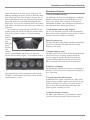
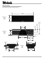
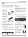
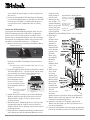
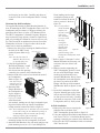
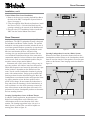
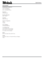
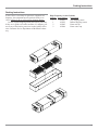
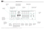
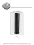
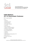
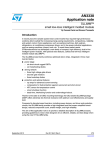
Owner’s Manual XR27 Loudspeaker System XR27 McIntosh Laboratory, Inc. 2 Chambers Street Binghamton, New York 13903-2699 Phone: 607-723-3512 FAX: 607-724-0549 WARNING - TO REDUCE RISK OF FIRE OR ELECTRICAL SHOCK, DO NOT EXPOSE THIS EQUIPMENT TO RAIN OR MOISTURE. NO USER-SERVICEABLE PARTS INSIDE. REFER SERVICING TO QUALIFIED PERSONNEL. IMPORTANT SAFETY INSTRUCTIONS! PLEASE READ THEM BEFORE OPERATING THIS EQUIPMENT. General: 1. Read these instructions. 2. Keep these instructions. 3. Heed all warnings. 4. Follow all instructions. 5. Warning: To reduce risk of fire or electrical shock, do not expose this equipment to rain or moisture. This unit is capable of producing high sound pressure levels. Continued exposure to high sound pressure levels can cause permanent hearing impairment or loss. User caution is advised and ear protection is recommended when playing at high volumes. 6. Only use attachments/accessories specified by the manufacturer. Installation: 7. Install in accordance with the manufacturer’s instructions. 8. Do not install near any heat sources such as radiators, heat registers, stoves, or other equipment (including amplifiers) that produce heat. 9. Do not use this equipment near water. 10. Do not expose this equipment to dripping or splashing and ensure that no objects filled with liquids, such as vases, are placed on the equipment. 11. Use only with the cart, stand, tripod, bracket, or table specified by the manufacturer, or sold with the equipment. When a cart is used, use caution when moving the cart/equipment combination to avoid injury from tip-over. 2 Care of Equipment: 12. Clean only with a dry cloth. 13. Do not permit objects or liquids of any kind to be pushed, spilled and/or fall into the equipment through enclosure openings. Repair of Equipment: 14. Refer all servicing to qualified service personnel. Servicing is required when the equipment has been damaged in any way, liquid has been spilled or objects have fallen into the equipment, the equipment has been exposed to rain or moisture, does not operate normally, or has been dropped. 15. Do not attempt to service beyond that described in the operating instructions. All other service should be referred to qualified service personnel. 16. When replacement parts are required, be sure the service technician has used replacement parts specified by McIntosh or have the same characteristics as the original part. Unauthorized substitutions may result in fire, electric shock, or other hazards. 17. Upon completion of any service or repairs to this product, ask the service technician to perform safety checks to determine that the product is in proper operating condition. Thank You Table of Contents Your decision to own this McIntosh XR27 Loudspeaker System ranks you at the very top among discriminating music listeners. You now have “The Best.” The McIntosh dedication to “Quality,” is assurance that you will receive many years of musical enjoyment from this unit. Please take a short time to read the information in this manual. We want you to be as familiar as possible with all the features and functions of your new McIntosh. Safety Instructions ............................................................. 2 Thank You and Please Take a Moment ............................. 3 Technical Assistance and Customer Service ..................... 3 Table of Contents and Important Information ................... 3 Introduction ....................................................................... 4 Performance Features ........................................................ 5 Dimensions ........................................................................ 6 Installation ....................................................................... 10 How to Connect using a single amplifier ........................ 12 How to Connect using two amplifiers ............................. 14 How to Connect using three amplifiers ........................... 16 Specifications .................................................................. 18 Packing Instruction .......................................................... 19 Please Take A Moment The serial number, purchase date and McIntosh Dealer name are important to you for possible insurance claim or future service. The spaces below have been provided for you to record that information: Serial Number: Purchase Date: Dealer Name: Technical Assistance If at any time you have questions about your McIntosh product, contact your McIntosh Dealer who is familiar with your McIntosh equipment and any other brands that may be part of your system. If you or your Dealer wish additional help concerning a suspected problem, you can receive technical assistance for all McIntosh products at: McIntosh Laboratory, Inc. 2 Chambers Street Binghamton, New York 13903 Phone: 607-723-1545 Fax: 607-723-3636 Customer Service If it is determined that your McIntosh product is in need of repair, you can return it to your Dealer. You can also return it to the McIntosh Laboratory Service Department. For assistance on factory repair return procedure, contact the McIntosh Service Department at: McIntosh Laboratory, Inc. 2 Chambers Street Binghamton, New York 13903 Phone: 607-723-3515 Fax: 607-723-1917 Copyright 2003 by McIntosh Laboratory, Inc. Important Information Caution: The XR27 weight is 84 pounds (38kg) and requires two or more persons to safely handle. 1. Loudspeaker Cables of adequate size are important to ensure that there will be no significant power loss or heating. Cable size is specified in Gauge numbers or AWG (American Wire Gauge). The smaller the Gauge number, the larger the wire size: If the Loudspeaker Cables are 25 feet (7.62m) or less, use at least 18 Gauge (AWG) wire size or larger. If the Loudspeaker Cables are 50 feet (38.1m) or less, use at least 14 Gauge (AWG) wire size or larger. If the Loudspeaker Cables are 100 feet (76.2m) or less, use at least 12 Gauge (AWG) wire size or larger. The Loudspeaker Connection Terminals can accept up to 12 Gauge (AWG) wire. 2. For additional connection information, refer to the owner’s manual(s) for any component(s) connected to the XR27 Loudspeaker System. 3. The XR27 has built-in speaker protection in the form of four automatic resetting solid-state devices as part of the crossover networks. One protects the tweeters, one for the midranges and two for the woofers. The characteristics of this protection are that a certain amount of overdrive is allowed but extended periods of overdrive will trigger protection. If an obvious lack of high, mid or low frequencies is noticed, the Loudspeaker Protection Device may have activated. The protection devices will automatically reset when the volume control is reduced significantly and kept low until the output of the affected Loudspeaker Element returns to normal. 4. When the XR27 Loudspeaker System is driven by more than one amplifier, the output levels of the different amplifiers connected to the Loudspeaker System must be adjusted to achieve a proper balance between the low, midrange and high frequencies reproduced. This adjustment is best achieved through the use of audio test equipment operated by a qualified installer. 5. The XR27 is designed to be used with a Subwoofer, like a McIntosh PS112, in order to hear the entire audible range of sound. 3 Introduction McIntosh Acoustic Engineers have refined the Loudspeaker System concept to provide superior sound quality in a versatile enclosure with five different installation methods. The Low Frequency Section of the System consists of four 8 inch Woofers. They have a large magnet assembly and long cone excursions with very low levels of harmonic distortion and frequency response down to 80Hz. Refer to figure 1. The Woofer also incorporates McIntosh’s Pat- Figure 1 The 6-1/2 inch Midrange Driver also incorporates McIntosh’s Patented LD/HP1 Magnetic Circuit Design with shielding to greatly reduce any external magnetic field. Refer to figures 1, 2 and 3. The low distortion of this Midrange Driver results in the incredible smoothness and clarity in the reproduction of the human voice. The five 1 inch soft dome Tweeters are inline and connected to produce a Bessel Function Array. Refer to figure 4. The indi- Figure 4 1 ented LD/HP Magnetic Circuit Design with shielding to greatly reduce any external magnetic field. Extensive investigating and testing reLD/HP sulted in a new design concept which utilizes a pair of Conventional aluminum shorting sleeves in the magnetic circuit. Refer to figure 2. The sleeves virtually eliminate the negative influence of the fluctuating voice coil field on the permanent magnet field. Figure 2 This results in lower distortion due to more linear magnetic flux in the voice coil gap. Refer to figure 3. Additional benefits are less volume compression due to improved heat transfer through the sleeves and a cooler operating voice coil. Both measurements, as well as critical listening, reveal ten times less distortion than previFigure 3 ous designs. 1 LD/HP Pat. No. 5,151,943 4 vidual tweeter amplitudes and phase relationships are adjusted so the array acts as a high frequency point source. One advantage of such an arrangement is a very smooth and even acoustic polar response. This allows the listener to move off axis without suffering a change in high frequency output. The use of multiple tweeters, combined with a heat sink, also provides greatly increased power handling at high frequencies. The Crossover Networks used in the XR27 Loudspeaker System are designed to ensure an even frequency response over the entire audible range. The Low Frequency Crossover Network is a Third Order design utilizing Capacitors and Inductors with high current capacity. Refer to figure 5. Low Loss (DCR) Inductors in the Low Figure 5 Frequency Network, are chosen not to exhibit any core saturation even at high power levels. This prevents the ad- Introduction and Performance Features Performance Features dition of distortion to the music at low frequencies. The Midrange and High Frequency Crossover Networks utilize both Second and Third Order Crossover Designs. The Capacitors and Inductors used are of a high current capacity design and include low loss (ESR) Polypropylene and Mylar types. The Crossover Networks utilize self resetting high current Poly-Switches to provide an extra measure of protection. The enclosure is an important part of the XR27 Loudspeaker System and consists of a massive extruded aluminum enclosure. Refer to figure 6. The front mounting board is made of 3/4 inch thick MDF that houses the four 8 inch Figure 6 Woofers, one 6-1/2 inch Midrange and the five one inch inline Tweeter Drivers. Refer to figure 7. It has multiple front to • Patented LD/HP Technology The McIntosh Low Frequency and Midrange Loudspeaker Elements feature the patented LD/HP Magnetic Circuit Design. This design, when compared to conventional Loudspeaker Elements, reduces distortion significantly. It also increases power handling and efficiency. • Neodymium-Iron-Boron Alloy Magnets The five one inch Dome Tweeters use Neodymium-IronBoron Alloy that has a high flux density per unit of volume and helps to keep the weight to a minimum. •Bessel Function Array The individual tweeter amplitudes and phase relationships of the five tweeter array are adjusted to act as a high frequency point source • Shielded Magnetic Field The XR27 may be used in Home Theater Installations near a television receiver or monitor without causing the television image to degrade. McIntosh has designed special shielding around the magnetic structure of the XR27 Loudspeaker Elements to prevent interference. • High Power Handling Figure 7 back internal braces to form a dampened rigid Structure. The XR27’s small footprint allows for a variety of different placements in a room. The Loudspeaker Elements and Crossover Components of the XR27 are all chosen for use with powerful amplifiers up to 1,200 watts. • Versatile Operation and Placement In additional to the regular connections, the XR27 Loudspeaker System provides separate connections for Bi-Amplification hookups. The Crossover Network has provisions to ensure the best performance when the Loudspeaker System is mounted in a wall. • Gold Plated Input Connectors The XR27 input connectors are gold plated for superior corrosion resistance and high electrical conductivity. 5 XR27 Dimensions The following dimensions can assist in determining the best location for your XR27 Loudspeaker System. 46-5/8" 118.43cm Front View of the XR27 13-1/16" 33.18cm 10-7/16" 26.51cm 6-1/2" 16.51cm 2-1/2" 6.35cm 10" 25.4cm Rear View of the XR27 10-1/8" 25.72cm 19-5/8" 49.85cm 7-3/8" 18.73cm 9-11/16" 24.60cm 12" 30.48cm 7/8" 2.22cm 1-11/16" 4.29cm 33.18cm 4-7/8" 12.38cm 2-1/8" 5.40cm 6 13-1/16" 7" 17.78cm End Views of the XR27 9-3/16" 23.34cm Dimensions and Installation Installation The XR27 Loudspeaker System requires two or more persons to safely handle during assembly and placement. Follow the instructions below for unpacking and assembly. It is recommended that the Professionals at your McIntosh Dealer, who are skilled in all aspects of installation and operation, install the XR27 Loudspeaker System and any associated audio equipment. Unpacking the Loudspeaker System 1. Remove the banding material from the shipping carton. Refer to figure 8. 2. Lift off the top of the shipping carton and set it aside. 3. Lift up on the rear of the Loudspeaker System, near the foam packing Figure 8 material at both ends. Place the entire assembly (Loudspeaker System, Loudspeaker Grille, On-Wall mounting brackets and foam packing material) next to the bottom shipping carton on a flat surface. Refer to figure 9. 4. Release the Loudspeaker Grille from the packing material by Figure 9 opening the slit in the packing material located on the top center. Remove the Loudspeaker Grille from the protective shipping wrap and set it aside. 5. In a similar manner, lift out the Loudspeaker System and set it aside. 6. Replace the shipping carton top onto the shipping carton bottom. Take the two center pieces of the just removed packing material and lay it down flat onto the top of the shipping carton. 7. Carefully remove the protective shipping bag(s) from the Loudspeaker System so as not to mar the finish or damage the Loudspeaker System Drivers. 8. Place the Loudspeaker System, with the front facing down, on top of the packing material located on top of the shipping carton. Refer to figure 10. Packing material Installation Methods The XR27 may be installed using one of five installation methods listed below: 1. Placing the XR27 horizontally on a flat surface using the attached Stabilizer Bar. 2. Mounting the XR27 vertically on a wall using the supplied Brackets and Hardware. 3. Mounting the XR27 horizontally on a wall using the supplied Bracket and Hardware. 4. Mounting the XR27 vertically or horizontally In-Wall using the optional McIntosh CK27 which includes Brackets, Hardware and a special Loudspeaker Grille. 5. Using the optional McIntosh ST27 Vertical Mount Floor Stand. Proceed to the desired Installation Method that follows. Installation using the Stabilizer Bar 1. Attach the rubber bumpers to the bottom long edge of the XR27 Loudspeaker System and Stabilizer Bar. Refer to figure 11. 2. Loosen, but do not remove, the four screws securing Stabilizer Bar Screws Small Rubber Bumpers Stabilizer Bar Large Rubber Bumpers Figure 11 the Stabilizer Bar to the back of the XR27 Loudspeaker System. Refer to figure 11. 3. Reposition the Stabilizer Bar with the widest side even with the long side edge of the XR27 extruded aluminum enclosure. Refer to figure 12. 4. Tighten the four screws securing the Stabilizer Bar to keep it in place, but not enough to prevent changing the angle of the XR27 in the following steps. 5. The vertical angle of the XR27 may be Figure 12 changed ±5.5 degrees from perpendicular, allowing the sound to be directed upwards or downwards to accommodate the seating arrangement in the room. Refer to figure 13. This can be accomplished by temporarily loosening the four screws and moving the Stabilizer Bar up or Figure 13 Figure 10 7 down. When the desired angle is achieved tighten the four screws. 6. Locate the Loudspeaker Grille and align the fastening pins to the Grommets (there are four pins on each side) on the front of the XR27. Carefully push down to secure the Grille to the Loudspeaker until it is firmly seated. Vertical On-Wall Installation The supplied On-Wall Mounting Brackets allow for two different mounting positions of the XR27 Loudspeaker relative to the wall. The first position is with the Loudspeaker close to and parallel with the wall. The second position places the Loudspeaker further away from the wall and allows for horizontal rotation of ± 30 Degrees. 1. Remove the four screws securing the Stabilizer Bar to Stabilizer Bar Screws Stabilizer Bar Figure 14 the back of the XR27 Loudspeaker System. Refer to figure 14. Note: Save the just removed Stabilizer Bar and screws for possible future use. 2. Using the supplied Allen Wrench and hardware, install four Allen Head 10/32 - 3/4 inch Screws into the openings vacated by the removal of the Stabilizer Bar. 3. Decide on which mounting Remove this Screw position will be used for the Loudspeaker and remove one of the center screws from both ends of the Loudspeaker. Refer to figure 15. Note: Save the just removed screws for possible future use. Figure 15 4. Attach the Nylon Pivot Pin to one of the L Mounting Brackets using the short Pivot Pin Screw and Lock Washer. Refer to figures 16 and 17 for the correct opening location. 5. Attach the other L Mounting Bracket to the Top of the Loudspeaker using the long Pivot Screw and Steel Bushing into the correct opening, based on the desired mounting position. 6. Determine the Loudspeaker Mounting Location on the wall, making sure that the Mounting Brackets will be 8 anchored to the Top and Bottom L Mounting Bracket studs located inOpening for screw, allowside the wall. ing horizontal rotation of 7. Referring to figColumn ures 16 and 17 inOpening for screw, stall the Mounting allowing close to Sleeve on the wall wall mounting (orient with open- Opening for Figure 16 ing at the top) us- Locking Screw ing the supplied Mounting Screws (Phillips Head 1/4 x 1-3/4 inch). 8. Referring to figure 17, measure down from the just mounted L Bracket and install the Bottom L Bracket together with the Shim Plate, using the supplied Mounting Screws (Phillips Head 1/4 x 1-3/4 inch). 9. With two persons, orient the Loudspeaker End with the Top L Bracket above the Mounting Sleeve and carefully line up the bracket with the Figure 17 sleeve. Lower the Loudspeaker onto the Nylon Pivot Point on the Bottom L Bracket while at the same time the Top L Bracket is inserted into the Mounting Sleeve. 10. Install the Locking Screw together with the Flat Washer into the opening on the Top L Bracket to secure the Loudspeaker. 11. Locate the Loudspeaker Grille and align the fastening pins to the Grommets on the front of the XR27 (there Installation, con’t are four pins on each side). Carefully push down to secure the Grille to the Loudspeaker until it is firmly seated. Horizontal On-Wall Installation The supplied Horizontal On-Wall Mounting Bracket allows for mounting the XR27 Loudspeaker onto a wall. The Loudspeaker may be rotated ±15 Degrees allowing for placement either above or below a TV/Monitor/Screen. The XR27 Loudspeakers’s Smooth Frequency Response may be altered by large object(s) located in sound waves path or by locating the column too close to a floor or ceiling. There should be an unobstructed area in front of the Loudspeaker of at least 15 degrees either side from the center axis for the best performance. 1. Remove the four screws securing the Stabilizer Bar to the back of the XR27 LoudRemove these Screws speaker System. Refer to figure 14. Note: Save the just removed Stabilizer Bar and screws for possible future use. 2. Using the supplied Allen Wrench and hardware, install four Allen Head 10/32 - 3/4 Figure 18 inch Screws into the openings vacated by the removal of the Stabilizer Bar. 3. Remove both of the center screws from both ends of the Loudspeaker. Refer to figure 18. Note: Save the just removed screws for possible future use. 4. Attach the Wall Hanger Bracket to the Loudspeaker using the supplied mounting screws Figure 19 (1/4 x 1-1/2 inch Allen Head) and lock washers, making sure the large rectangular opening on the bracket lines up with the Loudspeaker hookup terminal connections. Refer to figure 19. Note: The Loudspeaker may be mounted closer and parallel to the wall by using the two additional openings on the Wall Hanger Bracket instead of the openings allowing rotation of the Loudspeaker. 5. Use a suitable wall stud finder to verify a proper mounting location for the Loudspeaker on the wall. 6. Attach the Wall Bracket to the wall studs using the supplied mounting screws (8 x 2-1/2 inch Phillips Flat Head) making sure the large rectangular opening on the bracket is located on the left side as you face it. Refer to figure 20. Note: It is important to anchor the Wall Bracket to at least three wall studs, using three mounting screws per stud. The large rectangular opening on the left side of the Wall Bracket Figure 20 allows for the optional routing of the Loudspeaker Hookup Wire inside the wall. 7. Refer to pages 11 through 13 in this Manual and make the necessary connections to the rear of the Loudspeaker. 8. With two persons supporting the XR27 Loudspeaker, position it with the rear of the Wall Hanger almost touching the wall and above the mounted Wall Bracket. Slowly lower the Loudspeaker down and align the top bent over portion of the Wall Hanger with the top of the mounted Wall Bracket. Refer to figures 21 and 22. 9. Locate the Loudspeaker Grille and align the fastening pins to the Grommets on the front of the XR27 (there are four pins on each side). Carefully push down to secure the Grille to the Loudspeaker until it is firmly seated. Figure 21 In-Wall Installation 1. Remove the four screws securing the Figure 22 Stabilizer Bar to the back of the XR27 Loudspeaker System. Refer to figure 14. 2. Using the supplied Allen Wrench and hardware, install four screws (10/32 x 3/4 inch Allen Head) into the openings vacated by the removal of the Stabilizer Bar. 3. Proceed to the CK27 Installation Guide to install the XR27 into the wall. 9 Room Placement Installation, con’t Vertical Mount Floor Stand Installation 1. Remove the four screws securing the Stabilizer Bar to the back of the XR27 Loudspeaker System. Refer to figure 14 on page 8. 2. Using the supplied Allen Wrench and hardware, install four screws (10/32 x 3/4 inch Allen Head) into the openings vacated by the removal of the Stabilizer Bar. 3. Proceed to the ST27 Installation Guide to install the XR27 into the Vertical Mount Floor Stand. Room Placement Loudspeaker placement in a room can greatly affect performance. The XR27 Loudspeaker System is designed for both Music and Home Theater Systems. The optimal method for selecting speaker locations includes the use of a real time spectrum analyzer operated by an experienced system installer. An uncompromising installation would take into consideration the floor, wall and ceiling coverings, the type and placement of furniture and can even include the architectural design of the room and its construction materials. In those instances where placement in the room is fixed, an environmental equalizer may be needed to restore proper musical balance. Placement near a wall, corner, floor, ceiling or any intersecting surfaces will reinforce some bass frequencies. Which bass frequencies are boosted by placement in a particular location is dependent on the dimensions of the room. Test the various Loudspeaker locations by playing music with continuous bass, setting up the speakers and listening to them from the main listening spot. Move the Loudspeakers to an alternate location and repeat the listening, paying attention to how the bass qualities and response levels change. Do not assume the loudest bass is best; rather listen for booming (a lack of articulation), as well as a balance over the whole spectrum, to assure the bass will not drown out the other parts of the music. Experiment with various Loudspeaker positions to determine the best sounding location. Locating Loudspeakers for use in Home Theater In a Home Theater application, the placement of Left and Right Front Loudspeakers can be limited by such considerations as the size and location of the video monitor. The locating suggestions in the “for use in a Music System” section below can still be helpful as a starting place. Refer to figure 18. 10 Figure 18 Locating Loudspeakers for use in a Music System When used in a Music System the distance between the Loudspeakers and the listener to the Loudspeakers should form an isosceles triangle. If the speakers are too far apart relative to the listener, some imaging can be lost. Refer to figure 19. Figure 19 How to Connect using a single Amplifier How to Prepare Hookup Cables Connections using a single Amplifier The McIntosh XR27 Loudspeaker System utilizes binding posts for speaker wire connections. Prepare the Loudspeaker Hookup Cables that attach to the Power Amplifier Output Terminals: Bare wire cable ends: Carefully remove sufficient insulation from the cable ends, refer to figures 20, 21 & 22. If the cable is stranded, carefully twist the strands together as tightly as possible. 1. Connect a Loudspeaker cable from the Negative (-) Binding Post of the Amplifier to the XR27 LOW COMmon (-) Binding Post. 2. Connect a Loudspeaker cable from the Positive (+) Binding Post of the Amplifier to the XR27 LOW 4S (+) Binding Post. Note: If desired, the twisted ends can be tinned with solder to keep the strands together and/or attach a spade lug. Note: The LOW and MID/HIGH COMmon (-) Binding Posts must have a jumper installed between them. Likewise the LOW and MID/HIGH 4S (+) Binding Posts must also have a jumper installed between them. If the XR27 Loudspeaker is installed into wall, use the IN-WALL Binding Posts instead of the LOW Binding Posts. 3. Tighten all of the Loudspeaker and Amplifier Binding Posts. McIntosh Single Channel Amplifier Spade lug or prepared wire connection: Insert the spade lug connector or prepared section of the cable end into the terminal side access hole, and tighten the terminal cap until the cable is firmly clamped into the terminal so the wires cannot slip out. Refer to figures 23, 24 & 25. 11 How to Prepare Hookup Cables The McIntosh XR27 Loudspeaker System utilizes binding posts for speaker wire connections. Prepare the Loudspeaker Hookup Cables that attach to the Power Amplifier Output Terminals: Bare wire cable ends: Carefully remove sufficient insulation from the cable ends, refer to figures 20, 21 & 22. If the cable is stranded, carefully twist the strands together as tightly as possible. Note: If desired, the twisted ends can be tinned with solder to keep the strands together and/or attach a spade lug. Spade lug or prepared wire connection: Insert the spade lug connector or prepared section of the cable end into the terminal side access hole, and tighten the terminal cap until the cable is firmly clamped into the terminal so the wires cannot slip out. Refer to figures 23, 24 & 25. McIntosh Single Channel Amplifier Number Two How to Connect using two Amplifiers 1. Remove the jumpers between the LOW and MID/HIGH Binding Posts and save them for possible future use. 2. Connect a Loudspeaker cable from the Negative (-) Binding Post of the Amplifier Number One to the XR27 LOW COMmon (-) Binding Post. Note: If the XR27 Loudspeaker is installed into wall, use the IN-WALL Binding Posts instead of the LOW Binding Posts. 3. Connect a Loudspeaker cable from the Positive (+) Binding Post of the Amplifier Number One to the XR27 LOW 4S (+) Binding Post. 4. Connect a Loudspeaker cable from the Negative (-) Binding Post of the Amplifier Number Two to the XR27 MID/HIGH COMmon (-) Binding Post. 5. Connect a Loudspeaker cable from the Positive (+) Binding Post of the Amplifier Number Two to the XR27 MID/HIGH 4S (+) Binding Post. 6. Tighten all of the Loudspeaker and Amplifier Binding Posts. 12 McIntosh Single Channel Amplifier Number One How to Connect using two Amplifiers 13 Specifications Specifications System Driver Complement Four 8 inch Woofers One 6.5 inch Midrange Five 1 inch Dome Tweeters Impedance 4 ohms Nominal Frequency Response 80Hz - 20kHz Sensitivity 89dB (2.8V/1m) Crossover Frequencies 275Hz 2,800Hz Power Handling 1200 Watts Maximum Overall Dimensions 13-1/16 inches (33.18cm) Height 46-5/8 inches (118.43cm) Width 5-3/4 inches (14.61cm) Depth Finish Black Ash, Natural Cherry, Red Cherry Weight 84 pounds (38 kg) net, 105 pounds (48 kg) in shipping carton 14 Packing Instructions Packing Instructions In the event it is necessary to repack the equipment for shipment, the equipment must be packed exactly as received. Failure to do so will result in shipping damage. Use the original shipping carton and interior parts only if they are in good serviceable condition. If a shipping carton or any of the interior part(s) are needed, please call or write Customer Service Department of McIntosh Laboratory. High Frequency Section Column Quantity Part Number Description 1 034221 Top shipping carton 1 034222 Bottom shipping carton 2 034205 Foam end cap 2 034206 Foam center cap 15 McIntosh Laboratory, Inc. 2 Chambers Street Binghamton, NY 13903 The continuous improvement of its products is the policy of McIntosh Laboratory Incorporated who reserve the right to improve design without notice. Printed in the U.S.A. McIntosh Part No. 04085501