1
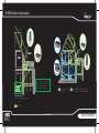
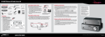
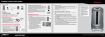
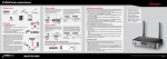
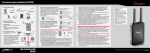
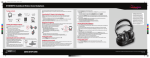
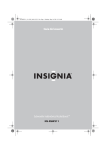
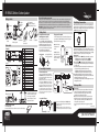
RF-RBWSO2 Wireless Outdoor Speaker
Please read before setting up your system.
Package contents
3.5mm stereo
female to 2-RCA male
cable (6 inches/15.25 cm)
DC adapter
for wireless
speaker
IR remote
Every Rocketboost network must contain at least one hub device, which directs network data traffic and helps devices join the
network. The network can have only one hub, which you can enable using the Hub switch on the back of all Rocketboost
transmitters. See your User Guide for instructions on “joining” devices to the network. If this is your first Rocketboost product you
should make this unit the hub, if you already have Rocketboost products, you should disable the hub mode on this device.
IMPORTANT: Hub units must always have power for your network to operate. The device may be placed in standby, but the unit
must remain plugged into the wall to operate your network.
e
Guid
User
1 Getting Started
E
GUID
TUP
CK SE
QUI
TM
DC adapter
for transmitter
Sender
3.5 mm
stereo cable
Wireless speaker
User Guide
Quick
Setup Guide
Front controls
TM
TM
1 2
Front Panel
4
3
5
Speaker
6
BASS
CHARGE
VOL
VOL
So
ur
ce
2
6
POWER
/
/JOIN
Front Panel
1
TX LED
Load batteries in wireless speaker
(Installing batteries is optional)
A Unscrew the bottom cover ( 3 screws).
B Insert eight alkaline or rechargeable NiMH batteries
matching +/- as indicated. This product will only recharge
NiMH batteries. Do not attempt to charge any other
batteries in this product. Note: Your wireless speaker can
operate on batteries or with the DC to AC adapter (provided).
Transmitter
3
4
8
4
CHANNEL
L - MONO - R
12
SOURCE
11
5
7
5
9
10
7
#
1
2
3
4
5
6
7
#
1
2
3
4
5
6
7
8
9
10
11
12
Feature
Power/Join button
Power/Join indicator (Blue/Green Light)
Standby indicator (Red Light)
IR sensor window
The unit will charge and play simultaneously.
C Replace the cover and fasten the three screws.
Wireless speaker
8 rechargeable or alkaline
C batteries (not included)
Source button
Receiver-mode indicator (Blue Light)
Sender-mode indicator (Blue Light)
Feature
Volume increase/decrease dial
Power/on standby/Join button
Source
Middle-treble reflex hole
Bass reflex hole
Power/Join indicator (Red/Blue light)
BASS indicator
Charge indicator
Channel MONO (L/R) indicators
Audio source signal indicator
DC adaptor in
Bass Boost
Adjust antennas
Pull up the antennas
Preparing the remote control
To activate the battery:
Remove the tab from the bottom of the remote control to enable the battery.
3 Establishing Communication
If this is your first Rocketboost product and you do not have an existing Rocketboost
network, the devices were joined at the factory. You do not need to join them. If you are
adding these devices to an existing network, change the hub mode switch on the sender
to Disabled and then join BOTH devices to your existing hub.
For best results, adjust the antennas to
vertical. In some instances, you may
improve range by rotating both
antennas 45 degrees to create a 90°
angle similar to a wide "V".
Charge your wireless speaker
Connect the DC adapter to the wireless speaker and plug into an AC
power outlet. The CHARGE LED blinks green while it is charging. The
light will be solid when charging is complete.
Note: For the first time,
charge batteries for
16 hours.
15V DC
Caution: Only use the
supplied power adapter
and make sure your outlet
matches the AC’s input
of 100-240 V.
x8
BASS
15V DC
Wireless speaker’s
back panel
2 Connecting the Transmitter
Connect to an audio source
OR
Connect one end of the audio cable (supplied) to
the AUDIO IN jack on the sender and the other end
to the audio output jack of your device (such as an
A/V receiver, PC, or iPod.)
Note: If you are adding this sender to an existing network,
set the hub switch to Disable and follow the instructions
under Establishing Communication to add the transmitter
and speaker to your existing network. Otherwise, leave it
on Enable as the transmitter and wireless speaker were
pre-configured at the factory and you will not need to go
through the Establish Communication steps. Remember to
turn the volume up on the source device to at least 80%
of its maximum volume.
Supplied
Use this procedure only if you need to rejoin the transmitter and speaker. This procedure
is not required for normal operation as devices were joined at the factory. To connect
these devices to an existing hub device that you own, follow the same instructions: Join
the sender/receiver to your existing hub, then join the wireless speaker to your existing
hub. Note: You can only join devices to the hub unit (the one with the green LED).
Rocketboost device
A Set the HUB STATUS switch to ENABLE if this is your first Rocketboost product set.
• The LED lights green when the HUB STATUS switch is set to ENABLE.
• The LED lights blue when the HUB STATUS switch is set to DISABLE.
B Press and hold the button on the sender/receiverfor more than three seconds to
put it into joining mode. The LED starts blinking rapidly and the unit will stay in Join
mode for 30 seconds.
C Press the Power/Join button on the wireless speaker for more than three seconds
so the sender and wireless speaker will enter connection mode.
• The LED lights steadily if the link is activated between both of the units.
• The LED blinks at a slower rate if the communication link is not successful.
D Once the link is established, if the Source LED on the wireless speaker is not
illuminated, press the Source button to toggle to the next source. If the LED is still
not illuminated, check that your source is powered up.
For further details, see instructions in the user manual for joining new devices to an
existing Rocketboost network.
Supplied
4 Listening to Music
To audio
output jack
To audio
output jack
Connect the AC Adapter
Connect one end of the adapter to the DC IN jack, then
plug the other end into an AC power outlet. The standby
indicator turns red.
Note: Make sure that the power outlet is 100-240V, and do not
connect the AC adapter until all other connections are completed.
To listen to music:
A Turn on the sender and the wireless speaker. Make sure that the wireless
speaker is fully charged (if using Batteries) and there is an active link
between the sender and the wireless speaker. An active link will be
indicated by the Power LED showing a solid blue.
B Make sure the volume is turned up to about 80% of maximum volume.
C Adjust the volume level on your wireless speaker. If you have multiple
streams in your Rocketboost network, press the Source button on the
wireless speaker to hear the next stream.
Repeated pressing of the SOURCE button will toggle through available
sources.
ENGLISH 09-0536
QUICK SETUP GUIDE
RF-RBWSO2 Wireless Outdoor Speaker
Please read before setting up your system.
Package contents
3.5mm stereo
female to 2-RCA male
cable (6 inches/15.25 cm)
DC adapter
for wireless
speaker
IR remote
Every Rocketboost network must contain at least one hub device, which directs network data traffic and helps devices join the
network. The network can have only one hub, which you can enable using the Hub switch on the back of all Rocketboost
transmitters. See your User Guide for instructions on “joining” devices to the network. If this is your first Rocketboost product you
should make this unit the hub, if you already have Rocketboost products, you should disable the hub mode on this device.
IMPORTANT: Hub units must always have power for your network to operate. The device may be placed in standby, but the unit
must remain plugged into the wall to operate your network.
15
0F
EE
T
e
Guid
User
1 Getting Started
E
GUID
TUP
CK SE
QUI
TM
DC adapter
for transmitter
Sender
User Guide
3.5 mm
stereo cable
Wireless speaker
TM
TM
OFFICE
4
3
5
Speaker
7
POWER
/
/JOIN
Front Panel
6
BASS
7
CHARGE
8
LIVING ROOM
So
ur
ce
VOL
3
4
4
CHANNEL
L - MONO - R
12
SOURCE
11
5
9
10
5
RF-RBWSO2
Adjust antennas
Pull up the antennas
Preparing the remote control
#
1
2
3
4
5
6
7
8
9
10
11
12
Feature
Power/Join button
Power/Join indicator (Blue/Green Light)
The unit will charge and play simultaneously.
C Replace the cover and fasten the three screws.
OUTDOOR
Wireless speaker
Standby indicator (Red Light)
IR sensor window
Source button
Receiver-mode indicator (Blue Light)
Sender-mode indicator (Blue Light)
8 rechargeable or alkaline
C batteries (not included)
RF-RBWSO2*
SENDER
Connect the DC adapter to the wireless speaker and plug into an AC
power outlet. The CHARGE LED blinks green while it is charging. The
light will be solid when charging is complete.
Note: For the first time,
charge batteries for
16 hours.
15V DC
RF-RBREC*
Caution: Only use the
supplied power adapter
and make sure your outlet
matches the AC’s input
of 100-240 V.
x8
BEDROOM
Volume increase/decrease dial
Power/on standby/Join button
Source
Middle-treble reflex hole
Bass reflex hole
Power/Join indicator (Red/Blue light)
BASS indicator
Charge indicator
Channel MONO (L/R) indicators
Audio source signal indicator
DC adaptor in
Bass Boost
15V DC
Wireless
speaker’s
RF-RBREC
back panel
LIVING ROOM
To activate the battery:
Remove the tab from the bottom of the remote control to enable the battery.
RF-RBWSO2
KITCHEN
2 Connecting the Transmitter
Connect to an audio source
Connect one end of the audio cable (supplied) to
the AUDIO IN jack on the sender and the other end
to the audio output jack of your device (such as an
A/V receiver, PC, or iPod.)
RF-RBKIT*
pre-configured at the factory and you will not need to go
through the Establish Communication steps. Remember to
turn the volume up on the source device to at least 80%
of its maximum volume.
OR
RF-RBKIT
(SENDER)
Note:
you are adding
sender to an existing network,
There is only
on IfSpeaker
and this
Sender/Receiver
the hub switch to Disable and follow the instructions
included inset
the
box,
however
the
unit can
under Establishing Communication to add the transmitter
operate simultaneously
as existing
a sender
and Otherwise, leave it
and speaker to your
network.
on Enable asinthe
transmitter
and wireless speaker were
receiver as depicted
the
diagrams.
For best results, adjust the antennas to
vertical. In some instances, you may
improve range by rotating both
*Upgrades your existing audio products to wireless
antennas 45 degrees to create a 90°
angle similar to a wide "V".
INCLUDED
OFFICE
BASS
SPEAKER Feature
ET
150 FE
2
6
#
1
2
3
4
5
6
7
15
0F
EE
T
Charge your wireless speaker
RF-RBKIT
(RECEIVER)
Use this procedure only if you needRF-RBWSO2*
to rejoin the transmitter and speaker. This procedure
is not required for normal operationRECEIVER
as devices were joined at the factory. To connect
these devices to an existing hub device that you own, follow the same instructions: Join
the sender/receiverOUTDOOR
to your existing hub, then join the wireless speaker to your existing
hub. Note: You can only join devices to the hub unit (the one with the green LED).
Rocketboost device
A Set the HUB STATUS switch to ENABLE if this is your first Rocketboost product set.
• The LED lights green when the HUB STATUS switch is set to ENABLE.
• TheRF-RBWS02
LED lights blue when the HUB STATUS switch is set to DISABLE.
B Press and hold the button on the sender/receiverfor more than three seconds to
put it into joining mode. The LED starts blinking rapidly and the unit will stay in Join
mode for 30 seconds.
RF-RBWS02
C Press the Power/Join button on the wireless speaker
for more than three seconds
SPEAKER
so the sender and wireless speaker will enter connection mode.
• The LED lights steadily if the link is activated between both of the units.
• The LED blinks at a slower rate if the communication link is not successful.
D Once the link is established, if the Source LED on the wireless speaker is not
illuminated, press the Source button to toggle to the next source. If the LED is still
not illuminated, check that your source is powered up.
For further details, see instructions in the user manual for joining new devices to an
existing Rocketboost network.
ET
150 FE
1 2
Front Panel
VOL
A Unscrew the bottom cover ( 3 screws).
B Insert eight alkaline or rechargeable NiMH batteries
matching +/- as indicated. This product will only recharge
NiMH batteries. Do not attempt to charge any other
batteries in this product. Note: Your wireless speaker can
operate on batteries or with the DC to AC adapter (provided).
Transmitter
1
Quick
Setup Guide
TX LED
Load batteries in wireless speaker
(Installing batteries is optional)
RF-RBWS02
SPEAKER
Front controls
3 Establishing Communication
If this is your first Rocketboost product and you do not have an existing Rocketboost
network, the devices were joined at the factory. You do not need to join them. If you are
adding these devices to an existing network, change the hub mode switch on the sender
to Disabled and then join BOTH devices to your existing hub.
*Upgrades your existing audio products to wireless
Supplied
Supplied
4 Listening to Music
To audio
output jack
INCLUDED: CONNECT
UP
To audio
TO 2 ROOMS
output jack
Connect the AC Adapter
Connect one end of the adapter to the DC IN jack, then
plug the other end into an AC power outlet. The standby
indicator turns red.
Note: Make sure that the power outlet is 100-240V, and do not
connect the AC adapter until all other connections are completed.
listen to music:
NOTTo
INCLUDED:
OTHER ROCKETBOOST PRODUCTS
Turn on theUP
sender
the wireless
Make sure that the wireless
(CANACONNECT
TO 9and
ROOMS
WITHspeaker.
ONE SENDER)
speaker is fully charged (if using Batteries) and there is an active link
between the sender and the wireless speaker. An active link will be
indicated by the Power LED showing a solid blue.
B Make sure the volume is turned up to about 80% of maximum volume.
C Adjust the volume level on your wireless speaker. If you have multiple
streams in your Rocketboost network, press the Source button on the
wireless speaker to hear the next stream.
Repeated pressing of the SOURCE button will toggle through available
sources.
ENGLISH 09-0536
QUICK SETUP GUIDE