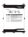
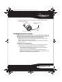
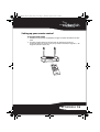
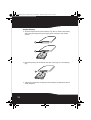
1
RF-RBWS02_09-0535_MAN_ENG_V1.fm Page 1 Thursday, August 27, 2009 7:39 PM
Wireless Outdoor Speaker
RF-RBWS02
User Guide
RF-RBWS02_09-0535_MAN_ENG_V1.fm Page 2 Thursday, August 27, 2009 7:39 PM
Wireless Outdoor Speaker
Contents
Important safety instructions ..................................... 3
Features............................................................................... 6
Using your outdoor speaker kit................................21
Troubleshooting ............................................................26
Specifications..................................................................27
Legal notices ...................................................................28
One-year limited warranty .........................................31
Introduction
Congratulations on your purchase of a Rocketfish Wireless Outdoor
Speaker Kit that is part of the Rocketboost™ system. The Rocketboost
system implements an expandable Wireless Audio distribution
technology which is compatible with all Rocketboost products. All
Rocketboost products use a proprietary 2.4GHz communication
technology.
Simply combine the sender/receiver with the wireless speaker and
start enjoying music anywhere. With a 150-foot broadcast range, this
powerful wireless speaker system transmits through walls, floors, and
ceilings without the hassle of running wires. The main controls are
located on the wireless speaker itself, so you won't have to run back
and forth to adjust the volume. Red and blue lighting illuminates the
2
RF-RBWS02_09-0535_MAN_ENG_V1.fm Page 3 Thursday, August 27, 2009 7:39 PM
wireless speaker for convenient operations at night. The speaker
operates on eight batteries or from a wall socket using an AC adapter,
and offers you rich sounding bass and crisp treble.
The lightning flash with arrowhead symbol,
within an equilateral triangle is intended to
alert the user to the presence of
uninsulated "dangerous voltage" within
the product's enclosure that may be of
sufficient magnitude to constitute a risk of
electric shock to persons.
The exclamation point within an equilateral
triangle is intended to alert the user to the
presence of important operating and
maintenance (servicing) instructions in the
literature accompanying the appliance.
CAUTION:
TO REDUCE THE RISK OF ELECTRIC SHOCK:
DO NOT REMOVE SCREWS, COVERS OR THE CABINENT.
NO USER SERVICING PARTS INSIDE.
REFER SERVICING TO QUALIFIED SERVICE PERSONNEL.
Important safety instructions
Read these instructions.
Keep these instructions.
Heed all warnings.
Follow all instructions.
Do not use this apparatus near water.
Clean only with a dry cloth.
Do not block any ventilation openings. Install in accordance with the
manufacturer's instructions.
8 Do not install near any heat sources such as radiators, heat registers,
stoves, or other apparatus (including amplifiers) that produce heat.
1
2
3
4
5
6
7
RF-RBWS02 3
RF-RBWS02_09-0535_MAN_ENG_V1.fm Page 4 Thursday, August 27, 2009 7:39 PM
9 Do not defeat the safety purpose of the polarized or grounding-type
10
11
12
13
14
15
16
plug. A polarized plug has two blades with one wider than the other. A
grounding type plug has two blades and a third grounding prong. The
wide blade or the third prong are provided for your safety. If the
provided plug does not fit into your outlet, consult an electrician for
replacement of the obsolete outlet.
Protect the power cord from being walked on or pinched particularly at
plugs, convenience receptacles, and the point where they exit from the
apparatus.
Only use attachments/accessories specified by the manufacturer.
Unplug this apparatus during lightning storms or when unused for long
periods of time.
Refer all servicing to qualified service personnel. Servicing is required
when the apparatus has been damaged in any way, such as
power-supply cord or plug is damaged, liquid has been spilled or objects
have fallen into the apparatus, the apparatus has been exposed to rain or
moisture, does not operate normally, or has been dropped.
To reduce the risk of fire or electric shock, do not expose this device to
rain, moisture, dripping, or splashing, and no objects filled with liquids,
such as vases, shall be placed on it.
The wall plug is the disconnecting device. The plug must remain readily
operable.
Batteries should not be exposed to excessive heat such as sunshine, fire,
or the like.
Caution: Danger of explosion if battery is incorrectly replaced. Replace only with the
same or equivalent type.
Warning: Read the Rating Label on the bottom of the unit for power input and other
safety information.
Caution - Proper Installation
Install the system in a place which is level, dry and neither too hot nor too cold. The
appropriate temperature is between 5° C and 35° C.
Install the system in a location with adequate ventilation to prevent internal heat
from building up inside the unit.
Caution - Proper ventilation
To avoid risk of electric shock and fire, and to prevent damage, locate
the apparatus for adequate ventilation.
4
RF-RBWS02_09-0535_MAN_ENG_V1.fm Page 5 Thursday, August 27, 2009 7:39 PM
How does Rocketboost™ work?
Rocketboost technology can connect all audio devices throughout
your home to form a convenient, private, and secure home audio
network.
Every Rocketboost network must contain a device called a manager,
which directs network data traffic and helps devices join the network.
The network can have only one manager, which is selected using the
Hub switch on the back of all Rocketboost transmitters. See the User
Guide for instructions on joining devices to the network.
Each transmitter sends its own, two-channel stereo signal around the
network, and any receiver can access the audio signal from any of the
transmitters.
Rocketboost also features an innovative volume control that can be
changed at the receiver or the transmitter. For example, when the
stream's volume level is changed, all receivers listening to that stream
have the same change in volume.
Rocketboost also features a global mute feature that instantly
silences all connected devices. When turning off mute, only the
stream that received the “unmute” command is effected.
We hope you enjoy your new Rocketboost system. Remember that
it's designed to grow with your home entertainment needs, and that
it's easy to add a new device to the network as you expand your
entertainment system.
POWER /JOIN
BASS
CHARGE
CHANNEL
L - MONO - R
SOURCE
TM
TM
TM
Manager
TM
RF-RBWS02 5
RF-RBWS02_09-0535_MAN_ENG_V1.fm Page 6 Thursday, August 27, 2009 7:39 PM
Features
• 2.4 GHz unlicensed band operation
• Up to 150 feet (45 meters) unobstructed operating range with minimal
signal delay and interference
• Wireless digital audio
• Stereo sound speaker option (when used with a second speaker)
• 2-in-1 power/join control combines controls into one easy-to-use
package
• Built-in charger for recharging the optional NiMH rechargeable batteries
Package contents
Examine the contents of the box for your wireless speaker kit. The
box should contain:
•
•
•
•
•
•
•
•
•
6
Wireless sender/receiver
Wireless speaker
Rocketboost IR remote control
AC to DC adapter (for the wireless sender/receiver)
AC to DC adapter (for the wireless outdoor speaker)
User Guide
Quick Setup Guide
3.5mm Stereo Male to Male Cable (6 feet)
3.5mm Stereo Female to 2 RCA Male Cable (6 inches)
RF-RBWS02_09-0535_MAN_ENG_V1.fm Page 7 Thursday, August 27, 2009 7:39 PM
Front panel
TM
1
2
3
4
5
6
7
#
Feature
Description
1
Power/Join button
Press to turn the sender/receiver on, then hold to initiate joining. Press again to go into
standby. Upon insertion of the AC adapter, the unit powers up automatically.
Lights blue when the HUB STATUS is set to “DISABLE”.
Lights green when the HUB STATUS is set to “ENABLE”.
The LED will show a solid illumination when it is joined in a network, if the unit is not in a
network the LED will flash slowly. When the unit is put in joining mode the LED will flash
rapidly.
Turns red when the sender/receiver is in standby mode.
Power/Join indicator
2
3
Standby LED
4
IR sensor window
Receives the signal from the remote control.
5
Source
6
Receiver-mode LED
7
Sender-mode LED
Press the next source button to move to the next source. Each press of the button will toggle
to the next source.
Turns blue when receiving signals. Note: This LED will not be lit if the source unit is turned off
or is no longer sending audio. Press the Source button to find the next available source.
Turns blue when sending signals. Note: This LED will light automatically when a 3.5 mm
connector is attached to the unit, as the device senses the cable connection.
RF-RBWS02 7
RF-RBWS02_09-0535_MAN_ENG_V1.fm Page 8 Thursday, August 27, 2009 7:39 PM
Back panel
1
2
3
4
1
#
1
Feature
Description
External antenna
Receives signals from external senders. Sends signals to external receivers.
2
DC IN jack
Plug the AC adapter into this jack.
AUDIO IN/OUT jacks
When used as a sender, plug an external audio source into the AUDIO IN jack.
When used as a receiver, plug your speaker system into the AUDIO OUT jack. Please note, this
device operates as either a sender and/or receiver, so you can use it simultaneously to send and
receive on your Rocketboost network.
Enables/disables hub mode operation. Please see the “Establishing communication” section on
page 21 for more information.
3
4
8
HUB STATUS switch
RF-RBWS02_09-0535_MAN_ENG_V1.fm Page 9 Thursday, August 27, 2009 7:39 PM
Wireless speaker - front
POWER
/
/JOIN
6
BASS
VOL
VOL
POWER /JOIN
SO
UR
CE
1
2
CHARGE
BASS
CHARGE
7
8
CHANNEL
L - MONO - R
SOURCE
3
CHANNEL
L - MONO - R
4
TM
4
SOURCE
5
9
10
#
Feature
Description
1
Volume control knob
Turn this knob to increase or decrease the volume.
3
Power on/
Standby/Join
Source button
Press to turn the speaker on, then hold to initiate joining. Press again to go to
standby.
Press to select an audio source from one of the connected sources.
4
Middle-treble reflex port
Middle-treble frequencies are directed through this port.
5
Bass reflex port
Bass frequencies are directed through this port.
Power/Join indicator
Lights red when in standby mode.
Blinks (blue) quickly when the speaker is in pairing mode.
Blinks (blue) slowly when the speaker is not connected to a hub device.
Lights steady blue when the sender/receiver and the speaker are successfully
linked.
Lights when bass enhancement is turned on.
2
6
7
Bass indicator
Charge indicator
8
Lights green to indicate a full charge.
Slowly blinking green indicates that the batteries need charging.
Quickly blinking green indicates that the batteries need replacing.
RF-RBWS02 9
RF-RBWS02_09-0535_MAN_ENG_V1.fm Page 10 Thursday, August 27, 2009 7:39 PM
#
Feature
9
Channel MONO (L/R)
indicators
10
Description
If two wireless outdoor speakers are connected to the sender, left lights when the
left audio channel is on and right lights when the right audio channel is on.
If both channels are on simultaneously, both left and right light, indicating mono
mode.
Audio source signal indicator Lights when there is an active link and the speaker receives audio signals from a
sender. The LED will be off if the transmitter it was previously listening to is not
powered.
Wireless speaker - back
BASS
1
15V DC
2
BASS
15V DC
#
Feature
Description
BASS button
Toggles the operation of the Bass Boost feature. Also performs
the Stereo Trim mode. See “Using two wireless speakers as a
stereo pair” on page 24 for more information.
Plug the AC adapter into this jack.
1
2
10
DC IN jack
RF-RBWS02_09-0535_MAN_ENG_V1.fm Page 11 Thursday, August 27, 2009 7:39 PM
Remote control
4
1
5
2
6
7
8
3
TM
#
1
Feature
Description
/| Standby/On button
Volume
/
2
3
BASS button
4
Input A
5
Input B
buttons (device)
Press to turn the sender/receiver or wireless speaker on. Press again to go
to standby.
Press to adjust the volume of the device. The sender/receiver is a line level
device, so this will only operate the volume control on the speaker. The
volume on the local amplifier or powered speakers will need to be
adjusted when listening to the sender/receiver's line level out.
Press to enable/disable the BASS enhancement.
Press to toggle between SPEAKER Input A or Pre-In A of the sender (only
applies to RF-RBKIT - purchased separately for the Rocketboost system).
Press to toggle between the audio sources connecting SPEAKER Input B or
Pre-In B of the sender (only applies to RF-RBKIT - purchased separately for
the Rocketboost system).
RF-RBWS02 11
RF-RBWS02_09-0535_MAN_ENG_V1.fm Page 12 Thursday, August 27, 2009 7:39 PM
#
Feature
6
Volume
7
8
Description
buttons (stream) Press to adjust the volume of all devices receiving the same audio stream.
Press to mute all devices. Press again to unmute the stream that receives
(mute - all)
the IR command. To unmute other streams, you must point the remote
control at a device muted for that stream.
Next Source button
Press to select the next source.
/
Setting up your wireless speaker kit
Powering your wireless speaker
To connect your wireless speaker to an AC power outlet:
1 Connect one end of the power cord to the DC IN connector on the back
of the speaker.
2 Plug the other end of the power cord into an AC power outlet. The power
indicator on the speaker turns on and goes into standby mode.
Battery operation
Your Wireless speaker is compatible with either Alkaline or NiMH
rechargeable batteries. It uses auto-sensing technology which allows
the unit to detect which type of batteries are used, so there is nothing
you have to do. Make sure that you only use either Alkaline or NiMH
rechargeable batteries.
To load batteries into the wireless speaker:
1 Remove the three screws holding the bottom cover on the wireless
speaker, then remove the cover.
2 Insert eight NiMH rechargeable or alkaline batteries into the battery
compartment, making sure that the polarity (+ and -) on the batteries
matches the markings inside the battery compartment.
12
RF-RBWS02_09-0535_MAN_ENG_V1.fm Page 13 Thursday, August 27, 2009 7:39 PM
3 Replace the bottom cover on the speaker and fasten with the three
screws you removed.
8 NiMH C cells or alkalines
(not provided)
Bottom of the wireless speaker
Charging the wireless speaker
When the battery power becomes low, the charge indicator light will
initially blink, indicating the need to charge the speaker. If it does not
receive a charge, the indicator light will eventually go off.
Caution: To avoid the risk of fire, and to prevent damage, only use the DC to AC
adapter supplied with your wireless speaker kit.
Make sure that the power supply outlet matches the unit AC input of 100 - 240V
before connection.
To charge the wireless speaker batteries:
• Connect one end of the AC adapter to the DC IN jack of the wireless
speaker, and then plug the other end into an AC power outlet.
• The CHARGE indicator blinks green (slowly) to indicate that the
wireless speaker is in charging mode.
• When the wireless speaker is fully charged (about 16 hours on
5000mAh NiMH batteries), the CHARGE indicator changes to a solid
illumination, indicating charging is complete.
RF-RBWS02 13
RF-RBWS02_09-0535_MAN_ENG_V1.fm Page 14 Thursday, August 27, 2009 7:39 PM
• If the CHARGE indicator blinks green (quickly), it indicates that you
need to replace your rechargeable batteries with new ones.
15V DC
LINK
15V DC
Speaker back
Note: Make sure that the batteries are fully charged for at least 16 hours. This will
guarantee a longer operating lifetime for the batteries. The wireless speaker lets you
charge when it is powered on or in standby mode.
Use 5000 mAh NimH batteries for 16 hours of full charging.
The batteries can only be charged at a temperature between 0 to 40° C.
Tips:
Speaker charging time: up to 16 hours
Continuous playing time: up to 5.5 hours
14
RF-RBWS02_09-0535_MAN_ENG_V1.fm Page 15 Thursday, August 27, 2009 7:39 PM
Setting up your remote control
To set up your remote control:
1 Remove the insulation sheet before using the remote control for the first
time.
2 Aim the remote control at the IR sensor on the front lens from a
maximum distance of 23 ft. (7 m) away and the maximum angle of +/- 30
degrees from the center line.
RF-RBWS02 15
RF-RBWS02_09-0535_MAN_ENG_V1.fm Page 16 Thursday, August 27, 2009 7:39 PM
To replace the battery:
1 Squeeze and pull to release the battery tray. You can remove the battery
door with your fingernails by using the spaces set back in the remote
control
1
2
2 Match the polarity on the lithium cell with a plus sign (+) on the battery
tray.
3
3 Slide the tray with the new battery into the battery compartment until it
clicks into place.
16
RF-RBWS02_09-0535_MAN_ENG_V1.fm Page 17 Thursday, August 27, 2009 7:39 PM
Using the remote control
• To avoid possible failure, read the following instructions and handle the
remote control properly.
• Do not drop or jar the remote control.
• Do not spill water or any liquid on the remote control.
• Do not place the remote control on a wet object.
• Do not place the remote control under direct sunlight or near sources of
excessive heat.
Caution: Danger of explosion if battery is incorrectly replaced.
Replace only with the same or equivalent type of battery.
Note: Remove the battery from the remote control when it is not to be used for a long
period. Otherwise it might be damaged due to battery leakage.
Connecting the audio jacks
When the sender/receiver is connected to a power outlet, and an
audio source is attached to its 3.5mm AUDIO IN jack, it is sensed
automatically and used as a stereo sender. When the sender/receiver
is connected to a power outlet, and a speaker system is attached to
the AUDIO OUT jack, the output is always active assuming the RX LED
is lit and there is a valid sending device.
Note: For devices that use variable line level out like the headphone jack on a personal
media player make sure that you turn the volume up to at least 80% of the maximum
volume on the device. This ensures that you keep your signal to noise ratio high and
maximize the sound quality.
A few configurations are shown here to provide ideas for your own
use:
RF-RBWS02 17
RF-RBWS02_09-0535_MAN_ENG_V1.fm Page 18 Thursday, August 27, 2009 7:39 PM
Connecting your wireless sender/receiver
When connecting to an audio source
• Using the supplied audio cable, connect the AUDIO IN jack of the
sender/receiver to the AUDIO OUTPUT jack of your audio device (such as
an A/V receiver, PC, or iPod®).
(Supplied)
To audio output jack, such as a
personal music player.
OR
(Supplied)
To AV
receiver
18
RF-RBWS02_09-0535_MAN_ENG_V1.fm Page 19 Thursday, August 27, 2009 7:39 PM
Connect the adapter to a power outlet
Notes: Make sure that the power outlet matches the sender/receiver’s AC input
(100-240V) before connecting.
Connect the AC adapter to a power outlet only after all other connections are
completed.
To connect the power:
• Connect one end of the adapter to the DC IN jack of the sender/receiver,
then plug the other end into a power outlet. The device automatically
powers up. To put the device into standby, press the Power button.
Connecting to the AC adapter
Adjusting the antennas
Adjust the two external antennas as far away from the AC adapter, a
TV, or other radiation source as possible.
Note: Make sure that the device is located at least 18” from any wireless router.
RF-RBWS02 19
RF-RBWS02_09-0535_MAN_ENG_V1.fm Page 20 Thursday, August 27, 2009 7:39 PM
To adjust the antennas:
1 Pull the antennas up from their stored position.
2 Adjust the antennas for best reception. We recommend that the
antennas be oriented vertically for best wireless performance.
In some circumstances you might get better range by setting the
antennas at a 45° angle to each other, forming the top of a “V”
between the two.
20
RF-RBWS02_09-0535_MAN_ENG_V1.fm Page 21 Thursday, August 27, 2009 7:39 PM
Using your outdoor speaker kit
Note: The HUB STATUS switch is shipped from the factory in the On position for use
with the outdoor speaker. If you already have Rocketboost components in your
house and another node is configured to be the hub, put the hub switch in the
Disable mode and join both the sender/receiver and the outdoor speaker to the hub
that you already own. Otherwise you will not need to join the network, as the
sender/receiver and outdoor speaker are joined at the factory and your system is
ready to use.
To enable the hub:
• Slide the HUB STATUS switch on the sender to ENABLE.
To turn the sender/receiver on and off:
1 When connecting to an AC outlet, the device automatically powers up.
To power off the device, press the button.
button on the sender/receiver again to turn it off. The power
LED turns off and the standby LED turns red.
Remove the AC adapter from the wall outlet to power off the
sender/receiver completely.
2 Press the
Note: If you have a Rocketboost network (other senders and receivers on the
network), the hub unit will need to remain powered at all times. The unit can be in
standby, but it must have the AC adaptor connected.
Note: The sender/receiver has its own memory. After the sender/receiver and your
devices are joined once, they will remember each other and join automatically when
the sender/receiver and your devices are powered on again.
Establishing communication
Note: Interference is possible from other devices that operate in the same frequency
band. You may have to move the sender and wireless speaker around a bit to find an
interference-free location. Make sure your Rocketboost products are at least 18" from
any wireless router.
Note: If this is your first Rocketboost product you will not need to join the devices they were already joined at the factory. You can power them up and they should
connect with each other.
Tip: For detailed connection information to other Rocketboost products, see the
corresponding user manual for your other Rocketboost products.
RF-RBWS02 21
RF-RBWS02_09-0535_MAN_ENG_V1.fm Page 22 Thursday, August 27, 2009 7:39 PM
To use the unit as a sender with another node as the hub (only follow these instructions
if you have an existing Rocketboost network. Otherwise skip to the Listening to Music
section):
1 Set the HUB STATUS switch to DISABLE.
Important: Make sure that the HUB STATUS switch is set to DISABLE before the
sender/receiver is turned on.
• The power-on indicator LED lights blue when the HUB STATUS
switch is set to DISABLE.
2 Press and hold the button on the sender/receiver for more than three
seconds to put it into joining mode for 30 seconds.
• The power-on LED on the sender starts blinking rapidly.
• The power-on LED lights steadily if the link is activated between both
of the units.
• The power-on LED blinks at a slower rate if the communication link is
not successful.
3 While the power-on LED on the sender is blinking rapidly, press the
Power button on the hub device for three seconds to put it into joining
mode. If successful, both lights will illuminate solidly. If the sender light
blinks slowly, retry the process.
Power
on LED
TM
4 If the source LED is not lit, press the Source button on the
sender/receiver to toggle to the next channel. If the LED still does not
light, make sure that the source is powered up.
22
RF-RBWS02_09-0535_MAN_ENG_V1.fm Page 23 Thursday, August 27, 2009 7:39 PM
5 Perform the same steps to join the wireless speaker. Put your existing
hub in joining mode and then put the speaker in joining mode by
pressing and holding the power button on the speaker.
Power on LED
POWER /JOIN
BASS
CHARGE
CHANNEL
L - MONO - R
SOURCE
TM
The Tx LED lights when an input signal is connected, and does not light if
a signal is not connected (when a 3.5 mm jack is connected, the
transmitter is automatically enabled).
Tx LED
Note: When a link is established between the sender/receiver and wireless speaker,
and an audio source signal is transmitted from the sender/receiver to the speaker, the
SOURCE indicator on the wireless speaker will light solidly blue.
RF-RBWS02 23
RF-RBWS02_09-0535_MAN_ENG_V1.fm Page 24 Thursday, August 27, 2009 7:39 PM
Rejoining your sender and speaker
In case you need to re-join these devices (this operation is not
necessary out of the box as these devices are already joined at the
factory). To rejoin your Sender and Wireless speaker (this assumes
you do not have any other Rocketboost products or the Sender is
your hub for your Rocketboost network) please make sure the hub
switch is set to Enable.
To re-join your Sender and Wireless speaker:
1 Make sure that the Hub switch on the sender/receiver is set to Enable,
then connect the AC and hold the power button down for three seconds
until the Power LED blinks green rapidly.
2 Power up the wireless speaker and press the Power button until the
Power LED blinks rapidly. After a few seconds both LED lights should
illuminate solidly indicating a successful link has been established
between the devices.
Using two wireless speakers as a stereo pair
Your Wireless speaker supports an easy to use stereo mode in the
event you decide to buy a second speaker.
To join a second wireless speaker to the network in a stereo configuration:
1 Join the first Wireless Speaker to your network (if it is already connected
2
3
4
5
6
7
24
skip to step 2). If you are unsure how to do that refer to the instructions
above.
Tune to the source that you wish to listen to on the first Wireless speaker.
Join the second wireless speaker to the network.
Tune the second wireless speaker to the same source, you will now have
two mono speakers which will be indicated on the LED front panel of
each device.
Select which speaker you wish to be the left speaker and press and hold
the source button for 5 seconds. It will start blinking rapidly.
On the other Wireless speaker press and hold the Source button for 5
seconds and it will blink rapidly and then turn solid. The LED indicators
will then show the appropriate Left and Right indication for each
speaker.
The autosensing technology in Rocketboost will automatically switch
the speaker to Mono if only one speaker is powered up, however when
the second speaker is then powered up the stereo settings will take
effect.
RF-RBWS02_09-0535_MAN_ENG_V1.fm Page 25 Thursday, August 27, 2009 7:39 PM
Listening to music
To listen to music:
1 Turn on the sender/receiver and the wireless speaker. Make sure that
there is an active link between the sender/receiver and the wireless
speaker.
2 Turn on the audio source and your speaker system.
3 Adjust the volume level on your speaker system.
Note: When the wireless speaker is employed as left or right speaker, the
corresponding Channel MONO L/R indicator lights up.
To adjust the balance of two outdoor speakers:
• If you have two outdoor speakers you can set the balance of the Left and
Right by pressing the Bass Boost button on the speaker in which you
wish to change the volume and then adjusting the volume with the
volume control. You can carry this operation out on either speaker.
• To reset the Left and Right speakers to the exact same level, press and
hold the Bass Boost button for five seconds.
Note: When speakers are connected as a stereo pair, changing the volume on either
unit will cause the volume to change on both speakers, because they are a stereo
pair. If the balance has been set, the offset between left and right will be maintained
during volume level changes.
Turning off the system
To turn off the system:
1 Press the
button on the sender/receiver to turn off the unit.
• The power indicator goes off and the standby indicator lights red.
• Remove the DC to AC adapter from the AC power outlet to power off
the unit completely.
2 Press the Power/on standby button to turn off the wireless speaker. The
power indicator goes off.
Notes:
If their are other transmitters and receivers in the network, you must keep your Hub
powered up. The hub can be in standby, but it needs to be connected to the AC
adaptor.
The unit has its own memory. After the sender/receiver and wireless speaker are
paired once, they will remember each other and join automatically when the
sender/receiver and the wireless speaker are powered on again.
RF-RBWS02 25
RF-RBWS02_09-0535_MAN_ENG_V1.fm Page 26 Thursday, August 27, 2009 7:39 PM
To turn off the transmitter:
• Remove the 3.5 mm plug from the back of the unit and the transmitter
will automatically stop transmitting. The TX light will go out.
Troubleshooting
Check this list for a possible solution before calling for service.
Problem
No sound
No communication
between the unit and your
device
No response when you
press any button
Connecting a source device
26
Solution
• Make sure that all of the cables are connected correctly.
• Make sure that the audio source (at the unit or your
sender) is present.
• Make sure that the sender/receiver is not muted. (The
source Tx/Rx indicator is blinking when it is muted.)
• Make sure that the unit or your receiver's output is
connected to the speaker system, which is powered on
and working.
• Make sure that the Hub Status switch on the
sender/receiver is set correctly.
• Make sure that the power LEDs on the sender/receiver
and other devices light solid blue/green. If the power
LEDs blink slowly, it means there is no active link
between the devices. Unplug the AC adapters, then plug
them back in and try to establish the link again. For
more information, see “Establishing communication”
on page 21.
• Try disconnecting the main power to reset the device.
• If your network is already full with transmitters when
joining is attempted, the Source LED will blink three
times and then turn off. Remove (power down) a
transmitting device and try again.
RF-RBWS02_09-0535_MAN_ENG_V1.fm Page 27 Thursday, August 27, 2009 7:39 PM
Problem
Connecting a device
When trying to change the
source on a Rocketfish unit
the Power LED flashes 5
times.
Solution
• When you try to join a device to a network that has too
many nodes, the device will stay in joining mode until it
times out (30 second timeout). Upon timeout the unit
should be on and will flash the power ring LED in a slow
blink indicating it is not connected to the network.
• Your RF-RBKIT sender is in four channel lock mode. By
design, these channels are not available for access by
other receivers as they form the rears/surrounds of your
Home Theater system. If you do wish to use them, then
you should remove the four channel lock mode by
moving the switch on the back of the sender to disable
four channel lock mode. Both sources will then be
available for all receivers.
Specifications
Sender
Power supply
5 V, 600 mA
Maximum line-level input
signal level
2.0 Vrms
Maximum line-level output
signal level
1.0 Vrms
Output loading
10 K Ohm
Signal-to-noise ratio
90 dB
Dimensions (WxHxD)
Weight
4.72 x 3.15 x 0.91 inches
(120 x 80 x 23 mm)
4.1 oz.
(116 g)
Speaker
Power supply (DC to AC adapter)
15 V, 1.5 A
Battery power
8 C-cells (UM-2) (Alkaline or NiMH)
Signal-to-noise ratio
90dbA +/-3DbA
RF-RBWS02 27
RF-RBWS02_09-0535_MAN_ENG_V1.fm Page 28 Thursday, August 27, 2009 7:39 PM
Tweeter - 8 ohms
Woofer - 4 ohms
Rated output power (at 10% thd) Tweeter - 5 W
Woofer - 22 W
15.83 x 9.13 x 9.13 inches
Dimensions (WxHxD)
(402 x 210.8 x 210.8 mm)
99.5 oz.
Weight
(28.20 kg)
Speaker impedance
Legal notices
FCC Part 15
This device complies with Part 15 of the FCC Rules. Operation of this
product is subject to the following two conditions: (1) this device may
not cause harmful interference, and (2) this device must accept any
interference received, including interference that may cause
undesired operation.
This equipment has been tested and found to comply within the
limits for a class B digital device, pursuant to Part 15 of the FCC Rules.
These limits are designed to provide reasonable protection against
harmful interference in a residential installation. This equipment
generates, uses, and can radiate radio frequency energy and, if not
installed and used in accordance with the instructions, may cause
harmful interference to radio communications. However, there is no
guarantee that interference will not occur in a particular installation.
If this equipment does cause harmful interference to radio or
television reception, which can be determined by turning the
equipment off and on, the user is encouraged to try to correct the
interference by one or more of the following measures:
• Reorient or relocate the receiving antenna.
• Increase the separation between the equipment and receiver.
• Connect the equipment into an outlet on a circuit different from that to
which the receiver is connected.
• Consult the dealer or an experienced technician for help.
28
RF-RBWS02_09-0535_MAN_ENG_V1.fm Page 29 Thursday, August 27, 2009 7:39 PM
FCC warning
Changes or modifications not expressly approved by the party
responsible for compliance with the FCC Rules could void the user’s
authority to operate this equipment.
Copyright
© 2009 Rocketfish. Rocketfish and the Rocketfish logo are trademarks
of Best Buy Enterprise Services, Inc. Rocketboost and the Rocketboost
logo are trademarks of Best Buy Enterprise Services, Inc. Other brands
and product names are trademarks or registered trademarks of their
respective holders. Specifications and features are subject to change
without notice or obligation.
For service and support call (800) 620-2790.
RF-RBWS02 29
RF-RBWS02_09-0535_MAN_ENG_V1.fm Page 30 Thursday, August 27, 2009 7:39 PM
30
RF-RBWS02_09-0535_MAN_ENG_V1.fm Page 31 Thursday, August 27, 2009 7:39 PM
One-year limited warranty
Rocketfish Products (“Rocketfish”) warrants to you, the original purchaser of this new
RF-RBWS02 (“Product”), that the Product shall be free of defects in the original manufacture of
the material or workmanship for one (1) year from the purchase of the Product (“Warranty
Period”). This Product must be purchased from an authorized dealer of Rocketfish brand
products and packaged with this warranty statement. This warranty does not cover refurbished
Product. If you notify Rocketfish during the Warranty Period of a defect covered by this
warranty that requires service, terms of this warranty apply.
How long does the coverage last?
The Warranty Period lasts for one year (365 days), beginning on the date you purchased the
Product. The purchase date is printed on the receipt you received with the product.
What does this warranty cover?
During the Warranty Period, if the original manufacture of the material or workmanship of the
Product is determined to be defective by an authorized Rocketfish repair center or store
personnel, Rocketfish will (at its sole option): (1) repair the Product with new or rebuilt parts; or
(2) replace the Product at no charge with new or rebuilt comparable products or parts. Products
and parts replaced under this warranty become the property of Rocketfish and are not returned
to you. If service of Products and parts are required after the Warranty Period expires, you must
pay all labor and parts charges. This warranty lasts as long as you own your Rocketfish Product
during the Warranty Period. Warranty coverage terminates if you sell or otherwise transfer the
Product.
How to obtain warranty service?
If you purchased the Product at a retail store location, take your original receipt and the Product
to the store you purchased it from. Make sure that you place the Product in its original
packaging or packaging that provides the same amount of protection as the original
packaging. If you purchased the Product from an online web site, mail your original receipt and
the Product to the address listed on the web site. Make sure that you put the Product in its
original packaging or packaging that provides the same amount of protection as the original
packaging.
Where is the warranty valid?
This warranty is valid only to the original purchaser of the Product in the United States, Canada,
and Mexico.
What does the warranty not cover?
This warranty does not cover:
• Customer instruction
• Installation
• Set up adjustments
• Cosmetic damage
RF-RBWS02 31
RF-RBWS02_09-0535_MAN_ENG_V1.fm Page 32 Thursday, August 27, 2009 7:39 PM
• Damage due to acts of God, such as lightning strikes
• Accident
• Misuse
• Abuse
• Negligence
• Commercial use
• Modification of any part of the Product, including the antenna
This warranty also does not cover:
• Damage due to incorrect operation or maintenance
• Connection to an incorrect voltage supply
• Attempted repair by anyone other than a facility authorized by Rocketfish to service the
Product
• Products sold as is or with all faults
• Consumables, such as fuses or batteries
• Products where the factory applied serial number has been altered or removed
REPAIR REPLACEMENT AS PROVIDED UNDER THIS WARRANTY IS YOUR EXCLUSIVE REMEDY.
ROCKETFISH SHALL NOT BE LIABLE FOR ANY INCIDENTAL OR CONSEQUENTIAL DAMAGES FOR
THE BREACH OF ANY EXPRESS OR IMPLIED WARRANTY ON THIS PRODUCT, INCLUDING, BUT
NOT LIMITED TO, LOST DATA, LOSS OF USE OF YOUR PRODUCT, LOST BUSINESS OR LOST
PROFITS. ROCKETFISH PRODUCTS MAKES NO OTHER EXPRESS WARRANTIES WITH RESPECT TO
THE PRODUCT, ALL EXPRESS AND IMPLIED WARRANTIES FOR THE PRODUCT, INCLUDING, BUT
NOT LIMITED TO, ANY IMPLIED WARRANTIES OF AND CONDITIONS OF MERCHANTABILITY AND
FITNESS FOR A PARTICULAR PURPOSE, ARE LIMITED IN DURATION TO THE WARRANTY PERIOD
SET FORTH ABOVE AND NO WARRANTIES, WHETHER EXPRESS OR IMPLIED, WILL APPLY AFTER
THE WARRANTY PERIOD. SOME STATES, PROVINCES AND JURISDICTIONS DO NOT ALLOW
LIMITATIONS ON HOW LONG AN IMPLIED WARRANTY LASTS, SO THE ABOVE LIMITATION MAY
NOT APPLY TO YOU. THIS WARRANTY GIVES YOU SPECIFIC LEGAL RIGHTS, AND YOU MAY ALSO
HAVE OTHER RIGHTS, WHICH VARY FROM STATE TO STATE OR PROVINCE TO PROVINCE.
Contact Rocketfish:
For customer service please call 1-800-620-2790
www.rocketfishproducts.com
Distributed by Best Buy Purchasing, LLC
7601 Penn Avenue South, Richfield, Minnesota, U.S.A. 55423-3645
© 2009 Best Buy Enterprise Services, Inc.
All rights reserved. ROCKETFISH is a trademark of Best Buy Enterprise Services, Inc. Registered in
some countries. All other products and brand names are trademarks of their respective owners.
32
RF-RBWS02_09-0535_MAN_ENG_V1.fm Page 36 Thursday, August 27, 2009 7:39 PM
www.rocketfishproducts.com
(800) 620-2790
Distributed by Best Buy Purchasing, LLC
7601 Penn Avenue South, Richfield, MN 55423-3645 USA
© 2009 Best Buy Enterprise Services, Inc.
All rights reserved. ROCKETFISH is a trademark of Best Buy Enterprise Services, Inc.
All other products and brand names are trademarks of their respective owners.
09-0535
ENGLISH