1
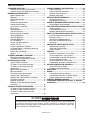
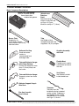
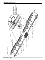
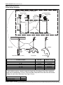
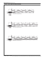
The Twin Fire Unitary Infrared Heater Submittal: TF-Series Job: Location: Engineer: Gas Specs: Date: QTY. MODEL NO. TF UNIT INPUT BTU/HR QTY. MODEL NO. TF UNIT INPUT BTU/HR QTY. MODEL NO. TF UNIT INPUT BTU/HR QTY. MODEL NO. TF UNIT INPUT BTU/HR TOTAL INPUT BTU/HR Important Before installation and operation of heating equipment, read and understand the Installation, Operation and Service Manual. Applications, engineering and detailed guidance on systems design, installation and product performance is available upon request. ® ROBERTS GORDON products are to be installed only in accordance with local laws, codes and regulations, and only by a contractor qualified in the installation and service of gas-fired heating equipment. Roberts-Gordon Roberts-Gordon Canada Inc. 1250 William Street P.O. Box 44 Buffalo, New York 14240-0044 Telephone: 716.852.4400 Fax: 716.852.0854 Toll Free: 800.828.7450 241 South Service Road West Grimsby, Ontario L3M 1Y7 Canada Telephone: 905.945.5403 Fax: 905.945.0511 www.rg-inc.com © Copyright 2001 Roberts-Gordon P/N190600NA 06/01 TABLE OF CONTENTS STANDARD PARTS LIST............................................. 1 Contents of TF-Series Burner Carton ..................... 1 Contents of Core and Extension Packages............. 1 GENERAL SPECIFICATIONS ...................................... 2 Material Specification .............................................. 2 Reflectors ................................................................ 2 Heater Specifications............................................... 2 Ignition ..................................................................... 2 Suspension Specifications....................................... 2 Controls Specifications ............................................ 2 Gas Pressure at Manifold: ....................................... 2 Dimensions: ............................................................. 2 Pipe Connection: ..................................................... 2 Gas Inlet Pressure:.................................................. 2 Electrical Rating (all Models): .................................. 2 Standard Reflector.................................................. 3 One Side Reflector .................................................. 3 Two Side Reflectors ................................................ 3 45° Tilt Reflector ...................................................... 4 U-Tube, Standard Reflector..................................... 4 U-Tube, Full 45° ...................................................... 4 U-Tube, Opposite 45° Reflector .............................. 5 2-Foot Deco Grille, 1-Foot Deco Grille and Protective Grille ....................................................... 5 Lower Clearance Shield* ......................................... 5 Venting .................................................................... 6 TF-SERIES ASSEMBLY OVERVIEW ........................... 7 Major Component Descriptions ............................... 7 TF-Series Linear Assembly Overview ................... 8 HEATER INSTALLATION............................................. 9 Critical Hanger Placement ....................................... 9 TF-Series Linear Layout Overview ......................... 10 TF-Series Linear Layout Overview (Continued).............................................................. 11 BBurner Tube Installation ........................................ 12 Burner Installation.................................................... 12 Tube Clamp Package Installation............................ 13 Coupling and Tube Assembly.................................. 13 Coupling and Tube Assembly (Continued).............. 14 Turbulator Installation .............................................. 15 Reflector Installation ................................................ 15 Reflector, U-Clip and Reflector Support Installation ............................................................... 16 OPTIONAL HEATER ACCESSORIES.......................... 17 TF-Series U-Tube Assembly Overview .................. 17 TF-Series U-Tube Layout Overviews ..................... 18 TF-Series U-Tube Layout Overviews (Continued).............................................................. 19 ELBOW PACKAGE CONFIGURATION........................20 Elbow Installation .....................................................20 Elbow Installation (continued) ..................................20 Reflector Joint Installation........................................20 Reflector Joint Detail................................................21 REFLECTOR SIDE EXTENSION ..................................22 Bracket Installation...................................................22 Side Reflector Installation ........................................22 LOWER CLEARANCE SHIELD INSTALLATION.........23 Shield Support Strap Assembly...............................23 TWO-FOOT DECORATIVE GRILLE INSTALLATION..23 Grille Installation ......................................................23 Frame Shield Installation .........................................24 Reflector Side Extension Installation ......................24 ONE-FOOT DECORATIVE GRILLE INSTALLATION..25 One-Foot Decorative Grille Bracket .........................25 Decorative Grille ......................................................25 Joint Piece and Reinforcement................................25 End Piece and Reflector End Cap ...........................26 90° Elbow.................................................................26 PROTECTIVE GRILLE INSTALLATION.......................27 Silicone Cap Installation...........................................27 Grille End Cap Installation .......................................27 Grille Installation ......................................................27 VENTING........................................................................28 Horizontal Ventilation 4" (10 cm) Pipe .....................28 Vertical Ventilation 4" (10 cm) Pipe..........................28 CFlexible Boot Installation (Single Vent)..................29 Common Sidewall Venting.......................................29 Vertical Ventilation 6" (15 cm) Pipe .........................30 Flexible Boot Installation (Common Vent)................30 OUTSIDE COMBUSTION AIR SUPPLY .......................31 Vertical Outside Air Supply .....................................31 Horizontal Outside Air Supplly.................................31 GAS PIPING...................................................................32 WIRING..........................................................................33 Line Voltage Thermostat Wiring...............................33 Low Voltage Thermostat and Relay Wiring..............34 Electrical Connection to the Burner .........................36 INTERNAL BURNER DIAGRAM...................................37 THE ROBERTS GORDON® VANTAGE ® TF LIMITED WARRANTY...................................................................38 © 2004 All rights reserved. No part of this work covered by the copyrights herein may be reproduced or copied in any form or by any means - graphic, electronic, or mechanical, including photocopying, recording, taping or information storage and retrieval systems - without the written permission of Roberts-Gordon. Printed in U.S.A. ROBERTS GOR DON® T F-SE RIE S SUB MI TT AL S HEE T STANDARD PARTS LIST Contents of TF-Series Burner Carton Part No. Description TF-120 TF-160 TF-200 TF-250 TF-300 TF-350 TF-380 090XXXXX TF Burner Assembly (Rate and Fuel Varies) 1 1 1 1 1 1 1 02568200 Gasket 1 1 1 1 1 1 1 190100NA Installation, Operation and Service Manual 1 1 1 1 1 1 1 94273914 Hex Head Bolts 5/16-18 Rolok 8 8 8 8 8 8 8 96411600 Split Lock washer 8 8 8 8 8 8 8 91412203 Flexible Gas Connector Assembly - 3/4" NPT 1 1 1 1 1 1 1 03051503 Turbulator Adapter 2 2 2 - - - - 03051504 Turbulator 2.5 ' (76 cm) Aluminized Steel 8 8 4 - - - - 91412800 Flexible Boot 2 2 2 2 2 2 2 91901300 Boot Clamp 4 4 4 4 4 4 4 09080000 Vent Sleeve 2 2 2 2 2 2 2 Contents of Core and Extension Packages Core Packages Extension Packages Part No. Description Aluminized with Aluminized with Aluminum Stainless Steel Reflector Reflector Hot Rolled with Aluminum Reflector Hot Rolled Aluminized Aluminized with with with Aluminum Aluminum Stainless Steel Reflector Reflector Reflector 20 ' 30' 40' 20' 30 ' 40' 20' 30 ' 40 ' 10' 20' 30 ' 40' 10' 20' 30 ' 40' 10' 20' 30 ' 40' 91409300 Tube, Hot Rolled Steel, 10 ' (3m) 1 2 3 - - - - - - 1 2 3 4 - - - - - - - - 91409408 Tube, HT Aluminized, 10' (3m) - - - 1 2 3 1 2 3 - - - - 1 2 3 4 1 2 3 4 03051101 Burner Tube, ALUMI-THERM® Steel, 10 ' (3m) 1 1 1 1 1 1 1 1 1 - - - - - - - - - - - - 01312700 Coupling Assembly 1 2 3 1 2 3 1 2 3 1 2 3 4 1 2 3 4 1 2 3 4 02750303 Standard Reflector, 8 ' (3.5m) 3 4 6 3 4 6 - - - 2 3 4 6 2 3 4 6 - - - - 02750800 End Cap 2 2 2 2 2 2 - - - - - - - - - - - - - - - 027503SS Stainless Steel Reflector, 8’ (3.5m) - - - - - - 3 4 6 - - - - - - - - 2 3 4 6 027508SS Stainless Steel End Cap - - - - - - 2 2 2 - - - - - - - - - - - - 03090100 Tube and Reflector Hanger 3 4 5 3 4 5 3 4 5 1 2 3 4 1 2 3 4 1 2 3 4 91907302 S-Hook 6 8 10 6 8 10 6 8 10 2 4 6 8 2 4 6 8 2 4 6 8 03050010 Reflector Support Package (Strap, Wire Form, Screws) 2 3 5 2 3 5 4 5 7 2 3 4 6 2 3 4 6 2 3 4 6 91107720 U-Clip Package 1 1 1 1 1 1 1 1 1 1 1 1 1 1 1 1 1 1 1 1 1 90502700 Vent Adapter (Not required for TF Models) 1 1 1 1 1 1 1 1 1 - - - - - - - - - - - - 01318901 Tube Clamp Package 1 1 1 1 1 1 2 2 2 - - - - - - - - - - - - CP40ALUMSS EXP10HRS EXP20HRS EXP30HRS EXP40HRS EXP10ALUM EXP20ALUM EXP30ALUM EXP40ALUM EXP10ALUMSS EXP20ALUMSS EXP30ALUMSS EXP40ALUMSS ( 9 m ) (1 2 m CP30ALUMSS (6 m ) CP20ALUMSS ( 9 m ) (1 2 m ( 3m ) CP40ALUM (6 m ) CP30ALUM ( 9 m ) ( 12 m ( 3m ) CP20ALUM (6 m ) CP40HRS (9 m ) ( 12 m ) ( 3m ) CP30HRS ( 9 m ) ( 12 m ) ( 6m ) CP20HRS ( 6 m ) ( 9m ) (1 2 m ) (6 m ) Part Number S, ENGI NEERING AND DETAI LED GUID ANCE ON SYSTEMS DESIGN, INSTALLATI ON AND PRODUCT PERFORMANCE IS AVAI LABLE UPON REQUEST. ROBERTS GORDON PRODUCTS ARE TO BE © 2004 Roberts-Gordon APPLICATION INSTALLED ONLY IN ACCORDANCE WI TH LOCAL LAWS, CODES AND REGULATIONS, AND ONLY BY A CONTRACTOR QUALI FIED I N THE I NSTALLATION AND SERVICE OF GAS-FIRED HEATING EQUI PMENT. ® ROBERTS GORDON ® T F-SE RIE S SU BMI TT AL S HEE T GENERAL SPECIFICATIONS Material Specification Reflectors Suspension Specifications Hang heater with materials with a minimum working load of 75 lbs (33 kg). Controls Specifications .024 Aluminum Heater Specifications Ignition Automatic direct spark ignition with safety shut-off. Time switches, thermostats, etc. can be wired into the electrical supply. External controls supplied as an optional extra. General Specifications for TF-Series heaters are as follows: Side View Length "A" Reflector 23.5" (60 cm) End View 13.75" (35 cm) 9.5" (24 cm) Length "A" Length “A” Each Side Recommended Minimum Mounting Height* Space Spot Heat Input Rate Model (BTUH X1000) Linear U-Tube Linear U-Tube TF-120 120 20' (6 m) 11'6" (4 m) 20' (6 m) 11'6" (4 m) 12' (4 m) 9' (3 m) TF-160 160 20' (6 m) 11'6" (4 m) 30' (9 m) 16'6" (5 m) 15' (5 m) 11' (3 m) TF-200 200 30' (9 m) 16'6" (5 m) 40' (12 m) 21'6" (7 m) 15' (5 m) 12' (4 m) TF-250 250 40' (12 m) 21’ 6" (7 m) 50' (15 m) 26'6" (8 m) 20' (6 m) 15' (5 m) TF-300 300 50' (15 m) 26'6" (8 m) 60' (18 m) 31'6" (10 m) 20' (6 m) 20' (6 m) TF-350 350 50' (15 m) 26'6" (8 m) 70' (21 m) 36'6" (11 m) 25' (8 m) 23' (7 m) TF-380 380 60' (18 m) 31'6" (10 m) 80' (24 m) 41'6" (13 m) 25' (8 m) 23' (7 m) Minimum Maximum Pipe Connection: Gas Pressure at Manifold: 3/4" NPT Natural Gas: 3.5" w.c. Gas Inlet Pressure: LP Gas: 10.5" w.c. Natural Gas: 5.0" w.c. Minimum Dimensions: 16.0" w.c. Maximum Vent Connection Size: LP Gas: 12.0" w.c. Minimum 4" (10 cm) or 6" (15 cm) 16.0" w.c. Maximum Outside Air Connection Size: Electrical Rating (all Models): 4" (10 cm) or 6" (15 cm) 120V - 60 Hz., 1.0 Amp Refer to figure above for dimensional information. CATIONS, ENGIN EERING AND DETAI LED GUIDANCE ON SYSTEMS DESI GN, I NSTALLATION AND PRODUCT PERFORMANCE I S AVAILABLE UPO N REQUEST. ROBERTS GO RDON PRODUCTS ARE TO BE © 2004 Roberts-Gordon APPLI INSTALLED ONLY I N ACCOR DANCE WITH LOCAL LAW S, CODES AND REGULATIONS, AND ONLY BY A CONTRACTO R QUALI FIED IN THE INSTALLATION AND SERVICE OF GAS-F IRED HEATING EQUIPMEN T. ® ROBERTS GOR DON® T F-SE RIE S SUB MI TT AL S HEE T NOTE: 1. All dimensions are from the surfaces of all tubes, couplings and elbows. 2. Clearances B, C and D can be reduced by 50% after 25' (7.5 m) of tubing downstream from where the burner and burner tube connect. Standard Reflector A B C D Model A (inches) B C TF-120 6 35 63 35 16 89 161 89 TF-160 6 38 66 38 16 97 168 97 TF-200 6 40 71 40 16 102 181 102 TF-250 6 46 77 46 16 117 196 117 TF-300 6 50 80 50 16 127 204 127 TF-350 8 52 82 52 21 133 209 133 TF-380 8 52 82 52 21 133 209 133 Model A (inches) B C D A TF-120 6 9 63 47 16 23 161 120 TF-160 6 9 70 54 16 23 178 138 TF-200 6 9 77 59 16 23 196 150 TF-250 6 9 83 65 16 23 211 166 TF-300 6 9 86 69 16 23 219 176 TF-350 8 9 88 73 21 23 224 186 TF-380 8 9 88 73 21 23 224 186 Model A (inches) B C D A TF-120 6 23 66 23 16 59 168 59 TF-160 6 25 72 25 16 64 183 64 TF-200 6 27 78 27 16 69 199 69 TF-250 6 32 84 32 16 82 214 82 TF-300 6 35 88 35 16 89 224 89 TF-350 8 40 91 40 21 102 232 102 TF-380 8 40 91 40 21 102 232 102 D A (centimeters) B C D One Side Reflector A B C D (centimeters) B C D Two Side Reflectors A C B D (centimeters) B C D S, ENGI NEERING AND DETAI LED GUID ANCE ON SYSTEMS DESIGN, INSTALLATI ON AND PRODUCT PERFORMANCE IS AVAI LABLE UPON REQUEST. ROBERTS GORDON PRODUCTS ARE TO BE © 2004 Roberts-Gordon APPLICATION INSTALLED ONLY IN ACCORDANCE WI TH LOCAL LAWS, CODES AND REGULATIONS, AND ONLY BY A CONTRACTOR QUALI FIED I N THE I NSTALLATION AND SERVICE OF GAS-FIRED HEATING EQUI PMENT. ® ROBERTS GORDON ® T F-SE RIE S SU BMI TT AL S HEE T NOTE: 1. All dimensions are from the surfaces of all tubes, couplings and elbows. 2. Clearances B, C and D can be reduced by 50% after 25' (7.5 m) of tubing downstream from where the burner and burner tube connect. 45 ° Tilt Reflector A C B D Model A (inches) B C TF-120 8 8 60 54 21 21 153 138 TF-160 8 8 66 60 21 21 168 153 TF-200 10 8 74 64 26 21 188 163 TF-250 10 8 78 69 26 21 199 176 TF-300 12 8 84 74 31 21 214 188 TF-350 12 8 85 79 31 21 216 201 TF-380 12 8 85 79 31 21 216 201 Model A (inches) B C D A TF-120 6 35 63 30 16 89 161 77 TF-160 6 38 69 37 16 97 176 94 TF-200 6 40 76 39 16 102 194 100 TF-250 6 46 79 43 16 117 201 110 TF-300 6 50 84 47 16 127 214 120 TF-350 8 54 87 51 21 138 221 130 TF-380 8 54 87 51 21 138 221 130 Model A (inches) B C D A TF-120 8 8 60 42 21 21 153 107 TF-160 8 8 66 46 21 21 168 117 TF-200 8 8 74 52 21 21 188 133 TF-250 8 8 78 61 21 21 199 155 TF-300 8 8 84 66 21 21 214 168 TF-350 8 8 85 70 21 21 216 178 TF-380 8 8 85 70 21 21 216 178 D A (centimeters) B C D U-Tube, Standard Reflector A C B D (centimeters) B C D U-Tube, Full 45° A B D C (centimeters) B C D CATIONS, ENGIN EERING AND DETAI LED GUIDANCE ON SYSTEMS DESI GN, I NSTALLATION AND PRODUCT PERFORMANCE I S AVAILABLE UPO N REQUEST. ROBERTS GO RDON PRODUCTS ARE TO BE © 2004 Roberts-Gordon APPLI INSTALLED ONLY I N ACCOR DANCE WITH LOCAL LAW S, CODES AND REGULATIONS, AND ONLY BY A CONTRACTO R QUALI FIED IN THE INSTALLATION AND SERVICE OF GAS-F IRED HEATING EQUIPMEN T. ® ROBERTS GOR DON® T F-SE RIE S SUB MI TT AL S HEE T NOTE: 1. All dimensions are from the surfaces of all tubes, couplings and elbows. 2. Clearances B, C and D can be reduced by 50% after 25' (7.5 m) of tubing downstream from where the burner and burner tube connect. U-Tube, Opposite 45° Reflector A B D C Model A (inches) B C TF-120 8 54 60 22 21 138 153 56 TF-160 8 60 66 22 21 153 168 56 TF-200 10 64 74 22 26 163 188 56 TF-250 10 70 78 22 26 178 199 56 TF-300 12 74 84 22 31 188 214 56 TF-350 12 76 85 22 31 194 216 56 TF-380 12 76 85 22 31 194 216 56 2-Foot Deco Grille, 1-Foot Deco Grille and Protective Grille (inches) Model A B C A C B D D A D A (centimeters) B C D (centimeters) B C D TF-120 6 35 63 35 16 89 161 89 TF-160 6 38 66 38 16 97 168 97 TF-200 6 40 71 40 16 102 181 102 TF-250 6 46 77 46 16 117 196 117 TF-300 6 50 80 50 16 127 204 127 TF-350 8 52 82 52 21 133 209 133 TF-380 8 52 82 52 21 133 209 133 Model A (inches) B C D A TF-120 6 39 33 39 16 100 84 100 TF-160 6 40 38 40 16 102 97 102 TF-200 6 50 44 50 16 127 112 127 TF-250 6 54 48 54 16 138 122 138 TF-300 6 55 50 55 16 140 127 140 Lower Clearance Shield* A C B D TF-350** Unapproved (centimeters) B C D Unapproved TF-380** Unapproved Unapproved *When installed in the first 20’ (6 m) on each side of the burner. **Roberts-Gordon prohibits the installation of this heater for all unapproved applications. S, ENGI NEERING AND DETAI LED GUID ANCE ON SYSTEMS DESIGN, INSTALLATI ON AND PRODUCT PERFORMANCE IS AVAI LABLE UPON REQUEST. ROBERTS GORDON PRODUCTS ARE TO BE © 2004 Roberts-Gordon APPLICATION INSTALLED ONLY IN ACCORDANCE WI TH LOCAL LAWS, CODES AND REGULATIONS, AND ONLY BY A CONTRACTOR QUALI FIED I N THE I NSTALLATION AND SERVICE OF GAS-FIRED HEATING EQUI PMENT. ® ROBERTS GORDON ® T F-SE RIE S SU BMI TT AL S HEE T NOTE: 1. All dimensions are from the surfaces of all tubes, couplings and elbows. 2. Clearances B, C and D can be reduced by 50% after 25' (7.5 m) of tubing downstream from where the burner and burner tube connect. Venting A Unvented Infrared Tubes Vented E Vent Pipes F Model A (inches) E TF-120 14 18 18 36 46 46 TF-160 20 24 18 51 61 46 TF-200 20 24 18 51 61 46 TF-250 20 24 18 51 61 46 TF-300 20 30 18 51 77 46 TF-350 20 30 18 51 77 46 TF-380 20 30 18 51 77 46 F A (centimeters) E F CATIONS, ENGIN EERING AND DETAI LED GUIDANCE ON SYSTEMS DESI GN, I NSTALLATION AND PRODUCT PERFORMANCE I S AVAILABLE UPO N REQUEST. ROBERTS GO RDON PRODUCTS ARE TO BE © 2004 Roberts-Gordon APPLI INSTALLED ONLY I N ACCOR DANCE WITH LOCAL LAW S, CODES AND REGULATIONS, AND ONLY BY A CONTRACTO R QUALI FIED IN THE INSTALLATION AND SERVICE OF GAS-F IRED HEATING EQUIPMEN T. ® ROBERTS GOR DON® T F-SE RIE S SUB MI TT AL S HEE T TF-SERIES ASSEMBLY OVERVIEW Major Component Descriptions Burner with Tube Gasket Must be installed with the flame observation window facing down. Burner Tube Supplied in 10' (3 m) lengths. Burner tube is always the first tube after the burner. Reflector End Cap Punch out center section to accommodate heat exchanger tube. Tube and Reflector Hanger with Clamp Package Position this hanger no more than 4” (10 cm) away from the burner. Tube and Reflector Hanger Suspend system from these hangers. Reflector (Aluminum or Stainless Steel) Alternate overlap as shown on overview and on Page 10, Figure . Minimum overlap is 7” (18 cm). Tube Hot Rolled or Heat Treated Aluminized Tube Supplied in 10’ (3 m) lengths. Coupling Assembly with Lock Flexible Boot Flexible boot is used to connect the last tube to the vent. Vent Sleeve Vent Sleeve installed inside flexible boot. Reflector Support Strap & Wire Form Flex Gas Line with Shut Off Cock Turbulator Turbulator must be installed in the last standard section of tube. Turbulator is not required on the TF-250/ 300/350/380. For installation see Page 15, Section . S, ENGI NEERING AND DETAI LED GUID ANCE ON SYSTEMS DESIGN, INSTALLATI ON AND PRODUCT PERFORMANCE IS AVAI LABLE UPON REQUEST. ROBERTS GORDON PRODUCTS ARE TO BE © 2004 Roberts-Gordon APPLICATION INSTALLED ONLY IN ACCORDANCE WI TH LOCAL LAWS, CODES AND REGULATIONS, AND ONLY BY A CONTRACTOR QUALI FIED I N THE I NSTALLATION AND SERVICE OF GAS-FIRED HEATING EQUI PMENT. ® ROBERTS GORDON ® T F-SE RIE S SU BMI TT AL S HEE T Flexible Boot Turbulator Reflector Support Tube and Reflector Hanger Burner Tube Clamp Package Burner Tube Coupling Tube Reflector End Cap Reflector Burner Tube Tube Clamp Flat Washer Nut (Torque 120 in/lb 13.56 Nm) Bolt U-Clips For shorter than minimum suspension lengths, tube clamps must be used at the two farthest hangers on each side of the burner. TF-Series Linear Assembly Overview CATIONS, ENGIN EERING AND DETAI LED GUIDANCE ON SYSTEMS DESI GN, I NSTALLATION AND PRODUCT PERFORMANCE I S AVAILABLE UPO N REQUEST. ROBERTS GO RDON PRODUCTS ARE TO BE © 2004 Roberts-Gordon APPLI INSTALLED ONLY I N ACCOR DANCE WITH LOCAL LAW S, CODES AND REGULATIONS, AND ONLY BY A CONTRACTO R QUALI FIED IN THE INSTALLATION AND SERVICE OF GAS-F IRED HEATING EQUIPMEN T. ® ROBERTS GOR DON® T F-SE RIE S SUB MI TT AL S HEE T HEATER INSTALLATION Critical Hanger Placement Typical Suspension Details Beam Clamp Anchor Screw Hook (3/8") 24" min.* (61 cm) Rod (3/8") Chain size 3/16" minimum Concrete Beam Wood Beam Locknut Washers X* S Hooks Turnbuckle Not Included * Allows for thermal expansion of system S Hooks Hanger Side View Hanger Reflector Must Be Within 4" (10 cm) Front View Total Str aight Length (both sides) or Length from U-Tube to U-Tube in a Double "U" Layout 0’ - 50’ 51’ - 60’ 61’ - 80’ 81’ - 100’ 101’ - 120’ 121’ - 140’ 141’ - 160’ 45° Angle Typical Expansion Each Side ±1” (3 cm) ±2” (5 cm) ±3” (8 cm) ±4” (10 cm) ±5” (13 cm) ±6” (15 cm) ±7” (18 cm) Minimum “X” Length 12” (31 cm) 18” (46 cm) 24” (61 cm) 30" (76 cm) 36" (91 cm) 42" (107 cm) 48" (122 cm) If the installation requires a shorter suspension length than the minimum listed, the suspension length may be reduced by 6" (16 cm). In this case tube clamps MUST be used at the two farthest hangers on each side of the burner. See Page 8, Figure . Description S-Hook Tube/Reflector Hanger Par t Number 91907302 03090100 S, ENGI NEERING AND DETAI LED GUID ANCE ON SYSTEMS DESIGN, INSTALLATI ON AND PRODUCT PERFORMANCE IS AVAI LABLE UPON REQUEST. ROBERTS GORDON PRODUCTS ARE TO BE © 2004 Roberts-Gordon APPLICATION INSTALLED ONLY IN ACCORDANCE WI TH LOCAL LAWS, CODES AND REGULATIONS, AND ONLY BY A CONTRACTOR QUALI FIED I N THE I NSTALLATION AND SERVICE OF GAS-FIRED HEATING EQUI PMENT. ® ROBERTS GORDON ® T F-SE RIE S SU BMI TT AL S HEE T TF-Series Linear Layout Overview Linear layouts showing one side. Use same measurements for the other side. LEGEND g Burner Reflector b c d e f Tube TF-120 TF-160 Tube/Reflector Hanger Coupling Assembly g a = 14" (36 cm) reflector width (not shown) b = 2" (5 cm) end cap to burner 20' (6m) Tube Length (each side) b c d e e f c = 2" (5 cm) end cap to hanger TF-160 TF-200 d = 7'6" (229 cm) distance first hanger e = 10' (305 cm) distance between hangers g 30' (9m) Tube Length (each side) b c d e e e f = 9.5" (24 cm) burner height g = 23.5" (60 cm) burner length f g b c TF-200 TF-250 40' (12m) Tube Length (each side) d e TF-250 TF-300 TF-350 50' (15m) Tube Length (each side) e e e f CATIONS, ENGIN EERING AND DETAI LED GUIDANCE ON SYSTEMS DESI GN, I NSTALLATION AND PRODUCT PERFORMANCE I S AVAILABLE UPO N REQUEST. ROBERTS GO RDON PRODUCTS ARE TO BE © 2004 Roberts-Gordon APPLI INSTALLED ONLY I N ACCOR DANCE WITH LOCAL LAW S, CODES AND REGULATIONS, AND ONLY BY A CONTRACTO R QUALI FIED IN THE INSTALLATION AND SERVICE OF GAS-F IRED HEATING EQUIPMEN T. ® ROBERTS GOR DON® T F-SE RIE S SUB MI TT AL S HEE T TF-Series Linear Layout Overview (Continued) g b c d e e e e e e e e e e e e e f TF-300 TF-350 TF-380 g 60' (18m) Tube Length (each side) b c d e e b f TF-350 TF-380 g 70' (21m) Tube Length (each side) b c d e e b f TF-380 80' (24m) Tube Length (each side) S, ENGI NEERING AND DETAI LED GUID ANCE ON SYSTEMS DESIGN, INSTALLATI ON AND PRODUCT PERFORMANCE IS AVAI LABLE UPON REQUEST. ROBERTS GORDON PRODUCTS ARE TO BE © 2004 Roberts-Gordon APPLICATION INSTALLED ONLY IN ACCORDANCE WI TH LOCAL LAWS, CODES AND REGULATIONS, AND ONLY BY A CONTRACTOR QUALI FIED I N THE I NSTALLATION AND SERVICE OF GAS-FIRED HEATING EQUI PMENT. ® ROBERTS GORDON ® T F-SE RIE S SU BMI TT AL S HEE T BBurner Tube Installation NOTE: Tubing requires a downward slope of 1/2" (13 mm) per 20' (6 m) away from burner. Offset mounting hole must be to the top Weld Seam must be to the bottom of the tube. 7' 6" ± 1' (229 cm ± 25 cm) S Hook 29"± 2" (73 cm ± 5 cm) Description Burner Tube S-Hook Tube/Reflector Hanger Par t Number 03051XXX 91907302 03090100 Burner Tube Hanger Burner Installation Bolt Lock Washer Gasket Burner Description Bolt Lock Washer Gasket Burner Part Number 94273914 96411600 02568200 090XXXXX CATIONS, ENGIN EERING AND DETAI LED GUIDANCE ON SYSTEMS DESI GN, I NSTALLATION AND PRODUCT PERFORMANCE I S AVAILABLE UPO N REQUEST. ROBERTS GO RDON PRODUCTS ARE TO BE © 2004 Roberts-Gordon APPLI INSTALLED ONLY I N ACCOR DANCE WITH LOCAL LAW S, CODES AND REGULATIONS, AND ONLY BY A CONTRACTO R QUALI FIED IN THE INSTALLATION AND SERVICE OF GAS-F IRED HEATING EQUIPMEN T. ® ROBERTS GOR DON® T F-SE RIE S SUB MI TT AL S HEE T Tube Clamp Package Installation Tube Clamp Bolt Flat Washer Nut (Torque 120 in/lb 13.56 Nm) Description Tube Clamp Package Tube Clamp Bolt Flat Washer Nut Part Number 01318901 01396801 97113940 95211600 92113900 Coupling and Tube Assembly coupling A Close with tab Slide bar/Coupling Lock B Start onto coupling Tab Slide Bar/Coupling Lock Wide end Coupling Open 3" (8 cm) to 4" (10 cm) Closed C Insert tubes into coupling D Tighten coupling to join tubes Slide Bar/Coupling Lock Coupling Orient coupling so that the impact block is in the 2:00 or 10:00 oclock positions Tube Tube Tube Descr iption Coupling Slide bar/Coupling Lock Tube Part Number 01329600 01329700 91409XXX S, ENGI NEERING AND DETAI LED GUID ANCE ON SYSTEMS DESIGN, INSTALLATI ON AND PRODUCT PERFORMANCE IS AVAI LABLE UPON REQUEST. ROBERTS GORDON PRODUCTS ARE TO BE © 2004 Roberts-Gordon APPLICATION INSTALLED ONLY IN ACCORDANCE WI TH LOCAL LAWS, CODES AND REGULATIONS, AND ONLY BY A CONTRACTOR QUALI FIED I N THE I NSTALLATION AND SERVICE OF GAS-FIRED HEATING EQUI PMENT. ® ROBERTS GORDON ® T F-SE RIE S SU BMI TT AL S HEE T Coupling and Tube Assembly (Continued) Tighten slide bar as shown below Drive Slide Bar until tight. End of Slide Bar should be within tolerance listed below. ± 2" (5 cm) Correct Slide Bar dimensions Incorrect Slide Bar position • Repeat A - D until all tubes are assembled. Coupling and Tube Assembly (Continued) Model TF-120 TF-160 TF-200 TF-250 TF-300 TF-350 TF-380 Tube Length Per Side Minimum Maximum 20’ (6 m) 20’ (6 m) 20’ (6 m) 30’ (9 m) 30’ (9 m) 40’ (12 m) 40’ (12 m) 50’ (15 m) 50’ (15 m) 60’ (18 m) 50’ (15 m) 70’ (21 m) 60’ (18 m) 80’ (24 m) See recommended venting lengths on Page 28, Section , when using maximum tube lengths. 7' 6" ± 1' (229 cm ± 25 cm) 10' Typ. ± 1' (254 cm Typ ± 25 cm) CATIONS, ENGIN EERING AND DETAI LED GUIDANCE ON SYSTEMS DESI GN, I NSTALLATION AND PRODUCT PERFORMANCE I S AVAILABLE UPO N REQUEST. ROBERTS GO RDON PRODUCTS ARE TO BE © 2004 Roberts-Gordon APPLI INSTALLED ONLY I N ACCOR DANCE WITH LOCAL LAW S, CODES AND REGULATIONS, AND ONLY BY A CONTRACTO R QUALI FIED IN THE INSTALLATION AND SERVICE OF GAS-F IRED HEATING EQUIPMEN T. ® ROBERTS GOR DON® T F-SE RIE S SUB MI TT AL S HEE T Turbulator Installation Turbulator must be installed in the last standard section of tube. T w i st Turbulator 2.5' Section Turbulator Adapter Tab Pull String Description Turbulator Section 1 Turbulator Section 2 Tube Part Number 03051503 03051504 91409XXX Fold tab around outside of tube nearest to the vent to hold turbulator in place. Where a vent sleeve is used, do not fold tab. Reflector Installation NOTE: All tube surfaces must be covered by a reflector, except for a U-Tube. Burner Hanger Burner Tube Reflector Description Tube/Reflector Hanger Burner Tube Reflector Part Num ber 03090100 03051XXX 02750303 S, ENGI NEERING AND DETAI LED GUID ANCE ON SYSTEMS DESIGN, INSTALLATI ON AND PRODUCT PERFORMANCE IS AVAI LABLE UPON REQUEST. ROBERTS GORDON PRODUCTS ARE TO BE © 2004 Roberts-Gordon APPLICATION INSTALLED ONLY IN ACCORDANCE WI TH LOCAL LAWS, CODES AND REGULATIONS, AND ONLY BY A CONTRACTOR QUALI FIED I N THE I NSTALLATION AND SERVICE OF GAS-FIRED HEATING EQUI PMENT. ® ROBERTS GORDON ® T F-SE RIE S SU BMI TT AL S HEE T Reflector, U-Clip and Reflector Support Installation The pictorial drawings of the heater construction in this Section are schematic only and provide a general guideline of where hangers, reflector supports and U-clips are to be installed. To ensure proper expansion and contraction movement of the reflectors, a combination of U-clips and reflector supports are used. The positioning of reflector supports and U-clips depend on the individual installation. The following rules must be observed. 1. The first reflector after the burner must be affixed in the middle of the reflector with a reflector support and tight screws. Tight Sheet Metal Screw Wire Form Reflector End Cap First Reflector Reflector Support Strap U-Clips Overlap must be a minimum of 6" (16 cm) Option B Slip Overlap 6" (16 cm) 2. The overlap at the first and second reflector is a slip overlap. Thereafter, every third reflector joint is a slip overlap. A slip overlap is achieved by either: a.) both reflectors lay inside a hanger. (no reflector support needed). b.) using a reflector support with loose screws at the reflector overlap. Loose screws loosened 1/16" (2 mm) to allow slippage. Option A Slip Overlap Option A Non-Slip Overlap 3. The remaining reflector overlaps require a non-slip overlap connection. To affix the reflectors together in a non-slip overlap either: a.) use reflector support and tight screws. b.) if both reflectors lay inside a hanger, u-clips or sheet metal screws may be used. This section of three reflectors joined together must be affixed to the tube with at least one reflector support with tight screws. Description Reflector Suppor t Package Wire Form Reflector Support Strap Screw #8 x 3/4 U-Clip Package Reflector End Cap Part Number 03050010 91908004 03050000 94320812 91107720 027508XX Reflector Reflector Support Reflector Tight screws Option B Non-Slip Overlap U-Clip (2 clips per non-slip overlap inside a hanger) CATIONS, ENGIN EERING AND DETAI LED GUIDANCE ON SYSTEMS DESI GN, I NSTALLATION AND PRODUCT PERFORMANCE I S AVAILABLE UPO N REQUEST. ROBERTS GO RDON PRODUCTS ARE TO BE © 2004 Roberts-Gordon APPLI INSTALLED ONLY I N ACCOR DANCE WITH LOCAL LAW S, CODES AND REGULATIONS, AND ONLY BY A CONTRACTO R QUALI FIED IN THE INSTALLATION AND SERVICE OF GAS-F IRED HEATING EQUIPMEN T. ® ROBERTS GOR DON® T F-SE RIE S SUB MI TT AL S HEE T OPTIONAL HEATER ACCESSORIES TF-Series U-Tube Assembly Overview Reflector End Cap Reflector Turbulator Coupling Description U-Tube Package 180° U-Tube Tube and Reflector Hanger Coupling Reflector End Cap (2) U-Tube Support Bracket 4" (10 cm) U-Bolts (2) Reflector Suppor t Set S-Hook Hex Nut Lock Washer Part Number 03011000 01335901 03090100 01312700 02750800 03020501 90912500 03050010 91907302 92113000 96411500 Burner Tube U-Tube Support Bracket Assembly U-Clips Tube Clamp Package Burner U-Tube, Standard 1 2 Tube U-Tube, Full 45° 1 2 180° U-Tube 18" (45.7 cm) Center to Center Reflector Support Tight U-Bolt 4" (10 cm) U-Bolt, secured to Burner Tube with 1/4" (6 mm) Lockwashers and 1/4-20 Hex Nuts 2 Loose U-Bolt 4" (10 cm) U-Bolt, secured to Bracket with 1/4" (6 mm) Lockwashers and 1/4-20 Hex Nuts on top and bottom to allow for tube expansion and contraction 1 U-Tube, Opposite 45° 1 2 U-Bolt Nut Lock Washer Lock Washer Nut S, ENGI NEERING AND DETAI LED GUID ANCE ON SYSTEMS DESIGN, INSTALLATI ON AND PRODUCT PERFORMANCE IS AVAI LABLE UPON REQUEST. ROBERTS GORDON PRODUCTS ARE TO BE © 2004 Roberts-Gordon APPLICATION INSTALLED ONLY IN ACCORDANCE WI TH LOCAL LAWS, CODES AND REGULATIONS, AND ONLY BY A CONTRACTOR QUALI FIED I N THE I NSTALLATION AND SERVICE OF GAS-FIRED HEATING EQUI PMENT. ® ROBERTS GORDON ® T F-SE RIE S SU BMI TT AL S HEE T TF-Series U-Tube Layout Overviews U-tube layouts showing one side. Use same measurements for the other side. LEGEND g Burner b c e Reflector Tube 10' (3m) h TF-120 TF-160 Tube 5' (1.5m)** Tube/Reflector Hanger g Coupling Assembly 20' (6m) Tube Length* (each side) b c d f U-Tube a = 14" (36 cm) reflector width (not shown) h b = 2" (5 cm) end cap to burner TF-160 TF-200 c = 2" (5 cm) end cap to hanger d = 7'6" (229 cm) distance first hanger g 30' (9m) Tube Length**(each side) b c d e e = 10' (305 cm) distance between hangers f = 5' (153 cm) distance between last full tube hanger and half tube hanger h TF-200 TF-250 g = 17.5" (44 cm) burner length h = 9.5" (24 cm) burner height g 40' (12m) Tube Length (each side) b c d e f *Requires the last reflector before the U-Tube to be cut in half for use on both sides. **Requires the last tube before the U-Tube to be cut in half for use on both sides. h TF-250 TF-300 TF-350 50' (15m) Tube Length* ** (each side) CATIONS, ENGIN EERING AND DETAI LED GUIDANCE ON SYSTEMS DESI GN, I NSTALLATION AND PRODUCT PERFORMANCE I S AVAILABLE UPO N REQUEST. ROBERTS GO RDON PRODUCTS ARE TO BE © 2004 Roberts-Gordon APPLI INSTALLED ONLY I N ACCOR DANCE WITH LOCAL LAW S, CODES AND REGULATIONS, AND ONLY BY A CONTRACTO R QUALI FIED IN THE INSTALLATION AND SERVICE OF GAS-F IRED HEATING EQUIPMEN T. ® ROBERTS GOR DON® T F-SE RIE S SUB MI TT AL S HEE T TF-Series U-Tube Layout Overviews (Continued) g b c d e e h TF-300 TF-350 g 60' (18m) Tube Length (each side) b c d e e f h TF-350 TF-380 g 70' (21m) Tube Length** (each side) b c d e e e h TF-380 80' (24m) Tube Length** (each side) S, ENGI NEERING AND DETAI LED GUID ANCE ON SYSTEMS DESIGN, INSTALLATI ON AND PRODUCT PERFORMANCE IS AVAI LABLE UPON REQUEST. ROBERTS GORDON PRODUCTS ARE TO BE © 2004 Roberts-Gordon APPLICATION INSTALLED ONLY IN ACCORDANCE WI TH LOCAL LAWS, CODES AND REGULATIONS, AND ONLY BY A CONTRACTOR QUALI FIED I N THE I NSTALLATION AND SERVICE OF GAS-FIRED HEATING EQUI PMENT. ® ROBERTS GORDON ® T F-SE RIE S SU BMI TT AL S HEE T ELBOW PACKAGE CONFIGURATION Elbow Installation Tube Coupling Description Elbow Package 90° Elbow Coupling Reflector End Cap Reflector Joint Piece U-Clip Package Part Number 02718702 01335801 01312700 02750800 02750900 91107720 90° Elbow Elbow Installation (continued) Tube Coupling Reflector Joint Installation Reflector Reflector Joint Flatten Edge Scribe Contour 1" (2.5 cm) maximum Reflector Joi29 CATIONS, ENGIN EERING AND DETAI LED GUIDANCE ON SYSTEMS DESI GN, I NSTALLATION AND PRODUCT PERFORMANCE I S AVAILABLE UPO N REQUEST. ROBERTS GO RDON PRODUCTS ARE TO BE © 2004 Roberts-Gordon APPLI INSTALLED ONLY I N ACCOR DANCE WITH LOCAL LAW S, CODES AND REGULATIONS, AND ONLY BY A CONTRACTO R QUALI FIED IN THE INSTALLATION AND SERVICE OF GAS-F IRED HEATING EQUIPMEN T. ® ROBERTS GOR DON® T F-SE RIE S SUB MI TT AL S HEE T nt Installation Cut away contour with tin snips. Punch/Drill six 3/32" (2 mm) holes Reflector Joint Detail Install Reflector End Cap Attach Reflector Joint with six #8 sheet metal screws Reflector Joint Detail Reflector Reflector Joint S, ENGI NEERING AND DETAI LED GUID ANCE ON SYSTEMS DESIGN, INSTALLATI ON AND PRODUCT PERFORMANCE IS AVAI LABLE UPON REQUEST. ROBERTS GORDON PRODUCTS ARE TO BE © 2004 Roberts-Gordon APPLICATION INSTALLED ONLY IN ACCORDANCE WI TH LOCAL LAWS, CODES AND REGULATIONS, AND ONLY BY A CONTRACTOR QUALI FIED I N THE I NSTALLATION AND SERVICE OF GAS-FIRED HEATING EQUI PMENT. ® ROBERTS GORDON ® T F-SE RIE S SU BMI TT AL S HEE T REFLECTOR SIDE EXTENSION Bracket Installation Tube Reflector Tube and Reflector Hanger Reflector Support Reflector Side Extension Bracket (2 per reflector) Use additional supports in high air movement applications. Description Reflector Side Extension Package Reflector Side Extension Retainer Clips Sheet Metal Screws Order Separately Reflector Side Extension Par t Number 02712700 01368000 02751200 94118106 01329910 Side Reflector Installation #8 x 3/8" Sheet Metal Screw Retainer Clip (2 per side) Reflector Side Extension CATIONS, ENGIN EERING AND DETAI LED GUIDANCE ON SYSTEMS DESI GN, I NSTALLATION AND PRODUCT PERFORMANCE I S AVAILABLE UPO N REQUEST. ROBERTS GO RDON PRODUCTS ARE TO BE © 2004 Roberts-Gordon APPLI INSTALLED ONLY I N ACCOR DANCE WITH LOCAL LAW S, CODES AND REGULATIONS, AND ONLY BY A CONTRACTO R QUALI FIED IN THE INSTALLATION AND SERVICE OF GAS-F IRED HEATING EQUIPMEN T. ® ROBERTS GOR DON® T F-SE RIE S SUB MI TT AL S HEE T LOWER CLEARANCE SHIELD INSTALLATION Shield Support Strap Assembly Reflector 17.1" (434 mm) 12" (300 mm) Align pilot holes Lower Clearance Shield Locknuts Washers Descr iption Part Number Lower Clearance Shield Package 01397501 Shield Support Strap 01397500 Lower Clearance Shield 02793000 Locknut #8 92311400 Flat Washer #8 95310800 Screw #8 x 3/8" 93511406 Screws TWO-FOOT DECORATIVE GRILLE INSTALLATION Grille Installation Tube and Reflector Hanger Reflector Tube 61 x 122 cm Aluminium Grille Suspended Ceiling Frame Description Aluminium Grille 2’ x 4’ Part Number 91407000 S, ENGI NEERING AND DETAI LED GUID ANCE ON SYSTEMS DESIGN, INSTALLATI ON AND PRODUCT PERFORMANCE IS AVAI LABLE UPON REQUEST. ROBERTS GORDON PRODUCTS ARE TO BE © 2004 Roberts-Gordon APPLICATION INSTALLED ONLY IN ACCORDANCE WI TH LOCAL LAWS, CODES AND REGULATIONS, AND ONLY BY A CONTRACTOR QUALI FIED I N THE I NSTALLATION AND SERVICE OF GAS-FIRED HEATING EQUI PMENT. ® ROBERTS GORDON ® T F-SE RIE S SU BMI TT AL S HEE T Frame Shield Installation Shield Descr iption Deco Grille Shield Part Number 01365900 Reflector Side Extension Installation NOTE: If the Decorative Grille system is to be installed in an area with considerable air movement, it is recommended that one #8 x 3/8 (3.9 x 9.5mm) sheet metal screw be installed per reflector extension to prevent it from blowing over. Cut Relief Notches for Tube and Reflector Hangers Insert Screw here A Reflector Side Extension Distance "A" Minimum Maximum 2" (4 cm) 6" (15 cm) 6" (15 cm) 10" (26 cm) 10" (26 cm) 14" (37 cm) Extension Par t No. Width 01370408 8" (20 cm) 01370412 12" (30 cm) 01370416 16" (40 cm) Description Reflector Side Extension Part Number 01370412 CATIONS, ENGIN EERING AND DETAI LED GUIDANCE ON SYSTEMS DESI GN, I NSTALLATION AND PRODUCT PERFORMANCE I S AVAILABLE UPO N REQUEST. ROBERTS GO RDON PRODUCTS ARE TO BE © 2004 Roberts-Gordon APPLI INSTALLED ONLY I N ACCOR DANCE WITH LOCAL LAW S, CODES AND REGULATIONS, AND ONLY BY A CONTRACTO R QUALI FIED IN THE INSTALLATION AND SERVICE OF GAS-F IRED HEATING EQUIPMEN T. ® ROBERTS GOR DON® T F-SE RIE S SUB MI TT AL S HEE T ONE-FOOT DECORATIVE GRILLE INSTALLATION One-Foot Decorative Grille Bracket #8 Sheet Metal Screws Decorative Grille Bracket Description Bracket Part Number 01363003 In order to maintain reflector shape, do not fasten brackets together. Do not fasten bracket to adjoining reflectors. Maintain same slipjoint position as reflectors. Cut relief notches for supports and hangers. 2" Minimum Bracket Overlap Decorative Grille Spread apart brackets and install Decorative Grille. Description Decorative Grille 8’ x 1’ Part Number 91406700 Joint Piece and Reinforcement Joint Piece Slip joint piece into support bracket and fasten to bracket on one side of the joint only. Description Joint Piece Reinforcement Par t Number 01365903 01365902 Reinforcement #8 Sheet Metal Screws Joint Piece S, ENGI NEERING AND DETAI LED GUID ANCE ON SYSTEMS DESIGN, INSTALLATI ON AND PRODUCT PERFORMANCE IS AVAI LABLE UPON REQUEST. ROBERTS GORDON PRODUCTS ARE TO BE © 2004 Roberts-Gordon APPLICATION INSTALLED ONLY IN ACCORDANCE WI TH LOCAL LAWS, CODES AND REGULATIONS, AND ONLY BY A CONTRACTOR QUALI FIED I N THE I NSTALLATION AND SERVICE OF GAS-FIRED HEATING EQUI PMENT. ® ROBERTS GORDON ® T F-SE RIE S SU BMI TT AL S HEE T End Piece and Reflector End Cap Reflector End Cap End Piece Insert end piece between grille and brackets. Fasten end piece to brackets using two #8 sheet metal screws and replace reflector end cap. Descr iption End Piece Part Number 01365901 90° Elbow Inside Corner Grille Brackets Joint Piece Insert End Piece between grille and brackets. Decorative Grille Brackets Cut grille bracket at reflector joint piece. Joint Piece CATIONS, ENGIN EERING AND DETAI LED GUIDANCE ON SYSTEMS DESI GN, I NSTALLATION AND PRODUCT PERFORMANCE I S AVAILABLE UPO N REQUEST. ROBERTS GO RDON PRODUCTS ARE TO BE © 2004 Roberts-Gordon APPLI INSTALLED ONLY I N ACCOR DANCE WITH LOCAL LAW S, CODES AND REGULATIONS, AND ONLY BY A CONTRACTO R QUALI FIED IN THE INSTALLATION AND SERVICE OF GAS-F IRED HEATING EQUIPMEN T. ® ROBERTS GOR DON® T F-SE RIE S SUB MI TT AL S HEE T PROTECTIVE GRILLE INSTALLATION Silicone Cap Installation Silicone Cap Description Grille Section Grille End Cap Silicone Cap Grille Finger Part Number 08050001 08050002 91915951-6P Grille End Cap Installation B A Grille Grille End Cap C D Bend up 90° Pull outward Grille Installation Reflector 40 " (101 cm) Grille Final Grille Section Grille End Cap S, ENGI NEERING AND DETAI LED GUID ANCE ON SYSTEMS DESIGN, INSTALLATI ON AND PRODUCT PERFORMANCE IS AVAI LABLE UPON REQUEST. ROBERTS GORDON PRODUCTS ARE TO BE © 2004 Roberts-Gordon APPLICATION INSTALLED ONLY IN ACCORDANCE WI TH LOCAL LAWS, CODES AND REGULATIONS, AND ONLY BY A CONTRACTOR QUALI FIED I N THE I NSTALLATION AND SERVICE OF GAS-FIRED HEATING EQUI PMENT. ® ROBERTS GORDON ® T F-SE RIE S SU BMI TT AL S HEE T VENTING Horizontal Ventilation 4" (10 cm) Pipe Burner Flexible Boot Tube Combustible or Non-Combustible Wall 4" (10 cm) Single Wall Pipe Par t Number 91412800 91901300 90502100 02537801-1P 90505600 09080000 Wall Thimble Single Wall Vent Pipe Install with boot extended Description Flexible Boot Boot Clamp Vent Terminal (Comb. Wall) Vent Terminal (Non-Comb Wall) Wall Thimble Vent Sleeve Vent Terminal Non-Combustible Wall 4" (10 cm) Single Wall Pipe Metalbestos Cap 18" (46 cm) Min. Vent Terminal Vertical Ventilation 4" (10 cm) Pipe Vent Cap 4" (10cm) Roof Secure all joints with (3) #8 x 3/8 Sheet Metal Screws Description Vent Cap 4" (10 cm) Par t Number 90502300 Flexible Boot Single Wall Vent Pipe (Type 'B' vent pipe must be used for pipe exiting building) Boot Clamp Burner Tube Flexible Boot CATIONS, ENGIN EERING AND DETAI LED GUIDANCE ON SYSTEMS DESI GN, I NSTALLATION AND PRODUCT PERFORMANCE I S AVAILABLE UPO N REQUEST. ROBERTS GO RDON PRODUCTS ARE TO BE © 2004 Roberts-Gordon APPLI INSTALLED ONLY I N ACCOR DANCE WITH LOCAL LAW S, CODES AND REGULATIONS, AND ONLY BY A CONTRACTO R QUALI FIED IN THE INSTALLATION AND SERVICE OF GAS-F IRED HEATING EQUIPMEN T. ® ROBERTS GOR DON® T F-SE RIE S SUB MI TT AL S HEE T CFlexible Boot Installation (Single Vent) Flexible Boot Installation for Single Vent Vent 3" (8 cm) 2" (5 cm) Expansion Gap 3" (8 cm) Tube Single Wall Vent Pipe Vent Sleeve Bead Boot Clamp Flexible Boot Bead 2 min. (5 cm) Boot Clamp Description Rolled Sleeve Flexible Boot 4" (10 cm) Boot Clamp 4" (10 cm) Flexible Boot Part Num ber 09080000 91412800 91901300 Tube Common Sidewall Venting Burner 6" (15 cm) Single Wall Pipe Vent Terminal Tube Combustible or Non-Combustible Wall Flexible Boot* Plan View * IMPORTANT Description Vent Tee Vent Terminal 6" (15 cm) Part Number 91916100 90502101 Compress boot on installation to allow at least 2" (5 cm) of movement on each side for thermal expansion of tube away from the tee. Vent Tee Boot Clamp 6" (15 cm) Vent Pipe S, ENGI NEERING AND DETAI LED GUID ANCE ON SYSTEMS DESIGN, INSTALLATI ON AND PRODUCT PERFORMANCE IS AVAI LABLE UPON REQUEST. ROBERTS GORDON PRODUCTS ARE TO BE © 2004 Roberts-Gordon APPLICATION INSTALLED ONLY IN ACCORDANCE WI TH LOCAL LAWS, CODES AND REGULATIONS, AND ONLY BY A CONTRACTOR QUALI FIED I N THE I NSTALLATION AND SERVICE OF GAS-FIRED HEATING EQUI PMENT. ® ROBERTS GORDON ® T F-SE RIE S SU BMI TT AL S HEE T Vertical Ventilation 6" (15 cm) Pipe Vent Terminal Roof 6" (15 cm) Vent Pipe Flexible Boot * Boot Clamp Vent Tee 6" (15 cm) Single Wall Pipe * IMPORTANT Compress boot on installation to allow at least 2" (5 cm) of movement on each side for thermal expansion of tube away from the tee. Burner Description Vent Cap 6" (15 cm) Part Num ber 90502302 Tube Plan View Flexible Boot Installation (Common Vent) Rolled Sleeve Installation for Common Vent 18" 6" 8" ( 20 cm) long Flexible Boot Compressed to 6" (15 cm) long Tube 6" (15 cm) 3/4" (2 cm) Expansion Direction 3" (8 cm) Description Rolled Sleeve Flexible Boot 4" (10 cm) Boot Clamp 4" (10 cm) Vent Tee - 4" Dia. x 4" Dia. x 6" Dia. Part Num ber 09080000 91412800 91901300 91916100 3.5" (9 cm) 3" (8 cm) 11" Vent Tee CATIONS, ENGIN EERING AND DETAI LED GUIDANCE ON SYSTEMS DESI GN, I NSTALLATION AND PRODUCT PERFORMANCE I S AVAILABLE UPO N REQUEST. ROBERTS GO RDON PRODUCTS ARE TO BE © 2004 Roberts-Gordon APPLI INSTALLED ONLY I N ACCOR DANCE WITH LOCAL LAW S, CODES AND REGULATIONS, AND ONLY BY A CONTRACTO R QUALI FIED IN THE INSTALLATION AND SERVICE OF GAS-F IRED HEATING EQUIPMEN T. ® ROBERTS GOR DON® T F-SE RIE S SUB MI TT AL S HEE T OUTSIDE COMBUSTION AIR SUPPLY Vertical Outside Air Supply Approved Vent Cap Minimum of 18" (46 cm) Suggestion: Wrap pipe with insulation to prevent condensation from forming on outside of pipe. Single Wall Vent Pipe Secure with (3) #8 x 3/8 Sheet Metal Screws Description Vent Cap 5" (13 cm) Part Number 90502301 Burner Tube Horizontal Outside Air Supplly Single Wall Vent Pipe Secure with (3) #8 x 3/8 Sheet Metal Screws Description Vent Cap 5" (13 cm) Part Number 90502301 Approved Vent Cap Burner Tube S, ENGI NEERING AND DETAI LED GUID ANCE ON SYSTEMS DESIGN, INSTALLATI ON AND PRODUCT PERFORMANCE IS AVAI LABLE UPON REQUEST. ROBERTS GORDON PRODUCTS ARE TO BE © 2004 Roberts-Gordon APPLICATION INSTALLED ONLY IN ACCORDANCE WI TH LOCAL LAWS, CODES AND REGULATIONS, AND ONLY BY A CONTRACTOR QUALI FIED I N THE I NSTALLATION AND SERVICE OF GAS-FIRED HEATING EQUI PMENT. ® ROBERTS GORDON ® T F-SE RIE S SU BMI TT AL S HEE T GAS PIPING FIGURE 1: Gas Connection with Stainless Steel Flex Connector Hold gas nipple securely with pipe wrench when attaching the flex gas connector. Failure to follow these instructions can result in product damage. 3/4" NPT Pipe Shut-Off Valve (included with connector) Stainless Steel Flex Gas Connector Description 1/2” Flex Gas Line 3/4” Flex Gas Line Shut-Off Valve must be parallel to burner gas inlet. The 2" (5 cm) displacement shown is for the cold condition. This displacement may reduce when the system is fired. 12" 2" (5 cm) (30 cm) 90° Pipe Elbow (not supplied) Burner 0° 45° 45° 90° Part Number 91412200 91412203 CATIONS, ENGIN EERING AND DETAI LED GUIDANCE ON SYSTEMS DESI GN, I NSTALLATION AND PRODUCT PERFORMANCE I S AVAILABLE UPO N REQUEST. ROBERTS GO RDON PRODUCTS ARE TO BE © 2004 Roberts-Gordon APPLI INSTALLED ONLY I N ACCOR DANCE WITH LOCAL LAW S, CODES AND REGULATIONS, AND ONLY BY A CONTRACTO R QUALI FIED IN THE INSTALLATION AND SERVICE OF GAS-F IRED HEATING EQUIPMEN T. ® ROBERTS GOR DON® T F-SE RIE S SUB MI TT AL S HEE T WIRING WARNING Electrical Shock Hazard Disconnect electrical power and gas supply before servicing. This appliance must be connected to a properly grounded electrical source. Failure to follow these instructions can result in death or electrical shock. Line Voltage Thermostat Wiring Line Voltage Thermostat 120V-60Hz Supply Circut L1 Additional Burners L2 N Gnd. H N Gnd. H Gnd. Maximum 2 to 8 burners per thermostat, depending on thermostat chosen (see thermostat manufacturers specifications). Burner 1 Burner 2 S, ENGI NEERING AND DETAI LED GUID ANCE ON SYSTEMS DESIGN, INSTALLATI ON AND PRODUCT PERFORMANCE IS AVAI LABLE UPON REQUEST. ROBERTS GORDON PRODUCTS ARE TO BE © 2004 Roberts-Gordon APPLICATION INSTALLED ONLY IN ACCORDANCE WI TH LOCAL LAWS, CODES AND REGULATIONS, AND ONLY BY A CONTRACTOR QUALI FIED I N THE I NSTALLATION AND SERVICE OF GAS-FIRED HEATING EQUI PMENT. ® ROBERTS GORDON ® T F-SE RIE S SU BMI TT AL S HEE T WARNING Electrical Shock Hazard Disconnect electrical power and gas supply before servicing. This appliance must be connected to a properly grounded electrical source. Failure to follow these instructions can result in death or electrical shock. Low Voltage Thermostat and Relay Wiring FRONT VIEW SPDT Transformer Relay P/N 90417600 1 4 Black COIL BACK VIEW R 3 2 Low Voltage Thermostat C 6 COIL 5 W G Y Black 120V-60Hz Supply Circuit Red White L1 Additional Burners L2 N Gnd. H N Gnd. H Gnd. Maximum 6 burners per relay (see thermostat manufacturers specifications). Burner 1 Burner 2 CATIONS, ENGIN EERING AND DETAI LED GUIDANCE ON SYSTEMS DESI GN, I NSTALLATION AND PRODUCT PERFORMANCE I S AVAILABLE UPO N REQUEST. ROBERTS GO RDON PRODUCTS ARE TO BE © 2004 Roberts-Gordon APPLI INSTALLED ONLY I N ACCOR DANCE WITH LOCAL LAW S, CODES AND REGULATIONS, AND ONLY BY A CONTRACTO R QUALI FIED IN THE INSTALLATION AND SERVICE OF GAS-F IRED HEATING EQUIPMEN T. ® ROBERTS GOR DON® T F-SE RIE S SUB MI TT AL S HEE T 0.1 TF-Series Internal Wiring PRESSURE SWITCH BLU DOOR SWITCH BLK BLK BLU BLOWER ELECTRODE BLK BLU WHT BLK GRN GRN BLK WHT MODULE VALVE VALVE 24VAC ALARM SENSE 2 SPARK 2 3 1 4 5 SPARK 1 VALVE SENSE 1 GND ALARM GRN YEL TRANSFORMER BRN ELECTRODE BLK YEL 0.2 TF-Series Ladder Diagram L1 L2 BLOWER 120V PRESSURE SWITCHES 24V IGNITION MODULE GROUND ELECTRODE GAP POWER SENSE SPARK VALVE ELECTRODE GAP LIGHT GAS VALVE S, ENGI NEERING AND DETAI LED GUID ANCE ON SYSTEMS DESIGN, INSTALLATI ON AND PRODUCT PERFORMANCE IS AVAI LABLE UPON REQUEST. ROBERTS GORDON PRODUCTS ARE TO BE © 2004 Roberts-Gordon APPLICATION INSTALLED ONLY IN ACCORDANCE WI TH LOCAL LAWS, CODES AND REGULATIONS, AND ONLY BY A CONTRACTOR QUALI FIED I N THE I NSTALLATION AND SERVICE OF GAS-FIRED HEATING EQUI PMENT. ® ROBERTS GORDON ® T F-SE RIE S SU BMI TT AL S HEE T Electrical Connection to the Burner Electrical Cord or Flexible Conduit Burner Connect wires together with suitable approved wire connections. Wire Connector Green White Black Conduit Hole Green to Gnd. White to L2 Black to L1 Internal Wire Bundle L1 L2 Gnd. CATIONS, ENGIN EERING AND DETAI LED GUIDANCE ON SYSTEMS DESI GN, I NSTALLATION AND PRODUCT PERFORMANCE I S AVAILABLE UPO N REQUEST. ROBERTS GO RDON PRODUCTS ARE TO BE © 2004 Roberts-Gordon APPLI INSTALLED ONLY I N ACCOR DANCE WITH LOCAL LAW S, CODES AND REGULATIONS, AND ONLY BY A CONTRACTO R QUALI FIED IN THE INSTALLATION AND SERVICE OF GAS-F IRED HEATING EQUIPMEN T. ® ROBERTS GOR DON® T F-SE RIE S SUB MI TT AL S HEE T INTERNAL BURNER DIAGRAM Door Switch Blower with Screen and Gasket Burner Cup Burner Tube Gasket Viewer Window Electrode Pressure Switch Gas Valve Air Collar Pressure Switch Transformer Electrode Gasket Indicator Light Ignition Module S, ENGI NEERING AND DETAI LED GUID ANCE ON SYSTEMS DESIGN, INSTALLATI ON AND PRODUCT PERFORMANCE IS AVAI LABLE UPON REQUEST. ROBERTS GORDON PRODUCTS ARE TO BE © 2004 Roberts-Gordon APPLICATION INSTALLED ONLY IN ACCORDANCE WI TH LOCAL LAWS, CODES AND REGULATIONS, AND ONLY BY A CONTRACTOR QUALI FIED I N THE I NSTALLATION AND SERVICE OF GAS-FIRED HEATING EQUI PMENT. ® ROBERTS GORDON ® T F-SE RIE S SU BMI TT AL S HEE T THE ROBERTS GORDON® VANTAGE® TF LIMITED WARRANTY READ YOUR INSTALLATION, OPERATION AND SERVICE MANUAL ROBERTS-GORDON WILL PAY FOR: If you have questions about your controller, contact your installing professional. Should you need Replacement Parts or have additional questions, call or write RobertsGordon: Within 42 months from date of shipment from RobertsGordon, replacement parts will be provided free of charge for any part of the controller which fails due to a manufacturing or material defect. Roberts-Gordon will require the part in question to be returned to the factory. Roberts-Gordon will, at its sole discretion, repair or replace after determining the nature of the defect and disposition of part in question. ROBERTS GORDON ® Replacement Parts are warranted for a period of 18 months from date of shipment from Roberts-Gordon or the remaining ROBERTS GORDON ® VANTAGE ® TF warranty. ROBERTS-GORDON WILL NOT PAY FOR: Service trips, service calls and labor charges. Shipment of replacement parts. Claims where the total price of the goods have not been paid. Damage due to: • Improper installation, operation or maintenance. • Misuse, abuse, neglect, or modification of the ROBERTS GORDON® VANTAGE ® TF in any way. • Use of the ROBERTS GORDON® VANTAGE ® TF for other than its intended purpose. • Incorrect gas or electrical supply, accident, fire, floods, acts of God, war, terrorism, or other casualty. • Improper service, use of replacement parts or accessories not specified by Roberts-Gordon. • Failure to install or maintain the ROBERTS GORDON ® VANTAGE ® TF as directed in the Installation, Operation and Service manual. • Relocation of the ROBERTS GORDON ® VANTAGE ® TF after initial installation • The use of the ROBERTS GORDON ® VANTAGE® TF in a corrosive atmosphere containing contaminants. • The use of the ROBERTS GORDON ® VANTAGE® TF in the vicinity of a combustible or explosive material. • Any defect in the ROBERTS GORDON ® VANTAGE ® TF arising from a drawing, design, or specification supplied by or on behalf of the consumer. • Damage incurred during shipment. Claim must be filed with carrier. WARRANTY IS VOID IF: The ROBERTS GORDON ® VANTAGE® TF is not installed by an contractor qualified in the installation and service of gas-fired heating equipment. You cannot prove original purchase date and required annual maintenance history. The data plate and/or serial number are removed, defaced, modified or altered in any way. The ownership of the ROBERTS GORDON ® VANTAGE ® TF is moved or transferred. This warranty is nontransferable. Roberts-Gordon is not permitted to inspect the damaged controller and/or component parts. U.S.A. 1250 William Street P.O. Box 44 Buffalo, New York 14240-0044 716.852.4400 Canada 76 Main Street West, Unit 10 Grimsby, Ontario L3M 1R6 905.945.5403 On the web at: www.rg-inc.com Rober ts-Gordon's liability, and your exclusive remedy, under this warranty or any implied warranty (including the implied warranties of merchantability and fitness for a particular purpose) is limited to providing replacement parts during the term of this warranty. Some jurisdictions do not allow limitations on how long an implied warranty lasts, so this limitation may not apply to you. There are no rights, warranties or conditions, expressed or implied, statutory or otherwise, other than those contained in this warranty. Rober ts-Gordon shall in no event be responsible for incidental or consequential damages or incur liability for damages in excess of the amount paid by you for the ROBERTS GORDON ® VANTAGE ® TF. Some jurisdictions do not allow the exclusion or limitation of incidental or consequential damages, so this limitation or exclusion may not apply to you. This warranty gives you specific legal rights, and you may also have other rights which vary from jurisdiction to jurisdiction. Roberts-Gordon shall not be responsible for failure to perform under the terms of this warranty if caused by circumstances out of its control, including but not limited to war, fire, flood, strike, government or court orders, acts of God, terrorism, unavailability of supplies, parts or power. No person is authorized to assume for Roberts-Gordon any other warranty, obligation or liability. LIMITATIONS ON AUTHORITY OF REPRESENTATIVES: No representative of Roberts-Gordon, other than an Executive Officer, has authority to change or extend these provisions. Changes or extensions shall be binding only if confirmed in writing by Roberts-Gordon's duly authorized Executive Officer. CATIONS, ENGIN EERING AND DETAI LED GUIDANCE ON SYSTEMS DESI GN, I NSTALLATION AND PRODUCT PERFORMANCE I S AVAILABLE UPO N REQUEST. ROBERTS GO RDON PRODUCTS ARE TO BE © 2004 Roberts-Gordon APPLI INSTALLED ONLY I N ACCOR DANCE WITH LOCAL LAW S, CODES AND REGULATIONS, AND ONLY BY A CONTRACTO R QUALI FIED IN THE INSTALLATION AND SERVICE OF GAS-F IRED HEATING EQUIPMEN T. ® ROBERTS GOR DON® T F-SE RIE S SUB MI TT AL S HEE T S, ENGI NEERING AND DETAI LED GUID ANCE ON SYSTEMS DESIGN, INSTALLATI ON AND PRODUCT PERFORMANCE IS AVAI LABLE UPON REQUEST. ROBERTS GORDON PRODUCTS ARE TO BE © 2004 Roberts-Gordon APPLICATION INSTALLED ONLY IN ACCORDANCE WI TH LOCAL LAWS, CODES AND REGULATIONS, AND ONLY BY A CONTRACTOR QUALI FIED I N THE I NSTALLATION AND SERVICE OF GAS-FIRED HEATING EQUI PMENT. ® ROBERTS GORDON ® T F-SE RIE S SU BMI TT AL S HEE T CATIONS, ENGIN EERING AND DETAI LED GUIDANCE ON SYSTEMS DESI GN, I NSTALLATION AND PRODUCT PERFORMANCE I S AVAILABLE UPO N REQUEST. ROBERTS GO RDON PRODUCTS ARE TO BE © 2004 Roberts-Gordon APPLI INSTALLED ONLY I N ACCOR DANCE WITH LOCAL LAW S, CODES AND REGULATIONS, AND ONLY BY A CONTRACTO R QUALI FIED IN THE INSTALLATION AND SERVICE OF GAS-F IRED HEATING EQUIPMEN T. ®