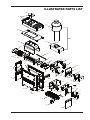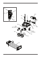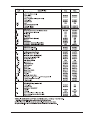
1
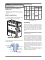
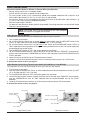
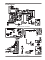
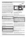
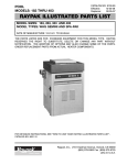
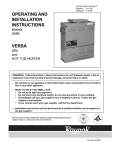
INSTALLATION & OPERATING
INSTRUCTIONS
Atmospheric
Above-Ground
Pool & Spa
Heater
(Chauffe-Piscine)
Models 106 & 156
English/French
WARNING: If the information in these
instructions are not followed exactly, a fire or
explosion may result causing property
damage, personal injury or death.
FOR YOUR SAFETY: Do not store or use
gasoline or other flammable vapors and
liquids or other combustible materials in the
vicinity of this or any other appliance. To do
so may result in an explosion or fire.
WHAT TO DO IF YOU SMELL GAS:
• Do not try to light any appliance.
• Do not touch any electrical switch; do not
use any phone in your building.
• Immediately call your gas supplier from a
neighbor's phone. Follow the gas supplier's instructions.
• If you cannot reach your gas supplier, call
the fire department.
Installation and service must be performed by
a qualified installer, service agency or the gas
supplier.
AVERTISSEMENT: Assurez-vous de bien suivre
les instructions données dans cette notice pour
réduire au minimum le risque d’incendie ou
d’explosion ou pour éviter tout dommage matériel,
toute blessure ou la mort.
Ne pas entreposer ni utiliser d’essence ou ni
d’autres vapeurs ou liquides inflammables à
proximité de cet appareil ou de tout autre appareil.
CE
DE
•
•
FAIRE SI VOUS SENTEZ UNE ODEUR
GAZ:
Ne pas tenter d’allumer d’appareil.
Ne touchez á aucun interrupteur; ne pas
vous servir des téléphones se trouvant dans
la bâtiment.
• Appelez immédiatement votre fournisseur
de gaz depuis un voisin. Suivre les instructions du fournisseur.
• Si vous ne pouvez rejoindere le fournisseur,
appelez le service es incendies.
L’installation et l’entretien doivent être assurés
par un installeur qualifié ou par le fournisseur de
gaz.
This manual should be maintained in legible condition and kept adjacent to the heater or in another safe place for
future reference.
CATALOG NO. 6100.62C
Effective: 01-15-15
Replaces: 12-18-13
P/N 241519 Rev. 4
Rev. 4 reflects the following:
Changes to: “Program Button” on page 20, “Illustrated Parts List” on page 35-38.
Additions: None
Deletions: None
2
CONTENTS
WARNINGS
Pay Attention to These Terms
WATER CHEMISTRY
Automatic Chlorinators &
Chemical Feeders
SAFETY
Water Temperature Safety
INTRODUCTION
Ratings & Certifications
Model Identification
Specifications
Unpacking
INSTALLATION
Installation Codes
Installation Codes
Clearances
Base Installation
Outdoor Installation
Indoor Installation
Combustion & Ventilation Air
Gas Connections
Water Connections
Electrical Connections
OWNER’S OPERATING
INSTRUCTIONS
Control Adjustments—Analog
Control Adjustments—Digital
Thermostat Operation—Advanced Flame
Technology (AFT) Board
20
Status and Diagnostics
22
Remote Control Installation
23
Wiring Diagrams
25
Post Start-Up Inspection
26
Cold Weather Operation
26
MAINTENANCE
27
SERVICE
27
Water Pressure Switch
27
Flame Roll-Out Safety Switch
28
High Limits
28
Burner Tray Removal
29
Gas Valve Removal
29
Pilot Removal & Cleaning
30
Heat Exchanger Removal
31
Tube Cleaning Procedure
31
De-sooting Procedure
31
Replacement Parts
31
TROUBLESHOOTING
32
Mechanical
32
Electronic Control Logic Flowchart
33
Analog Control Logic Flowchart
34
ILLUSTRATED PARTS LIST
35
4
4
5
5
6
6
6
6
7
7
7
8
9
10
10
10
10
12
12
13
15
17
18
18
18
3
WARNINGS DANGER:
WARNING:
CAUTION:
NOTE:
Pay Attention to These Terms
Indicates the presence of immediate hazards which will cause severe
personal injury, death or substantial property damage if ignored.
Indicates the presence of hazards or unsafe practices which could cause
severe personal injury, death or substantial property damage if ignored.
Indicates the presence of hazards or unsafe practices which could cause
minor personal injury or product or property damage if ignored.
Indicates special instructions on installation, operation, or maintenance which
are important but not related to personal injury hazards.
DANGER: Failure to install the drafthood on indoor
installation and properly vent the heater to the
outdoors as outlined in the venting section of this
manual can result in unsafe operation of the heater.
To avoid the risk of fire, explosion, or asphyxiation
from carbon monoxide, never operate this heater
unless it is properly vented and has an adequate air
supply for proper operation. Be sure to inspect the
vent system for proper installation at initial start-up,
and at least annually thereafter. Refer to the venting
section of this manual for more information regarding
vent system inspections.
WARNING: Both natural gas and propane have an
odorant added to aid in detecting a gas leak. Some
people may not physically be able to smell or
recognize this odorant. If you are unsure or
unfamiliar with the smell of natural gas or propane,
ask your local gas supplier. Other conditions, such
as "odorant fade," which causes the odorant to
diminish in intensity, can also hide, camouflage, or
otherwise make detecting a gas leak by smell more
difficult.
WARNING: To minimize the possibility of improper
operation, serious personal injury, fire, or damage to
the heater:
WARNING: UL recognized fuel gas detectors are
recommended in all enclosed propane and natural
gas applications wherein there is a potential for an
explosive mixture of fuel gas to accumulate and their
installation should be in accordance with the
detector manufacturer's recommendations and/or
local laws, rules, regulations, or customs.
•
WARNING - CALIFORNIA PROPOSITION
65: This product contains chemicals known to the
State of California to cause cancer, birth defects or
other reproductive harm.
•
Always keep the area around the heater free of
combustible materials, gasoline, and other
flammable liquids and vapors.
Heater should never be covered or have any
blockage to the flow of fresh air to the heater.
WARNING: Do not install within 3 feet (0.9 m) of a
heat pump or an outdoor condensing unit. Strong air
intake from this type of equipment can disturb the
combustion process and cause damage or personal
injury.
WARNING: Improper installation, adjustment,
alteration, service, or maintenance can cause
property damage, personal injury or loss of life.
Refer to the owner’s operating instructions provided
in this manual. Installation and service must be
performed by a qualified installer, service agency, or
the gas supplier.
WARNING: The heater shall not be located in an
area where water sprinklers, or other devices, may
cause water to spray through the cabinet louvers and
into the heater. This could cause internal rusting or
damage electrical components, and void the warranty.
WARNING: Gasoline, as well as other flammable
materials and liquids (adhesives, solvents, etc.), and
the vapors they produce, are extremely dangerous.
Do not handle, use, or store gasoline or other
flammable or combustible materials in the vicinity of
a heater.
4
WATER CHEMISTRY
•
NOTE: Corrosive water voids all warranties.
•
Chemical imbalance can cause severe damage to
your heater and associated equipment. Maintain your
water chemistry according to Table A. If the mineral
content and dissolved solids in the water become too
high, scale forms inside the heat exchanger tubes,
reducing heater efficiency and damaging the heater. If
the pH drops below 7.2, this will cause corrosion of the
heat exchanger and severely damage the heater. Heat
exchanger damage resulting from chemical imbalance is not covered by the warranty.
Automatic Chlorinators &
Chemical Feeders
All chemicals must be introduced and completely diluted into the pool or spa water before being circulated
through the heater. Do not place sanitizing chemicals in the skimmer. High chemical concentrations
will result when the pump is not running (e.g.
overnight).
For your health and the protection of your pool equipment, it is essential that your water be chemically
balanced. The following levels must be used as a
guide for balanced water.
Chlorinators must feed downstream of the heater and
have an anti-siphoning device to prevent chemical
back-up into the heater when the pump is shut off. See
Fig. 1.
CAUTION: Free chlorine must not exceed 5 ppm
which can damage the heater and is not covered
under warranty.
•
Automatic chemical dosing devices and salt chlorinators are usually more efficient in heated water,
unless controlled, they can lead to excessive chlorine level which can damage your heater.
Further advice should be obtained from your pool
or spa builder, accredited pool shop, or chemical
supplier for the correct levels for your water.
NOTE: High chemical concentrates from feeders
and chlorinators that are out of adjustment will
cause rapid corrosion to the heat exchanger.
Such damage is not covered under the warranty.
Occasional chemical shock dosing of the pool or
spa water should not damage the heater providing
the water is balanced.
Other Pool and Spa
Types
Recommended Level(s)
Fiberglass Pools
Fiberglass Spas
Water Temperature
68-88°F (20-31°C)
89-104°F (31-40°C)
pH
7.3-7.4
7.3-7.4
7.6-7.8
Total Alkalinity (ppm)
120-150
120-150
80-120
Calcium Hardness (ppm)
200-300
150-200
200-400
Salt (ppm)
4500 Maximum
4500 Maximum
4500 Maximum
3000 Maximum**
3000 Maximum**
3000 Maximum**
Free Chlorine (ppm)*
Total Dissolved Solids
(ppm)
2-3
2-3
*Free Chlorine MUST NOT EXCEED 5 ppm!
** In salt water chlorinated pools, the total TDS can be as high as 6000 ppm.
Table A: Water Chemistry
5
68-104°F (20-40°C)
2-3
Spa
Return to Spa
SAFETY
Fig. 1: Spa/Chlorinator Setup
4. Before entering the spa or hot tub, users should
check the water temperature with an accurate
thermometer; spa or hot tub thermostats may err
in regulating water temperatures by as much as
4°F (2.2°C).
This appliance is to be installed and operated by
trained personnel in accordance with this Installation
and Operation Manual. Be sure to read and understand the entire Installation and Operation Manual
before attempting to install or operate this appliance.
Failure to follow the warnings listed at the beginning of
this manual could result in a fire or explosion, causing
property damage, bodily injury, or death.
5. Persons with a medical history of heart disease,
circulatory problems, diabetes, or blood pressure
problems should obtain a physician's advice
before using spas or hot tubs.
Should you have any problems understanding the
warnings and instructions in this manual, STOP, and
get help from a qualified installer, service technician,
or the gas supplier.
6. Persons taking medications which induce drowsiness, such as tranquilizers, antihistamines,
anticoagulants, or recreational drugs should not
use spas or hot tubs.
Water Temperature Safety
AVERTISSEMENT: La U.S. Consumer Product
Safety Commission indique que des températures
de l’eau élevées deuvent être dangereuses. Voir la
notice d’installation et de fonctionnement pour le
réglage de lat température. Suivre les instructions
pour une installation appropriée.
Elevated water temperature can be hazardous. The
U.S. Consumer Product Safety Commission has these
guidelines:
1. Spa water temperatures should never exceed
104°F (40°C). A temperature of 100°F (38°C) is
considered safe for a healthy adult. Special caution is suggested for young children.
INTRODUCTION
Ratings & Certifications
2. Drinking of alcoholic beverages before or during
spa or hot tub use may cause drowsiness which
could lead to unconsciousness and subsequently
result in drowning.
3. Pregnant Women Beware! Soaking in water over
102°F (39°C) may cause fetal damage during the
first three months of pregnancy resulting in the
birth of a brain-damaged or deformed child.
Pregnant women should stick to the 100°F (38°C)
maximum rule.
This pool & spa heater (chauffe-piscine) is design-certified and tested under the latest requirements of ANSI
Z21.56 / CSA 4.7 Standard for Gas-Fired Pool Heaters
(Chauffe-Piscines). The heater can be used either
indoors or outdoors. (Installer å l’intérieur ou à l’extérieur.) If necessary, the top of the heater can be
changed after installation to accommodate indoors or
outdoors.
6
Specifications
WARNING: Use of any parts not manufactured
and/or approved by the manufacturer may cause
non-warrantable damage.
Ambient Temperature Rating of
Components
• Analog heater -40°F to +175°F (-40°C to 79.4°C)
• Electronic heater -32°F to +175°F (-35.5°C to
79.4°C)
Model Identification
Model
No.
Input*
106
105,000
BTU/hr.
(30.75
KW)
156
The model identification number and heater serial
number are found on the heater rating plate.
150,000
BTU/hr.
(43.93
KW)
Gas
Conn.
(NPT)
Water
Conn.
(NPT)
1/2 in.
(1.27
cm)
1-1/2 in.
or 2 in.
(3.8cm
or 5
cm)
Shipping Weight
Std.
Heater w/
Stackless
Top
85 lbs.
(38.6 kg)
100 lbs.
(45.4 kg)
Drafthood
Assembly
14 lbs.
(6.35 kg)
Table B: Specifications
Unpacking
On receipt of the heater it is suggested that visual
checks are made for external damage to the shipping
carton. If the carton is damaged, make a note to that
effect on the Bill of Lading when signing for the shipment. Remove the heater from the shipping
packaging. Report any damage to the carrier immediately.
On occasion, items are shipped loose. Be sure that the
correct number of packages are received, as indicated
on the Bill of Lading.
Claims for shortages and damages must be filed with
the carrier by consignee. Authorization to return goods
must be received from the factory prior to shipping.
Goods returned to the factory without an authorized
Returned Goods Receipt number will not be accepted.
All returned goods are subject to a restocking charge.
Fig. 2: Location of Heater Rating Plate
The model identification number will be similar to the
example shown below:
When ordering parts, specify the model and serial
number of the heater. When ordering under warranty
conditions, specify the date of installation. Records of
the installation must be provided, when requested, to
substantiate a claim.
P - R 106 A - E N - C
Plastic Header
R = Raypak
M = Rheem
D = Ruud
Model No.
Model Rev.
C = Copper
Debits for defective replacement parts will not be
accepted and will only be replaced in kind per the
manufacturer's standard warranties.
N = Natural
P = Propane
E = Electronic
A = Analog
7
INSTALLATION
CALIFORNIA PROPOSITION 65 WARNING: This product contains chemicals known to the State of California
to cause cancer, birth defects or other reproductive harm.
WARNING: This unit contains refractory ceramic fiber (RCF) insulation in the combustion chamber. RCF, as
manufactured, does not contain respirable crystalline silica. However, following sustained exposure to very
high temperatures (>2192F), the RCF can transform into crystalline silica (cristabolite). The International
Agency for Research on Cancer (IARC) has classified the inhalation of crystalline silica (cristabolite) as carcinogenic to humans.
When removing the burners or heat exchangers, take precautions to avoid creating airborne dust and avoid
inhaling airborne fibers. When cleaning spills, use wet sweeping or High Efficiency Particulate Air (HEPA)
filtered vacuum to minimize airborne dust. Use feasible engineering controls such as local exhaust ventilation
or dust collecting systems to minimize airborne dust. Wear appropriate personal protective equipment
including gloves, safety glasses with side shields, and appropriate NIOSH certified respiratory protection, to
avoid inhalation of airborne dust and airborne fiber particles.
IMPORTANT NOTICE
These instructions are intended only for the use by qualified personnel, specifically trained and experienced in the installation of this type of heating equipment and related system components. Installation
and service personnel may be required by some states to be licensed. If your state is such, be sure your contractor bears the appropriate license. Persons not qualified shall not attempt to fix this equipment nor attempt
repairs according to these instructions.
WARNING: Improper installation, adjustment, alteration, service or maintenance may damage the equipment, create a hazard resulting in asphyxiation, explosion or fire, and will void the warranty.
8
9
Installation Codes
However for ease of servicing, we recommend a
clearance of at least 18" (45.7cm) on the rear. This
will enable the heater to be serviced in its installed
location, that is, without movement or removal of the
heater.
Installations must be in accordance with local, state,
provincial, and national codes, laws, regulations and
ordinances. In the absence of local codes, installations
must be in accordance with the latest editions of the:
Minimum clearance from drafthood to combustible
construction 6 inches from the vent.
• National Fuel Gas Code, ANSI Z223.1/NFPA 54
• National Electrical Code, ANSI/NFPA 70
• For Canada only: CAN/CSA-B149 Installation Code
(B149) and CSA C22.1 C.E.C. Part 1 and Part 2
Degagement minimal de 6 po requis entre le coupetirage et une construction combustible. 2 po du conduit
de raccordement.
AVERTISSEMENT: Cet appareil doit être installé
conformément au National Fuel gas Code ANSI
Z223.1, et aux exigences de l’autorité competente.
Clearances less than recommended may require
removal of the heater to service either the heat
exchanger or the burner tray. In either case, the heater
must be installed in a manner that will enable the
heater to be serviced without removing any structure
around the heater.
NOTE: The heater should not be located in an area
where possible water leakage will result in damage
to the area adjacent to the heater or to the structure.
When such locations cannot be avoided, it is
recommended that a suitable drain pan, with
adequate drainage, be installed under the heater.
The pan must not restrict combustion air flow.
FLOORING: This heater can be installed on combustible flooring.
Base Installation
Clearances
Heater must be mounted on a level base, such as
cementable slab or cement blocks. Heaters may not
be installed on carpeting.
The required minimum clearances from combustible
surfaces are shown in Table C below.
Heater Side
Top*
Front
Vent
Back
Right Side
Left Side
Outdoor
Installations
Indoor
Installations
Unobstructed
30 in. (76.2 cm)
N/A
6 in. (15.2 cm)
6 in. (15.2 cm)
6 in. (15.2 cm)
24 in. (61 cm)
This heater must be installed at least 5ft (1.52m) from
the inside wall of a pool unless separated from the
pool by a solid fence, wall or other permanent solid
barrier.
Ce chauffe-piscine doit êntre installè à au moins 5
peds (1.52m) de la paroi interne de la piscine à moins
d’êntre isolé de la piscine par un clôture, un mur ou
autre barrière permanente.
Alcove
12 in. (30.5 cm) 12 in. (30.5 cm)
6 in. (15.2 cm)
*Clearance from top of vent terminal.
Outdoor Installation
6 in. (15.2 cm)
WARNING: The heater should not be located in an
area where water sprinklers or other devices may
cause water to spray through the cabinet louvers
and into the heater. This could cause internal rusting
or damage electrical components, and will not be
covered under warranty.
Table C: Required Minimum Clearances from
Combustible Surfaces.
Dégagements minimaux à assurer entre les parois de
l”appareil et les contructions combustibles: 6po
(côtés), 12po (arrière) et 30po (dessus).
WARNING: Do not install within 3 feet (0.9m) of a
heat pump or an outdoor condensing unit. Strong air
intake from this type of equipment can disturb the
combustion process and cause damage or personal
injury.
When installed according to the listed minimum clearances from combustible construction, the pool heater
can be serviced without removing permanent construction around the heater.
10
Amp Draw
120 Volt 240 Volt
4
2
Fig. 3: Overall Dimensions
Outdoor Stack
NOTE: This heater is design-certified for outdoor
installation when equipped with the approved top(s)
for outdoor use.
NOTE: The outdoor stack is optional equipment and
does not come standard with the heater. Use part
number 014718 for the 106 and 014719 for the 156.
Heater with Outdoor Stackless Top
High Wind Conditions
(Outdoor Units Only)
Heaters must not be installed under an overhang of
less than 3 ft (0.9m) from the top of the heater. Three
sides must be open in the area under the overhang.
Roof water drainage must be diverted away from
heaters installed under overhangs with the use of gutters.
In areas where high winds are frequent, it may be necessary to locate the heater a minimum of 3 ft (0.9m)
from high vertical walls, or install a wind-break so the
heater is not in direct wind current.
Ne pas installer ce chauffe-piscine sous une saillie
mesurant moins de 3 pi de hauteur. La partie sous Ia
saillie doit etre ouverte sur 3 côtes.
In areas of daily high winds, it may be necessary to
replace the outdoor stackless top with a stack adapter
in combination with a wind-resistant/weather-proof
outdoor stack. See Fig. 4.
• For U.S. installations, the point from where the flue
products exit the heater must be a minimum of 4 ft
(1.2m) below, 4 ft (1.2m) horizontally from, or 1 ft
(0.3m) above any door, window or gravity inlet into
any building. The top surface of the heater shall be at
least 3 ft (0.9m) above any forced air inlet, or intake
ducts located within 10 ft (3m) horizontally. See
Fig. 5.
OUTDOOR
STACK
• For installations in Canada, pool heaters shall not be
installed with the top of the vent assembly within 10 ft
(3m) below, or to either side, of any opening into the
building. Refer to the latest revisions of CAN/CSAB149. The heater must be raised 7 in (0.2m) above
the surface which could support snow, ice or debris.
Refer to the latest revisions of CAN1-2.21-M85.
11
Fig. 4: Outdoor Stack
The outdoor stack serves the same function as the low
profile stackless top and should be installed in accordance with the same clearance requirements. Follow
the installation instructions provided with the Outdoor
Stack Kit for installation.
CAUTION: Combustion air must not be
contaminated by corrosive chemical fumes which
can damage the heater and void the warranty. Do
not store chlorine, bromine, baquasil or acid in the
same room as the heater.
Indoor Installation
•
The heater is design-certified for indoor installation
when equipped with the approved drafthood.
Model
NOTE: For Canada, indoor installation is restricted
to an enclosure that is not occupied and does not
directly communicate with an occupied area. Refer
to the latest edition of CAN/CSA-B149 for specific
requirements.
106
156
•
WARNING: Indoor heaters require a drafthood
that must be connected to a vent ppe and properly
vented to the outside. Failure to follow this
procedure can cause fire or fatal carbon monoxide
poisoning.
150 in² (968 cm²)
Table E: Minimum Air Area
All air from outdoors when air is supplied directly
from outside the building each opening shall have
a minimum net free area as noted in Table D.
If installation requires horizontal runs, the vent pipe
must have a minimum of 1/4 in. (2cm per m) per ft rise
and should be supported at not more than five foot
intervals. Plumbers tape, criss-crossed, will serve to
space both horizontal and vertical piping. Gas vents
supported only by the flashing and extending above
the roof more than 5 ft (1.5m) should be securely
guyed or braced to withstand snow and wind loads.
We recommend use of insulated vent pipe spacers
through the roof and walls.
Ce coupe-tirage doit être installé sans modification.
Voir Ia plaque signalétique.
Combustion & Ventilation Air
(Indoor Units Only)
The heater must have both combustion and ventilation
air. Minimum requirements for net free air supply
openings are one opening that is 12 inches (30.5 cm)
from the ceiling for ventilation, and one opening that is
12 inches (30.5 cm) from the floor for combustion air
as outlined in the latest edition of the National Fuel
Gas Code, ANSI Z223.1 (Canada-CAN/CSA-B149)
and any local codes that may have jurisdiction.
156
105 in² (677 cm²)
Vent piping the same size as the drafthood outlet is
recommended, however, when the total vent height is
at least 10 ft (3m) (drafthood relief opening to vent terminal), the vent pipe size may be reduced as specified
in the National Fuel Gas Code, ANSI Z223.1 (Canada
- CAN/CSA-B149). As much as possible, avoid long
horizontal runs of vent pipe and too many elbows.
This drafthood must be installed without alteration. see
rating plate.
106
Area
Vent Piping
Locate heater as close as is practical to a chimney or
gas vent. Heater must always be vented to the outside. See Vent Piping section for details. Minimum
allowable space is shown on the rating plate. Follow
the installation instructions provided with the Indoor
Drafthood Kit for installation.
Model
All Air from inside the building each opening shall
have a minimum net free area as noted in Table E.
For protection against rain or blockage by snow, the
vent pipe must terminate with a vent cap which complies with local codes or, in the absence of such codes,
the latest edition of the National Fuel Gas Code, ANSI
Z223.1 (Canada - CAN/CSA-B149).
Unrestricted
opening
Typical screened
or louvered opening
Typical screened
and louvered opening
38 in² (245 cm²)
57 in² (368 cm²)
76 in² (490 cm²)
27 in² (174 cm²)
41 in² (265 cm²)
Table D: Minimum Air Net Area
12
54 in² (348 cm²)
4 ft (1.2m)
4 ft (1.2m)
4 ft (1.2m)
3 ft (0.9m)
1 ft (0.3m)
10 ft (3m)
Fig. 5: Outdoor Installation Clearances
The discharge opening must be a minimum of 2 ft
(0.6m) vertically from the roof surface and at least 2 ft
(0.6m) higher than any part of the building within 10 ft.
(3m) vent stack shall be at least 5 ft (1.5m) in vertical
height above the drafthood outlet. The vent cap location shall have a minimum clearance of 4 ft (1.2m)
horizontally from, and in no case below, unless a 4 ft
(1.2m) horizontal distance is maintained, from electric
meters, gas meters, regulators and relief equipment.
The weight of the vent stack or chimney must not rest
on heater drafthood. Support must be provided in
compliance with applicable codes. The heater top and
drafthood must be readily removable for maintenance
and inspection. Vent pipe should be adequately supported to maintain proper clearances from combustible
construction.
Type "B" double-wall or equivalent vent pipe is recommended. However single-wall metal vent pipe may be
used as specified in the latest edition of the National
Flue Gas Code ANSI Z223.1 (Canada - CAN/CSAB149).
10’ (3m)
OR LESS
2’ (0.6m)
MIN
2’ (0.6m)
MIN
Gas Connections
Gas piping must have a sediment trap ahead of the
heater gas controls, and a manual shut-off valve located outside the heater jacket. All gas piping should be
tested after installation in accordance with local codes.
5’ (1.5m)
MIN
CAUTION: Do not use 5, 10 or 20 gallon (19.38 or
76 Liter) propane tanks, like those used with consumer barbecues, to supply gas to this heater.
Fig. 6: Vent Piping Requirements
CAUTION: The heater and its manual shut-off
valve must be disconnected from the gas supply
during any pressure testing of that system at test
pressures in excess of 1/2 psig (3.5 kPa). The heater
and its gas connections shall be leak tested before
placing the appliance in operation. Use soapy water
for leak test. do not use open flame.
13
Gas Pressure Adjustment Locations
Fig. 8: Honeywell Gas Valve
Fig. 7: Gas Line Sediment Trap
Electronic Ignition Gas Valves
NOTE: Do not use Teflon tape on gas line pipe
thread. A flexible pipe sealant suitable for LP gases
is recommended.
Gas Pressure Regulator
The gas pressure regulator is preset at 4.0 in W.C.
(1.0kPa) for natural gas and 10.0 in W.C. (2.5kPa) for
propane gas.
If adjustment is needed, remove plug and turn adjustment screw clockwise to increase pressure or
counter-clockwise to decrease pressure.
Gas Pressure*
Natural Gas
Propane Gas
Min. Inlet
(dynamic)
5 in. WC
(1.2 kPa)
11 in. WC
(2.7 kPa)
Max. Inlet
(static)
Manifold Gas
(dynamic)
10.5 in. WC
(2.6 kPa)
4 in. WC
(1.0 kPa)
13 in. WC
(3.2 kPa)
Fig. 9: Location of Gas Pressure Adjustment
10 in. WC
(2.5 kPa)
*Static means without heater operating, dynamic refers to heater
operating.
Table F: Gas Pressure
14
Pipe Sizing for Gas Connections
Model
Tubing
106
Cu
156
Cu
Input
105,000 BTU/hr
(30.8 kW)
150,000 BTU/hr
(43.9 kW)
1/2 in. (1.27cm)
NAT
LPG
26 ft
65 ft
(8 m)
(20 m)
13 ft
34 ft
(4 m)
(10 m)
3/4 in. (1.91cm)
NAT
LPG
99 ft
252 ft
(30 m)
(77 m)
51 ft
130 ft
(16 m)
(40 m)
1 in. (2.54cm)
NAT
LPG
350 ft
892 ft
(107 m) (272 m)
180 ft
459 ft
(55 m)
(140 m)
* Natural Gas 1000 BTU/FT3 0.60 Specific Gravity @ 0.5 in WC Pressure Drop
(Gaz Naturel 3154.5 W/m3 0.60 Densité @ 0.124 kPa Pressure Drop)
* Propane Gas 2500 BTU/FT3 1.53 Specific Gravity @ 0.5 in WC Pressure Drop
(Le Gaz Propane 7886.3 W/m3 1.53 Densité @ 0.124 kPa Pressure Drop)
Water Connections
Table G: Maximum Equivalent Pipe Length
Polymer Headers
Before attaching the supplied 2-inch (5 cm) CPVC
unions to the In/Out header, make sure the O-rings are
properly seated in the grooves. Use AquaLube or
equivalent non-petroleum-based lubricant on the Oring. Hand tighten the unions. Glue PVC or CPVC
piping directly to the unions.
The heater requires water flow and positive pressure
to fire and operate properly. It must therefore be
installed downstream of the discharge side of the filter
pump. A typical installation is plumbed as follows:
1. The inlet side of the filter is plumbed directly to the
discharge side of the filter pump;
2. The outlet side of the filter is then plumbed to the
inlet of the heater; and
In/Out Header
O-Ring
Tail Piece
3. The outlet of the heater is plumbed to the return
line to the pool or spa. The pump, filter and heater
are thus plumbed in series.
Nut
2” Pipe
(5cm)
Plumbing from the heater back to the pool or spa must
not have any valves or restriction that could prevent
flow when the pump is operating.
Drain Plug
Heater must be located so that any water leaks will not
damage the structure of adjacent area. PVC pipe may
be glued directly into supplied CPVC header unions.
Fig. 10: In/Out Header for 2" Installation
Flow Rates
Model No.
106/156
In/Out Header
Minimum
20 GPM (75 L)
Maximum
Hose Connector
70 GPM (265 L)
Hose
*When flow rates exceed maximum 70 GPM, an external auxiliary
bypass valve is required. See External Auxiliary Bypass Valve section for details.
Table H: Water Flow Rates
Fig. 11: Optional In/Out Header for 1-1/2" (3.8 cm)
or 1-1/4" (3.2 cm) Hose Connection
15
If there is any possibility of back-siphoning when the
pump stops, it is recommended that a check valve (or
valves) also be installed in the system.
NOTE: Do not use a gate valve as an auxiliary
bypass valve.
Auxiliary Bypass Valve Adjustment
Internal Automatic Bypass Valve
To set bypass: With clean filter, adjustment is made by
feeling the inlet and outlet pipes at the heater. Outlet
pipes should be slightly warmer than inlet and comfortable to the touch. If pipe is hot, close bypass; if cold,
open bypass.
A built-in automatic bypass valve is provided in the
In/Out header. The internal bypass valve automatically responds to changes in water pressure in the piping
system. The proper amount of water flow is maintained
through the heater under varying pressures dictated
by the conditions of the pump and filter.
Pressure Relief Valve Installation
To conform to local building codes, it may be necessary to install a pressure relief valve. A 3/4" (1.9 cm)
pressure relief valve, having a capacity equal to or
greater than the BTUH input of the heater to be
installed, is recommended for this heater. The maximum pressure relief valve setting is 125 psi (862 kPa).
This relief valve needs to be installed on the outlet pipe
from the header as noted in Fig. 14 below.
Bypass Disc
Spring
PIPE ONTO DISCHARGE SIDE OF PIPING
Bypass Body
Fig. 12: Internal Automatic Bypass Valve
External Auxiliary Bypass Valve
An auxiliary bypass valve must be used when flow
rates exceed 70 GPM (265 LPM). Usually a high-performance pump size larger than one horsepower will
exceed this flow rate. This valve is required to complement the function of the automatic bypass valve,
particularly when starting the heater in winter or early
spring when the spa or pool temperature is below 50°F
(10°C). It also serves to eliminate needless pressure
drop through the heater and accompanying reduction
in the flow rate to the spa jets, etc.
From Heater
Fig. 14: Pressure Relief Valve Installed
If required, this needs to be installed in a field-supplied
fitting external to the heater. The valve shall be
installed in a vertical position. Do not over-tighten.
Install the pressure relief valve hand tight plus 1/2 turn.
To Heater
WARNING: To avoid water damage or scalding due
to relief valve operation, drain pipe must be
connected to valve outlet and run to a safe place of
discharge. Drain pipe must be the same size as the
valve discharge connection throughout its entire
length and must pitch downward from the valve. No
shut-off valve shall be installed between the relief
valve and the drain line.
Full Port
Ball Valve
or Globe
Valve
To Pool/Spa
Bypass Valve
The valve lever should be tripped at least once a year
to ensure that waterways are clear. If the relief valve
does not function properly, replace it immediately.
From
Pool/Spa
Fig. 13: Auxiliary Bypass Valve
16
Heat Exchanger Pressure Drop
Table
Flow (GPM)
Pressure Drop (ft of Head)
30
8.2
20
40
50
60
70
The heater must be electrically grounded and bonded
in accordance with local codes, or, in the absence of
local codes, with the latest edition of the National
Electrical Code, ANSI/NFPA 70. (Canada - Canadian
Electrical Code, CSA C22.1, Part 1 and Part 2.)
7.6
NOTE: Input power to the heater (120 VAC) can be
supplied from the load (pump) side of time clock or
directly from the GFCI power source. It is preferred
to make connection to the load/pump side of the time
clock.
8.7
9.3
9.8
WARNING: Risk of electrical shock. More than
one disconnect switch may be required to deenergize the equipment before servicing.
10.4
Table I: Pressure Drop
CAUTION: Label all wires prior to disconnection
when servicing controls. wiring errors can cause
improper and dangerous operation.
Electrical Connections
Be sure that electrical service to the heater has proper overload fuse or circuit breaker protection, wire size
and connections which comply with all applicable
codes.
Installation Instructions—240 Volt
CAUTION: This heater has provisions to be
connected to an alternate supply source. To reduce
the risk of electric shock, disconnect all connections
before servicing.
If any of the original wire as supplied with the appliance must be replaced, it must be replaced with type
302°F (150°C) wire or its equivalent.
1. Disconnect the 120V power cord from power
source.
2. Remove knurled screw from the lower front panel.
3. Remove the front panel and set aside.
4. Remove the two stainless screws holding the control panel in place.
5. Lower the control panel and then sway it forward.
The 120V wiring should be visible next to the
transformer.
6. Disconnect and remove the 120V power cord from
the heater.
7. Bring the 240V supply line into the control box.
8. Install a wire nut on the white transformer wire.
(See Fig 16)
9. Wire nut the 240V supply lines to the red and
black wires on the transformer. (See Fig 16)
Si un des fils original fourni avec l'appareil doit être
remplacé, utilisez un fil 302°F (150°C), ou l'équivalent.
The heater comes standard with a 120 VAC 3-prong
power cord. For 240 VAC applications, see figure 16.
Power source must be a wired ground, with ground
fault circuit interruption circuitry.
240V HOOK-UP
SUPPLY
SIDE
Fig. 15: Electronic Heater Power
ATTENTION. Au moment de l'entretien des
commandes, étiquetez tous les fils avant de les
débrancher. Des erreurs de câblage peuvent
entraîner un fonctionnement inadéquat et
dangereux.
L1
L2
HOT
BLACK
BLACK
RED
RED
GREEN
GREEN
HOT
WHITE
17
Fig. 16: 240V Hook-Up
HEATER
10. Wire nut the supply ground line to the green transformer wire. (See Fig 16)
11. Reposition the control panel back in place and reinstall the two screws.
12. Re-install front panel and knurled screw.
OWNER’S OPERATING
INSTRUCTIONS
Control Adjustments—Analog
The pool or spa water temperature is controlled by the
thermostat on the upper front panel of the heater. The
control center contains an On/Off toggle switch and a
thermostat. The switch functions as a means for turning the heater On or Off.
The thermostat is fitted with a means of limiting the
upper temperature limit below the maximum level. The
knob stop adjustment ring shown in Fig. 17 is
adjustable by loosening the set screw, rotating the
knobstop ring to the desired location, and retightening
the set screw.
Fig. 18: Digital Control Adjustment
MENU/SET Button
The MENU/SET button is used to select either POOL
or SPA operation. It also allows the user to turn the
heater off electronically. The LCD remains energized
and displays OFF, while also continuing to show the
actual water temperature.
HOT
Temp Buttons
If the heater is in POOL or SPA mode, the desired
water temperature (SETPOINT) will also be displayed
and may be adjusted using the UP or DOWN buttons.
Operation
In the POOL or SPA modes, the actual water temperature is displayed along with the desired water
temperature (SETPOINT). When the water temperature is above the setpoint, “Water Temp” will alternate
with “No Demand.” When the water temperature is
below the setpoint and the heater is firing, “Water
Temp” will alternate with “Heating.”
COOL
Knobstop Set Screw
Knobstop Ring
Fig. 17: Water Temperature Thermostat
To adjust the setpoint temperature, make sure the control is in the appropriate mode (POOL or SPA) and
push the UP or DOWN buttons.
NOTE: Maximum temperature is 104°F (40°C).
Control Adjustments—Digital
The pool heater (chauffe-piscine) touchpad, located
on the upper front panel of the heater, allows the user
to select either POOL or SPA operation, and to adjust
the setpoint temperature. The LCD display window
indicates the mode (OFF, SPA, POOL) and the actual
water temperature. A manual power switch provided
below the touchpad turns the control power ON or
OFF.
18
ALTERNATING DISPLAYS DURING HEATING
19
Thermostat Operation—
Advanced Flame Technology (AFT) Board
Program
button
Service Menu and Fault History
To access the Service Menu and fault history, press
the MENU/SET and UP buttons simultaneously for 3 to
5 seconds. The heater will continue to operate normally while in the Service Menu. The first screen
displayed is the Flame Strength indicator, which indicates the pilot flame current using a bar graph and
numerical display. A signal of less than 4 indicates a
weak flame signal and may require service. Refer to
Section 5 – Troubleshooting for possible causes and
corrections.
Press the DOWN button. The Run Time indicates the
total hours of operation for the pool heater, as measured by the amount of time that the main gas valve has
been powered. The Cycle count indicates the number
of on/off cycles of the heater, as measured by the
number of times the pilot valve has been powered.
RUN TIME INDICATOR
Press the DOWN button. The Fault History can display up to ten faults in memory. The order of the faults
begins with “Fault Last,” which is the most recent fault,
and proceeds through ten most recent messages in
chronological order. The second line of the display
shows the fault message. If there are no faults in the
history buffer, the second line reads “All Faults Clear.”
FLAME STRENGTH INDICATOR
Press the DOWN button. The Supply Voltage screen
indicates the voltage supplied to the control board.
Normal readings range from 24 to 29 volts.
FAULT HISTORY
SUPPLY VOLTAGE INDICATOR
20
Fahrenheit or Celsius
Refer to step one above to access the program
screen. Press the MENU/SET button until Fahrenheit
or Celsius appears on the digital display. The digital
display is capable of displaying Celsius as well as
Fahrenheit temperatures. The UP or DOWN buttons
will select Fahrenheit or Celsius on the temperature
display. Choose the desired temperature scale.
Program Button
1) Remove the two screws holding the control cover,
and swing the panel down so the back side of the
board is visible (see page 19). Locate the Program
Mode button (marked as SW1) as shown on page
19. Press and hold the button (5-7 seconds) until
Set Factory Defaults appears on the display.
Release the program button.
Spa Max Temp – Spa Set Point Maximum
Adjustment
Refer to step one above to access the program
screen. Press the MENU/SET button until Spa Max
Temp appears on the digital display. Using the UP and
DOWN buttons will change the Maximum Temperature
Setting to your desired value. The control can be set
for a maximum of 107°F (41.7°C).
2) Press the MENU/SET button sequentially until the
desired program event is reached. There are 5 different events that can be programmed. They
appear in the sequence listed below:
Resets board to factory default
settings.
Pool Max Temp – Pool Set Point Maximum
Adjustment
Refer to step one above access into the program
screen. Press the MENU/SET button until Pool Max
Temp appears on the digital display. Using the UP and
DOWN buttons will change the Maximum Temperature
Setting to your desired value. The control can be set
for a maximum of 107°F (41.7°C).
Resets faults in the History File.
Change from Fahrenheit to
Celsius.
Control Lockout
The heater is equipped with a Control Lockout feature
to prevent unauthorized tampering or adjustment of
the control settings. To lock out the controls, press the
DOWN button and MENU/SET button for 5 seconds.
Choose a three digit PIN, using the UP and DOWN
buttons to select the digits and the MENU/SET button
to lock in selections. Confirm your selection and
record your PIN.
SPA setpoint maximum adjustment.
POOL setpoint maximum
adjustment.
Set Factory Defaults
Refer to step one above to access the program
screen. Set Factory Defaults should appear on the
screen. If it does not, press the MENU/SET button until
Set Factory Defaults appears on the digital display.
Press and hold both UP and DOWN buttons for 5-7
seconds until Defaults Set appears. This operation
resets the operating program to its factory default values. Both the POOL and SPA setpoints will revert to
65°F (18.5°C) and both POOL and SPA maximum
temperature settings will be 104°F (40.0°C). The
Control Lockout PIN will be cleared and the control will
resume normal operation.
To unlock the controls, press any button to bring up the
Enter PIN menu. Enter the PIN that was used to lock
the control. Note that power cycling will not clear the
lockout. Successfully unlocking the control will display
“Lockout Cleared.” Failure to enter the correct PIN will
display “Invalid PIN.”
In the event that the user-selected PIN is lost or does
not clear the Control Lockout, use the Program Button
to Set Factory Defaults. This will clear the PIN and
allow normal operation and selection of a new PIN if
desired. See the Program Button directions on this
page for details.
Clear Faults
Refer to step one above to access the program
screen. Press the MENU/SET button until Clear
Faults appears on the digital display. Press and hold
both UP and DOWN buttons for 5-7 seconds until
Faults Cleared appears. This operation resets the
Fault History file to “0” and clears all the stored faults.
21
NOTE: Both the POOL and SPA setpoints will revert
back to 65°F (18.5°C) and the POOL and SPA maximum temperature settings will be 104°F (40.0°C).
These setpoints will need to be readjusted to desired
settings.
NOTE: The LCD temperature display may not agree with the temperature reading of your pool or spa thermometer. The heater reads the water temperature at the inlet. Due to the circulation characteristics of any pool
or spa, the water temperature at the inlet to the heater may differ from that observed at a given location in the
pool or spa.
STATUS AND DIAGNOSTICS
The digital thermostat models are programmed to display a variety of status and diagnostic messages, depending on the operating conditions.
The following heat status messages are displayed in
Pool, Spa, and Remote modes when there are no
active fault conditions.
Display
Condition
Heating
Call for heat established, flame
present
No Demand
Heat demand is satisfied
Spark
The following conditions are displayed only while there
is a demand for heat present.
Display
The following conditions are displayed in Pool, Spa
and Remote modes.
Display
Thermistor temperatures disagree
by more than 2°F (1.1°C)
Sensor Short
Thermistor sensor failed short.
(Above 217°F (103°C))
Sensor Open
Flame w/o
CFH
PV Output
Fault
MV Output
Fault
Pilot gas valve output is not in commanded state.
Water temperature below 36°F
(2°C).
High limit 2 open.
Rollout switch open.
Field-supplied flow switch/field
switch #2 open.
Ignition
Alternating with “No pilot
Failure
sensed” - Pilot flame not estab(Propane Tab
lished within 90 seconds.
Not Broken)
Main gas valve output is not in commanded state.
Low Temp
Lockout
Vent spill switch/field switch #1
open.
Alternating with “No pilot
sensed” - Pilot flame not estabIgnition
lished within the required time (15
Lockout
sec or 90 sec).
(Propane Tab Alternating with “Main Ign
Broken)
Failure” - Pilot flame lost during the
8 second trial to ignite the main
burner.
Alternating with “Main Ign
Ign 6min
Failure” - Pilot flame lost 4 times
Delay
within the 8 second trial to ignite the
(Propane Tab
main burner. Heater will lockout for
Not Broken)
6 minutes before retrying.
Internal Fault Board fault, replace board.
Clock/
Fireman Sw
High limit 1 open.
Flow/Field
SW #2
Board is sensing flame when both
main and pilot valves are commanded shut.
Memory fault, reset set points,
replace board if fault does not clear.
Hi Limit 1
Fault
Rollout Sw
Open
Thermistor sensor failed open.
(Below -20°F (-29°C))
EEPROM
Fault
Water pressure switch open.
Hi Limit 2
Fault
Condition
Sensor
Failure
Water Sw
Open
Vent/Field
Sw #1
Spark operating
Condition
Time clock/fireman switch circuit is
open.
22
REMOTE CONTROL INSTALLATION AND OPERATION
CAUTION: Before installing remote controls to the AFT thermostat model heaters, read the following:
The digital thermostat model is remote-ready in most cases. The digital liquid crystal display (LCD) shows the
actual pool temperature, operating status, and service codes (See examples below). The touch pad on the control panel allows you to select the desired pool or spa temperature. It also indicates when a remote system is
controlling the heater by displaying Remote in the display. When connecting the heater to a remote system,
identify whether it is a two- or three-wire remote system. Select the appropriate instruction listed below to properly install the remote to the heater.
OFF Mode
Heating in the POOL Mode
Heating in the SPA Mode
Pool Common
(BLK/ORN)
ACTIVATING THE REMOTE
To activate or deactivate the remote function, follow
these steps:
Spa Common
(ORN/BLK)
7-PIN Remote
Interface Harness
Remote Mode
Press and hold the UP
and DOWN arrow buttons
for 3 to 5 seconds.
24VAC HOT
(BLU)
The second line of the display will alternate even
when the unit is off (“No
Demand”).
REMOTE OPERATION
The AFT model heaters are equipped with the ability
to work with external remote controls. The supplied 7pin remote wiring connector supplies power out to
either a toggle switch or the switch contacts of a third
party remote. The remote works by either making or
breaking the circuit created by the remote wiring.
Typically, a remote does not supply power to the
heater, it only provides a switching function to turn the
heater On or Off. If your remote is supplying its own
voltage to the heater, it will not work with this
heater and may damage the digital circuit board.
For operation of the heater using the onboard thermostatic controls with a time clock, see the “Time Clock /
Fireman’s Switch” section.
NOTE: When in remote operation, the keypad
mode and temp buttons are disabled.
Note: Electrostatic Discharge (ESD) damage can be caused by
direct or indirect contact with the wiring or circuit board. When
one walks to the heater area, an electrostatic charge accumulates on the body. Contact of a finger allows the body to
discharge, possibly causing device damage. This damage can
be limited if the service person discharges himself, following ESD
preventive/removal practices, and holds on to the heater enclosure for 5 seconds before proceeding.
23
REMOTE CONTROL WIRING
Important Installation Notes for Remote or External Wiring Configuration
• Remote wiring must be run in a separate conduit.
• Remote wiring must not be run parallel to high voltage lines.
• For runs of under 30 feet (9.1m), remote wiring should have stranded conductors with a minimum of 22
AWG, 600V, cable twisting 1.5 to 2.5 in. (3.8 to 6.4cm) lay and jacketed.
• For runs over 30 feet (9.1m), the conductors should be a minimum of 20 AWG, 600V, cable twisting 1.5 to
2.5 inch (3.8 to 6.4cm) lay that is shielded and jacketed.
• Maximum cable length is 200 feet.
• For both two- and three-wire remote systems, the provided 7-pin wiring connector must be utilized. Please
refer to the wiring instructions.
NOTE: The remote wires must be connected to the 7-pin connector
before the connector is plugged into the board.
2-Wire Remote Control (On-Off)
This application assumes that only one heating function (pool or spa) is required.
1. Turn on power to the heater.
2. For a 2-Wire Remote Control from a remote without its own sensor, push the MENU/SET button to the
“POOL” or “SPA” mode and set the desired setpoint (eg. 102 °F (39°C) for Spa).
3. For a 2-Wire Remote Control from a remote with its own sensor, push the MENU/SET button “POOL” or
“SPA” mode and set the temperature to the highest setting available on the control. The actual setpoint will
be controlled by the remote control.
4. Turn the MENU/SET button to "OFF" and remove power from the heater.
5. On the "Remote Interface Harness", connect the BLUE wire to one side of the "REMOTE" switch and connect the other side to either the ORANGE/BLACK wire for "SPA" operation or the BLACK/ORANGE wire for
"POOL" operation.
6. Attach wire nut on unused wire to the "Remote Interface Harness."
7. Install the "7-Pin Remote Interface Harness" to the P8 connector and turn power “On” to the heater.
To activate the remote control, see page 23.
3-Wire Remote Control Using Three-Position Switch (Pool-Off-Spa, or Low-Off-High)
This application assumes that both heating functions (pool and spa) are required.
1. Turn on power to the heater.
2. Push the menu/set button to the "POOL" or "SPA" mode and set the desired temperature for each (eg. 80°F
(27°C) for Pool and 102°F (39°C) for Spa).
3. Turn the MENU/SET button to "OFF" and remove power from the heater.
4. On the "Remote Interface Harness" connect the BLUE wire to one side of the "REMOTE" switch and connect the ORANGE/BLACK wire for "SPA" operation and the BLACK/ORANGE wire for the "POOL"
operation.
5. Install the "Remote Interface Harness" to the P8 connector and turn power "ON" to the heater.
To activate the remote control, see page 23.
P8 Connector
P8 Connector
Wire Nut - BLK/ORN
To Pool (COMM)
BLK/ORN - To Pool (COMM)
ORN/BLK - To Spa (COMM)
ORN/BLK - To Spa (COMM)
AFT Board
BLU - 24VAC
BLU - 24VAC
2-Wire Remote Control
24
3-Wire Remote Control
AFT Board
Wiring Diagrams
Fig. 19: Wiring Diagram—Analog Models
Fig. 20: Wiring Diagram—Digital Models
25
Time Clock/Fireman’s Switch
To operate the heater with a time clock, connect the
timer to the fireman’s switch connection in the heater’s
wiring. The time clock should be of the dual switch
type and set to shut off the call for heat to the pool
heater (chauffe-piscine) 15 to 20 minutes prior to shutting down the pool pump. On analog heaters, splice
into the red/white wire to connect the time clock. For
digital heaters the fireman’s switch connection is located on the 14-pin header connected to the digital
control board. Splice into the red wire jumper tagged
“Where necessary add “Fireman’s” switch circuit here”
to connect the time clock. The fireman’s switch connection on both analog and digital heaters must be
a dry contact and must not supply power to the
heater. Powering the fireman’s switch connection
externally may damage the heater, and is not covered by warranty.
Fig. 21: IID Pilot Location
Cold Weather Operation
Moderate Climate
Digital heaters: Do not exceed 50ft (15.2 m) of total
wiring using 18 AWG stranded copper wire rated for
221°F (105°C) minimum.
Heater operation can continue during short-term cold
spells. When temperatures are between 0° (-17°C)
and 32°F (0°C), flow (continuous pump operation)
must be maintained.
NOTE: When using a time clock, the heater will
display “Clock/ Fireman Sw” when the fireman’s
switch is open, indicating that the time clock has shut
off the call for heat.
CAUTION: Do not use the heater to maintain water
temperatures just above freezing or for freeze
protection. When heater is used during freezing
weather, care must be taken to avoid freeze-ups.
Continuous pump operation is a must. Additional
protection may be required. The heater is not
warranted against freeze-ups.
Post Start-Up Inspection
Do not use this heater if any part has been under
water. Immediately call a qualified service technician
to inspect the heater and to replace any part of the
control system and any gas control which has been
under water.
Cold Climate
N'utilisez pas cet appareil s'il a ete plonge dans l'eau,
meme partiellement. Faites inspecter l'appareil par un
technicien qualifie et remplacez toute partie du systeme de controle et toute commande qui ont ete
plonges dans l'eau.
Prolonged operation with water temperatures below
50°F (10°C) is not recommended. When starting the
heater with water temperatures below 50°F (10°C),
operate the heater continuously until higher temperatures are reached. Operating the heater for prolonged
periods with pool water below 50°F (10°C) can seriously damage the heater, and is not covered by the
warranty.
WARNING: Should overheating occur or the gas
supply fail to shut off, turn off the manual gas control
to the appliance.
For cold climate areas, please follow the winterizing
procedures listed in the next section.
AVERTISSEMENT: En cas de surchauffe ou si
l'alimentation en gaz ne s'arrete pas, fermez
manueiiement ie robinet d'arret de l'admission de
gaz.
Feel the inlet and outlet pipes. Outlet pipe should be
only slightly warmer than the inlet. It should not be hot.
With the heater on, remove the door and make a visual check of the burner.
Winterizing the Pool/Spa Heater
(chauffe - piscine)
Heaters installed outdoors in freezing climate areas
may be shut down for the winter. Observe the following procedure for winterizing the heater.
26
1. Turn off gas valve, manual gas valve, and electrical supply to the heater.
5. On indoor heaters, clean room intake openings to
ensure adequate flow of combustion and ventilation air.
2. Open the drain plug located on the In/Out header,
under the water pipes.
6. Keep area around heater clear and free from combustible materials, gasoline and other flammable
and corrosive vapors and liquids.
3. Remove the 2 wires from the water pressure
switch and unscrew the water pressure switch to
break any vacuum in the system. Remove the
pressure switch and dry it before re-installing.
Excessive moisture in the pressure switch may
freeze, damaging the switch.
SERVICE
Verify proper operation after servicing.
S'assurer que l'appareil fonctionne adéquatement une
fois l'entretien terminé.
Water Pressure Switch
The water pressure switch, ensures that the heater
operates only when the filter pump is in operation. It is
located on the In/Out header. It is factory set at 1.75
PSI (12kPa) for deck-level installations. When the
heater is located below the level of the spa or pool, it
may be necessary to adjust the pressure switch to
compensate for the no-flow static head. If it is necessary to adjust the water pressure switch, utilize the
following procedure.
In/Out Header
Drain Plug
Fig. 22: In/Out Header Drain Plug Location
MAINTENANCE
CAUTION: Do not adjust the pressure switch until
all air has been evacuated from the system and the
water flow rate meets the requirements listed in
Table H.
The following preventative maintenance is to be performed one month after start-up and semi-annually
thereafter.
Water Pressure Switch Adjustment
1. Inspect top of heater and drafthood for soot, a
sticky black substance around finned tubes and
"V" baffles, and open flue gas passageways. Any
visible soot should be cleaned for proper operation. See the De-sooting Procedure in the Service
Section.
2. Clean main burners and pilot burner of dust and
lint.
Adjustment Knob
3. Inspect and operate all controls, gas valve and
pressure relief valve (if equipped).
4. Make visual check of the burner and pilot flames.
Flame pattern on the main burner and pilot is illustrated in the Post Start-Up Inspection section.
Yellow flame means restriction of the air openings.
Lifting or blowing flame indicates high gas pressure. Low flame means low gas pressure. Should
these occur, shut the heater off and contact your
gas supplier or qualified service agency.
Fig. 23: Water Pressure Switch Adjustment
1. With pump and heater on, turn adjustment knob
clockwise until a click is heard from the gas valve.
2. Turn adjustment knob counter-clockwise 1/4 turn.
27
3. Turn pump off and on several times. Heater should
shut off immediately. If it does not, repeat the
above steps.
Heaters are equipped with a thermal cutoff device to
prevent flame roll-out in the event the heat exchanger
becomes blocked. This is a "single-use" type fusible
link or thermal fuse, that must be replaced when disabled by an over-temperature condition, caused by
excessive restriction in the heat exchanger flue passage, roll-out, high winds, etc.
NOTE: If heater is installed outside of the limits
shown, a higher pressure rated 11 psi (76 kPa)
switch may be used. A flow switch, mounted and
wired adjacent to the heater, may be used in place of
the factory mounted pressure switch. See Illustrated
Parts List for 11 psi (76 kPa) water pressure switch.
High Limits
The heater is equipped with two automatic high limits.
Both are located in the In/Out header. Both are set to
open at 135°F (57°C).
Two-Speed Pumps
In some cases, the flow on the low-speed is insufficient to operate the heater. This is apparent when the
water pressure switch cannot be further adjusted or if
the heater makes banging noises or shuts off on high
limit. In these cases, the pump must be run at high
speed when heating the water.
NOTE: An erratic high limit is often characteristic of
an internal heat exchanger problem, e.g. scale buildup, defective bypass. Refer to Troubleshooting
section.
High Limit Removal
CAUTION: Do not operate the heater without the
function of a properly adjusted water pressure switch
or flow switch.
Pilot Safety
The heater employs a pilot safety which closes the
main gas valve within 8/10ths of a second whenever
the pilot flame is interrupted. The pilot flame is automatically lit when the device is powered. The heater
performs its own safety check and opens the main
valve only after the pilot is proven to be lit.
Fig. 25: High Limit Switch
Flame Roll-Out Safety Switch
1. Shut off main electrical power switch to heater.
2. Remove rear In/Out inspection panel.
3. Remove defective high limit and replace with a
new high limit.
4. Replace inspection panel.
Fig. 24: Flame Roll-Out Safety Switch
28
Burner Tray Removal
Fig. 26: Burner Tray Assembly
1
Shut off main electrical power switch to heater.
3
Remove front door
2
4
5
6
7
8
9
Gas Valve Removal
Shut off gas upstream of heater.
1
Remove burner tray.
3
Rotate the gas valve counter clockwise to
remove valve from nipple.
2
Disconnect gas line from gas valve.
4
Remove (3) screws holding the anti-rotation bracket in place.
Disconnect pilot tubing from gas valve
Reverse above procedure to reinstall.
Remove bracket an set aside.
Remove (4) screws as shown in the image.
Disconnect wiring from gas valve.
Remove (2) screws holding the control panel up.
10 Flipthe control panel forward.
11 Disconnect ignition wire and remove with burner
tray.
12 Reverse above procedure to reinstall.
Fig. 27: Gas Valve Removal
29
Pilot Removal & Cleaning
1
Remove burner tray from heater
3
Remove (2) screws holding pilot bracket in place.
see image.
2
4
5
6
Disconnect tubing from gas valve.
Remove the pilot assembly by pushing the pilot
Remove the locating pilot screw from the bracket
to release the pilot assembly.
Reverse above procedure to reinstall
Fig. 29: Pilot Bracket Screws
Fig. 28: Spark to Hood Pilot
30
Heat Exchanger Removal
Soot will clog areas between fins and cause eventual
tube failure. Any sign of soot at the base of the burners or around the outer jacket indicates a need for
cleaning.
1. Shut water, gas and electricity off, close valves
and relieve pressure, then remove relief valve.
Remove side inspection panels.
1. Remove top and flue collector from cabinet.
2. Remove the (8) top jacket holding screws.
Remove the jacket top.
2. Remove burner tray.
3. Remove heat exchanger from the heater and
wash with a garden hose, making sure soot is
removed from spaces between fins.
3. Remove the screws holding down the flue collector. Remove the flue collector.
4. Remove upper in/out access panel.
4. Reverse above procedure to reinstall.
5. Disconnect all electrical wiring from in/out header.
NOTE: In extreme cases it may be necessary to do
high-pressure cleaning at a local car wash. DO NOT
WIRE BRUSH.
6. Remove temperature sensor from in/out header.
7. Disconnect flange nuts on In/Out header.
Replacement Parts
8. Lift heat exchanger straight up using caution not to
damage refractory.
NOTE: When ordering parts, it is important that the
heater model number, serial number, and type of gas
are specified.
9. Reverse above procedure to reinstall.
Tube Cleaning Procedure
Any part returned for replacement under standard
company warranties must be properly tagged with a
return parts tag, completely filled in with the heater
serial number, model number, etc., and shipped to the
Company freight prepaid.
Establish a regular inspection schedule, the frequency
depending on the local water conditions and the severity of service. Do not let the tubes clog up solidly.
NOTE: Please remove heat exchanger from heater
prior to reaming or removing debris.
If determined defective by the Company and within
warranty, a like part or equal substitution will be
returned, freight collect. Credit will not be issued.
Clean out deposits over 1/16" (0.16cm) in thickness.
Use the Tube Cleaning Kit #052871F to ream the
tubes as necessary. After reaming, mount the wire
brush in place of the auger and clean out debris
remaining in the tubes.
MANUFACTURER:
2151 EASTMAN AVENUE
OXNARD, CA 93030
Another method is to remove the heat exchanger,
ream tubes and immerse heat exchanger in non-inhibited de-scale solvent for severe scale build-up.
De-sooting Procedure
CAUTION: Soot may be combustible. Wet sooted
surfaces completely prior to cleaning. Do not use
steel wire brush.
Extension Pieces (2)
Auger with Carbide Tip
Fig. 30: Tube Cleaning Kit
31
Wire Brush
TROUBLESHOOTING
Mechanical
IMPORTANT NOTICE These instructions are intended for the use of qualified personnel who are specifically trained and experienced in the
installation of this type of heating equipment and related system components. Installation and service personnel may be required by some
states to be licensed. Persons not qualified shall not attempt to install this equipment nor attempt repairs according to these instructions.
PROBLEM
CAUSE
Harmonics, or whining noise U.G. inoperative...................................
*Debris or restriction in system............
*Debris in gas line................................
Low flow...............................................
Heater going on and off
continuously
Liming or scale forming in
exchanger
Sooting
Dirty filter..............................................
Low water level in pool........................
External bypass setting out of
adjustment............................................
*Pressure switch out of adjustment.....
Pool water............................................
Bypassing too much water...................
U.G. not functioning.............................
High flow rates.....................................
U.G. Inoperative...................................
Pilot outage or
“Weak Flame” signal
Yellow lazy flame
Outer jacket very hot
(paint blistered)
Takes too long to heat
pool or spa
Leaking at well
Leaking at heat exchanger
Gasket brittle and leaking (overheated)
*Air starvation.......................................
*Improper venting................................
*Insects or debris clogging
burner intake ports.............................
Low gas pressure................................
Restricted/dirty pilot.............................
Weak pilot generator............................
Low gas pressure................................
*Insects or debris clogging
burner intake ports...............................
*Broken refractory caused by
shipping damage or improper
combustion.........................................
Excessive sooting of heat exchanger..
Under-sized heater...............................
SOLUTION
Check movement by putting in hot water (110°F (43.3°C) or
higher).
If no movement, replace.
Locate the restriction and remove. Flush system and clean.
Remove debris or blow out gas line.
Scale forming in heat exchanger - clean heat exchanger and
check pool pH and total alkalinity.
Clean or replace filter.
Raise water level.
Adjust bypass.
Adjust pressure switch.
See Water Chemistry on page 5.
Inspect bypass for movement, if no movement, replace.
Replace if no movement when heated.
Reduce by adding manual bypass valve.
Adjust manual bypass valve until heater outlet water
temperature is between 105°F and 110°F (40.5°C and 43.3°C).
Check movement by putting in hot water (110°F (43.3°C) or
higher).
If no movement, replace.
Refer to installation instructions.
Follow recommended installation instructions.
Clean burners.
Adjust gas pressure.
Clean pilot and/or electrode.
Replace pilot.
Adjust gas pressure.
Clean burners.
Replace refractory panels.
Determine cause of sooting & correct.
Filter not running long enough.............
Dirty filter..............................................
Gas line or meter undersized...............
Calculate heating capacity of heater:
Htr. output(BTUH)
Pool gallonage x 8.33 or refer to heater sizing chart.
This does not take into account heat loss due to weather.
Reset time clock.
Clean filter.
Refer to installation instructions.
Overacid...............................................
Replace heat exchanger and maintain proper water chemistry.
Overacid...............................................
Heater running after pump shuts off....
Refractory damage..............................
Sooted heater.......................................
* Indicates symptom which usually occurs on initial start-up.
32
Replace well and maintain proper water chemistry.
See Pressure Switch Adjustment.
Replace refractory.
Determine cause of sooting and correct.
ELECTRONIC CONTROL LOGIC - FLOW CHART
Power On
Is the water
temperature displayed?
NO
YES
“Remote” and Water Temperature displayed
(a remote control is controlling the heater)
Push MODE
switch to select
"Pool" or "Spa"
Note: Disconnect the remote by turning the
remote function off. See page 36 for instructions.
Push Temp
arrow to scroll to
desired temperature
Water temperature
and set
temperature
displayed?
• Check On/Off switch (under lid on control panel)
• Check for 120/240 volts to the transformer
(time clock, circuit breaker, wire connections)
• Check for 24 volts to Circuit Board (P6 connector)
NO
NO
Is a fault code displayed and flashing?
YES
Diagnostic Readouts
“Sensor Failure,” “Sensor Open” or “Sensor Short” Temperature sensor out of range (replace sensor)
YES
Sensor Failure
Inspect thermister, wires, and connector at Terminal P1
Check resistance value of the thermister. Reference to chart below.
Replace thermister if not within 10% of values shown below.
If okay, replace Circuit Board.
Sensor resistance at various temperatures
“Heating” will
display briefly
Temp Degrees F 40
50 60
70
80
90 100 106
Temp Degrees C 4.4
10 15.6 21.1 26.7 32.2 37.8 41.1
Resistance (k) 261.1 199.0 153.1 118.8 93.0 73.3 58.3 51.0
If okay, replace Circuit Board
“Water Sw Open”
“Spark”
Flame icon displayed
and flashing?
OR
Water temp displayed?
(pilot lit and rectified)
“Hi Limit 1 Fault”
“Hi Limit 2 Fault”
“Rollout Sw Open”
“Clock/Fireman Sw”
NO
YES
Heater Fired?
NO
“Vent/Field Sw #1”
High limit switch. Verify water flow. Inspect internal
Thermostat (Unitherm Governor) and bypass valve.
Rollout Sensor - Check for blocked heat exchanger and soot.
Atmospheric Units - Replace fusible link.
Lo NOx Units - Press manual reset button.
Fireman or Remote switch connected to safety loop is in the
OFF mode.
Vent switch open. Check connections to the board.
If extractor installed, troubleshoot extractor.
“Ignition Lockout”
Ignition lockout. Check power at pilot valve. Check spark (bad
“Ignition Failure”
Ignition failure. Verify gas to the heater. Verify valve operation
(gas present at tube fitting).
ignition circuit or hi-tension wire). Verify clean pilot orifice and
clearance from igniter to ground hood.
Verify power at MV on P-4 Terminal on digital circuit board.
Verify power to valve MV voltage. (Replace valve.)
YES
END
Pressure switch. Verify water flow and pressure
CLEAN FILTER / STRAINER - backwash if neccessary.
33
ANALOG CONTROL LOGIC - FLOW CHART
START
Turn knob to a desired
temperature zone.
The home circuit breaker may have tripped.
Check and reset if necessary.
Turn switch on.
After six (6) seconds,
does the pilot spark?
NO
NO
Is there power to the heater?
YES
1. Verify that the time clock is in the “ON” position.
2. Check to see if the pump strainer basket is full. Remove debris
if necessary.
3. Check to see if the filter is dirty. If it is, backwash or clean the
filter.
YES
4. The pump may have lost its prime and be running dry. Check
the pressure on the filter. If there is no pressure, then there is
not enough moving water in the system (or the gauge is
broken). Attempt to make the pump run at its normal flow rate.
Does the pilot spark after performing the above steps?
NO
1. The setpoint may be lower than the actual temperature. Turn
the knob counterclockwise to raise it.
2. Check the high limits. Both are normally closed.
3. Check the rollout switch. It must be normally closed.
YES
4. Check the wiring in the control box against the wiring diagram.
Ensure that the heater is OFF. Attempt each of the following steps
individually, and manually restart the heater after each attempt.
1. Check the gas line for air in the system.
Is the pilot lit?
NO
YES
END
3. Verify that the high tension wire is properly connected to the
ignition module.
4. Check the gas valve. There must be 24VAC between PV and
MV/PV.
YES
Do the burners light?
2. Ensure that the high tension wire is not grounding out to metal
or to other voltage wiring.
NO
Check the gas valve. There must be 24VAC
between PV and MV/PV.
34
ILLUSTRATED PARTS LIST
2-V
1-V
4-V
1-S
3-V
5-V
6-S
6-H
5-H
2-H
7-H
7-H
1-J
2-J
3-H
4-H
3-J
1-R
9-S
8-S
9-C
6-H
4-J
7-C
8-C
6-C
5-S
4-M
3-M
2-M
4-S
3-S
10-C
2-C
10-S
3-C
1-J
4-C
9-S
2-S
8-M
2-J
12-M
4-J
5-C
9-M
11-M
3-B
1-B
10-M
1-G
7-S
35
5-P
1-P
3-P
14-H
9-C
2-P
1-C
8-H
9-H
4-P
13-H
12-H
15-H
(OPTIONAL)
10-H
11-H
5-M
(OPTIONAL)
16-H
1-M
17-H
1-H
36
37
1-M
CALL
OUT
M
2-M
3-M
4-M
5-M
6-M
7-M
8-M
9-M
10-M
11-M
12-M
13-M
1-P
P
2-P
3-P
4-P
5-P
1-R
1-S
2-S
3-S
4-S
5-S
6-S
7-S
R
S
8-S
9-S
10-S
1-V
2-V
3-V
4-V
5-V
V
DESCRIPTION
MISCELLANEOUS COMPONENTS
Pressure Switch 1.75 PSI
Pressure Switch 11 PSI Special-See Adj in Service Manual
Thermostat Knob
Knob Stop
Dial Plate (Analog)
PRV 125 PSI (Optional)
Deliming Kit (not shown)
Wire Harness Analog (not shown)
Wire Harness Digital (not shown)
Control Bezel Digital (Includes Switch Decal)
Switch/Decal-Membrane
Control Bezel Cover
Line Cord
Roll-Out Safety Switch
Touch-up Paint
Cool Dark Gray
Warm Dark Gray
PILOT
Pilot Nat.
Pilot Pro.
Pilot Orifice Nat.
Pilot Orifice Pro.
Pilot Mounting Bracket
Pilot Tube
Hi Tension Wire w/Pilot Electrode
REFRACTORY
Refractory Kit
SHEETMETAL
Jacket Top
Jacket Left
Jacket Right
Jacket Upper Front
Jacket Lower Rear
Flue Collector
Door Panel
Raypak
Rheem
Ruud
Access Panels
Control Panel
Analog
Digital
Control Cover
Analog
Digital
VENTING
Stackless Top (Outdoor)
Access Panel (Hot)
Drafthood w/Adapter (Indoor)
Outdoor Stack w/Adapter (Outdoor)
Stack
Stack Adapter
CONVERSION
CONVERSION KITS**
For Altitudes Over 2,000 Feet Above Sea Level, Consult Factory.
Natural to Propane
Copper Heat Exchanger
Cupro Nickel Heat Exchanger
Propane to Natural
Copper Heat Exchanger
Cupro Nickel Heat Exchanger
** Gas Conversions are to be done only by a qualified agency.
38
106A
156A
006737F
009133F
009499F
006886F
014912F
008091F
052871F
014884F
N/A
N/A
N/A
N/A
011609F
005899F
006737F
009133F
009499F
006886F
N/A
008091F
052871F
N/A
014885F
014886F
014887F
014888F
011609F
005899F
750256
750258
750256
750258
002003F
002003F
003903F
004308F
014889F
004078F
N/A
002003F
002003F
003903F
004308F
014889F
004078F
N/A
014890F
014891F
014892F
014894F
014896F
014898F
014899F
014900F
014893F
014895F
014897F
014898F
014899F
014901F
014902F
014903F
014902F
014904F
014902F
014903F
014902F
014904F
014905F
N/A
N/A
014906F
014778
N/A
N/A
N/A
014907F
014909F
014357
014718
N/A
014910F
014908F
014909F
014358
014719
N/A
014911F
106A
156A
014914F
N/A
014915F
N/A
014918F
N/A
014919F
N/A
39
www.raypak.com
Raypak, Inc., 2151 Eastman Avenue, Oxnard, CA 93030 (805) 278-5300 Fax (805) 278-5468
Litho in U.S.A.
40