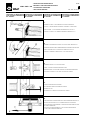
1
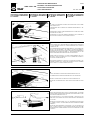
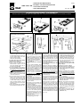
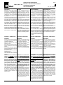
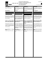
MAINTENANCE 2 VGM • VGR • VG • SLIDE VALVES • FLACHSCHIEBER • VANNES GUILLOTTINE • VALVOLE A GHIGLIOTTINA INSTALLATION, OPERATION AND MAINTENANCE EINBAU -, BETRIEBS - UND WARTUNGSANLEITUNG All rights reserved © WAMGROUP S.p.A INSTALLATION, UTILISATION ET ENTRETIEN CATALOGUE No. ISSUE A6 INSTALLAZIONE, USO E MANUTENZIONE VAL.128.--.M.4L CIRCULATION DATE OF LATEST UPDATE 100 01.10 CREATION DATE 03 - 2000 All the products described in this catalogue are manufactured according to WAMGROUP S.p.A. Quality System procedures. The Company’s Quality System, certified in July 1994 according to International Standards UNI EN ISO 9002 and extended to the latest release of UNI EN ISO 9001, ensures that the entire production process, starting from the processing of the order to the technical service after delivery, is carried out in a controlled manner that guarantees the quality standard of the product. Alle in diesem Katalog beschriebenen Produkte werden gemäß dem Qualitätssystem der WAMGROUP S.p.A. hergestellt. Das im Juli 1994 gemäß der internationalen Norm UNI EN ISO 9002 und auf die neueste Version der UNI EN ISO 9001 erweiterte, zertifizierte Qualitätssystem der Firma gewährleistet, dass der gesamte Produktionsprozess von der Auftragsbearbeitung bis zum technischen Kundendienst nach Lieferung in kontrollierter Art und Weise erfolgt, so dass der Qualitätsstandard des Produkts gewährleistet ist. Tous les produits décrits dans ce catalogue sont fabriqués selon les procédures du Système de Qualité de WAMGROUP S.p.A., certifié en Juillet 1994 selon les normes internationales UNI EN ISO 9002 et étendu à la dernière version de la norme UNI EN ISO 9001. Cela garantit que le processus de production, à partir de la gestion de la commande au service technique après-vente, est effectué de manière contrôlée garantissant la norme de qualité du produit. Tutti i prodotti descritti nel catalogo sono stati realizzati secondo le procedure del Sistema Qualità di WAMGROUP S.p.A. Il Sistema Qualità aziendale, certificato dal luglio 1994 in conformità alle normative internazionali UNI EN ISO 9002 e successivamente esteso all’ ultima versione delle normative UNI EN ISO 9001, garantisce che l’intero processo produttivo, dalla formulazione dell’ordine fino all’assistenza tecnica dopo la consegna, si svolga secondo modalità controllate che garantiscono lo standard qualitativo del prodotto. This publication cancels and replaces any previous edition and revision. We reserve the right to implement modifications without notice. This catalogue cannot be reproduced, even partially, without prior consent. Diese Veröffentlichung storniert und ersetzt alle früheren Ausgaben und überarbeiteten Fassungen. Wir behalten uns das Recht vor, Änderungen ohne vorherige Information durchzuführen. Dieser Katalog darf ohne vorherige Genehmigung weder ganz noch teilweise vervielfältigt werden. Cette publication annule et remplace toute édition et révision antérieure. Nous nous réservons le droit de mettre en place des modifications sans préavis. Ce catalogue ne peut être reproduit, même partiellement, sans notre consentement préalable. Questa pubblicazione annulla e sostituisce le edizioni e revisioni precedenti. Ci riserviamo la facoltà di apportare modifiche senza preavviso. Il presente catalogo non può essere riprodotto, nemmeno parzialmente, senza previo consenso. - INDEX VGM • VGR • VG 3.00 - INHALTSVERZEICHNIS - INDEX - INDICE 2 MAINTENANCE CATALOGUE VAL.128.--.M.4L INDEX WARTUNGSKATALOG OPERATION AND MAINTENANCE.................................................................................... BETRIEBS- UND WARTUNGSANLEITUNG.............................................. M. 01 > .15 2 CATALOGUE D’ENTRETIEN CATALOGO DI MANUTENZIONE UTILISATION ET ENTRETIEN............................................................................................ USO E MANUTENZIONE........................................................................... M. 01 > . 15 - OPERATION AND MAINTENANCE VGM • VGR • VG 2 - UTILISATION ET ENTRETIEN - USO E MANUTENZIONE ADDRESS OF LOCAL DEALER OR SERVICE POINT 01.10 - BETRIEBS - UND WARTUNGSANLEITUNG ANSCHRIFT DES LOKALEN HÄNDLERS ODER KUNDENDIENSTES ADRESSE DU REVENDEUR OU DU SERVICE APRESENTE LOCAL VAL.128.--.M.4L. 01 INDIRIZZO RIVENDITORE O PUNTO DI ASSISTENZA LOCALE IDENTIFIKATION IDENTIFICATION PLAQUE D’IDENTIFICATION INTERPRETAZIONE DELLA - Refer to order code in acknowl- -Zur korrekten Identifikation auf -Pour identifier correctement la TARGHETTA edgement of order, in invoice den Bestellcode in der Auftrags- machine, vous devez vous réfé- -Per una corretta identificazione and on packaging to identify bestätigung, in der Rechnung rer au code qui se trouve sur la della macchina, bisogna fare und auf der Verpackung Bezug confirmation de commande, sur riferimento al codice che si trova equipment. nehmen. la facture et sur la plaque qui se sulla conferma d’ordine, sulla trouve sur l’emballage. fattura e sulla targhetta posta sull’imballo. CONTRA- INDICATIONS - None if all safety instructions are followed. -Check first with supplier when handling acid containing products or particularly hot or cold materials. - VG-type Slide Valves must only be closed with bulk material column in motion. -The valve must not be put into service before the machine or plant it has been fitted to has been declared in conformity with the regulations of the directive 14/06/1982 (89/392/ECC). -It is the plant designer’s / plant fitter’s responsibility to design and install all necessary protection in order to avoid that breaking and/or yielding of the equipment or of parts of it might damage people and/or parts of the plant (e.g. adequate protection against falling down of the motor etc.). KONTRAINDIKATIONEN -Keine, sofern alle allgemeinen Sicherheitsvorschriften befolgt werden. -Bei säurehaltigen sowie bei besonders heißen oder kal ten Medien vor dem Einsatz Rücksprache mit dem Hersteller halten. - Flachschieber vom Typ VG dürfen nur bei in Bewegung befindlicher Materialsäule geschlossen werden. -Der Schieber darf nicht in Betrieb genommen werden, bevor die Anlage oder Maschine, in die er eingebaut wurde mit den Vorschriften der Bestimmungen vom 14.06.1982 (89/392/ECC) als konform erklärt wurden. -Es liegt in der Verantwortung des Anlagenplaners bzw. – aufstellers, alle notwendigen Schutzvorrichtungen vorzusehen, welche es verhindern, dass durch einen Geräte- oder Teiledefekt Personen- und/ oder Sachschäden verursacht werden (z.B. geeigneter Schutz gegen das Herunterfallen des Motors etc.). CONTRE- INDICATIONS POUR L’UTILISATION DE LA VANNE -Il n’existe aucune contre indication pour l’utilisation de la vanne si vous prenez les précautions normales pour les machines de ce genre. - Si le produit qui entre en contact avec la vanne est acide ou bien si sa température est trop élevée ou trop basse, adressez-vous directement à notre service aprés-vente. -Les vannes à guillotine de type VG doivent être fermées seulement avec la colonne de matériau en mouvement. -Il est interdit de mettre en fonction la vanne avant que l’installation dans laquelle elle doit etre installée soit déclarée conforme aux dispositions de la directive 14/06/1982 (89/392/ECC). -Dans ce cadre il est la responsabilité du constructeur de l’installation ou de l’installateur de projeter et d’installer tout équipement de protection nécessaire afin d’éviter que des ruptures et/ou des tassements de la machine et/ou des parties d’elle puissent causer de dégâts à des personnes et/ou des choses (par ex.: des protections appropriées contre la chute du moteur etc.). CONTROINDICAZIONI ALL’USO -Non vi é nessuna controin dicazione all’uso, se vengono osservate le normali precauzioni per macchine di questo tipo. -Nel caso in cui il prodotto a contatto con la valvola sia acido o a temperatura troppo elevata o troppo bassa, rivolgersi direttamente al ns. Uff. Tecnico Commerciale. - Le valvole a ghigliottina tipo VG devono essere chiuse soltanto con colonna di prodotto in movimento. -E’ inoltre vietato metterle in funzione prima che la macchina/impianto nel quale devono essere installate sia dichiarato conforme alle disposizioni della direttiva 14/06/1982 ( 89/392/ECC ). -In quest’ambito è cura dell’impiantista / installatore predisporre ed installare tutti gli accorgimenti / protezioni al fine di evitare danni a cose o persone in caso di rotture e conseguente caduta di pezzi della macchina (ad es: rottura del motore). -For dangerous materials, i.e. those that must not get in contact with the human body or be inhaled, for flammable, explosive and bacteriologically dangerous materials the plant - Für Gefahrenprodukte, bzw. sol-Per prodotti pericolosi, nocivi al manufacturer or fitter must che, die nicht mit dem menschlicontatto e/o all’inalazione, inprovide for the required safety chen Körper in Kontakt geraten fiammabili, esplosivi e pericolosi oder eingeatmet werden dürfen, devices and measures. dal punto di vista batteriologico für leicht entzündbare, explosive e/o virale, l’impiantista e/o l’insowie bakteriologisch gefährlistallatore, dovranno prevedere che Medien muß der Anlagen- -Pour des produits dangereux, idonei dispositivi all’uopo. bauer bzw. –errichter die für nuisibles au contact et/ou à die Sicherheit erforderlichen l’inhalation, inflammables, exVorrichtungen vorsehen und plosifs et dangereux du point de Maßnahmen treffen. vue bactériologique et/ou viral, le constructeur de l’installation ou l’installateur devront prévoir des dispositifs appropriés au besoin. - OPERATION AND MAINTENANCE 01.10 - BETRIEBS - UND WARTUNGSANLEITUNG VGM • VGR • VG 2 - UTILISATION ET ENTRETIEN - USO E MANUTENZIONE VAL.128.--.M.4L. 02 TRANSPORT AND RECEIPT OF GOODS On arrival, prior to unloading, check goods are in compliance with delivery note, invoice and acknowledgement of order. If any parts are damaged through transport immediately state your claims in writing in the consignment note (waybill). The driver is obliged to accept the claim and to leave you a copy. Send off your claim without hesitation to the supplier if you received the goods free destination. In all other cases send claim to shipping agent. If you fail to state your claims on arrival of the goods it may not be accepted. Avoid any kind of damage to goods during unloading and handling. Always handle goods with care. TRANSPORT - WAREN-EMPFANG Bei Wareneingang vor dem Abladen prüfen, ob die Ware in Beschaffenheit und Menge mit den Angaben auf Lieferschein, Rechnung und Auftragsbestätigung übereinstimmt. Eventuelle Schäden sofort schriftlich im Frachtbrief reklamieren, da spätere Ansprüche nicht mehr geltend gemacht werden können. Der Fahrer ist dazu verpflichtet, die Reklamation entgegenzunehmen und dem Empfänger eine Kopie dieser zu überlassen. Bei Lieferung frei Haus Reklamation an den Lieferanten schicken, in allen anderen Fällen an den Spediteur. Beim Abladen Ware nicht beschädigen. Berücksichtigen, daß es sich um mechanische Teile handelt, die mit Vorsicht zu behandeln sind. TRANSPORT - RECEPTION DE LA MARCHANDISE Au moment où vous recevez la marchandise, vérifiez bien que le modèle et la quantité correspondent aux données indiquées sur le bulletin de livraison, sur la facture et sur la confirmation de commande. Si vous constatez des dommages, vous devez immédiatement le faire savoir en l’écrivant dans l’emplacement prévu à cet effet sur la lettre de voiture. Le chauffeur a l’obligation d’accepter votre réclamation et de vous en laisser une copie. Si la fourniture a été livrée franco destination, envoyez-nous votre réclamation, sinon, envoyez-la directement au transporteur. Si vous ne réclamez pas les dommages et intérêts immédiate-ment après avoir reçu la marchandise, votre réclamation risque de ne pas être acceptée. Veillez à ne pas endommager la marchandise durant le déchargement et la manutention. Faites toujours extrêmement attention quand vous la déplacez. PACKAGING DATA KOLLIMASSE UND GEWICHTE EMBALLAGES ET POIDS TRASPORTO - RICEVIMENTO Al ricevimento della merce controllare se la tipologia e la quantità corrispondono con i dati di bolla di consegna, fattura e conferma d’ordine. Eventuali danni devono essere fatti presenti immediatamente per iscritto nell’apposito spazio della lettera di vettura. L’autista è obbligato ad accettare un tale reclamo e lasciarne una copia a Voi. Se la fornitura è franco destino, inviate il Vs. reclamo a noi, altrimenti direttamente allo spedizioniere. Se non richiederete i danni immediatamente all’arrivo della merce, la vostra richiesta potrebbe non essere accolta. Evitate ogni tipo di danneggiamento durante lo scarico e le movimentazioni. Movimentate sempre la merce con cura. IMBALLI E PESI N.B.: The above weights do not N.B.: Die o.a. Gewichte beinhal- N.B.: Les données ci-dessous ne include any additional packaging ten keine zusätzlichen Verpackun- comprennent pas le poids d’un such as pallets or similar. gen wie Paletten o.ä. éventuel emballage supplémentaire (palette ou autre). N.B: I dati sopra riportati non comprendono il peso di un eventuale imballo cumulativo (pallet o altro). No single packaging provided for Keine Einzelverpackung vorge- Aucun emballage individuel prévu Previsto nessun imballo indiviVG and VGR. sehen für VG die VGR. pour VG et VGR. duale per VG e VGR. Weight - Gewichte - Poids - Peso kg Valve - Schieber Vanne - Valvola Type Nominal width - Nennweite - Taille nominale - Grandezza nominale 150 200 250 300 350 400 500 600 700 800 1000 VGM 5 6 8 10 12 15 / / / / / VGR 18 23 30 37 45 50 / / / / / VG / / / / / / 85 110 135 180 240 Packaging dimensions Valve - Schieber Vanne - Valvola Type VGM VerpackungsmaSSe Emballage Incombrements Imballo - Dimensioni Nominal diameter - Nennweite - Diamètre nominale - Diametro nominale 150 200 250 300 350 400 A B C A B C A B C A B C A B C A B C 330 335 120 335 335 120 400 400 120 445 445 120 550 550 142 550 550 142 - OPERATION AND MAINTENANCE VGM • VGR • VG - BETRIEBS - UND WARTUNGSANLEITUNG - UTILISATION ET ENTRETIEN - USO E MANUTENZIONE 01.10 2 VAL.128.--.M.4L. 03 INSTALLATION EINBAU INSTALLATION INSTALLAZIONE The valves have been preas- Die Klappen sind werksseitig Nous fournissons nos vannes déjà Le valvole vengono fornite già sembled and tested at the factory. komplett vormontiert und getestet. équipées et testées. complete e collaudate prima della consegna. PREPARATION Remove packaging. Mount actuator (hand wheel, manual chain actuator, electropneumatic, gear motor, hydraulic or others). WAM ® supplies some of the above-mentioned actuators which have to be bolted on by the customer. With all other actuators ensure no thrust forces weigh on blade shaft. ELECTRICAL AND PNEUMATIC CONNECTIONS Electrical and pneumatic connections must be carried out by qualified personnel ONLY. DISCONNECT MAINS SUPPLY! Check voltage supply corresponds with motor plate data. Follow general safety instructions. SAFETY NOTICE Never introduce hands in the area between valve body and blade when valve is working. Provide for a saftey grille or a hopper above the machine in order to avoid harm to extremities. To avoid harm also at the outlet side, provide a vertical outlet spout or an equivalent system. START-UP Especially with materials which tend to harden or become sticky through longer periods of storage ensure no material is deposited on the shaft passages. In such a case clean the area thoroughly. Start valve operation without material. If valve works correctly add material and proceed with regular operation. VORBEREITUNG Verpackung entfernen. Antrieb ( Handrad, manuell über Kette, elektropneumatisch, elektromotorisch, hydraulisch o.a.) montieren. WAM® liefert einige der vorgenannten Antriebe, deren Anbau mittels Schraubverbindungen erfolgt. Bei Fremdantrieben dürfen keine Axialkräfte auf die Welle des Klappentellers wirken. PREPARATION Enlevez la vanne de son emballage. Montez sur la vanne l’actionneur prévu (manuel à volant, manuel à distance avec poulie à chaîne, pneumatique, électrique, hydraulique, etc.). La société WAM ® construit quelques-uns des actionneurs énumérés ci-dessus et les fournit séparément: ils doivent donc être boulonnés par le client. Si le client désire monter n’importe ELEKTRISCHER UND PNEUMA- quel autre type d’actionneur, il TISCHER ANSCHLUSS doit seulement vérifier qu’il n’y ait Elektrische und pneumatische An- pas d’efforts axiaux sur l’arbre de schlüsse dürfen NUR von Fach- la vanne. personal vorgenommen werden. BRANCHEMENTS ELECSTROMZUFUHR ABSCHAL- TRIQUES ET PNEUMATIQUES Les branchements électriques TEN! et pneumatiques doivent être Kontrollieren, ob Netzspannung exécutés UNIQUEMENT par un mit den Typenschildangaben personnel spécialisé. übereinstimmt. Allgemeine Sicherheitsvorschrif- AVANT D’EFFECTUER N’IMten beachten. PORTE QUELLE OPERATION, DEBRANCHEZ LA MACHINE DU COURANT ELECTRIQUE ! SICHERHEITSHINWEIS Niemals im Betriebszustand Hände in den Bereich zwischen Klap- Avant de brancher votre machine, assurez-vous que le voltage du penkörper und -Teller führen! Über dem Gerät ein fest mon- réseau correspond bien à celui tiertes Schutzgitter oder einen indiqué sur la plaque du moteur. Trichter vorsehen, der so hoch ist, Respectez toujours les consignes daß die Verletzung von Körper- générales de sécurité. extremitäten ausgeschlossen ist. Ebenfalls zur Ausschließung der PRECAUTIONS GENERALES Verletzungsgefahr am Auslauf Ne mettez jamais vos mains entre einen vertikalen Aufsteckstutzen la partie en mouvement et le corps oder ein gleichwertiges System de la vanne quand celle-ci est en marche! vorsehen. Monter au-dessus de la machine une grille de sécurité fixe ou une INBETRIEBNAHME Besonders bei Medien, die durch trémie d’une hauteur suffisante längere Lagerung zum Aushär- pour empêcher des dommages ten neigen oder klebrig werden, les membres d’une personne. sicherstellen, daß sich an den Pour la même raison il est nécesWellendurchgängen kein Mate- saire d’utiliser à la décharge rial abgelagert hat. Ist dies doch un raccordement vertical ou un der Fall, den Bereich gründlich système équivalent. säubern. Schieber zunächst ohne Material- MISE EN MARCHE zugabe in Betrieb nehmen. Wenn Vérifiez qu’il ne reste pas de subsSchieber problemfrei funktioniert, tances étrangères entre la partie Material zugeben und normalen mobile et le corps de la vanne, surtout s’il s’agit de substances Betrieb aufnehmen. dures ou collantes; s’il y en a, nettoyez soigneusement. Quand vous mettez la machine en marche pour la première fois, vous devez le faire sans produit; si tout marche régulièrement, mettez du produit et procédez normalement. PREPARAZIONE Togliere le valvole dall’imballo. Montare sulla valvola l’attuatore previsto (volantino, manuale a distanza con puleggia a catena, pneumatico, elettrico, idraulico ecc.). La ditta WAM® S.p.a. costruisce e fornisce separatamente alcuni dei tipi sopraelencati: vanno imbullonati dal cliente. Se il cliente intende montare qualsiasi altro tipo di attuatore deve soltanto controllare che non vi siano sforzi assiali sull’albero delle valvole. COLLEGAMENTI ELETTRICI E PNEUMATICI I collegamenti elettrici e pneumatici devono essere eseguiti SOLTANTO da personale specializzato. PRIMA DI QUALSIASI OPERAZIONE STACCARE L’ALIMENTAZIONE DI CORRENTE ! Prima del collegamento assicurarsi che il voltaggio di rete coincida con quello indicato sulla targhetta del motore. Seguire sempre le norme generali di sicurezza. PRECAUZIONI GENERALI Mai mettere le mani tra la parte in movimento e il corpo valvola mentre la valvola è in funzione! In ogni caso é necessario che sopra la macchina venga montata una griglia di sicurezza fissa o una tramoggia che sia di altezza sufficiente ad impedire che gli arti di una persona vengano danneggiati. Lo stesso discorso vale per lo scarico: é necessario usare lo scarico verticale o un sistema equivalente. AVVIAMENTO Verificare che sostanze estranee non si siano fermate tra lama e corpo valvola, soprattutto se sono dure o collanti; se così fosse pulire accuratamente. La prima prova di avviamento deve essere fatta senza prodotto; se tutto funziona regolarmente, alimentare con il materiale e procedere normalmente. - OPERATION AND MAINTENANCE VGM • VGR • VG - BETRIEBS - UND WARTUNGSANLEITUNG - UTILISATION ET ENTRETIEN - USO E MANUTENZIONE 01.10 2 VAL.128.--.M.4L.04 INSTRUCTIONS FOR ASSEM- Montageanleitung mit INSTRUCTIONS DE MONTAGE ISTRUZIONI MONTAGGIO CON BLY WITH CMV TYPE HAND- Handrad Typ CMV AVEC VOLANT TYPE CMV VOLANTINO TIPO CMV WHEEL Fig. 1 -Position the valve on a surface - Den Schieber auf eine flache Un- - Placer la vanne sur une table en - Sistemare la valvola su un piano making sure the upper part in terlage legen und sicherstellen, s’assurant que la partie supé- accertandosi che la parte supeview is that indicated in the dass die nach oben zeigende rieure en vue soit celle indiquée riore in vista sia quella indicata in figura. Figure. sichtbare Seite die von der dans la figure. - Insert the spacer, then the hand- Abbildung ist. - Introduire l’entretoise et le volant -Inserire distanziale, volantino wheel with the relative knob in -Abstandhalter, Handrad mit avec la manette dans l’arbre con relativa manopola nell’albero scanalato. the grooved shaft. dem dazugehörigen Griff auf die cannelé. -Close by fitting the washer, nut Keilwelle stecken. - Bloquer avec la rondelle plate, la - Chiudere con rosetta, rondella e and bolt as shown in Fig. 1 - Mit Unterlegscheibe, Beilage rondelle et la vis comme indiqué vite come in figura 1. und Schraube schließen, so dans la figure 1. wie es in der Abbildung 1 zu sehen ist. -Grease the block (See OP- -Den Block schmieren (siehe -Graisser le bloc (Cf. cat. UTILI- -Provvedere all’ingrassaggio del blocchetto (vedi cat. USO E ERATION AND MAINTENANCE Kat. BETRIEB UND WARTUNG SATION ET ENTRETIEN ”I 2”) MANUTENZIONE ”I 2”) catalogue “(I2)”. „I2“). - OPERATION AND MAINTENANCE VGM • VGR • VG 01.10 - BETRIEBS - UND WARTUNGSANLEITUNG 2 - UTILISATION ET ENTRETIEN - USO E MANUTENZIONE VAL.128.--.M.4L. 05 ISTRUZIONI DI MONTAGGIO ISTRUZIONI DI MONTAGGIO ISTRUZIONI DI MONTAGGIO ISTRUZIONI DI MONTAGGIO CON CILINDRO PNEUMATICO CON CILINDRO PNEUMATICO CON CILINDRO PNEUMATICO CON CILINDRO PNEUMATICO SU “VG/VGR” SU “VG/VGR” SU “VG/VGR” SU “VG/VGR” 1 ASSEMBLY FLANGE “1” ONTO PNEUMATIC ACTUATOR USING BOLTS FLANSCH “1” AM PNEUMATIKZYLINDER MIT SCHRAUBEN “7” BEFESTIGEN FIXER LA BRIDE “1” A L’ACTIONNEUR PNEUMATIQUE AVEC LES VIS “7” FISSARE LA FLANGIA “1” AL COMANDO PNEUMATICO MEDIANTE VITI “7” 2 ASSEMBLE THE PNEUMATIC ACTUATOR “G” TO VALVE BODY USING BOLTS “2” PNEUMATIKZYLINDER “G”AM SCHIEBERRAHMEN MIT SCHRAUBEN “2”BEFESTIGEN FIXER L’ACTIONNEUR “G” AU CORPS DE LA VANNE AVEC LES VIS “2” FISSARE IL COMANDO “G” MEDIANTE VITI “2” AL CORPO VALVOLA 3 ASSEMBLE SUPPORT “3” TO ACTUATOR SHAFT GABEL “3” AN DER ZYLINDERSTANGE BEFESTIGEN MONTER SUPPORT “3” SUR LA TIGE FILETEE DE L’ACTIONNEUR PNEUMATIQUE AVVITARE LA FORCELLA “3” SULL’ASTA FILETTATA DEL CILINDRO 4 FASTEN 4 HEXAGON SOCKET SCREWS DIE 4 INNENSECHSKANTSCHRAUBEN FESTZIEHEN SERRER LES 4 VIS SERRARE LE VITI A BRUGOLA CON APPOSITO ATTREZZO 5 OPEN PNEUMATIC CYLINDER COMPLETELY USING COMPRESSED AIR PISTOL “U” MITTELS DRUCKLUFTPISTOLE “U” ZYLINDERSTANGE VOLL AUSFAHREN AVEC UN PISTOLET A AIR COMPRIME “U” FAIRE SORTIR COMPLETEMENT LA TIGE DU VERIN PNEUMATIQUE CON PISTOLA AD ARIA COMPRESSA “U” FAR SFILARE COMPLETAMENTE LO STELO DEL COMANDO PNEUMATICO - OPERATION AND MAINTENANCE VGM • VGR • VG 01.10 - BETRIEBS - UND WARTUNGSANLEITUNG 2 - UTILISATION ET ENTRETIEN - USO E MANUTENZIONE VAL.128.--.M.4L.06 ISTRUZIONI DI MONTAGGIO ISTRUZIONI DI MONTAGGIO ISTRUZIONI DI MONTAGGIO ISTRUZIONI DI MONTAGGIO CON CILINDRO PNEUMATICO CON CILINDRO PNEUMATICO CON CILINDRO PNEUMATICO CON CILINDRO PNEUMATICO SU “VG/VGR” SU “VG/VGR” SU “VG/VGR” SU “VG/VGR” 6 FIT SHAFT OF PNEUMATIC CYLINDER ONTO SLIDE BLADE AND FIX SAME WITH SPECIAL PIN “S” STANGENGABEL DES ZYLINDERS MIT VERRIEGELUNGSELEMENT “S” BEFESTIGEN POSITIONNER LA TIGE DU VERIN PNEUMATIQUE SUR LA LAME DE LA VANNE ET FIXER AVEC LA PIECE “S” POSIZIONARE LO STELO DEL COMANDO PNEUMATICO SULLA LAMA DELLA GHlGLIOTTlNA E FISSARLO CON LA SPECIALE SPINA “S” 7 AFTER FITTING PIN “S” ONTO PNEUMATIC CYLINDER SHAFT, INSERT BOLT “P” WITH 3 WASHERS “R” AND “R1” : FASTEN HEXAGONAL NUT “D” AND SELF LOCKING NUT “DA”. NACH VERBINDUNG DES VERRIEGELUNGSELMENTS “S” MIT ZYLINDERSTANGE DIE 2 STIFTSCHRAUBEN “P” MIT JEWEILS 3 UNTERLEGSCHEIBEN “R” UNTERLEGEN UND IN DIE SEITLICHEN LANGLÖCHER IM SCHIEBERBLECH EINFÜHREN; MIT UNTERLEGSCHEIBE “R1”, SECHSKANTMUTTER “D” UND SELBSTSICHERNDER SECHSKANTMUTTER “DA” BEFESTIGEN. APRES AVOIR FIXE LA PIECE “S” A LA TIGE DU VERIN INSERER LES 2 TOURILLONS “P” SUR LES 3 RONDELLES “R” ET “R1”, SERRER AVEC L’ECROU “D” ET L’ECROU AUTOBLOQUANT “DA”. DOPO AVERE AGGANCIATO LA SPINA “S” ALLO STELO DEL CILINDRO ” CPL” INSERIRE I 2 PERNI A VITE “P” CON LE SUE 3 RONDELLE “R” ED “R1”, SERRARE CON IL DADO “D” E IL DADO AUTOBLOCCANTE “DA”. 8 ADJUST EXTENSION OF SLIDE BLADE USING HEXAGONAL NUT “DE” SCHIEBERANSCHLAG ÜBER SECHSKANTMUTTER “DE” REGULIEREN REGLER LA POSITION DE LA LAME AVEC L’ECROU HEXAGONAL “DE” REGOLARE L’ESTENSIONE DELLA LAMA A GHIGLIOTTINA TRAMITE IL DADO “DE” 9 ADJUST TWO LIMIT SWITCHES “F1” AND “F2” THROUGH SCREW “T” AS SHOWN IN FIGURE. MOBILE BAR MUST BE POSITIONED, AS SHOWN ON SKETCH, ONE CLICK BELOW HORIZONTAL LEVEL “A”. DIE 2 ENDSCHALTER “F1 und F2” ÜBER SCHRAUBE “T” EINSTELLEN; LAUT ABB. MUSS SCHALTHEBEL EINE STUFE UNTERHALB DER HORIZONTALEN “A” STEHEN REGLER LES 3 FINS DE COURSE “F1” ET “F2” EN AGISSANT SUR LE BOULON “T” COMME ILLUSTRE. LE LEVIER MOBILE DEVRA SE PRESENTER COMME INDIQUE “A” REGOLARE OPPORTUNAMENTE I 2 FINE CORSA “F1” ED “F2” AGENDO SULLA VITE “T” COME ILLUSTRATO, LA LEVETTA MOBILE DOVRA’ RISULTARE COME RAPPRESENTATO SCHEMATICAMENTE DI UNO SCATTO ABBASSATA OLTRE IL PIANO “A”. - OPERATION AND MAINTENANCE VGM • VGR • VG 01.10 - BETRIEBS - UND WARTUNGSANLEITUNG 2 - UTILISATION ET ENTRETIEN - USO E MANUTENZIONE VAL.128.--.M.4L. 07 ISTRUZIONI DI MONTAGGIO ISTRUZIONI DI MONTAGGIO ISTRUZIONI DI MONTAGGIO ISTRUZIONI DI MONTAGGIO CON CILINDRO PNEUMATICO CON CILINDRO PNEUMATICO CON CILINDRO PNEUMATICO CON CILINDRO PNEUMATICO SU “VG/VGR” SU “VG/VGR” SU “VG/VGR” SU “VG/VGR” 10 FIT LIMIT SWITCH “F1” AS SHOWN ENDSCHALTER (F1) WIE IN ABB. DARGESTELLT ANBAUEN MONTER LE FIN DE COURSE “F1” COMME INDIQUE APPLICARE IL FINE CORSA “F1” COME INDICATO 11 FIT LIMIT SWITCH “F2” AS SHOWN ENDSCHALTER (F2) WIE IN ABB. DARGESTELLT ANBAUEN MONTER LE FIN DE COURSE “F2” COMME INDIQUE APPLICARE IL FINE CORSA “F2” COME INDICATO 12 COMPLETE VIEW OF CORRECT POSITIONING OF TWO LIMIT SWITCHES KORREKTE EINBAUSITUATION DER ENDSCHALTER VUE TOTALE DE LA POSITION CORRECTE DU POSITIONNEMENT DES 2 FINS DE COURSE VISTA TOTALE DELLA POSIZIONE CORRETTA D’INSTALLAZIONE DEI 2 FINE CORSA - OPERATION AND MAINTENANCE VGM • VGR • VG 01.10 - BETRIEBS - UND WARTUNGSANLEITUNG 2 - UTILISATION ET ENTRETIEN - USO E MANUTENZIONE VAL.128.--.M.4L.08 AR GEAR MOTOR DRIVE ASSEMBLY - AR GETRIEBEMOTOR INSTRUCTION DE MONTAGE AVEC MOTORIDICTEUR AR - ISTRUZIONI DI MONTAGGIO CON MOTORIDUTTORE AR 1 4 1) Put the valve on a solid and smooth surface.The upper part of the valve must be visible.Mount gear motor “A” onto the splined shaft of the valve frame as shown in Fig.1. Fasten two bolt screws “B”. For slide valves from series 500 to 1000 see Fig. 2 and Fig. 3: 2)Remove cover “D” (Fig.2). 3)Insert 2 bolts “B” from inside to external holes on plate “P”. Fix CR gear motor actuator with 2 nuts “C” as shown in sketch Fig.3. 4)Insert bolts M8x25 (S) and washers Ø 12 (R) into slots (K) which allows the adjustment of the stroke of the blade. Fasten bolt on lower side with washer Ø 8 (T) and nuts (U). 5)Put arms of limitswitches (V) at right angle: roller (P) must rest on blade on the side of the hole. 6)Fix with bolts and nuts the limit switches on the plates of the valve body. Open valve position: head of screw (S) has to be positioned on limit switch roller (P). Holes (Y) serve as cable passages. Check functioning and correct connection before start-up. 7)Carry out greasing (see operation and maintenance manual, item “I 2”). 2 3 5 1) Schieberrahmen wird mit bereits montiertem, geschlossenem Schieberblech geliefert. Schieber auf eine feste, glatte Unterlage legen sodaß die im Abb. 1 dargestellte Seite nach oben zeigt. Gegenflansch (B) mittels der zwei Schrauben am Rahmen befestigen. Getriebemotor auf Vielkeilwelle montieren (siehe Abb. 1). Betr.: Schiebergrößen 500 - 1000 (Abb. 2 und 3): 2)Deckel (D) entfernen (Abb. 2). 3)Zwei Schrauben (B) an der Innenseite des Rahmens in die beiden äußeren Bohrungen der Platte (P) einführen und Antrieb mittels der in Abb.3 gezeigten Sechskantmuttern (C) befestigen. 4)Schrauben M8x25 (S) und Unterlegscheiben Ø12 (R) in Langlöcher (K) einführen, welche eine Einstellung der Hublänge der Schieberplatte ermöglichen. Schrauben von unten mit Unterlegscheiben Ø8 (T) und Muttern (U) befestigen. 5)Schwenkhebel der Endschalter (\/) in rechtwinklige Position zur Achse bringen.Die Endschalterhebelrolle (P) muß auf das Schieberblech im Bereich des Langlochs drücken. 6)Endschalter an den Längsstreben des Schiebergehäuses mittels Schrauben und Muttern befestigen. POSITION ”SCHIEBER AUF”: Schraubenkopf (S) wirkt auf die Schwenkhebelrolle (P) des dem Antrieb näher liegenden Endschalters. Die Bohrungen (Y) in den längsseitigen Winkelrahmenblechen des Schiebergehäuses dienen als Durchgang für die Verbindungskabel der Endschalter. Vor dem Einbau Funktion von Schieberblech und Endschaltern prüfen. 7)Nachschmieren (siehe Betriebs- und Wartungsanleitung, Pos. “I 2”). 6 1)Installer la vanne sur un plan de façon à ce que la partie supérieure en vue soit celle indiquée à la Fig.1. Ensuite insérer comme indiqué à la Fig.1, le motoréducteur (A) dans l’arbre cannelé de façon à ce que l’axe du motoréducteur soit horizontal par rapport au sol. Visser les deux vis B et serrer très fort. Pour les vannes modèle 500 à 1000 (Fig. 2 et Fig. 3): 2)Enlever le capuchon (D) (Fig. 2). 3) Effectuer le montage du motoréducteur suivant le schéma de la Fig. 3. 4)Insérer les boulons M8x25 (S) et les rondelles Ø12 (R) dans les bou-tonnières (K) qui permettent le réglage de la course de la lame. Pour la fixation des boulons sur la partie inférieure utiliser les rondelles Ø8 (T) et les écrous (U). 5)Tourner les bras des fins de courses (V) jusqu’à ce qu’ils soient perpendiculaires à l’axe d’eux-mêmes: le galet (P) doit être positionné sur la guilliottine sur la côté du trou. 6)Fixer les fins de courses sur les longerons sur la côté des écrous. Position de vanne ouverte: la tête de la vis (S) doit être positionnée sur le galet (P) du fin de course. Les trous (Y) sont pour sortir le câblage. Vérifier le fonctionnement et le correct branchement des fins de course. 7)Pourvoir au graissage du bloc (voir manuel d’utilisation et d’entretien, pos. “I 2”). 1)Sistemare la valvola su un piano accertandosi che la parte superiore in vista sia quella indicata in figura. L’inserimento del motoriduttore A nell’albero scanalato del corpo valvola va fatto come indicato in Fig.1, cioe’ con l’asse del motoriduttore orizzontale al piano terra. Avvitare le due viti B e serrare forte. Per le valvole serie 500 flno a 1000 (Fig.2 e Fig.3): 2)Togliere il coperchio D (Fig.2). 3)Introdurre dall’interno valvola le 2 viti B nei 2 fori piu’ esterni della piastra P e fissare il moriduttore con i 2 dadi C come in Fig.3. 4)Infilare le viti M8x25 (S) e rondelle Ø12 (R) nelle asole (K), che consentono la registrazione della corsa della lame. Per il fissaggio dei bulloni dalla parte inferiore, utilizzare le rondelle Ø8 (T) e i dadi (U). 5)Portare i braccetti dei finecorsa (V) perpendicolari all’asse degli stessi: la rotella (P), deve disporsi sulla lame dalla parte dell’asola. 6)Fissare i finecorsa sui longheroni del corpo valvola con viti e dadi. Posizione di valvola aperta: testa della vite (S) sulla rotella (P) del finecorsa. Fori (Y) per uscita cablaggi. Verificare funzionalità e consensi fine corsa a banco. 7)Provvedere all’ingrassaggio del blocchetto(vedi cat.USO E MANUTENZIONE “I 2”). - OPERATION AND MAINTENANCE VGM • VGR • VG - BETRIEBS - UND WARTUNGSANLEITUNG - UTILISATION ET ENTRETIEN - USO E MANUTENZIONE 01.10 2 VAL.128.--.M.4L. 09 OPERATION Depending on the type of plant, the valve can be operated either manually, electropneumatically or by a gear motor. In the two latter versions the valve is controlled by a remote control panel or by a local starter. The weight of the material column must not exceed the resistance of the mobile valve parts. Materials with bulk density < 1.3 tons per cubic metre normally do not create any problem. When dealing with materials with higher bulk density check with customer service. N.B.: Regular cleaning increases the life of the valve. This applies in particular to applications where materials are handled which either tend to harden or become sticky when stored for a longer period. BETRIEB Je nach Anlagentyp wird der Schieber entweder von Hand, elektropneumatisch oder elektromotorisch betrieben. In den letzten beiden Versionen wird der Schieber entweder über eine zentrale Steuerung oder über einen Vor‑Ort‑Schaltkasten in Betrieb genommen. Das Gewicht der Materialsäule darf nicht größer sein als der Widerstand der mobilen Schieberteile. Medien mit einem Schüttgewicht < 1.3 t/m³ stellen in der Regel kein Problem dar. Bei Medien mit höherem Schüttgewicht Rücksprache mit dem Kundendienst halten. N.B.: Regelmäßiges Säubern erhöht die Lebensdauer des Schiebers. Dies gilt insbesondere für Medien, die bei längerer Lagerung aushärten oder klebrig werden. FONCTIONNEMENT Suivant le type d’installation, la vanne peut fonctionner manueIIement, pneumatiquement ou électriquement; dans les deux derniers cas, la commande peut se trouver sur un pupitre central ou sur place. II est très important de savoir le poids du produit qui pèse sur la partie mobile de la vanne; il ne doit jamais dépasser la résistance maximum de cette dernière. Pour les silos et les trémies de série avec des produits dont le poids spécifique est inférieur à 1.3 t/m³, il n’y a pas de problémes; dans les autres cas, consultez notre bureau technique. N.B.: Pour augmenter de beaucoup la durée de la vanne, nettoyez‑la régulièrement. Ce nettoyage est particulièrement important si le produit traité a la tendance à se durcir ou à se tasser quand il reste quelque temps immobile. FUNZIONAMENTO In base al tipo di impianto, il funzionamento di una valvola è manuale, pneumatico o elettrico: in questi due ultimi casi il comando può essere o in un quadro centrale o in loco. E’ molto importante conoscere il peso del prodotto che grava sulla parte mobile della valvola: esso non deve mai superare la sua massima resistenza. Con sili e tramogge standard con prodotti di peso specifico inferiore a 1.3 non vi sono problemi); in caso contrario consultare il ns. Uff. Tecnico Commerciale. N.B.: Si aumenta notevolmente la durata della valvola pulendola periodicamente. Questo é particolarmente importante quando il prodotto trattato tende ad indurirsi o a compattarsi se rimane fermo per un certo periodo di tempo. ASSEMBLY / DISMANTLING MONTAGE / DEMONTAGE MONTAGE / DEMONTAGE MONTAGGIO - SMONTAGGIO ASSEMBLY Put the valve in position and bolt it on carefully using nuts, bolts and stud bolts respectively. (Make sure that the valve works perfectly in axis.). Check that it is properly mounted, with the upper part in the correct position. Connect the pneumatic parts to the air line and the electrical parts to the power mains. Ensure the valve is mounted the right way round. Carry out pneumatic und electrical connections in the correct manner. IMPORTANT: For accident prevention it is essential to keep the valve out of reach of personnel during operation. With this aim in mind the customer has to provide suitable safety devices such as grilles, as well as protective inlet and outlet joints (either robust flexible socks or rigid pipe unions). When using movable safety devices provide protection limit switches which stop the valve instantaneously if the protection is opened or removed. Restarting of the valve operation is only possible when the protection is effective again. MONTAGE Schieber in Einbaulage bringen und mittels Schrauben und Muttern gründlich befestigen. Sicherstellen, dass der Schieber perfekt in Achse arbeitet. Sicherstellen, daß der Schieber richtig herum eingebaut ist. Pneumatische und elektrische Anschlüsse vorschriftsmäßig legen. MONTAGE Fixez la vanne à l’endroit prévu en la boulonnant solidement. (Assurez-vous que la vanne fonctionne parfaitement en axe). Vérifiez si elle est montée correctement avec sa partie supérieure dans la bonne position. Branchez les parties pneumatiques à la ligne d’air et les parties électriques au réseau électrique. MONTAGGIO Fissare la valvola, dove è previsto, imbullonandola saldamente. (Accertarsi che la valvola lavori perfettamente in asse). Controllare che sia montata correttamente con la parte superiore nella giusta posizione. Collegare le parti pneumatiche alla linea aria e le parti elettriche alla rete. IMPORTANT: pour respecter les dispositions en vigueur en matière de prévention des accidents, il faut absolument empêcher qu’une main d’homme puisse atteindre l’intérieur de la vanne pendant que celle-ci est en marche. Pour ce faire, la personne qui installe la machine doit prévoir des obstacles tels que des grilles, des filets de protection, etc. et/ou des entretoises, aussi bien pour la partie supérieure que pour la partie inférieure (manchons, etc.) qui en empêchent l’accès. Si ces “protections” sont mobiles, vous devez équiper l’appareil d’un dispositif qui provoque immédiatement l’arrêt de la vanne quand cette protection est retirée ou ouverte. En outre, ce même dispositif ne doit pas permettre que la machine démarre si la protection n’est pas placée dans la bonne position. IMPORTANTE: Per rispettare le vigenti disposizioni in materia di prevenzione è assolutamente da evitare la possibilità che l’interno della valvola in funzione sia raggiungibile da mano d’uomo. Per ottenere ciò, l’installatore deve prevedere ostacoli (griglie, reti di protezione, ecc.) e/o distanziali sia per la parte superiore che per la parte inferiore (calzoni, ecc.) che non permettano l’accesso. Se queste “protezioni” sono mobili, è obbligatorio dotare l’apparecchiatura di un dispositivo che provochi l’immediato arresto della valvola all’atto della rimozione o apertura della protezione. Tale dispositivo inoltre non deve consentire l’avviamento della macchina se la protezione non è collocata nella posizione corretta. WICHTIG: Zur Unfallverhütung unbedingt darauf achten, daß das Betriebspersonal den Schieber im Betriebszustand nicht mit den Händen erreichen kann. Zu diesem Zweck müssen kundenseitig geeignete Schutzvorrichtungen wie z.B. Gitter sowie zu- und abflußseitig geschützte Verbindungen (z.B. robuste flexible Schlauch- oder starre Rohrverbindungen) vorgesehen werden. Bei Verwendung von beweglichen Schutzvorrichtungen sind SchutzEndschalter vorzusehen, die beim Öffnen oder Entfernen der Schutzvorrichtung den Schieber im gleichen Moment außer Betrieb setzen und die neuerliche Inbetriebnahme erst dann ermöglichen, wenn die Schutzvorrichtung wieder wirksam ist. - OPERATION AND MAINTENANCE VGM • VGR • VG - BETRIEBS - UND WARTUNGSANLEITUNG - UTILISATION ET ENTRETIEN - USO E MANUTENZIONE 07.07 /01.10 2 VAL.128.--.M.4L. 10 DISMANTLING DEMONTAGE Prior to dismantling ensure mains Vor Demontage des Schiebers supply is disconnected. oder von Schieberteilen sicherstellen, daß die Stromzufuhr unterbrochen ist. DEMONTAGE Avant de démonter une pièce quelconque de la vanne, assurezvous que cette dernière est bien débranchée du réseau électrique. SMONTAGGIO Prima di smontare qualsiasi pezzo della valvola, assicurarsi che l’alimentazione di corrente sia staccata. MAINTENANCE WARTUNG Failure to follow the main- Das Nichtbefolgen der Wartenance instructions could tungsvorschriften kann zu Stöcause problems and might rungen führen und die Gewährinvalidate the warranty. leistung außer kraft setzen. ENTRETIEN Si vous ne respectez pas exactement les consignes suivantes vous pouvez avoir de graves problèmes et invalider la garantie des machines fournies. MANUTENZIONE Il non attenersi strettamente alle seguenti istruzioni può causare problemi ed invalidare la garanzia sulle macchine fornite. Once a week, check material flows freely and no material deposits spoil the function of the valve. If necessary clean contact parts thoroughly. Toutes les semaines, vérifiez s’il n’y a pas de résidus dans la zone de passage du produit. S’il y en a, nettoyez soigneusement afin d’éviter tout engorgement. Ogni settimana, verificare che la zona di passaggio del materiale sia libera da residui dello stesso: se non lo è, pulire accuratamente per evitare ogni ostruzione. PRIOR TO EVERY MAINTE- VOR JEDER WARTUNGSAR- AVANT D’ENTREPRENDRE NANCE JOB, DISCONNECT BEIT HAUPTSTROMZUFUHR N’ IMPORTE QUELLE OPEVALVE FROM MAINS SUPPLY! UNTERBRECHEN! RATION, DEBRANCHEZ LA VANNE DU RESEAU ELECTRIQUE! Routinely empty the rear casing Den hinteren Gehäuseteil des of the valve to prevent the accu- Flachschiebers regelmäßig lee- Nettoyez périodiquement le boîmulation of powder and allow for ren, um einen Materialrückstaub- tier arrière de la vanne de mathe ducts and the limit switches to zu vermeiden und den freien nière à éviter toute accumulation Fluß der Zu- und Abläufe sowie de poudre encrassante en vue function properly. die Funktion der Endschalter zu d’assurer le bon fonctionnement gewährleisten. des conduits et du fin de course. PRIMA DI QUALSIASI OPERAZIONE STACCARE L’ALIMENTAZIONE DI CORRENTE! REPLACEMENT OF WEAR A U S TA U S C H V O N V E R PARTS SCHLEISSTEILEN No parts replacement required. Es ist kein Teiletausch vorgesehen. ISOSTITUZIONE DEI PEZZI DI USURA Non è prevista nessuna sostituzione di pezzi soggetti ad usura. Einmal wöchentlich sicherstellen, daß das Material frei fließen kann und keine Ablagerungen die Schieberfunktion beeinträchtigen. Ggfls. den produktberührenden Bereich gründlich säubern. REMPLACEMENT DES PIECES USEES Les pièces usées ne seront pas remplacées. Vuotare periodicamente la carcassa posteriore della valvola in modo da evitare ristagno di polvere per permettere il buon funzionamento dei condotti e del fine corsa. - OPERATION AND MAINTENANCE VGM • VGR • VG 01.10 - BETRIEBS - UND WARTUNGSANLEITUNG 2 - UTILISATION ET ENTRETIEN - USO E MANUTENZIONE LUBRICATION No lubrication required. N.B.:only for CRG and AR-type gear motor actuators regular lubrication once every 300 cycles (openings-closings) approximately is recommended. VAL.128.--.M.4L. 11 SCHMIERUNG Keine Schmierung erforderlich. N.B.: Nur für elektromechanische Antriebe vom Typ CRG und AR ist ein Nachschmieren ca. alle 300 Zyklen (Öffnungen und Schliessungen) empfehlenswert. LUBRIFICATION Il n’est prévu aucune lubrification. N.B.: Seulement pour les actionneurs électromécaniques CRG et AR on conseille le cycle de lubrification ordinaire au bloc en bronze toutes les 300 cycles (environ) d’ouverture / fermeture. LUBRIFICAZIONE Nessuna operazione di lubrificazione è prevista. N.B.: unicamente per il comando elettromeccanico AR si consiglia ciclo di lubrificazione ordinaria al blocchetto in bronzo ogni 300 cicli circa apertura/chiusura. NOISE BETRIEBSGERÄUSCHE Noise level depends on handled Intensität der Betriebsgeräumaterial and on actuator type. sche abhängig vom behandelten Schüttgut sowie vom Typ des Schieberantriebs. BRUYANCE Le niveau de bruyance des vannes dépend de la nature du produit dosé et de l’actionneur accouplé. RUMORE Il livello di rumorosità delle valvole dipende dalla natura del materiale dosato e dall’attuatore accoppiato. DISMANTLING AND DISPOSAL Storage of equipment for longer periods Clean equipment thoroughly. Store equipment in a container. Scrapping Recycle plastic materials (e.g. seals, coatings etc.) and dispose according to regulations.Dispose of metal parts at scrap yard. DEMONTAGE UND VERSCHROTTUNG Lagerung des Geräts über längeren Zeitraum Gerät gründlich säubern. Gerät in einem Behälter lagern. Verschrottung Kunststoffteile (z.B. Dichtungen, Beschichtungen etc.) gemäß den Vorschriften recyclen. Metallteile beim Schrotthändler abgeben. DEMONTAGE ET DEMOLITION Mise en entrepôt de la machine pendant une longue période: nettoyez soigneusement la machine; protégez-la en la mettant dans un conteneur. Démontage et mise à la ferraille à la fin de la vie de la machine: récupérez les pièces en matière plastique (par ex. revêtements, joints, etc.) et remettez-les aux centres de récolte spécialisés; remettez les autres pièces, qui sont toutes en acier ou en aluminium, aux centres de récupération des métaux. SMANTELLAMENTO E DEMOLIZIONE Immagazinaggio della macchina per periodo prolungato Pulire accuratamente la macchina. Immagazinare la macchina dentro un contenitore. Rottamazione Riciclare i pezzi in plastica (per es. guarnizioni, rivestimenti etc.) a norma di legge. Consegnare i pezzi in metallo ai centri di raccolta. BETRIEBSSTÖRUNGEN UND FAULT FINDING Minor problems can be resolved ABHILFE Kleinere Störungen können ohne without consulting a specialist. die Einschaltung eines Fachmanns behoben werden. PROBLEMES EVENTUELS Vous pouvez résoudre vousmême les petits problèmes sans devoir consulter un spécialiste. POSSIBILI INCONVENIENTI I problemi minori possono essere risolti senza consultare uno specialista. Item PROBLEM Item REASON Item SOLUTION 1 Valve doesn’t open or 1.1 Material block formed 1.1 Dismantle, clean and stays always open reassemble 1.2 High material 1.2 Provide deflecting weight cone inside container 1.3 Insufficient air 1.3 Check compressed pressure air line 1.4 Drive insufficient 1.4 Check mains supply and gear motor 2 Valve opens and closes 2 Constantly too high 2.1 Check valve works with difficulty material column perfectly in axis 2.2 Slightly lower bearings 2.3 Mount deflecting cone Pos. PROBLEME Pos. CAUSE 1 Vanne ne s’ouvre pas ou1.1 reste toujours ouverte 1.2 Pos. SOLUTION Produit à l’intéreieur 1.1 a formé un bloc Poids élevé du 1.2 produit Démonter, nettoyer et remonter Prévoir un déflecteur de protection 1.3 Pressione d’air 1.3 Contrôler la ligne insuffisante pneumatique 1.4 Puissance motoréduc- 1.4 teur insuffisante 2 Vanne s’ouvre et se 2 Colonne de matériau 2.1 ferme avec difficulté élevéetoujourstravailleenaxe 2.2 Contrôler la ligne élec- trique et motoréducteur Vérifier que vanne Baisser légèrement les roulements 2.3 Positionner déflecteur de protection Pos. STÖRUNG Pos. URSACHE 1 Schieber öffnet nicht 1.1 oder bleibt immer offen 1.2 1.3 1.4 2 Pos. ABHILFE Materialblock im 1.1 Behälterinnern Zu hohes Material- 1.2 gewicht Zu geringer Luftdruck 1.3 Motor zu schwach 1.4 Demontieren, reinigen und wieder montieren Druckentlastungskegel vorsehen Leitung prüfen Hauptleitung und Antrieb prüfen Schieber läßt sich nur 2 schwer öffnen und Ständig zu hohe 2.1 Prüfen, ob Schieber Materialsäule exakt axial arbeitet schließen 2.2 Wälzlager etwas absenken 2.3 Druckentlastungskegel einbauen Pos. PROBLEMA Pos. CAUSA Pos. SOLUZIONE 1 La valvola non si apre o1.1 Il prodotto all’interno 1.1 Smontare, pulire e rimane sempre aperta. ha fatto blocco rimontare 1.2 Elevato peso del 1.2 Prevedere un coppo prodotto di protezione 1.3 La pressione aria è 1.3 Controllare la linea insufficiente pneumatico 1.4 Il motoriduttore è 1.4 Controllare linea elettri- insufficiente ca e motoriduttore 2 La valvola apre e 2 Elevata colonna di 2.1 Verificare che la valvo chiude con fatica materiale sempre la lavori perfettamente presente in asse 2.2 Abbassare leggermente i cuscinetti 2.3 Posizionare coppo di protezione - OPERATION AND MAINTENANCE VGM • VGR • VG 01.10 - BETRIEBS - UND WARTUNGSANLEITUNG 2 - UTILISATION ET ENTRETIEN - USO E MANUTENZIONE List of hazards Gefährdungsliste Liste des risques Lista dei rischi 1. Norm Reference Bezugsnormen Normes de référence Norme di Riferimento Operating Instruction Ref. Bez. Betriebsanleitung Réf. instructions de fonctionnement Rif. istruzioni operative Residual Risk Restrisiken Risque résiduel Rischio residuo Mechanical Hazards - Mechanische Gefährdungenen - Risques mécaniques - Rischi meccanici 1.1 Crushing - Quetschen Ecrasement - Schiacciamento 1.2 Shearing - Scheren Troncature - Troncamento 1.3 Cutting - Schneiden Coupe - Taglio 1.4 Safety Measures Sicherheitsmaßnahmen Consignes de sécurité Misure di sicurezza VAL.128.--.M.4L. 12 Entanglement Erfassen - Aufwickeln Entortillement Attorcigliamento 1.5 Drawing-in - Trapping Einziehen - Fangen Entraînement - Encastrement Trascinamento - Intrappolamento 1.6 Impact - Stoß Impact - Impatto 1.7 Stabbing - puncture Stich Perforation - perçage Perforazione - foratura 1.8 Friction - abrasion Reibung - Abrieb Frottement - abrasion Frizione - abrasione 1.9 High pressure fluid injection Flüssigkeiten unter Druck Injection de fluide à haute pression Iniezione fluido ad alta pressione 1.10 Ejection of parts Ausstoßung von Teilen Ejection des pièces Espulsione di pezzi Protection (grid, robust flexible sock...) to k e e p t he va lve o ut o f r e a c h o f t he personnel. If the protection is movable a limit switch has to be fitted to stop the valve if the protection is removed. Schutzvorrichtungen (Gitter, robuste Verbindungsmanschetten etc.) um zu v e r h i n d e r n ,d a ß d a s Bedienungspersonal mit beweglichen Klappenteilen in Kontakt kommt. Bei beweglichen Schutzvorrichtungen ist ein Endschalter vorzusehen, der die Klappe a b s c h a l t e t ,s o b a l d d i e Schutzvorrichtung entfernt wird. P rotecti on (gri lle, manchon flexi ble robuste etc.) pour éviter que le personnel entre en contact avec les pièces mobiles de la vanne. Si la protection est mobile, un dispositif de fin de course doit être installé qui arrête la vanne au moment où la protection est enlevée. EN 292 - 1 EN 294 EN 349 03020 M.04 NO - NEIN NON - NO EN 292-1 03020 M.04 NO- NEIN NON - NO Protezione (griglia, robusto calzone flessibile ecc...) onde evitare che il personale entri in contatto con le parti mobili della valvola. Con protezioni mobili occorre installare un dispositivo fi ne corsa che arresti l a val vol a al momento in cui la protezione viene rimossa. Not applicable - Nicht anwendbar Non applicable - Non applicabile Fix correctly the machine to the ground or to a strong structure Loss of stability Stabilitätsverlust 1.11 Perte de stabilité Perdita di stabilità Die maschine am Boden oder an e i n e r so l i d e n Stru ktu r ri ch ti g verankern Ancrer correctement la machine au sol ou à une structure solide A ncorare correttam ente l a macchina al suolo o a una struttura solida 1.12 Slip Trip and fall Rutschen oder Fallen Glissement et chute Scivolamento e caduta Not applicable - Nicht anwendbar Non applicable - Non applicabile - OPERATION AND MAINTENANCE VGM • VGR • VG 01.10 - BETRIEBS - UND WARTUNGSANLEITUNG 2 - UTILISATION ET ENTRETIEN - USO E MANUTENZIONE List of hazards Gefährdungsliste Liste des risques Lista dei rischi 2. Safety Measures Sicherheitsmaßnahmen Consignes de sécurité Misure di sicurezza VAL.128.--.M.4L. 13 Norm Reference Bezugsnormen Normes de référence Norme di Riferimento Operating Instruction Ref. Residual Risk Bez. Betriebsanleitung Restrisiken Réf. instructions de Risque résiduel fonctionnement Rischio residuo Rif. istruzioni operative Electrical Hazard - Elektrische Gefährdungen - Risques électriques - Rischi elettrici Minimum protection of terminal box is IP 55 and suitable thermal fuse for the electrical motors has to be fitted. Only qualified personnel has to work on electrical connections. D i e k l e i n s te S c h u tza rt d e r Abzweigdose beträgt IP 55 und für die E l e k tr o m o t o r e n s i n d g e e i g n e t e thermosicherungen zu installieren. D i e e l e ktri sch e n A rb e i te n d ü rfe n ausschließlich durch qualifiziertes Personal ausgeführt werden. 2.1 Electrical contact Elektrischer Kontakt Contact électrique Contatto elettrico La protection minimum du boîtier de dérivation est IP 55 et il faut prévoir des fusibles thermiques appopriés pour les moteurs électriques. L e s o p é r a ti o ns c o nc e r na nt le s raccordements électriques doivent être r é a li s é s e xc lus i ve m e nt p a r d u personnel qualifié. EN 292-1 03020 M.03 03020 M.04 La protezione minima della scatola di derivazione è IP 55 ed è necessario installare adeguati fusibili termici per i motori elettrici. L e o p e ra zi o n i ri g u a rd a n ti i collegamenti elettrici devono essere eseguite esclusivamente da personale qualificato. 2.2 Electrostatic phenomena Elektrostatische Erscheinungen Phénomènes électrostatiques Fenomeni elettrostatici 2.3 Thermal radiation Wärmestrahlung Radiation thermique Radiazione termica 2.4 External influence on equipment Äußere Einwirkungen auf die Geräte Influence extérieure sur les appareillages Influenza esterna sulle apparecchiature 3. 3.1 Not applicable - Nicht anwendbar Non applicable - Non applicabile Thermal Hazards - Thermische Gefährdungen - Risques thermiques - Rischi termici Burns and scalds Verbrennungen und Branwunden Brûlures et lésions Bruciature e ustioni Health -damaging effects by hot/cold environment 3.2 Gesundheitsschädliche Auswirkungen infolge warmer/kalter Umgebungen Effets nocifs pour la santé dus aux environnement chauds/froids Effetti dannosi per la salute dovuti ad ambienti caldi/freddi Not applicable - Nicht anwendbar Non applicable - Non applicabile NO - NEIN NON - NO - OPERATION AND MAINTENANCE VGM • VGR • VG 2 - UTILISATION ET ENTRETIEN - USO E MANUTENZIONE List of hazards Gefährdungsliste Liste des risques Lista dei rischi 01.10 - BETRIEBS - UND WARTUNGSANLEITUNG Safety Measures Sicherheitsmaßnahmen Consignes de sécurité Misure di sicurezza Norm Reference Bezugsnormen Normes de référence Norme di Riferimento VAL.128.--.M.4L.14 Operating Instruction Ref. Residual Risk Bez. Betriebsanleitung Restrisiken Réf. instructions de Risque résiduel fonctionnement Rischio residuo Rif. istruzioni operative 4. Hazard generated by noise - Gefährdungen durch Lärm - Risque dérivant de la pollution acoustique - Rischio da inquinamento acustico Hearing losses Gehörverlust 4.1 Pertes de l'ouïe Perdite dell'udito Not applicable - Nicht anwendbar Non applicable - Non applicabile Interference with speech Verständigungsschwierigkeiten 4.2 Difficulté de communication Difficoltà di comunicazione 5. Hazard generated by vibration - Gefährdungen durch Schwingungen - Risque dû aux vibrations - Rischio dovuto alle vibrazioni Fix correctly the machine to a strong structure Die maschine am Boden oder an einer soliden Struktur richtig verankern NO - NEIN EN 292-1 03020 M.09 Ancrer correctement la machine au NON - NO sol ou à une structure solide Ancorare correttamente la macchina al suolo o a una struttura solida 6. Radiation Hazards - Gefährdungen durch Strahlung - Risques de radiation - Rischi di radiazione Not applicable - Nicht anwendbar Non applicable - Non applicabile Hazards generated by materials processed - Gefährdungen duch die behandelten Materialien 7. Risques dus aux matériaux traités - Rischi dovuti ai materiali trattati For such a kind of materials the plant manufacturer and/or the installator has to fit suitable special device Für diese Art Material ist der Anlagenhersteller oder der Installateurangehalten, passende Fire and explosion Spezialeinrichtungen Brand oder Explosion 7.2 03020 T.01 NO - NEIN bereitzustellen. Incendie et explosion EN 292-1 03020 M.01 NON - NO Pour ce type de matériaux le Incendio ed esplosione constructeur de l'installation ou le personnel responsable est tenu de prévoir des dispositifs spéciaux. Biological (viral/bacterial) Per questo tipo di materiali il Biologisch (durch Viren/Bakterien) 7.3 costruttore dell'impianto o Biologique (viral/bactérien) l'addetto all'installazione è tenuto Biologico (virale/batterico) a predisporre opportuni dispositivi speciali H.generated by neglecting ergonomic principles - Gefährdungen durch die Nichtbeachtung der ergonomischen Richtlinien 8. Risques dus à l'inobservation des principes ergonomiques - Rischi dovuti all'inosservanza dei principi ergonomici Not applicable - Nicht anwendbar Non applicable - Non applicabile 9. Hazards combination - Kombination der Gefährdungen - Combinaison de risques - Combinazione di rischi Contact or inhalation Berühren oder Einatmen 7.1 Contact ou inhalation Contatto o inalazione 10. 10.1 10.2 10.3 10.4 11. Not applicable - Nicht anwendbar Non applicable - Non applicabile H. generated by failure of energy supply - Gefährdungen durch eine Störung der Energieversorgung Risques produits par une panne du secteur d'alimentation - Rischi generati da un guasto nella rete di alimentazione Failure of energy supply Störung im Versorgungsnetz Panne dans le secteur d'alimentation Guasto nella rete di alimentazione Unexpected ejection of parts Unerwartetes Ausstoßen von Teilen Ejection inattendue de pièces Not applicable - Nicht anwendbar Espulsione inaspettata di pezzi Non applicable - Non applicabile Failure of control system Störung des Steuersystems Avarie du système de contrôle Avaria del sistema di controllo Errors of fitting - Passungsfehler Erreurs d'accouplement - Errori di accoppiamento H. generated by missing of safety related measures - Gefährdungen durch die Nichtbeachtung der entsprechenden Sicherheitsnaßnahmen Risques dus à l'absence de mesures concernant la sécurité - Rischi dovuti alla mancanza di misure legate alla sicurezza Not applicable - Nicht anwendbar Non applicable - Non applicabile - OPERATION AND MAINTENANCE VGM • VGR • VG - BETRIEBS - UND WARTUNGSANLEITUNG - UTILISATION ET ENTRETIEN - USO E MANUTENZIONE 01.10 2 VAL.128.--.M.4L. 15 INSTALLED SLIDE VALVE WITH MIT RADIAL ZUR SCHNECKE MONTAGE VANNE AVEC OU- VA LV O L A M O N TATA C O N RADIAL OPENING TOWARDS STEHENDER ÖFFNUNG IN- VERTURE RADIALE A LA VIS APERTURA RADIALE ALLA THE CONVEYOR STALLIERTES VENTIL SAN FIN COCLEA INSTALLED SLIDE VALVE WITH MIT IN LÄNGSRICHTUNG ZUR MONTAGE VANNE AVEC OU- VA LV O L A M O N TATA C O N LONGITUDINAL OPENING TO- SCHNECKE STEHENDER ÖFF- VERTURE LONGITUDINALE A APERTURA LONGITUDINALE ALLA COCLEA WARDS THE CONVEYOR NUNG INSTALLIERTES VENTIL LA VIS SANS FIN The signalling system FNC7 is constituded by a base and 2 limit switches according to CENELEC EN 50041 norms. Das Meldesystem FNC 7 besteht aus einer Basis und 2 Endschaltern, die der Norm CENELEC EN 50041 entsprechen. Le système de signalisation FNC 7 est constitué d’une base et 2 fin de course aux normes CENELEC EN 50041. Il sistema di segnalazione FNC 7 è costituito da una base e 2 finecorsa a norme CENELEC EN 50041. The manual slide valve can be installed in the 4 positions respect to the conveyor with radial or longitudinal opening, right or left. In order to install a manual slide valve an outlet XBQ is required. Der von Hand zu betätigende Schieber kann im Bezug zur Schnecke mit 4 verschiedenen Positionen montiert werden: mit Öffnung auf der radialen Wandung oder der Längsseite, rechts oder links. Um einen von Hand zu betätigenden Schieber installieren zu können, braucht man immer einen Stutzen vom Typ XBQ. La vanne guillotine manuelle peut être montée dans les 4 positions par rapport à la vis sans fin, avec ouverture longitudinale ou radiale, droite ou gauche. Pour installer une vanne guillotine manuelle il faut que la trappe soit toujours de type XBQ. La valvola a ghigliottina manuale può essere montata nelle 4 posizioni rispetto alla coclea, con apertura longitudinale o radiale, destra o sinistra. Per poter installare una valvola a ghigliottina manuale occorre sempre una bocca del tipo XBQ. - DECLARATION OF CONFORMITY VGM • VGR • VG 01.10 - KONFORMITÄTSERKLÄRUNG 2 - DECLARATION DE CONFORMITE - DICHIARAZIONE DI CONFORMITA’ WA.03020.M. 29 Powder Handling - Dust Filtration - Flow Control - Components The manufacturer: WAMGROUP S.p.A. located in Strada degli Schiocchi, 12 - I-41100 Modena (Mo) - Italy under its own responsibility declares that: VG VL Declaration Of Incorporation Of Partly Completed Machinery Annex II B 2006/42/CE Directive comply with the RES Directive 2006/42/EC of the European Parliament and the Council of 17 May 2006 on machinery 1.1.1. - Definitions 1.1.2. - Principles of safety integration 1.1.3. - Materials and products 1.1.5. - Design of machinery to facilitate its handling 1.3.1. - Risk of loss of stability 1.3.2. - Risk of break-up during operation 1.3.3. - Risks due to falling or ejected objects 1.3.4. - Risks due to surfaces, edges or angles 1.3.7. - Risks related to moving parts 1.3.8. - Choice of protection against risks arising from moving parts 1.3.9. - Risks of uncontrolled movements 1.5.4. - Errors of fitting 1.5.5. - Extreme temperatures 1.5.6. - Fire 1.5.7. - Explosion 1.5.8. - Noise 1.5.9. - Vibrations 1.5.13. - Emissions of hazardous materials and substances 1.5.15. - Risk of slipping, tripping or falling 1.6.1. - Machinery maintenance 1.6.2. - Access to operating positions and servicing points 1.6.4. - Operator intervention 1.6.5. - Cleaning of internal parts 1.7.1. - Information and warnings on the machinery 1.7.2. - Warning of residual risks 1.7.4. - Instructions and, where applicable, the requirements imposed by the following EC Directives Directive 2004/108/EC of the European Parliament and the Council of 15 December 2004 on the approximation of the laws of the Member States relating to electromagnetic compatibility. Directive 2006/95/EC of the European Parliament and the Council of 12 December 2006 on the approximation of the laws of the Member States relating to electrical equipment designed for use within certain voltage limits. The relevant technical documentation is compiled in accordance with Annex VII B of the Machinery Directive 2006/42/EC Harmonized standards, national standards and technical regulations in question: EN ISO 12100-1: 2005 EN ISO 12100-2: 2005 The signing company is committed to provide, in response to a reasoned request by national authorities, relevant information on products covered by this declaration, without prejudice to the rights of intellectual property of the manufacturer. The information will be transmitted directly to the national authorities having requested. It’s forbidden to operate all these products before the machine, in which they will be installed, is declared in conformity with 2006/42/EEC AND SUBSEQUENT AMENDMENTS Strada degli Schiocchi, 12 - I-41100 Modena (Mo) - Italy, 01.01.2010 The person authorized to provide the technical documentation: Vainer Marchesini WAMGROUP S.p.A. - Strada degli Schiocchi, 12 - I-41100 Modena (Mo) - Italy The legal representative: Vainer Marchesini - DECLARATION OF CONFORMITY VGM • VGR • VG 01.10 - KONFORMITÄTSERKLÄRUNG 2 - DECLARATION DE CONFORMITE - DICHIARAZIONE DI CONFORMITA’ WA.03020.M. Powder Handling - Dust Filtration - Flow Control - Components Der Hersteller: WAMGROUP S.p.A. mit Sitz in Strada degli Schiocchi, 12 - I-41100 Modena (Mo) - Italien erklärt unter eigener Verantwortung wie folgt: VG VL EINBAUERKLÄRUNG für unvollständige Maschinen gem. Anhang II B der MRL 2006/42/EG Diese Produkte entsprechen den Anforderungen der Maschinenrichtlinie 2006/42/EG des europäischen Parlamentes und des Rates vom 17. Mai 2006 1.1.1. - Begriffsbestimmungen 1.1.2. - Grundsätze für die Integration der Sicherheit 1.1.3. - Materialien und Produkte 1.1.5. - Konstruktion der Maschine im Hinblick auf die Hanhabung 1.3.1. - Risiko des Verlustes der Standsicherheit 1.3.2. - Bruchrisiko beim Betrieb 1.3.3. - Risiken durch herabfallende oder herausgeschleuderte Gegenstände 1.3.4. - Risiken durch Oberflächen, Kanten und Ecken 1.3.7. - Risiken durch bewegliche Teile 1.3.8. - Wahl der Schutzeinrichtungen gegen Risiken durch bewegliche Teile 1.3.9. - Risiko unkontrollierter Bewegungen 1.5.4. - Montagefehler 1.5.5. - Extreme Temperaturen 1.5.6. - Brand 1.5.7. - Explosion 1.5.8. - Lärm 1.5.9. - Vibrationen 1.5.13. - Emission gefährlicher Werkstoffe und Substanzen 1.5.15. - Ausrutsch-, Stolper- und Sturzrisiko 1.6.1. - Wartung der Maschine 1.6.2. - Zugang zu den Bedienungsständen und den Eingriffspunkten für die Instandhaltung 1.6.4. - Eingriffe des Bedienungspersonals 1.6.5. - Reinigen innen liegender Maschinenteile 1.7.1. - Informationen und Warnhinweise an der Maschine 1.7.2. - Warnung vor Restrisiken 1.7.4. - Betriebsanleitung Wo anwendbar wurden die Anforderungen folgender EG Richtlinien erfüllt Richtlinie 2004/108/EG des Europäischen Parlaments und des Rates vom 15. Dezember 2004 zur Angleichung der Rechtsvorschriften der Mitgliedstaaten über die elektromagnetische Verträglichkeit. Richtlinie 2006/95/EG des Europäischen Parlaments und des Rates vom 12. Dezember 2006 zur Angleichung der Rechtsvorschriften der Mitgliedstaaten betreffend elektrische Betriebsmittel zur Verwendung innerhalb bestimmter Spannungsgrenzen. Die speziellen technischen Unterlagen gem. Anhang VII B der MRL 2006/42/EG wurden erstellt. Folgende harmonisierte Normen, nationale Normen und technische Vorschriften fanden Anwendung: EN ISO 12100-1: 2005 EN ISO 12100-2: 2005 Das ausstellende Unternehmen ist verpflichtet, die technischen Unterlagen für diese Produkte auf begründetes Verlangen den Marktaufsichtsbehörden, unbeschadet der Rechte am geistigen Eigentum des Herstellers, zur Verfügung zu stellen. Die Unterlagen werden direkt an die anfordernde Behörde gesandt. Es ist verboten diese Produkte in Betrieb zu nehmen, bevor die Maschine, in welche diese eingebaut werden, den Anforderungen der MRL entspricht und die EG Konformitätserklärung gem. MRL 2006/42/EG und nachfolgenden Änderungen vorliegt. Strada degli Schiocchi, 12 - I-41100 Modena (Mo) - Italien, 01.01.2010 Bevollmächtigter für die Zusammenstellung der relevanten Technischen Unterlagen: Vainer Marchesini WAMGROUP S.p.A. - Strada degli Schiocchi, 12 - I-41100 Modena (Mo) - Italien Für den Hersteller: Vainer Marchesini - DECLARATION OF CONFORMITY VGM • VGR • VG 01.10 - KONFORMITÄTSERKLÄRUNG 2 - DECLARATION DE CONFORMITE - DICHIARAZIONE DI CONFORMITA’ WA.03020.M. Powder Handling - Dust Filtration - Flow Control - Components Le fabricant: WAMGROUP S.p.A. son siège social à Strada degli Schiocchi, 12 - I-41100 Modena (Mo) - Italie déclare sous sa propre responsabilité que les machines type VG VL Déclaration d’Incorporation des machines partiellement construites - Directive 2006/42/CE Annexe II B sont en conformité avec la Directive RES 2006/42/EC du Parlement Européen et du conseil du 17 mai 2006 sur les machines 1.1.1. - Definitions 1.1.2. - Principes d’intégration en sécurité 1.1.3. – Matériels et produits 1.1.5. – Conception des machines pour faciliter leur manipulation 1.3.1. – Risque de perte de stabilité 1.3.2. – Risque de casse pendant fonctionnement 1.3.3. – Risques causés par la chute ou l’éjection d’objets 1.3.4. – Risques liés aux surfaces, aux bords et aux angles 1.3.7. – Risques liés aux pièces en mouvement 1.3.8. – Choix de protection contre les risques résultant de pièces mobiles 1.3.9. – Risques de mouvements non désirés 1.5.4. – Erreurs de montage 1.5.5. – Températures extrêmes 1.5.6. – Feu 1.5.7. – Explosion 1.5.8. – Bruit 1.5.9. – Vibrations 1.5.13. – Emission de matières et substances dangereuses 1.5.15. – Risque de glisser, trébucher ou tomber 1.6.1. – Maintenance des machines 1.6.2. – Accès aux postes de travail et aux points d’intervention 1.6.4. – Intervention de l’opérateur 1.6.5. – Nettoyage des parties internes 1.7.1. – Informations et avertissements sur la machine 1.7.2. – Avertissements sur les risques résiduels 1.7.4. – Notices de fonctionnement et, quand applicable, avec les exigences imposées par les directives européennes suivantes La Directive 2004/108/CE du Parlement européen et du Conseil du 15 Décembre 2004 sur le rapprochement des législa tions des États membres concernant la compatibilité électromagnétique. La Directive 2006/95/CE du Parlement européen et du Conseil du 12 Décembre 2006 sur le rapprochement des législations des États membres concernant le matériel électrique destiné à être employé dans certaines limites de tension. La documentation technique appropriée est constituée conformément à l’annexe VII B de la Directive Machines 2006/42/CE Les normes harmonisées, les normes et règles techniques nationales en question: EN ISO 12100-1: 2005 EN ISO 12100-2: 2005 La société signataire s’engage à fournir, en réponse à une demande motivée par les autorités nationales, toute information sur les produits couverts par cette déclaration, sans préjudice des droits de propriété intellectuelle du fabricant. Les informations seront transmises directement aux autorités nationales demanderesses. Il est interdit d’utiliser tous ces produits avant que la machine, dans laquelle ils seront installés, soit déclarée conforme à la Directive 2006/42/CEE et ses amendements successifs. Strada degli Schiocchi, 12 - I-41100 Modena (Mo) - Italie, 01.01.2010 La personne autorisée à fournir la documentation technique: Vainer Marchesini WAMGROUP S.p.A. - Strada degli Schiocchi, 12 - I-41100 Modena (Mo) - Italie Le représentant légal: Vainer Marchesini - DECLARATION OF CONFORMITY VGM • VGR • VG 01.10 - KONFORMITÄTSERKLÄRUNG 2 - DECLARATION DE CONFORMITE - DICHIARAZIONE DI CONFORMITA’ WA.03020.M. Powder Handling - Dust Filtration - Flow Control - Components Il sottoscritto fabbricante: WAMGROUP S.p.A. con sede legale in Strada degli Schiocchi, 12 - I-41100 Modena (Mo) - Italia dichiara sotto la propria responsabilità che: le quasi macchine serie VG VL ai sensi dell’Allegato II B della Direttiva Macchine 2006/42/CE (DICHIARAZIONE DI INCORPORAZIONE) risultano conformi ai RES della Direttiva 2006/42/CE del Parlamento Europeo e del Consiglio del 17 maggio 2006 relativa alle macchine 1.1.1. - Definizioni 1.1.2. - Principi di integrazione della sicurezza 1.1.3. - Materiali e prodotti 1.1.5. - Progettazione della macchina ai fini della movimentazione 1.3.1. - Rischio di perdita di stabilità 1.3.2. - Rischio di rottura durante il funzionamento 1.3.3. - Rischi dovuti alla caduta o alla proiezione di oggetti 1.3.4. - Rischi dovuti a superfici, spigoli ed angoli 1.3.7. - Rischi dovuti agli elementi mobili 1.3.8. - Scelta di una protezione contro i rischi dovuti agli elementi mobili 1.3.9. - Rischi di movimenti incontrollati 1.5.4. - Errori di montaggio 1.5.5. - Temperature estreme 1.5.6. - Incendio 1.5.7. - Esplosione 1.5.8. - Rumore 1.5.9. - Vibrazioni 1.5.13. - Emissioni di materie e sostanze pericolose 1.5.15. - Rischio di scivolamento, inciampo o caduta 1.6.1. - Manutenzione della macchina 1.6.2. - Accesso ai posti di lavoro e ai punti d’intervento utilizzati per la manutenzione 1.6.4. - Intervento dell’operatore 1.6.5. - Pulitura delle parti interne 1.7.1. - Informazioni e avvertenze sulla macchina 1.7.2. - Avvertenze in merito ai rischi residui 1.7.4. - Istruzioni e, qualora applicabili, alle esigenze imposte dalle seguenti Direttive Comunitarie Direttiva 2004/108/CE del Parlamento Europeo e del Consiglio del 15 dicembre 2004 concernente il riavvicinamento delle legislazioni degli Stati membri relative alla compatibilità elettromagnetica. Direttiva 2006/95/CE del Parlamento Europeo e del Consiglio del 12 dicembre 2006 concernente il riavvicinamento delle legislazioni degli Stati membri relative al materiale elettrico destinato ad essere adoperato entro taluni limiti di tensione. La documentazione tecnica pertinente è stata compilata in conformità dell’Allegato VII B della Direttiva Macchine 2006/42/CE Norme armonizzate, norme nazionali e regole tecniche considerate: UNI EN ISO 12100-1: 2005 UNI EN ISO 12100-2: 2005 L’azienda firmataria della presente si impegna a trasmettere, in risposta a una richiesta adeguatamente motivata delle autorità nazionali, informazioni pertinenti sui prodotti oggetto della presente dichiarazione, fatti salvi i diritti di proprietà intellettuale del fabbricante. Le informazioni verranno trasmesse direttamente all’autorità nazionale che le ha richieste. AVVERTENZA IMPORTANTE. E’ vietato mettere in servizio la quasi macchina oggetto della presente dichiarazione finché la macchina finale in cui deve essere incorporata non è stata dichiarata conforme, se del caso, alle disposizioni della Direttiva Macchine 2006/42/CE. Strada degli Schiocchi, 12 - I-41100 Modena (MO) - Italia, 01.01.2010 La persona autorizzata a costituire il fascicolo tecnico: Vainer Marchesini WAMGROUP S.p.A. - Strada degli Schiocchi, 12 - I-41100 Modena (MO) - Italia Il rappresentante legale: Vainer Marchesini N.B. Rights reserved to modify technical specifications N.B. Angaben ohne Gewähr. Änderungen können ohne Vorankündigung vorgenommen werden. N.B. Toutes données portées dans le présent catalogue n’engagent pas le fabricant. Elles peuvent être modifiéès à tout moment. N.B. Tutti i dati riportati nel presente catalogo non sono impegnativi e possono subire variazioni in qualsiasi momento. WAMGROUP S.p.A. Via Cavour, 338 I - 41030 Ponte Motta Cavezzo (MO) - ITALY fax e-mail internet videoconferenze +39 / 0535 / 618111 +39 / 0535 / 618226 [email protected] www.wamgroup.com + 39 / 0535 / 49032


![Manuell [de]](http://vs1.manualzilla.com/store/data/006725503_1-3df358c510eb69f98248cf7fd2c2e04d-150x150.png)