1
848-C3A-93A0 (410)
OWNER / OPERATOR MANUAL
CHAINSAWS
G3200
G3200EZ
WARNING
WARNING
The engine exhaust from this product
contains chemicals known to the State
of California to cause cancer, birth
defects or other reproductive harm.
Before using our products, please
read this manual carefully to
understand the proper use of your
unit.
APPLICABLE SERIAL NUMBERS :
G3200 : 404766 and up
G3200EZ : 400001 and up
SAFETY FIRST
Instructions contained in warnings within this
manual marked with a
symbol concern
critical points which must be taken into
consideration to prevent possible serious
bodily injury, and for this reason you are
requested to read all such instructions
carefully and follow them without fail.
■ WARNINGS IN THE MANUAL
WARNING
This mark indicates instructions which must be
followed in order to prevent accidents which could
lead to serious bodily injury or death.
IMPORTANT
This mark indicates instructions which must be
followed, or it leads to mechanical failure,
breakdown, or damage.
NOTE
This mark indicates hints or directions useful in the
use of the product.
1.
2.
3.
4.
5.
6.
7.
8.
9.
10.
11.
12.
13.
CONTENTS
Parts location …………………………………4
Specifications …………………………………4
Symbols on the machine ……………………5
For safe operation ……………………………6
Installing guide bar and saw chain …………8
Fuel and chain oil ……………………………11
Operation ……………………………………13
Sawing ………………………………………17
Maintenance …………………………………20
Maintenance of Saw Chain and Guide Bar ………23
Troubleshooting Guide ……………………25
Storage ………………………………………26
Parts list ………………………………………27
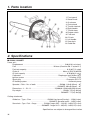
1. Parts location
1. Front guard
2. Starter knob
3. Air cleaner
4. Choke knob
5. Throttle interlock
6. Right handle
7. Throttle lever
8. Engine switch
9. Fuel tank
10. Oil tank
11. Left handle
12. Saw chain
13. Guide Bar
2. Specifications
■ G3200 / G3200EZ
Power unit :
Displacement ···················································································· 2.00(31.8) cu-in(cm3)
Fuel ············································································ Mixture (Gasoline 50 : 2-cycle oil 1)
Fuel tank capacity ················································································· 9.13(0.27) fl.oz( )
Chain oil ························································································ Motor oil SAE #10W-30
Oil tank capacity ···················································································· 6.76(0.20) fl.oz( )
Carburetor ··········································································· Diaphragm type (Walbro WT)
lgnition system ··························································································· Pointless (CDI)
Spark plug ···························································································· Champion RCJ-7Y
Oil feeding system ···················································································· Automatic pump
Sprocket : Pitch – No. of teeth ·············································· G3200: 1/4in(6.35mm) – 8T
·········································· G3200EZ: 3/8in(9.53mm) – 6T
Dimensions : L – W – H ··············································· 15(380)x9.1(230)x9.8(250) in(mm)
Dry weight ····················································································· G3200: 7.5(3.4) lbs(kg)
················································································· G3200EZ: 7.7(3.5) lbs(kg)
Cutting attachment :
Guide bar : Type – Size ································ G3200: Hard nose(Carving) – 12(30) in(cm)
····································· G3200EZ: Sprocket nose – 14(35) in(cm)
Saw chain : Type – Pitch – Gauge ·············· G3200: Oregon 25AP – 1/4(6.35) – 0.050(1.27) in(mm)
········· G3200EZ: Oregon 91VG – 3/8(9.53) – 0.050(1.27) in(mm)
Specifications are subject to change without notice.
4
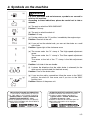
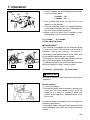
3. Symbols on the machine
WARNING
For safe operation and maintenance, symbols are carved in
relief on the machine.
According to these indications, please be careful not to take a
mistake.
(a). The port to refuel the "MIX GASOLINE"
Position: Fuel cap
(b). The port to refuel the chain oil
Position: Oil cap
(c). Put the switch to the "O" position, immediately the engine stops.
Position: Rear-left of the unit
(d). If you pull out the choke knob, you can set the choke as a cold
start mode.
Position: Upper-right of the aircleaner cover
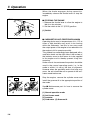
(e). The screw under the "H" stamp is The High-speed adjustment
screw.
The screw under the "L" stamp is The Slow-speed adjustment
screw.
The screw at the left of the "T" stamp is the Idle adjustment
screw.
Position: Left side of the rear handle
(f). It shows the directions that the chain brake is released (for the
white arrow) and activated (for the black arrow).
Position: Front of the chain cover
(g) If you turn the rod by screwdriver follow the arrow to the "MAX"
position, the chain oil flow more, and if you turn to the "MIN"
position, less.
Position: Bottom of the power unit
IMPORTANT ENGINE INFORMATION
T H I S E N G I N E C O N F O R M S TO U S E PA
PH1 FOR SMALL OFF-ROAD ENGINES.
ENGINE FAMILY : 4KZXS. 0324RS:EM
ENGINE DISPLACEMENT : 32cc
REFER TO OWNER'S MANUMAL FOR MAINTENANCE SPECIFICATIONS AND ADJUSTMENTS.
MANUFACTURED :
RedMax
Made in Japan
INFORMATION IMPORTANTE CONCERNANT LE MOTEUR
Ce moteur conformc aux normcs U.S. EPA
PH1 pour les petits moteurs tout-terrain.
Type de moteur : 4KZXS. 0324RS:EM
Cylindrée du moteur : 32cc
Se référer au Manuel de l'utilisateur pour les
spécifications d'entretien et les réglages.
Manufacturé :
RedMax
Made in Japan
5
4. For safe operation
1. Never operate a chain saw when you are
fatigued, ill, or upset, or under the
influence of medication that may make
you drowsy, or if you are under the
influence of alcohol or drugs.
2. Use safety footwear, snug fitting clothing
and eye, hearing and head protection
devices.
3. Select flat and bare ground for fueling.
4. Always use caution when handling fuel.
Wipe up all spills and then move the
chain saw at least ten(10) feet(three(3)
m) from the fueling point before starting
the engine.
4a) Eliminate all sources of sparks or
flame (ie. smoking, open flames, or
work that can cause sparks) in the
areas where fuel is mixed, poured, or
stored.
4b) Do not smoke while handling fuel or
while operating the chain saw.
5. Do not allow other persons to be near
the chain saw when starting the engine
or cutting a wood. Keep bystanders and
animals out of the work area. Children,
pets, and bystanders should be a
minimum of thirty(30) feet away when
you start or operate the chain saw.
6. Never start cutting until you have a clear
work area, secure footing, and planned
retreat path from the falling tree.
7. Always hold the chain saw firmly with
both hands when the engine is running.
Use a firm grip with thumb and fingers
encircling the chain saw handles.
8. Keep all parts of your body away from
the saw chain when the engine is
running.
6
9. Before you start the engine, make sure
the saw chain is not contacting anything.
10. Always carry the chain saw with the
engine stopped, the guide bar and saw
chain to the rear, and the muffler away
from your body.
11. Always inspect the chain saw before
each use for worn, Ioose, or changed
parts. Never operate a chain saw that is
damaged, improperly adjusted, or is not
completely and securely assembled. Be
sure that the saw chain stops moving
when the throttle control trigger is
released.
12. All chain saw service, other than the
items listed in the Operator’s Manual,
should be performed by competent chain
saw service personnel. (e.g., if improper
tools are used to remove the flywheel, or
if an improper tool is used to hold the
flywheel in order to remove the clutch,
structural damage to the flywheel could
occur which could subsequently cause
the flywheel to disintegrate).
13. Always shut off the engine before setting
it down.
14. Use extreme caution when cutting small
size brush and saplings because slender
material may catch the saw chain and be
whipped toward you or pull you off
balance.
15. When cutting a limb that is under
tension, be alert for spring back so that
you will not be struck when the tension in
the wood fibers is released.
16. Keep the handles dry, clean and free of
oil or fuel mixture.
4. For safe operation
17. Operate the chain saw only in well
ventilated areas. Never start or run the
engine inside a closed room or building.
Exhaust fumes contain dangerous
carbon monoxide.
18. Do not operate a chain saw in a tree
unless specially trained to do so.
20. When transporting your chain saw, make
sure the appropriate guide bar scabbard
is in place.
21. This chain saw is equipped with a spark
arrester built-in muffler. Periodically
check the arrester to keep it in good
order.
19. Guard against kickback. Kickback is the
upward motion of the guide bar which
occurs when the saw chain at the nose
of the guide bar contacts an object.
Kickback can lead to dangerous loss of
control of the chain saw.
KICKBACK SAFETY PRECAUTIONS FOR
CHAIN SAW USERS
WARNING
● Kickback may occur when the nose or tip of the guide bar touches an object, or when the
wood closes in and pinches the saw chain in the cut. Tip contact in some cases may
cause a lightning fast reverse reaction, kicking the guide bar up and back towards the
operator. Pinching the saw chain along the top of the guide bar may push the guide bar
rapidly back towards the operator. Either of these reactions may cause you to lose
control of the saw which could result in serious personal injury.
● Do not rely exclusively on the safety devices built into your saw. As a chain saw user you
should take several steps to keep cutting jobs free from accident or injury.
(1) With a basic understanding of kickback you can reduce or eliminate the element of
surprise. Sudden surprise contributes to accidents.
(2) Keep a good grip on the saw with both hands, the right hand on the rear handle, and
the left hand on the front handle, when the engine is running. Use a firm grip with
thumbs and fingers encircling the chain saw handles. A firm grip will help you reduce
kickback and maintain control of the saw. Don’t let go.
(3) Make certain that the area in which you’re cutting is free from obstructions. Do not let
the nose of the guide bar contact a log, branch, or any other obstruction which could
be hit while you are operating the saw.
(4) Cut at high engine speeds.
(5) Do not overreach or cut above shoulder height.
(6) Follow manufacturers sharpening and maintenance instructions for saw chain.
(7) Only use replacement bars and chains specified by the manufacturer or the
equivalent.
7
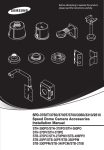
5. Installing guide bar and saw chain
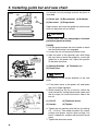
A standard saw unit package contains the items as
illustrated.
F5-1
(1) Power unit (2) Bar protector (3) Guide bar
(4) Saw chain (5) Plug wrench
Open the box and install the guide bar and the saw
chain on the power unit as follows:
WARNING
The saw chain has very sharp edges. Use thick
protective gloves for safety.
F5-2
(1)
[G3200]
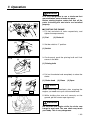
1. Pull the guard towards the front handle to check
that the chain brake is not engaged.
2. Loosen the nut and remove the chain cover.
3. Gear the chain to the sprocket and, while fitting
the saw chain around the guide bar, mount the
guide bar to the power unit. Adjust the position
of the chain tensioner.
(1) Moving direction
(3) Chain cover
(2)
(3)
(2) Tensioner nut
NOTE
Pay attention to the correct direction of the saw
chain.
F5-3
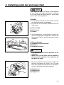
4. Fit the chain cover to the power unit and fasten
the nuts to finger tightness.
5. While holding up the tip of the bar, adjust the
chain tension by turning the tensioner screw until
the tie straps just touch the bottom side of the
bar rail.
(1) Lift UP
(3) Loosen
(2) Tensioner screw
(4) Tighten
6. Tighten the nut securely with the bar tip held up
(12 ~ 15 N·m). Then check the chain for smooth
rotation and proper tension while moving it by
hand. If necessary, readjust with the chain cover
loose.
7. Tighten the tensioner screw.
8
5. Installing guide bar and saw chain
NOTE
A new chain will expand its length in the beginning
of use. Check and readjust the tension frequently
as a loose chain can easily derail or cause rapid
wear of itseif and the guide bar.
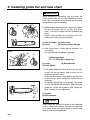
[G3200EZ]
1. Pull the guard towards the front handle to check
that the chain brake is not engageg.
2. Loosen the nut assembly and dismount the
chain cover.
F5-4
(1)
(1) Nut assembly
(2) Chain cover
(3) Loosen
(2)
(3)
3. Set the guide bar to the power unit, gear the
chain to the sprocket of clutch drum and fit it into
the groove of the bar and the sprocket at the tip
of the bar.
F5-5
(2)
(1)
(3)
(4)
(1) Moving direction
(2) Sprocket of the clutch drum
(3) Guide bar
(4) Sprocket of the bar
WARNING
• Pay attention to the correct direction of the
saw chain.
• Make sure to fit the chain into the groove of
the bar and the sprocket. If not, you may fail
to tighten the chain.
F5-6
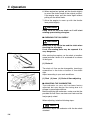
4. Move the guide bar back and forth to adjust the
position of projection A, B and C to fit in each
hole. By inserting the projections into the bottom
of holes, attach the chain cover securely.
(3)
(1)
(1) Projection A
(2) Projection B
(3) Projection C
(2)
9
5. Installing guide bar and saw chain
IMPORTANT
While temporary tightening, you may hear the
“click” sound. But do not stop tightening at that
time. This sound does not mean that the saw chain
and guide bar were assembled.
F5-7
(3)
(2)
(1)
(4)
(4)
(1) Nut assembly (2) Chain cover
(3) Lever
(4) Proper tension, No gap
6. After fixing them, attach the bar protector for
your safety.
Pull the lever up and tighten it securely.
F5-8
(3)
5. While holding the chain cover, temporary tighten
the nut assembly and fix the bar and chain
cover. (You can fix them even by tightening the
lever.)
Check if the saw chain fits on the bar rail. If not,
readjust by loosen the nut assembly.
(1)
(2)
Tightening torque:
7.9 ~ 12.8 N·m {80~130kgf-cm}
(1) Lever
(3) Fully tighten
(2) Bar protector
7. If the chain becomes loose while using the unit,
attach the bar protector and loosen the nut
assembly around 4 turns.
Dismount the protector and check if the chain fits
on the bar rail. If not, readjust by loosen the nut
assembly.
Temporary tighten the nut assembly. The chain
is to be tensioned automatically. After fixing the
guide bar, mount the protector and tighten the
lever securely for fully tightening.
F5-9
(1) Loosen
(2) Bar protector
(1)
(2)
NOTE
A new chain will expand its length in the beginning
of use. Check and readjust the tension frequently
as a loose chain can easily derail or cause rapid
wear of itself and the guide bar.
10
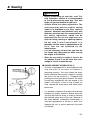
6. Fuel and Chain oil
WARNING
• Gasoline is very flammable. Avoid
smoking or bringing any flame or
sparks near fuel. Make sure to stop the
engine and allow it cool before
refueling the unit. Select outdoor bare
ground for fueling and move at least
3m (10ft) away from the fueling point
before starting the engine.
• The RedMax engines are lubricated by oil
specially formulated for air-cooled 2-cycle
gasoline engine use. If RedMax oil is not
available, use an anti-oxidant added
quality oil expressly labeled for air-cooled
2-cycle engine use. (JASO FC GRADE
OIL or ISO EGC GRADE)
• Do not use BIA or TCW (2-stroke watercooling type) mixed oil.
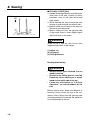
■ RECOMMENDED MIXING RATIO
GASOLINE 50:OIL 1
50:1 MIXING CHART
GASOLINE gal. 1
2
3
4
5
2-CYCLE OIL fl.oz 2.6 5.2 7.8 10.4 13
GASOLINE liter
2-CYCLE OIL ml
1
20
2
40
3
60
4
80
5
100
• Exhaust emission are controlled by the
fundamental engine parameters and
components(eq., carburation, ignition
timing and port timing) without
addition of any major hardware or the
introduction of an inert material during
combustion.
• These engines are certified to operate on
unleaded gasoline.
• Make sure to use gasoline with a
minimum octane number of 89 RON
(USA/Canada: 87AL)
• If you use a gasoline of a lower octane
value than prescribed, there is a danger
that the engine temperature may rise and
an engine problem such as piston seizing
may consequently occur.
• Unleaded gasoline is recommended to
reduce the contamination of the air for the
sake of your health and the environment.
• Poor quality gasolines or oils may damage
sealing rings, fuel lines or fuel tank of the
engine.
■ HOW TO MIX FUEL
IMPORTANT
Pay attention to agitation.
1. Measure out the quantities of gasoline
and oil to be mixed.
2. Put some of the gasoline into a clean,
approved fuel container.
3. Pour in all of the oil and agitate well.
4. Pour In the rest of gasoline and agitate
11
6. Fuel and Chain oil
again for at least one minute. As some
oils may be difficult to agitate depending
on oil ingredients, sufficient agitation is
necessary for the engine to last long. Be
careful that, if the agitation is insufficient,
there is an increased danger of early
piston seizing due to abnormally lean
mixture.
5. Put a clear indication on the outside of the
container to avoid mixing up with gasoline
or other containers.
6. Indicate the contents on outside of
container for easy identification.
■ FUELING THE UNIT
1. Untwist and remove the fuel cap. Rest the
cap on a dustless place.
2. Put fuel into the fuel tank to 80% of the full
capacity.
3. Fasten the fuel cap securely and wipe up
any fuel spillage around the unit.
WARNING
1. Select bare ground for fueling.
2. Move at least 10feet (3meters) away
from the fueling point before starting
the engine.
3. Stop the engine before refueling the
unit. At that time, be sure to sufficiently
agitate the mixed gasoline in the
container.
FOR YOUR ENGINE LIFE, AVOID;
1. FUEL WITH NO OIL(RAW GASOLINE) –
It will cause severe damage to the internal
engine parts very quickly.
2. GASOHOL – It can cause deterioration of
rubber and/or plastic parts and disruption
of engine lubrication.
3. OIL FOR 4-CYCLE ENGINE USE – It can
cause spark plug fouling, exhaust port
blocking, or piston ring sticking.
4. Mixed fuels which have been left
unused for a period of one month or
more may clog the carburetor and result
in the engine failing to operate properly.
12
5. In the case of storing the product for a
long period of time, clean the fuel tank
after rendering it empty. Next, activate the
engine and empty the carburetor of the
composite fuel.
6. In the case of scrapping the used mixed
oil container, scrap it only at an authorized
repository site.
NOTE
As lot details of quality assurance, read the
description in the section Limited Warranty
carefully. Moreover, normal wear and
change in product with no functional
influence are not covered by the warranty.
Also, be careful that, if the usage in the
instruction manual is not observed as to the
mixed gasoline, etc. described therein, it
may not be covered by the warranty.
■ CHAIN OIL
Use motor oil SAE 10W-30 all year round, or
SAE 30-40 in summer and SAE 20 in winter.
NOTE
Do not use waste or regenerated oil that can
cause damage to the oil pump.
7. Operation
WARNING
It is very dangerous to run a chainsaw that
mounts broken parts or lacks any parts.
Before starting engine, make sure that all the
parts including bar and chain are installed
properly.
F7-1
(1)
(2)
■ STARTING THE ENGINE
1. Fill fuel and chain oil tanks respectively, and
tighten the caps securely.
(1) Fuel
F7-2
(2) Chain oil
(1)
2. Set the switch to “I” position.
(1) Switch
F7-3
3. Continuously push the priming bulb until fuel
comes in the bulb.
(1)
(1) Priming bulb
F7-4
4. Pull out the choke knob completely to close the
choke.
(1)
(1) Choke knob
(2) Close
(3) Open
NOTE
(2)
F7-5
(3)
When restarting immediately after stopping the
engine, you need not to pull out the choke knob.
5. While holding the saw unit securely on the
ground, pull the starter rope vigorously.
WARNING
Do not start the engine while the chain saw
hangs in one hand. The saw chain may touch
your body. This in very dangerous.
13
7. Operation
6. When engine has ignited, pull the throttle slightly
to return the choke knob to the original position.
If the engine stops, pull the starter again without
pulling out the choke knob.
7. Allow the engine to warm up with the throttle
lever pulled slightly.
WARNING
Keep clear of the saw chain as it will start
rotatIng upon starting of engine.
■ CHECKING THE OIL SUPPLY
WARNING
Make sure to set up the bar and the chain when
checking the oil supply.
If not, the rotating parts may be exposed. It is
very dangerous.
F7-6
After starting the engine, run the chain at medium
speed and see if chain oil is scattered off as shown
in the figure.
(1) Chain oil
F7-7
The chain oil flow can be changed by inserting a
screwdriver in the hole on bottom of the clutch
side.
Adjust according to your work conditions.
(1) Rich (2) Lean (3) Chain oil flow adjusting
■ ADJUSTING THE CARBURETOR
The carburetor on your unit has been factory
adjusted, but may require fine tuning due to a
change in operating conditions.
Before adjusting the carburetor, make sure that the
provided air/fuel filters are clean and fresh and the
fuel properly mixed.
When adjusting, take the following steps:
NOTE
Be sure to adjust the carburetor with the bar chain
attached.
14
7. Operation
F7-8
(1)
1. H and L needles are restricted within the number
of turn as shown below.
(2)
(3)
H needle –1/4
L needle –1/4
2. Start engine and allow it to warm up in low
speed for a few minutes.
3. Turn idle adjusting screw (T) counter-clockwise
so that saw chain does not turn. If idling speed is
too slow, turn the screw clockwise.
4. Make a test cut adjust the H needle for best
cutting power, not for maximum speed.
(1) L needle
(2) H needle
(3) Idle adjusting screw
F7-9
(3)
(1)
(2)
■ CHAIN BRAKE
This machine is equipped with an automatic brake
to stop saw chain rotation upon occurrence of
kickback during saw cutting. The brake is
automatically operated by inertial force, which acts
on the weight fitted inside the front guard.
This brake can also be operated manually with the
front guard turned down to the guide bar.
To release the brake, pull up the front guard toward
the front handle till a “click” sound is heard.
(1) Release
(2) Activate
(3) Front guard
IMPORTANT
Be sure to confirm brake operation during daily
inspection.
F7-10
How to confirm:
1) Turn off the engine.
2) Holding the chain saw horizontally, release your
hand from the front handle, hit the tip of the
guide bar to a stump or a piece of wood, and
confirm brake operation. Operating level varies
by bar size.
In case the brake is not effective, ask our dealer for
inspection and repairs.
If the engine keeps rotating at high speed with the
brake engaged, the clutch will overheat causing
trouble.
15
7. Operation
When the brake engages during operation,
immediately release the throttle lever to stop the
engine.
■ STOPPING THE ENGINE
1. Release the throttle lever to allow the engine to
idle for a few minutes.
2. Set the switch to the “O” (STOP) position.
F7-11
(1)
(1) Switch
■ CARBURETOR ANTI-FREEZE MECHANISM
Operating chain saws in temperatures of 0 – 5°C at
times of high humidity may result in ice forming
within the carburetor, and this in turn may cause
the output power of the engine to be reduced or for
the engine to fail to operate smoothly.
This product has accordingly been designed with a
ventilation hatch on the right side of the surface of
the insulator cover to allow warm air to be supplied
to the engine and to thereby prevent icing from
occurring.
Under normal circumstances the product should be
used in the normal operating mode, i.e., in the
mode to which it is set at the time of shipment.
However when the possibility exists that icing may
occur, the unit should be set to operate in the antifreeze mode before use.
F7-12
(1)
(2)
(3)
Stop the engine, remove the cylinder cover and
install the grommet A to the appropriate position of
the mode.
See ■ Maintenance part for how to remove the
cylinder cover.
(4) (5)
16
(5)
(1) Normal operation mode
(2) Anti-freeze mode
(3) Insulator
(4) Carburetor (5) Grommet A
8. Sawing
WARNING
• Before proceeding to your job, read "For
Safe Operation" section It is recommended
to first practice sawing easy logs. This also
helps you get accustomed to your unit.
• Always follow the safety regulations. The
chain saw must only be used for cutting
wood. It is forbidden to cut other types of
material. Vibrations and kickback vary with
different materials and the requirements of
the safety regulations would not be
respected. Do not use the chain saw as a
lever for lifting, moving or splitting objects.
Do not lock it over fixed stands. It is
forbidden to hitch tools or applications to the
P.t.o. that are not specified by the
manufacturer.
• It is not necessary to force the saw into the
cut. Apply only light pressure while running
the engine at full throttle.
• When the saw chain is caught in the cut, do
not attempt to pull it out by force, but use a
wedge or a lever to open the way.
F8-1
■ GUARD AGAINST KICKBACK (F8-1)
• This saw is equipped with a chain brake that will
stop the chain in the event of kickback if
operating properly. You must check the chain
brake operation before each usage by running
the saw at full the throttle for I -2 seconds and
pushing the front hand guard forward. The chain
should stop immediately with the engine at full
speed. If the chain is slow to stop or does not
stop, replace the brake band and clutch drum
before use.
• It is extremely important that the chain brake be
checked for proper operation before each use
and that the chain be sharp in order to maintain
the kickback safety level of this saw. Removal of
the safety devices, inadequate maintenance, or
incorrect replacement of the bar or chain may
increase the risk ot serious personal injury due
to kickback.
17
8. Sawing
F8-2
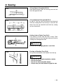
■ FELLING A TREE (F8-2)
1. Decide the felling direction considering the
wind, lean of the tree, location of heavy
branches, ease of job after felling and
other factors.
2. While clearing the area around the tree,
arrange a good foothold and retreat path.
3. Make a notch cut one-third of the way into
the tree on the felling side.
4. Make a felling cut from the opposite side
of the notch and at a level slightly higher
than the bottom of the notch.
WARNING
When you fell a tree, be sure to warn your
neighboring workers of the danger.
(1) Notch cut
(2) Felling cut
(3) Felling direction
Bucking and Limbing
WARNING
• Always ensure your foothold. Do not
stand on the log.
• Be alert to the rolling over of a cut log.
Especially when working on a slope,
stand on the uphill side of the log.
• Follow the instructions in "For Safe
Operation" to avoid kickback of the
saw.
Before starting work, check the direction of
bending force inside the log to be cut.
Always finish cutting from the opposite side
of bending direction to prevent the guide bar
from being caught in the cut.
18
8. Sawing
F8-3
F8-4
F8-5
A Log lying on the ground (F8-3)
Saw down halfway, then roll the log over and cut
from the opposite side.
A Log hanging off the ground (F8-4)
In area A, saw up from the bottom one-third and
finish by sawing down from the top. In area B, saw
down from the top one-third and finish by sawing
up from the bottom.
Cutting Limb of Fallen Tree (F8-5)
First check to which side the limb is bent. Then
make the initial cut from the bent side and finish by
sawing from the opposite side.
WARNING
Be alert to the springing back of a cut limb.
F8-6
Pruning of Standing Tree (F8-6)
Cut up from the bottom, finish down from the top.
WARNING
•
•
•
•
Do not use an unstable foothold or ladder.
Do not overreach.
Do not cut above shoulder height.
Always use your both hands to grip the saw.
19
9. Maintenance
Maintenance, replacement, or repair of the
emission control device and systems may be
performed by any non-road engine repair
establishment or individual.
WARNING
Before cleaning, the inspecting or repairing the
unit, make sure that engine has stopped and is
cool. Disconnect the spark plug to prevent
accidental starting.
F9-1
(1)
■ MAINTENANCE AFTER EACH USE
1. Oiling port
Dismount the guide bar and check the oiling port
for clogging.
(1) Oiling port
2. Guide bar
When the guide bar is dismounted, remove
sawdust in the bar groove and the oiling port.
Grease the nose sprocket from the feeding port on
the tip of the bar.
F9-2
(1) Oiling port (2) Grease port (3) Sprocket
3. Others
Check for fuel leakage and loose fastenings and
damage to major parts, especially handle joints
and guide bar mounting. If any defects are found,
make sure to have them repaired before operating
the saw again.
A
F9-3
■ PERIODICAL SERVICE POINTS
(Every 25 hours use)
(1)
(2)
B
(2)
(1)
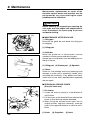
1. Air cleaner
1. Loosen the knob by moving it to the direction A
until it clicks.
2. Pull the cover to the direction B and unfasten the
hooks so that the cover can be detached.
3. When fixing the cylinder cover back into its
original position, align the 3 hooks(3), move the
cover in the opposite direction of removal until it
clicks.
(3)
(1) Knob
20
(2) Projection
(3) Hook
9. Maintenance
F9-4
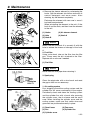
4. Remove the cleaner element by unfastening the
hooks. Split the element into halves and wash in
neutral detergent and warm water. After
cleaning, dry the element completely.
Exchange the element with new one in case it
has been contaminated.
When reinstalling the element to the unit, fit the
hook A and the hole, and then inset the element
to the unit.
(1)
(2)
(3)
(4)
(2)
(5)
F9-5
(1) Hooks
(3) Hole
(5) Hook B
(2) Air cleaner element
(4) Hook A
NOTE
Make sure that the hook A is correctly fit with the
hole to reduce the chance of damage of the hook
A.
2. Fuel filter
Using a wire hook, take out the filter from the filler
port. Clean away the dirt attached to the filter.
Replace with a new one if needed.
(1)
(1) Fuel filter
NOTE
F9-6
Never bend the filter pipe when returning it.
3. Spark plug
Champion
RCJ-7Y
F9-7
Clean the electrodes with a wire brush and reset
the gap to 0.65 mm as necessary.
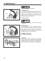
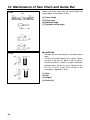
1. Air cooling system
Dust clogging around the cooling system and the
cylinder fins will cause overheating of the engine.
Periodically check and clean the cooling system
and the cylinder fins with a brush after removing
the cylinder cover, the air cleaner and the recoil
case. When installing the cylinder cover and the
cooling system, make sure that switch wires and
grommets are positioned correctly in place.
(1) Recoil case
(3) Fan
(5) Cylinder cover
(2) Fan cover
(4) Cylinder fins
21
9. Maintenance
NOTE
Be sure to block the air intake hole.
F9-8
2. Spark arrester
The muffler is equipped with a spark arrester to
prevent red hot carbon from flying out of the
exhaust outlet. Periodically check and clean as
necessary with a wire brush after removing two
muffler cover nuts and one screw.
(1) Spark arrester
NOTE
Never use a muffler if the spark arrester is missing
or defective.
3. Exhaust port
Remove the muffler, insert a screwdriver into the
vent, and wipe away any carbon buildup after
every 100 hours of use. Wipe away any carbon
buildup on the muffler exhaust vent and the
cylinder exhaust port at the same time.
F9-9
(1) Muffler exhaust vent
(2) Cylinder exhaust port
5. Sprocket
Check for cracks and for excessive wear interfering
with the chain drive. If the wear is considerable,
replace it with new one. Never fit a new chain on a
worn sprocket, or a worn chain on a new sprocket.
F9-10
0.5mm
22
10. Maintenance of Saw Chain and Guide Bar
■ SAW CHAIN
F10-1
WARNING
It is very important for smooth and safe
operation to keep the cutters always sharp.
Your cutters need to be sharpened when:
• Sawdust becomes powder-like.
• You need extra force to saw in.
• The cut way does not go straight.
• Vibration increases.
• Fuel consumption increases.
Cutter setting standards:
WARNING
Be sure to wear safety gloves.
Before filing:
• Make sure the saw chain is held securely.
• Make sure the engine is stopped.
• Use a round file of proper size for your chain.
Chain type:
File size:
25AP, 91VG
5/32 in (4.0mm)
Place your file on the cutter and push straight
forward. Keep the file position as illustrated.
(F10-1)
F10-2
After every cutter has been set, check the depth
gauge and file it to the proper level as illustrated.
(F10-2)
WARNING
Be sure to round off the front edge to reduce
the chance of kickback or tie-strap breakage.
(1) Appropriate gauge checker
(2) Make the shoulder round
(3) Depth gauge standard
23
10. Maintenance of Saw Chain and Guide Bar
F10-3
Make sure every cutter has the same length and
edge angles as illustrated. (F10-3)
(4)
(5)
(6)
(7)
F10-4
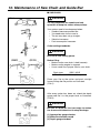
■ GUIDE BAR
• Reverse the bar occasionally to prevent partial
wear.
• The bar rail should always be a square. Check
for wear of the bar rail. Apply a ruler to the bar
and the outside of a cutter. If a gap is observed
between them, the rail is normal. Otherwise, the
bar rail is worn. Such a bar needs to be
corrected or replaced. (F10-4)
(1)
(2)
(3)
(4)
24
Cutter length
Filing angle
Side plate angle
Top plate cutting angle
Ruler
Gap
No gap
Chain tilts
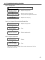
11. Troubleshooting Guide
Case 1. Starting failure:
Make sure the icing prevention system is not working.
Check fuel for water or
substandard mixture.
Replace with proper fuel.
➜
Remove and dry the spark plug.
Then pull the starter again with no choke.
➜
Replace with a new plug.
➜
➜
Check for engine flooding.
➜
Check the spark.
Case 2. Lack of power/Poor acceleration/Rough idling
Check fuel for water or
substandard mixture.
Replace with proper fuel.
➜
Clean.
➜
Readjust speed needles.
➜
Replace.
➜
Clean.
➜
➜
Check air filter and fuel
filter for clogging.
➜
Check carburetor for
inadequate adjustment.
Case 3. Oil does not come out
Check oil for
substandard quality.
➜
Check oil passage
and ports for clogging.
When your unit seems to need further service, please consult with our
service shop in your area.
25
12. Storage
1. Empty the fuel tank and run the engine out of
fuel.
2. Empty the oil tank.
3. Clean the entire unit.
4. Store the unit in a dry place out of the reach of
children.
26
13. Parts list
CHAINSAWS
G3200
G3200EZ
NOTE :
1. Use KOMATSU ZENOAH genuine parts as specified in the parts list for repair and/or
replacement.
2. KOMATSU ZENOAH does not warrant the machines, which have been damaged by the
use of any parts other than those specified by the company.
3. When placing parts orders for repair and/or replacement, check if the model name and the
serial number are applicable to those specified in the parts list, then use parts number
described in the parts list.
4. The contents described in the parts list may change due to improvement.
5. The parts for the machine shall be supplied seven (7) years after the machine is
discontinued. [It is possible that some specific parts may be subject to change of their
delivery term and list price within the limit of seven (7) years after the machine is
discontinued. It is also possible that some parts may be available even after the limit of
seven (7) years.]
APPLICABLE SERIAL NUMBERS :
G3200 : 404766 and up
Oct. 2004
G3200EZ : 400001 and up
27
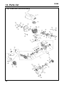
13. Parts list
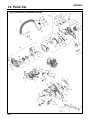
Fig.1 POWER UNIT (S/N 404766 and up)
28
G3200
G3200
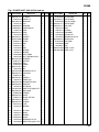
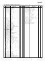
Fig.1 POWER UNIT (S/N 404766 and up)
Key# PART NUMBER
DESCRIPTION
Q'TY NOTE
/UNIT
1
2
3
4
5
6
7
8
9
10
11
12
13
14
15
16
17
18
19
24
25
26
27
28
29
30
31
32
33
34
35
36
37
38
39
40
41
42
43
44
45
46
848-C30-12A1
T2200-14210
848-C30-2101
2629-21130
06030-06201
04065-03212
2169-21210
848-8AC-3210
2616-21230
848-C30-21D1
848-8Y5-6000
T2200-41110
T2102-41210
T2200-41310
3310-41320
3310-41410
1650-41510
T2200-42000
4820-13180
848-C3A-15B0
T2200-15110
T2200-15310
T2100-15210
848-C3A-15M1
2850-15230
848-815-1400
848-C30-14A1
T2200-31120
848-C30-14B1
3330-14121
848-C3A-8100
848-C30-82A2
2867-82210
848-825-1601
848-C30-82F2
T2200-83100
848-C30-31A2
T2200-51110
848-C30-5121
848-C30-51E2
T2041-51210
3310-51310
CYLINDER
GASKET, cyl
CASE ASSY
• PIN
• BEARING
• SNAPRING ø32
• SEAL
• SEAL
• STUD
• GASKET
SPACER
PISTON
RING
PIN
RING
BEARING
WASHER
SHAFT COMP.
BOLT TORX M5xL20 T27
ARRESTER
MUFFLER
STAY
GASKET
BOLT
NUT
SCREW M5xL14 T27
INSULATOR
CAP
GASKET, in
GASKET,carb
CARBURETOR ASSY
MANIFOLD
BOLT M4x70
SCREW TP5(P-tight)xL16 T27
ROD CHOKE
CLEANER
COVER
DRUM 1/4x8T ø60
CLUTCH
• SPRING
PLATE
BEARING
1
1
1
3
2
1
1
1
1
1
1
1
1
1
2
1
2
1
8
1
1
1
1
2
2
1
1
1
1
1
1
1
2
1
1
1
1
1
1
3
1
1
50
51
52
53
54
55
2841-55112
2850-55121
2850-55211
T2200-55610
2670-55410
2670-54630
OIL PUMP
WORM
WASHER
COVER
SCREW M4xL14 T20
SCREW TP4(B-tight)xL12 T20
1
1
1
1
2
1
Key# PART NUMBER
DESCRIPTION
56 T2100-23200 FILTER COMP.
57 848-C30-6731 PIPE IN COMP.
58 T2200-21400 PIPE OUT COMP.
59 848-C35-7111 ROTOR COMP.
60 848-C35-7121 COIL ASSY
61
2850-72110 • CAP
62
1400-72121 • SPRING
63
5500-72130 • GROMMET
64
1650-43230 NUT M8xP1.0
65
2670-55410 SCREW M4xL14 T20
66 3699-90032-10 SPARK PLUG
67 T2100-31500 PIPE COMP.
68
2850-81900 PUMP
69
2850-82611 PIPE
70 848-C3A-90F0 LABEL, caution
71 848-C30-90E0 LABEL, choke
Q'TY NOTE
/UNIT
1
1
1
1
1
1
1
1
1
2
1
1
1
1
1
1
29
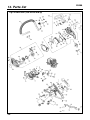
13. Parts list
Fig.2 POWER UNIT (S/N 404766 and up)
30
G3200
G3200
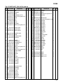
Fig.2 POWER UNIT (S/N 404766 and up)
Key# PART NUMBER
1
2
3
4
5
6
7
8
9
10
11
848-C30-82H3
848-C30-82G2
848-C30-25A2
848-815-1400
848-825-1911
848-C30-25C2
848-C30-25D0
T2200-21230
848-C30-6612
848-C30-66F1
848-825-1911
DESCRIPTION
ROD
GROMMET
CASE
SCREW M5xL14 T27
SCREW TP5(P-tight)xL19 T27
KNOB
CLIP
BOLT
PLATE
CATCHER
SCREW TP5(P-tight)xL19 T27
Q'TY NOTE
/UNIT
1
1
1
4
1
1
1
1
1
1
1
14
2850-74102 SWITCH ASSY
15 848-C30-72C1 CORD EARTH
16 848-C30-72B1 CORD SWITCH
1
1
1
20 848-C35-7502 STARTER ASSY
21 848-C35-75C1 • REEL
22
2841-75300 • SPRING COMP.
23 T2044-75410 • ROPE ø3
1
1
1
1
25
26
27
28
29
30
31
32
33
34
35
36
37
38
39
40
41
42
1400-75170
T2044-75420
T1812-75150
848-C30-74B0
848-C30-74A1
848-825-1911
T2200-32100
848-825-1901
848-C30-3311
848-C30-33C1
3356-33321
848-C30-33E3
848-C30-33L1
848-825-1911
2841-31801
2841-31820
2877-31800
2841-31820
• KNOB
• KNOB CAP
• SCREW M5xL12
• CUSHION
COVER
SCREW TP5(P-tight)xL19 T27
HANDLE
SCREW TP5(P-tight)xL19 T27
HANDLE COMP.
LEVER
SPRING
ARM
COVER
SCREW TP5(P-tight)xL19 T27
CAP ASSY
• GASKET
CAP ASSY
• GASKET
1
1
1
1
1
3
1
4
1
1
1
1
1
1
1
1
1
1
48
49
50
51
52
53
54
55
56
2850-34501
848-C30-85U0
848-C30-8530
1850-85300
2850-34350
848-C30-37A1
848-C30-37B1
848-C30-37C1
848-825-1901
BREATHER ASSY
GROMMET
PIPE ASSY
FILTER
COLLAR
SPRING F
SPRING M
SPRING P
SCREW TP5(P-tight)xL19 T27
1
1
1
1
1
1
1
1
5
Key# PART NUMBER
DESCRIPTION
Q'TY NOTE
/UNIT
57 848-C30-37D2 HELPER
58 848-C30-37E1 BAND
59 848-825-1601 SCREW TP5(P-tight)xL16 T27
60 01640-20508 WASHER
2
1
1
1
65
66
67
68
69
70
71
72
73
74
75
76
77
78
79
80
81
82
83
84
85
86
87
88
1
4
1
1
1
1
1
1
1
1
1
1
1
1
1
1
1
1
1
1
1
1
1
1
848-C3A-5400
2670-54630
848-C30-54A2
2850-54120
2850-54130
2850-54140
2850-54211
848-C60-5423
2872-54230
2851-54270
3330-75411
3310-53331
2851-54301
2851-54350
2670-54411
T2200-54510
3356-24140
2670-54610
848-C30-53C2
848-C30-66C1
2841-53240
848-C33-66K0
2671-53230
3350-53410
BRAKE ASSY
• SCREW TP4(B-tight)xL12 T20
• GUARD
• SPRING
• SCREW
• SPACER
• SPACER
• WEIGHT
• SPRING
• SPRING
• WASHER
• NUT
• LEVER COMP.
• ROLLER
• ARM
• BAND
• ROLLER
• SPRING
• COVER
• PLATE(B)
• SCREW
• NUT
• GEAR
NUT
91 848-C30-90K0 LABEL
92 848-C30-90L0 LABEL
93 848-C3A-90B0 LABEL, cover
94 848-C3A-90C1 LABEL, recoil
1
1
1
1
31
13. Parts list
Fig.3 POWER UNIT (S/N 400001 and up)
32
G3200EZ
G3200EZ
Fig.3 POWER UNIT (S/N 400001 and up)
Key# PART NUMBER
DESCRIPTION
Q'TY NOTE
/UNIT
1
2
3
4
5
6
7
8
9
10
11
12
13
14
15
16
17
18
19
24
25
26
27
28
29
30
31
32
33
34
35
36
37
38
39
40
41
42
43
44
45
46
848-C30-12A1
T2200-14210
848-C30-2101
2629-21130
06030-06201
04065-03212
2169-21210
848-8AC-3210
2616-21230
848-C30-21D1
848-8Y5-6000
T2200-41110
T2102-41210
T2200-41310
3310-41320
3310-41410
1650-41510
T2200-42000
4820-13180
848-C3A-15B0
T2200-15110
T2200-15310
T2100-15210
848-C3A-15M1
2850-15230
848-815-1400
848-C30-14A1
T2200-31120
848-C30-14B1
3330-14121
848-C3A-8100
848-C30-82A2
2867-82210
848-825-1601
848-C30-82F2
T2200-83100
848-C30-31A2
T2220-51110
848-C30-5121
848-C30-51E2
T2041-51210
3310-51310
CYLINDER
GASKET, cyl
CASE ASSY
• PIN
• BEARING
• SNAPRING ø32
• SEAL
• SEAL
• STUD
• GASKET
SPACER
PISTON
RING
PIN
RING
BEARING
WASHER
SHAFT COMP.
BOLT TORX M5xL20 T27
ARRESTER
MUFFLER
STAY
GASKET
BOLT
NUT
SCREW M5xL14 T27
INSULATOR
CAP
GASKET, in
GASKET,carb
CARBURETOR ASSY
MANIFOLD
BOLT M4x70
SCREW TP5(P-tight)xL16 T27
ROD CHOKE
CLEANER
COVER
DRUM 3/8x6T ø60
CLUTCH
• SPRING
PLATE
BEARING
1
1
1
3
2
1
1
1
1
1
1
1
1
1
2
1
2
1
8
1
1
1
1
2
2
1
1
1
1
1
1
1
2
1
1
1
1
1
1
3
1
1
50
51
52
53
54
55
2841-55112
2850-55121
2850-55211
T2200-55610
2670-55410
2670-54630
OIL PUMP
WORM
WASHER
COVER
SCREW M4xL14 T20
SCREW TP4(B-tight)xL12 T20
1
1
1
1
2
1
Key# PART NUMBER
DESCRIPTION
56 T2100-23200 FILTER COMP.
57 848-C30-6731 PIPE IN COMP.
58 T2200-21400 PIPE OUT COMP.
59 848-C35-7111 ROTOR COMP.
60 848-C35-7121 COIL ASSY
61
2850-72110 • CAP
62
1400-72121 • SPRING
63
5500-72130 • GROMMET
64
1650-43230 NUT M8xP1.0
65
2670-55410 SCREW M4xL14 T20
66 3699-90032-10 SPARK PLUG
67 T2100-31500 PIPE COMP.
68
2850-81900 PUMP
69
2850-82611 PIPE
70 848-C3D-99F0 LABEL, caution
71 848-C30-90E0 LABEL, choke
Q'TY NOTE
/UNIT
1
1
1
1
1
1
1
1
1
2
1
1
1
1
1
1
33
13. Parts list
Fig.4 POWER UNIT (S/N 400001 and up)
34
G3200EZ
G3200EZ
Fig.4 POWER UNIT (S/N 400001 and up)
Key# PART NUMBER
1
2
3
4
5
6
7
8
9
10
11
848-C30-82H3
848-C30-82G2
848-C30-25A2
848-815-1400
848-825-1911
848-C30-25C2
848-C30-25D0
T2200-21230
848-C30-6612
848-C30-66F1
848-825-1911
DESCRIPTION
ROD
GROMMET
CASE
SCREW M5xL14 T27
SCREW TP5(P-tight)xL19 T27
KNOB
CLIP
BOLT
PLATE
CATCHER
SCREW TP5(P-tight)xL19 T27
Q'TY NOTE
/UNIT
1
1
1
4
1
1
1
1
1
1
1
14
2850-74102 SWITCH ASSY
15 848-C30-72C1 CORD EARTH
16 848-C30-72B1 CORD SWITCH
1
1
1
20
21
22
23
24
25
26
27
28
29
30
31
32
33
34
35
36
37
38
39
40
41
42
848-C30-7502
848-C30-7520
2841-75300
T2044-75410
T2044-75520
1400-75170
T2044-75420
T1812-75150
848-C30-74B0
848-C30-74A1
848-825-1911
T2200-32100
848-825-1901
848-C30-3311
848-C30-33C1
3356-33321
848-C30-33E3
848-C30-33L1
848-825-1911
2841-31801
2841-31820
2877-31800
2841-31820
STARTER ASSY
• REEL COMP.
• SPRING COMP.
• ROPE ø3
• PULLEY
• KNOB
• KNOB CAP
• SCREW M5xL12
• CUSHION
COVER
SCREW TP5(P-tight)xL19 T27
HANDLE
SCREW TP5(P-tight)xL19 T27
HANDLE COMP.
LEVER
SPRING
ARM
COVER
SCREW TP5(P-tight)xL19 T27
CAP ASSY
• GASKET
CAP ASSY
• GASKET
1
1
1
1
1
1
1
1
1
1
3
1
4
1
1
1
1
1
1
1
1
1
1
48
49
50
51
52
53
54
55
56
2850-34501
848-C30-85U0
848-C30-8530
1850-85300
2850-34350
848-C30-37A1
848-C30-37B1
848-C30-37C1
848-825-1901
BREATHER ASSY
GROMMET
PIPE ASSY
FILTER
COLLAR
SPRING F
SPRING M
SPRING P
SCREW TP5(P-tight)xL19 T27
1
1
1
1
1
1
1
1
5
Key# PART NUMBER
DESCRIPTION
Q'TY NOTE
/UNIT
57 848-C30-37D2 HELPER
58 848-C30-37E1 BAND
59 848-825-1601 SCREW TP5(P-tight)xL16 T27
60 01640-20508 WASHER
2
1
1
1
65 848-C36-5401 BRAKE ASSY
66
2670-54630 • SCREW TP4(B-tight)xL12 T20
67 848-C30-54A2 • GUARD
68
2850-54120 • SPRING
69
2850-54130 • SCREW
70
2850-54140 • SPACER
71
2850-54211 • SPACER
72 848-C60-5423 • WEIGHT
73
2872-54230 • SPRING
74
2851-54270 • SPRING
75
3330-75411 • WASHER
76
3310-53331 • NUT
77
2851-54301 • LEVER COMP.
78
2851-54350 • ROLLER
79
2670-54411 • ARM
80 T2200-54510 • BAND
81
3356-24140 • ROLLER
82
2670-54610 • SPRING
83 848-C30-53C2 • COVER
84 T2200-53200 • LINK A
85 T2200-53280 • SPRING
86 848-C30-66C1 • PLATE(B)
87 848-C30-5341 • NUT ASSY
1
3
1
1
1
1
1
1
1
1
1
1
1
1
1
1
1
1
1
1
1
1
1
91 848-C30-90K0 LABEL
92 848-C30-90L0 LABEL
93 848-C3D-90B0 LABEL, cover
94 848-C3A-90C0 LABEL, recoil
1
1
1
1
35
G3200/G3200EZ
13. Parts list
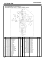
Fig.5 CARBBURETOR COMPONENTS
S/N (G3200 : 404766 and up G3200EZ : 400001 and up)
Key#
PART NUMBER
DESCRIPTION
1
2
3
4
5
6
7
8
9
10
11
12
13
14
15
16
17
18
848-C3A-8100
848-C3A-0630
3306-81380
3356-81310
2841-81270
3310-81250
3310-81240
3310-81230
T2100-06020
3304-81140
1172-81150
2850-81290
3310-81260
2850-81120
3310-81130
3310-81280
1480-81420
1148-81390
CARBURETOR ASSY
• REBUILD-KIT
• • SCREEN
• • VALVE
• • SPRING
• • PIN
• • SCREW
• • LEVER
• • GASKET KIT
• • • GASKET
• • • DIAPHRAGM
• • • GASKET
• • • DIAPHRAGM
• COVER
• SCREW
• COVER
• PLUG
• RING
36
Q'TY NOTE
/UNIT
1
1
1
1
1
1
1
1
1
1
1
1
1
1
1
1
1
1
(OP)
(OP)
Key#
PART NUMBER
19
20
21
22
23
24
25
26
27
28
29
30
31
32
33
3310-81341
2880-81470
2670-81410
848-C3A-81T0
2630-81330
3350-81380
2670-81440
2850-81190
2841-81450
T2002-81350
848-C30-81E0
2850-81430
3310-81351
2810-81530
848-C71-80N0
DESCRIPTION
• VALVE
• SCREW
• SPRING
• SHAFT
• SCREW
• SPRING
• LEVER
• SCREW
• VALVE
• SPRING
• SHAFT
• BUSHING
• SCREW
• SPRING
• PISTON
Q'TY NOTE
/UNIT
1
3
1
1
1
1
1
1
1
1
1
1
4
1
1
G3200/G3200EZ
13. Parts list
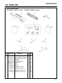
Fig.6 ACCESSORIES
S/N (G3200 : 404766 and up
Key#
PART NUMBER
1 848-CB1-2020
2 3310-52210-50
3
3617-97110
4
3320-91140
5 848-C3A-93A0
6 848-C30-0610
7
T3195-91110
8
2670-91150
9
2670-96220
10
3330-97310
11
2850-96410
12
2670-96510
G3200EZ : 400001 and up)
DESCRIPTION
BAR CV30 1/4
CHAIN OREGON 25AP-J68E
PROTECTOR 300~350mm
WRENCH
OWNER'S MANUAL
GASKET KIT
BAG
DRIVER
STOPPER (for piston)
GAUGE (for air gap)
WRENCH (T20xT25xT27)
GUIDE (for brake spring)
Q'TY NOTE
/UNIT
1
1
1
1
1
1
1
1
1
1
1
1
(OP)
(OP)
(OP)
(OP)
(OP)
(OP)
37
RedMax
CHAIN SAWS LIMITED WARRANTY
EMISSION-RELATED PARTS, FOR TWO (2) YEARS FROM THE DATE OF ORIGINAL DELIVERY, KOMATSU ZENOAH
AMERICA INC. (THE COMPANY), THROUGH ANY RedMax DEALER, WILL REPAIR OR REPLACE, FREE OF CHARGE,
FOR THE ORIGINAL AND EACH SUBSEQUENT PURCHASER, ANY PART OR PARTS FOUND TO BE DEFECTIVE IN
MATERIAL AND/OR WORKMANSHIP. EMISSION-RELATED PARTS ARE:
THE CARBURETOR ASSY, COIL ASSY, ROTOR, SPARKPLUG,
AIR FILTER, FUEL FILTER, INTAKE MANIFOLD, AND THE GASKETS
ALL OTHER PARTS EXCEPT ABOVE PARTS, FOR TWO (2) YEARS OF HOME USE, 1 YEAR COMMERCIAL USE AND
NINETY (90) DAYS FOR RENTAL USE FROM THE DATE OF ORIGINAL PURCHASE, THE COMPANY, THROUGH ANY
RedMax DEALER, WILL REPAIR OR REPLACE, FREE OF CHARGE, FOR THE ORIGINAL PURCHASER, ANY PART OF
PARTS FOUND TO BE DEFECTIVE IN MATERIAL AND/OR WORKMANSHIP. THIS IS THE EXCLUSIVE REMEDY.
THE PURCHASER SHALL BEAR COSTS OF TRANSPORTING THE UNIT TO AND FROM THE RedMax DEALER.
THE PURCHASER SHALL NOT BE CHARGED FOR DIAGNOSTIC LABOR WHICH LEADS TO THE DETERMINATION
THAT A WARRANTED PART IS DEFECTIVE, IF THE DIAGNOSTIC WORK IS PERFORMED AT THE RedMax DEALER.
THE PURCHASER OR OWNER IS RESPONSIBLE FOR THE PERFORMANCE OF THE REQUIRED MAINTENANCE AS
DEFINED BY THE MANUFACTURER IN THE OWNER/OPERATOR MANUAL.
ANY WARRANTED PART WHICH IS NOT SCHEDULED FOR REPLACEMENT AS REQUIRED MAINTENANCE, OR
WHICH IS SCHEDULED ONLY FOR REGULAR INSPECTION TO THE EFFECT OF "REPAIR OR REPLACE AS
NECESSARY" SHALL BE WARRANTED FOR THE WARRANTY PERIOD.ANY WARRANTED PART WHICH IS
SCHEDULED FOR REPLACEMENT AS REQUIRED MAINTENANCE SHALL BE WARRANTED FOR THE PERIOD OF
TIME UP TO THE FIRST SCHEDULED REPLACEMNET POINT FOR THE PART.
ANY REPLACEMENT PART THAT IS EQUIVALENT IN PERFORMANCE AND DULABILITY MAY BE USED IN NONWARRANTY MAINTENANCE OR REPAIRS, AND SHALL NOT REDUCE THE WARRANTY OBLIGATION OF THE
COMPANY.
THE COMPANY IS LIABLE FOR DAMAGES TO OTHER ENGINE COMPONENTS CAUSED BY THE FAILURE OF A
WARRANTED PARTS STILL UNDER WARRANTY.
THE WARRANTY DOES NOT APPLY TO THOSE UNITS WHICH HAVE BEEN DAMAGED BY NEGLIGENCE OF
INSTRUCTION LISTED IN THE OWNER/OPERATOR MANUAL FOR PROPER USE AND MAINTENANCE OF THE UNITS,
ACCIDENTAL MISHANDLING, ALTERATION, ABUSE, IMPROPER LUBULICATION, USE OF ANY PARTS OR ACCESSARIES
OTHER THAN THOSE SPECIFIED BY THE COMPANY, OR OTHER CAUSES BEYOND THE CONPANY'S CONTROL.
THIS WARRANTY DOES NOT COVER THOSE PARTS REPLACED BY NORMAL WEAR OR HARMLESS CHANGES IN
THEIR APPEARANCE.
THERE ARE NO OTHER EXPRESS WARRANTIES.
IMPLIED WARRANTIES INCLUDING THOSE OF MERCHANTABILITY AND FITNESS FOR A PARTICULAR PURPOSE
ARE LIMITED TO TWO (2) YEARS FOR HOME USE, ONE (1) YEAR FOR COMMERCIAL USE AND NINETY (90) DAYS
FOR RENTAL USE, FROM THE ORIGINAL DELIVERY DATE.
LIABILITIES FOR INCIDENTAL OR CONSEQUENTIAL DAMAGE UNDER ANY AND ALL WARRANTIES
ARE EXCLUDED.
SOME STATES DO NOT ALLOW LIMITATION ON HOW LONG AN IMPLIED WARRANTY LASTS OR EXCLUSION OR
LIMITATION OF INCIDENTAL OR CONSEQUENTIAL DAMAGES, SO THE ABOVE LIMINATION OR EXCLUSION MAY
NOT APPLY TO YOU.
THIS WARRANTY GIVES YOU SPECIFIC LEGAL RIGHTS, AND YOU MAY ALSO HAVE OTHER RIGHTS WHICH VARY
FROM STATE TO STATE.
IF YOU NEED TO OBTAIN INFORMATION ABOUT THE NEAREST SERVICE CENTER, PLEASE CALL KOMATSU
ZENOAH AMERICA INC. AT (770)-381-5147.
IMPORTANT: YOU WILL RECEIVE A WARRANTY REGISTRATION CARD AT TIME OF PURCHASE.PLEASE FILL
OUT THE CARD AND SEND IT TO RedMax / KOMATSU ZENOA AMERICA WITHIN SEVEN (7) DAYS.BE SURE TO KEEP
A COPY FOR YOUR RECORDS.
KOMATSU ZENOAH AMERICA INC.
4344 Shackleford Road Suite 500
Norcross, Georgia 30093
RedMax
Garantie limitée des tronçonneuses
Pièces en rapport avec les émissions de gaz d'échappement : KOMATSU ZENOAH AMERICA INC., par
l'intermédiaire de n'importe quel revendeur RedMax, réparera gratuitement ou remplacera gratuitement pour
l'acheteur initial et chaque acheteur successif toute(s) pièce(s) se révélant de constitution et/ou de montage
défectueux pendant deux (2) ans à compter de la date initiale de livraison d’une unité. Les pièces en rapport avec les
émissions de gaz d'échappement sont:
l'assemblage carburateur, l'assemblage bobine, le rotor, la bougie,
le filtre à air, le filtre à carburant, la tubulure d'admission et les joints
Toutes les pièces autres que celles mentionnées ci-dessus, deux (2) ans d’utilisation domestique, 1 an
d’utilisation commerciale et quatre-vingt-dix (90) jours pour la location à compter de la date d’achat initial. La société,
par l’intermédiaire d’un distributeur RedMax, réparera ou remplacera toute(s) pièce(s), sans frais et au bénéfice de
l’acheteur original, en prenant en charge les frais de pièces et/ou de main d’œuvre. Telles sont les limites de la
garantie.
Le coût du transport de l'unité jusqu'au revendeur RedMax et depuis celui-ci sera à la charge de l'acheteur.
L'acheteur ne supportera pas le coût de main d'oeuvre du diagnostic qui amène à la conclusion qu'une pièce
garantie est défectueuse, si ce diagnostic est effectué chez le revendeur RedMax.
L’acheteur ou propriétaire a pour responsabilité d’effectuer l’entretien obligatoire tel que défini par le fabricant dans le
manuel du propriétaire/de l'utilisateur.
Toute pièce garantie dont le remplacement n'est pas prévu dans le cadre de l’entretien obligatoire, ou pour laquelle
est seulement prévue une inspection périodique pour "remplacement ou réparation si nécessaire" sera garantie pour
la période de garantie. Toute pièce garantie arrivée à l’échéance de son premier remplacement prévu sera garantie
jusqu’à celui-ci.
Toute pièce de rechange équivalente en performance ou en durabilité peut être utilisée pour l’entretien hors-garantie
ou les réparations hors-garantie, et ce sans réduire l’obligation de garantie incombant à la société.
La société sera tenue responsable des dommages aux autres composants du moteur causés par la défaillance de
pièce(s) garantie(s) en période de garantie.
La garantie ne s'applique pas aux unités endommagées par suite de: négligence dans la mise en oeuvre des
instructions spécifiées dans le manuel du propriétaire/de l'utilisateur en vue d’une utilisation et d’un entretien correct,
fausse manœuvre accidentelle, modification, utilisation abusive, lubrification incorrecte, utilisation de pièces ou
d’accessoires autres que ceux spécifiés par la société, ou autres causes hors du contrôle de la société.
Cette garantie ne couvre pas les pièces remplacées en raison de leur usure normale ou de changements
d’apparence sans effets.
Il n'existe aucune autre garantie explicite.
Les garanties implicites, y compris la valeur marchande et la valeur d’usage pour une utilisation particulière, sont
limitées à deux (2) ans d’utilisation domestique, un (1) an d’utilisation commerciale et quatre-vingt-dix (90) jours pour
la location, à compter de la date originale de livraison.
Les responsabilités pour les dommage conséquents ou incidents sont exclues de toutes les garanties.
Certaines provinces n'autorisant pas les limitations à la durée des garanties implicites, ou les exclusions ou
limitations relatives aux dommages incidents ou conséquents, la limitation indiquée ci-dessus peut ne pas vous être
applicable.
Cette garantie vous donne des droits juridiques spécifiques, et vous pouvez également jouir d’autres droits variant
d'une province à l'autre.
Si vous désirez obtenir des informations sur le centre de service le plus proche, veuillez appeler KOMATSU
ZENOAH AMERICA INC. au (770)-381-5147
Note importante: vous recevrez une carte d'enregistrement de garantie au moment de l'achat. Veuillez la remplir et
l'adresser à RedMax / KOMATSU ZENOAH AMERICA sous sept (7) jours en prenant soin de conserver une copie
pour vous.
KOMATSU ZENOAH AMERICA INC.
4344 Shackleford Road Suite 500
Norcross, Georgia 30093
KOMATSU ZENOAH AMERICA INC.
4344 Shackleford Road Suite 500
Norcross, Georgia 30093