1
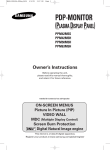
Service Manual
RCA Model 18V100
Home TV Programmer
>~
itc/i
l,
w
Studio II
<,
Home TV Programmer, Model 18V100
Operation
^
•
Testing
•
Disassembly
Parts List
RCA
Parts Distributors. Called "Tester I", the cartridge plugs
into the slot in the console and checks out the digital circuitry
PRODUCT SAFETY NOTICE
Studio
II
uses an isolated
power supply to operate the
The leakage current to ground of this
should be checked at time of game repair. See Page
electronic circuitry.
in
about 30 seconds. See Page 4 for description and Page 15
for ordering information.
s>
power unit
9 for test procedure.
SERVICE PARTS LIST AVAILABLE
TESTER CARTRIDGE AVAILABLE
For those organizations planning to service Studio
kit of Studio II repair parts is available from
games, a
Parts Distributors. This kit includes
As an
Studio
systems of
nominal cost through
aid to servicing the digital electronics
II,
a test cartridge
is
available at
to service Studio
II
all
II
video
RCA
of the parts necessary
units in the field. See Page 15 for
description and for ordering information.
sj
Table of Contents
Page
STUDIO
II
PC
BOARD EXCHANGE QUESTIONNAIRE
15
3
DESCRIPTION
3
Control Console
3
Selector Switch Unit
3
Power Supply Unit
STUDIO
II
SERVICING
4
System Checking
4
System Connections
4
Test Procedures
PC
-
4
Control Dissassembly
11
Component Replacement Procedure
11
Clock Frequency Adjustment Procedure
13
BOARD EXCHANGE
14
Exchange Plan Description
14
PC Board Packing and Shipment
14
STUDIO
II
SERVICE PARTS KIT
REPLACEMENT PARTS AND ACCESSORIES
^
14
15
^
Information furnished by RCA is believed to be accurate and reliable. However, no responsibility is assumed by RCA for its use: nor for any
infringements of patents or other rights of third parties which may result from its use. No license is granted by implication or otherwise under
right of RCA. RCA retains the right to make changes in this product at its discretion as may be periodically required.
any patent
J
POWER SUPPLY
TV/STUDIO
18 FOOT
CONSOLE CORD
UNIT
II
SELECTOR SWITCH
r
r
KEYBOARD
B
KEYBOARD
A
CHANNEL
STUDIO
II
CONSOLE
CLEAR
BUTTON
ON/OFF
INDICATOR LIGHT
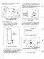
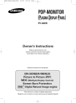
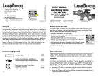
Figure
1.
Studio
II
2/CHANNEL 3
SWITCH
SOUND ON/OFF
SWITCH
(UNDER CONSOLE)
Major Assemblies
Description
GENERAL DESCRIPTION
Studio
for
home
II
console
a sophisticated,
is
microprocessor-based system
entertainment using a broadcast
TV
receiver as the
are
is
on
RF oscillator/modulator and audio circuits)
PC board. Signal information from the console
(digital,
a single
transferred to the Selector Switch Unit through a single
coaxial cable. This
display device.
Heart of the Studio
II
is
a solid-state, 40-pin integrated
same cable
computer.
It
provides central computer control for a great
variety of educational and entertainment programs.
Program
games - "Doodles", "Patterns",
"Bowling", "Freeway", and "Addition" — is included in the
console. A receptacle in the console accepts plug-in program
cartridges for many additional games such as "Tennis",
memory
for five built-in
"Baseball" and "Blackjack".
Studio
II
Selector Switch Unit
allows the
TV
the Studio
Control Console
—
Houses the keyboards and
for program selection and processing.
II
r
all
electronics
—
Forms the
interface
between the
receiver to be connected conveniently to either
or to the receiver's antenna system. This switch
- A sealed, 120 VAC to 9 VDC adapter
.8m) cord and plug that connects to a miniajack on the Switch Selector Unit. The 9
VDC is coupled to the game's 18-foot (5.5m) coaxial cable
through an RF-filtering circuit housed in the Selector Switch
ture
All electronics in the
power from the
also serves as the game's on/off switch.
with a 6-foot
consists of three major pieces:
DC
Control Console, the Studio II Power Supply Unit, the TV
receiving antenna and the TV receiver. A two-position switch
Power Supply Unit
SYSTEM DESCRIPTION
carries
Selector Switch Unit to the console to operate the electronics.
circuit microprocessor that functions as a micro-miniature
Unit.
(1
(3mm) phone
Studio
II
Servicing
The recommended Studio II service procedure is to determine whether the problem is in one of the periphery
components, the interconnecting cables or in the console
itself. If the PC board in the console is found to be faulty,
it must be returned to RCA for repair on an exchange basis.
SELECTOR
See Page 14.
SWITCH
IMPORTANT: No
attempt should be made to
adjust or repair an inoperative PC board —with
the exception of the clock-frequency adjustment
described on Page 13.
TO ANTENNA
As an aid to servicing Studio II, a test cartridge (see below)
The cartridge is not essential to service
is available from RCA.
Studio II; however, it does provide a quick and convenient
means for isolating malfunctions in the digital systems.
When a Studio II comes in for service, it is important that
you have all three assemblies: Selector Switch Unit, Power
Supply Unit and Console. If the complaint involves one or
more
POWER
\0> SUPPLY *use 75 ohm/300 ohm
transformer
if
sj
matching
required.
plug-in cartridges, these should be included as well.
SYSTEM CHECKING
Checking Studio
II
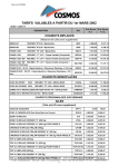
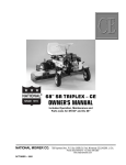
Figure
2.
Studio
II
Connection Diagram
operation can be done quickly and
from RCA (see Page 15
easily using a test cartridge available
System performance can also be
checked by operating each built-in game function; however,
this procedure takes more time than the test cartridge check.
for ordering information).
SYSTEM CONNECTIONS
Studio
of any
^J
connects to the 300-ohm VHF antenna terminals
2 describes the hookup of the three
II
TV
receiver. Figure
subassemblies. Figures 4, 5 and 6 descirbe the hookups with
typical video-tape machines and typical cable TV setups.
Recessed on the underside of the console are two slide
One switches the game sound (beeper) on or
switches (Fig. 3).
off while the other changes operating channel. Studio
II
oper-
Figure
TV Channel 3 depending on the
The switch should be set on the unoccupied channel; or areas where both channels are occupied,
on the channel with the weakest broadcast signal. Units
are shipped from the factory with the switch in Channel 3
ates
on
TV
3.
Locations of Channel Change and Sound
Channel 2 or
On/Off Switches
position of the switch.
ANTENNA
I
position.
STUDIO
.
Slide the switch
VIDEO
1".
CASSETTE
MACHINE
"Studio
1
on the Selector Switch Unit (Fig. 7) to
This sends power to the console (indicated by the
red glow of the pilot light
the
TV
receiver.
Studio
II
on the console) and connects
is
now
it
TEST PROCEDURES
Figure 4.
Press the "Clear" button
left-hand
way" and
Keyboard
A
LEAD?
^
ready for operation.
on the console and press Key 4 on
(Key A4). This
sets
Studio
the track (Fig. 8) appears immediately.
II
If
Selector
II
SELECTOR
SWITCH
BOX
TWIN
to
-^
ANTENNA
TWIN
LEAD^
TV
RECEIVER
/
TERMINALS
Switch Box Connects Between Video
Cassette Recorder and
Home
Receiver
for "Free-
necessary,
adjust the receiver's fine tuning and vertical/horizontal hold
CO -AX
controls.
CABLE
STUDIO
CATV
TUNER
.
TWIN
LEAD^
II
TWIN
SELECTOR
SWITCH
BOX
LEAo7
TV
RECEIVER
Operational Checks Test Cartridge
^ ANTENNA
(See Page 7 for procedure using built-in programs).
The
Studio
test cartridge,
II
which plugs into the cartridge
on the
console, scans the digital circuitry for trouble with a rou-
tine that takes
about 30 seconds.
If it
,
TERMINALS
slot
finds a malfunction, the fact
Figure 5. Selector Switch
and
Box Connects Between
Home
Receiver
CATV Tuner
sj
is
indicated on the
cartridge sets
up
TV
screen;
a test for the
if
there
is
no trouble, the
two keyboards.
NOTE: The Test Cartridge requires substitution
of the power unit during test. Use the special
500mA power unit (see Parts List) instead of the
original power unit.
Press and hold "Clear" button
1.
sert Tester
on Studio
II
console. In-
cartridge into slot while holding "Clear" button.
I
Insert cartridge into console with label
toward "Clear" button. Follow label directions
concerning removal of conductive rubber strip
NOTE:
Figure 8. Adjust Receiver for Sharp
"Freeway" Display
side
covering the plug.
Fig.
Release "Clear" button. A pattern similar to that of
9a appears on screen immediately, and Tester begins its
moving
scan of the system (indicated by the black streak
through the white field in the lower half of the pattern). If the
shown
pattern fails to appear or a pattern other than that
2.
I
f
appears, a faulty chip
about
In
1 1
is
PC board.
complete. The display
indicated. Replace
seconds, the
shifts to the pattern
shown
first
scan
in Fig.
is
9b with
a
white streak
field. This scan takes another 1 1 seconds. At
pattern on
the end of the second scan, the system changes the
the lower half to a series of transient vertical white lines on
scanning a black
black and then a series of black lines on white. This sequence
takes about 2 seconds. At the end of this short sequence, the
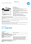
This indipattern again shifts- to that illustrated in Fig. 9c.
appearing in
all memories operational. A digit or digits
the "checkerboard" pattern in the center of the screen, as
and
in Fig. 9e, indicates chip failure in the PC board
cates
shown
r
the board must be replaced.
If the checkerboard appears as
in Fig. 9c,
touch the keys
one at a time - of Keyboard A, and then Keyboard B. As
each key switch closes, the digit on screen should change to a
checkerboard square. (If any digit remains on screen after key
actuation, the keyboard is defective and must be replaced
-
(see
Page 11).
When
all
key closures are complete (indicating
STUDIO
CATV
CO-AX
CATV
II
TV
RECEIVER
SELECTOR
SWITCH
BOX
MATCHER
ANTENNA
TERMINALS
r
Figure 6.
Selector Switch Box Connects Between
Matcher and Home Receiver
CATV Cable
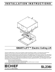
(d)
ANTENNA
TERMINALS
£1
TV -«
mmmm^m
nc/i
»- STUDIO
Operable Keyboards and Electronics
II
o
-T®~L
TO
CONSOLE
STICKY TAPE
Figure 7. Selector Switch
Box
(e)
Bad Key A7 and
Figure
9.
Tester
1
Digital Failure
Screen Patterns
!<<>£:
sj
sj
IT
laxoos
QdVO 3HV0
-M-c+-
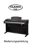
Figure 10. Overall Block Diagram of Studio
J
II
System
satisfactory
shifts to the
keyboard function), the pattern
"OK"
black-onpattern of Fig. 9d. The pattern flip-flops between
is actuated.
white and white-on-black until the "Clear" button
normally, the whole sequence
If the "Clear" button functions
completes the
starts again as the button is released. This
"Tester I"
OPPOSING CAR CONTROLLED
BY THE COMPUTER
test.
the original power unit into
the system. Store the special unit with the test
NOTE: Reconnect
cartridge for future use.
Operational Checks Using Built-in Programs
PLAYER'S CAR
The following instructions are for operating the built-in
"resident" games to evaluate Studio II performance:
Figure 13.
"Bowling" Game
Press "Clear" key. Press
r*
Key A3
"Freeway" Screen Display
(left-hand keyboard).
seconds
Screen will display "scorecard" (Fig. 11) for about 3
ball
and immediately sets up alley (Fig. 12) with bowling
moving up and down at the left side.
"Freeway" Game
Key A4; racetrack appears on screen
Key BO to start race. Press and hold Key B4 to
car to right. Press A2 to speed
steers
B6
steer car to left; Key
up race (throttle); Key A8 slows car (brake). Object: AccumPress "Clear" key. Press
(Fig. 13). Press
computer-conulate "mileage" by avoiding collisions with
PLAYER B
SCORE
PLAYER A
SCORE
ana
trolled (narrow-bodied) car in a
two-minute
race.
At the end
of the race, the screen displays the distance traveled.
noa
PLAYER B
SCORE
PLAYER A
SCORE
FRAME
NUMBER
^nm
qdsk
Figure 11. Bowling "Scorecard" Display
L
\
j
\
THREE NUMBERS TO BE ADDED
Figure 14. "Addition" Screen Display
STRAIGHT, KEY
«r5
"Addition" Function
Key A5. Screen display appears as
14. Player has five seconds to add the three
lower group and press the correct answer on Keyboard A or B. For example, the "130" on Fig. 14 adds up to
"4". Punch A3 or B3 to score. The sooner the correct total is
entered, the higher the score. (Maximum score for each entry
Press "Clear" key. Press
r
shown
in Fig.
digits in the
Figure 12. Bowling Ball Release Keys
Keyboard A is in action: Pressing A5 releases a straight
toward the pins; Key A2 sends a ball with a left (upward)
hook while Key A8 delivers a right (downward) hook (Fig. 12).
Knocking out all pins on one throw registers a strike with a
score of 20 ("ST- 20" at lower left corner of alley); two throws,
5" on screen). The scorecard reappears for
a score of 1 5 ("SP-1
about 3 seconds after the second ball is thrown or all pins are
plays right-hand Keyboard B.
then
Player
2
downed.
the keyboard "locks out"
is 11). If the wrong total is entered,
and the player gets no second chance on the on-screen comin random order.
run
in
the
20
sets
are
bination. There
"Patterns" Function
ball
Key A2. Screen remains dark.
Key B4, then Key BO. The computer then "paints" the
left and from bottom to top. Once
the matrix is all white, the computer then paints the screen
black. Press Key B5, the painting stops or freezes, press Key
Press "Clear" key. Press
Press
screen white from right to
BO, painting resumes.
—
The keys of Keyboard B "write" on the screen according
to the white arrowheads on the keyboard (Fig. 15). To form
an interesting pattern, press "Clear" key, then A2, B2 15
times, B6 once, and then BO. The memory stores up to 130
key entries or "moves". After 130 moves, the computer auto'
matically starts to repeat the pattern. For 129 or fewer moves.
Key BO must be pressed to start the repeat cycle.
—
Keyboard Tests
If
"Tester I" cartridge
malfunction.
If
Tester
is
is
I
available, use
to isolate keyboard
it
unavailable, the keyboards can be
tested using the built-in "Addition" game:
Step 1 Punch up "Addition" game (Key A5). Sound switch
must be "on".
Step 2: When the three-digit number appears on screen,
enter a series of wrong answers, beginning with A1 As each
:
.
button
is
pressed, the beeper sounds, indicating the particular
The beeper sounds only during the five
seconds that the random-order display is on screen. Usually,
button
is
operational.
the entire keyboard can be checked during the five-second
display. If any key fails to sound, that key is faulty and the
entire
keyboard should be replaced.
am
KEYBOARD A
KEYBOARD
ana
13D
B
KEY #5 START
f
I
aha
nan
B
\___
Studio
r\~~.
\
II
©
a
ni
io
B
o\po
;
PLAYER A
ENTERS
DDD
DDD
Q
l
STARTS
COMPUTER
PATTERN
DDD
DDD
]
'
DDDD
©
a
KEY#0
CLEAR
Studio 11
CLEAR
<
I
^
—
PLAYER B
ENTERS
SUM
.
Figure 17. Using "Addition" to Check Keyboards
"B" Moves Spot According to White
Arrowheads on Panel
*J
Figure 15. Keyboard
"Double-Hit" Keyboard Complaints
Some
"Doodles" Function
early production units (Serial Nos.
37125 and lower)
occasionally exhibit a keyboard malfunction termed "double-
A1 Single dot appears on screen at
lower left corner. Use keys on Keyboard B to move spot
according to white arrows on panel (Fig. 16). Key B5 leaves a
trail as player "writes" with Keyboard B. Pressing Key BO
leaves no trail. Retrace steps to erase lines already written.
Press "Clear" key. Press
.
hit"
when Studio
II
operates
in
the "Patterns"
mode
(un-
wanted dots appear on the screen, and the beeper sounds
The only remedy for double
hits is keyboard replacement.
twice for only one key entry).
Coaxial Cable Tests
The coaxial cable carries modulated RF from the console
DC from the power unit. Use an ohmmeter to test the
1 8). A good cable measures 5 to
and
cable from the plug end (Fig.
CABLE CONNECTOR
Z>««">
N s~^
—
I—/©n
OHMMETER
I
I
I
4""J
Figure 16. In "Doodles", etch a sketch electronically with the
"B" keyboard
8
Figure 18. Checking Continuity of Co-ax Cable
J
50 ohms resistance with negative ohmmeter polarity on the
center conductor. (With positive polarity on center conductor,
resistance
should be between 20 and 30k ohms.) See "Coaxial
Cable Replacement".
r
test for a
substitution with a
unavailable, use a
new
DC
result. (Late
production units use insulated rivets which
eliminate problem))
Power Supply Unit Tests
Selector Switch Unit Tests
The quickest
to the metal box or rivets holding terminal board. If either
antenna lead touches the box or rivets, snowy pictures may
troublesome Selector Switch Unit
unit (see Parts List).
voltmeter and
If
ohmmeter
circuitry (see schematic of Fig. 19) for
open
a
new
unit
is
is
to check unit
or short-circuited
components.
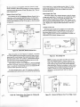
The Power Supply Unit operates between carefully chosen
voltage and ripple limits.
To check
unit for satisfactory opera-
connect unit as shown in Fig. 20. DC output under
these conditions ranges between 8.5 and 10V. Ripple on this
DC (measured with oscilloscope) must not exceed 1 V peak-totion,
peak. Replace unit
if
beyond these
specifications (see Parts
List).
TWINLEAD
TV SET
CONNECTION
GAME
A A
INPUT
Leakage Current Test
TRANSFER
SWITCH
TERMINALS
1
>-9(PHONO
JACK)
O
1-
J1
J3
N
H
<**
I
0=
1
o
TV ANTENNA
TERMINALS
r
With the Power Supply Unit plugged into an AC outlet,
check for leakage current to earth ground on both poles of
the phone plug, as shown in Fig. 21 using an AC milliammeter. Leakage current must not exceed 0.5mA. Reverse AC
,
plug polarity and recheck leakage current.
STUDIO
I
RFC 2
A A
DC INPUT
TERMINALS
(PHONE JACK)
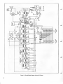
Figure 19.
Schematic, Selector Switch Unit
EARTH
GROUND
r
the "Studio II" position, it connects
the coaxial cable from the console to the twin lead and completes the DC circuit between the console and power supply.
When
the switch
is in
With the switch in the "TV" position, it disconnects the console and forms a circuit between the antenna terminals and
the twin lead for normal TV reception.
If the Selector Switch Unit is defective, it must be replaced
(see Parts List) since it cannot be satisfactorily repaired in the
RF
field. It is carefully manufactured so as not to exceed the
radiation limits specified by the
FCC.
Figure 21.
NOTE:
If
ative with operable
snowy
pictures occur in the
Leakage Test
Studio
II
OK
but
is
inoper-
console, check
fit
of
and jacks
have tolerances that conflict and prevent adequate
plug penetration. Solution to problem is often simply
to increase effective length of plug by filing the jack
plug-in jack.
slightly as
"TV" position or Studio II
cannot be shut off, check antenna connections for short circuits
If
AC
power unit checks out
Some
shown
early production plugs
in Fig.
22. (Use sharp knife to
remove any untrimmed mold
flash
from plug
if
present.)
r
FILE OR SHAVE
SLIGHTLY
TO INCREASE
PLUG PENETRATION
-ft-
\
TO 120V
AC LINE
—^
Figure 20. Testing
ADJUST FOR
250 mA ON
MILLIAMMETER
Power Unit Output for Voltage and
Ripple Content
Figure 22.
Removal of Material from Front Edge of Jack
^J
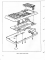
Figure 23. Studio
10
II
Console Assembly
CONSOLE DISASSEMBLY
The console
3.
halves of the cabinet, printed circuit board,
and
r
a
two
two keyboards,
consists of six separate subassemblies: the
Release the keyboard from the console by unlatching
two brown colored
latches as illustrated.
Keyboard
now
is
free of console.
"Clear" switch/power-on indicator.
The upper and lower halves of the cabinet are separated
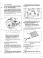
by removing 5 Phillips-head screws. With the bottom cover removed, the underside of the printed circuit board is exposed.
Lift the PC board up at the cartridge socket side as shown in
Fig. 24. This
exposes the component side of the board. The
board stands on edge if set between pillar (near "Clear" switch)
and flange of cabinet upper half as shown.
CARTRIDGE
RODE
^
—
"***
^k^===^
'^A
*
x%
Figure 25. Releasing Keyboard from Console
new keyboard by feeding ribbon cable through
opening in console before latching keyboard in place.
5. Push ribbon cable into connector.
4. Install
\$
NOTE: Some
S
V/^/^^^^^
X^Ss^^
]
"^-^
\^^
center
SL0T
in
II
units use unenclosed rib-
the connector so that
leads contact
all 1
1
fails
to
for proper operation.
"\°
6. If
~
PC Board
in
ribbon cable from keyboard
make good contact
in connector, trim back 1/16 inch from edge with ordinary
household scissors to expose fresh contact.
TOP HALF
OF CABINET
Figure 24.
Studio
bon connectors on PC board. Ribbon cable must
CART
SOCKET
Wiring Access Position
NOTE: The channel-change and sound
on/off
switches, plug-in cartridge connector and other
components mounted on the PC board
field replaceable. All
PC board
are not
faults (except
speaker) require board exchange.
CAUTION: Tuner
sprays containing silicon must not
be used on slide switches. Irrepairable switch dam-
r
age will result.
COMPONENT REPLACEMENT PROCEDURE
Figure 26.
PC Board Removal
Disconnect black, white and yellow wires from board; unfrom board and carefully pull out keyboard ribbon leads from RC board connectors. See "PC Board
Packing and Shipment" for board exchange details (Page 14).
solder coaxial cable
Trim Ribbon Cable with
Damaged Edge
Coaxial Cable Replacement
1
Remove bottom
.
shield covering
wiring on
Keyboard Replacement
1.
Keyboard replacement requires console disassembly
as
r*
Unplug the ribbon cable of the defective keyboard from
the ribbon connector on the PC board by pulling the ribbon
2.
straight out of the connector.
Pry carefully so as not to damage
PC
foil
board.
Disconnect cable by unsoldering shield
2.
overheat
first.
Do
not
foil.
3. Install
lead
half of console cabinet. Pry off metal
end of coaxial cable.
CAUTION:
described above.
Scissors to Repair
replacement cable as shown by soldering center
first.
4. Re-install shield
cover carefully and firmly. Center coaxial
11
cable in slot
cover (Fig. 27). Shield
in
minimize radiation of modulated
must be
fully seated to
carrier.
4. From underside of cover, bend clipped pigtails back and
collapse black plastic holder with needlenose pliers or diagonal
cutters. Remove holder from console holes using pliers or
cutter.
5. Install
new LED
console cover until
it
holder. Press holder gently into hole in
sJ
clicks into place (Fig. 29).
*
Figure 27. Disconnect
Co-Ax Shield
First to
J
Replace Cable.
Resolder Center Lead First on Installation.
Do Not Overheat Foil in Board.
Figure 29. Cross-Sectional
View of Seated LED Holder
in
Console Cabinet
LED
indicator Replacement
NOTE:
Installing a
new LED
in
the console
re-
6. Place
quires the use of a special tool that can be fabri-
pigtail
cated from a piece of sheet metal with a sabre
saw. See Fig. 28 for dimensions.
and 31
*m
new LED
LED
in
holder with shorter (cathode)
toward side connected to "Clear" switch (see Fig. 30
). This is important — indicator cannot light if con-
M
5.75-
j
CATHODE (-) PIGTAIL
SHORTER THAN ANODE
I
/
-
d
I
+
MATERIAL:
0.050
2
O
3
'
ALUMINUM
OR STEEL
Figure 30. Polarity Marking
on LED
z
2
-.
I
I
0.26"
I
-»»j o.2rj-«-
Figure 28.
1
.
T
LED Replacement Tool
+
f¥
^
!
T>
/
>
YELLOW
WIRE
<r_
*
n
PLASTIC PILLAR
(PART OF CONSOLE CABINET)
Unsolder the black and white leadwires from "Clear"
switch terminals and unsolder the yellow wire from the LED
pigtail. This frees the console top half for LED replacement.
2.
3.
LED
12
Snip both LED pigtails off close to the LED.
Place console cover, face up, on block and drive out old
with small screwdriver or 1/8-inch drift pin.
,>
Figure 31. Indicator Assembly
.
nected with reversed polarity. Use fabricated tool (Fig. 28) to
push LED into holder. LED "clicks" into place. Any tool
without a shoulder usually pushes LED out of the holder.
r
7. Form snipped leadwires as shown in
new LED pigtails to them. Solder quickly
heating
8.
Fig.
31 and connect
to prevent over-
LED.
Reconnect black, white and yellow leads from PC board
to complete installation.
CLOCK FREQUENCY ADJUSTMENT PROCEDURE
Incorrect clock frequency adjustment causes pattern weave
on screen. This results from a beat note between the vertical
sync rate of Studio II and the hum frequency in the TV receiver. If the beat note is more than 0.5 Hz, the weave becomes
noticeable to the critical user. Clock frequency is a slug adjusts
ment on the PC board.
1
Connect scope probe to the junction of two resistors as
shown in Fig. 34. Connect scope ground to RF shield, cartridge
post or to other suitable board ground.
Adjust scope time base for a total sweep length of 20
more (sync on "Line") and vertical input
2.
TO PC BOARD
BLK .
milliseconds or
WHT
about 250 mV/cm (0.625 V/in).
Push "Clear" button on console and adjust slug slowly
waveform drift. See Fig. 33. Guard against overadjust-
sensitivity for
3.
for zero
ment.
r
L,
f
Figure 32. Power-On Indicator Wiring
V1WWVWWWWL
(VERTICAL SYNC INTERVAL)
W
'
Waveform Used to Adjust Clock Frequency.
Scope Time-Base Locked to 60Hz Power Line
Figure 33.
r
r
Figure 34.
Scope Connections for Adjusting Clock Frequency
r
13
PC Board Exchange
EXCHANGE PLAN DESCRIPTION
RCA operates a PC board refurbishing facility
at
Swannanoa,
North Carolina. Defective PC boards sent to this facility are
5.00*
refurbished and returned to the sender at a cost of $1
provided, of course, the exchange board is repairable.
PC
sure board
is
filler as shown and pack in carton.
check or money order for $15.00*. A refurbished
be shipped to the address you supply on the
questionnaire packed with defective board.
4. Include
PC board
completely sur-
5.
rounded with cushion to prevent shipping damage
that might make board useless for exchange. Be
sure to include a completed questionnaire (from
Page 15)
in
will
Ship prepaid (Parcel Post or UPS) to:
Studio II PC Board Refurb. Dept.
RCA Distributor & Special Products Div.
Old Bee Tree Road
Swannanoa, North Carolina 28778
the package.
Pack defective PC board in foam shipping container as
shown. Note relative positions of PC board components and
1
^/
of upper corrugated
NOTE: If custom shipping container described
below is not available, pack PC board in cushion of
crumpled newspapers or "bubble pack" in suitably
Make
of one to another.
2. Pack foam enclosure in carton. Use crumpled news-
papers as cushion around foam enclosure.
3. Fill in all blanks on questionnaire, particularly those
indicating abnormal symptoms (questionnaire packed with
refurbished board). Pack completed questionnaire on outside
BOARD PACKING AND SHIPMENT
sized carton.
the molded-in supports in the foam plastic. If two halves
of foam packing fail to mate easily, reverse relative position
^^
.
*Price subject to change without notice.
QUESTIONNAIRE
CRUMPLED
NEWSPAPER
CORRUGATED
BOARD
J
Figure 35. Packing
PC Board
in
Foam
Figure 36. Packing
Container
Studio
II
RCA
2
PC Board
2
Coaxial Cable Assembly
1
Selector Switch Assembly
1
3
1
Parts Distributors as Stock No.
Description
Quantity
(less
coaxial cable)
Power Supply Unit
Keyboard Assembly
Includes reusable shipping carton for each board
*Price subject to change without notice.
14
Container
in
Carton
Service Parts Kit
Service organizations desiring to stock service replacement
parts may order a kit of Studio II replacement parts and
assemblies through
Foam PC Board
199047. Cost for the entire kit is $99.95* - as compared with
$122.90* for the 20 individual pieces. The kit
v
a total of
includes:
Stock No.
742463
742421
18V102
18V101
742458
1
Description
Quantity
2
2
Speaker
3
3
"Clear" Switch
1
LED Power
Indicator (Incl. Holders)
Pushbutton for "Clear" Switch
Set of 4 Console Rubber Feet
Stock No.
742448
742461
742459
742460
742462
J
STUDIO
1
r
s
C/3
II
PC
BOARD EXCHANGE QUESTIONNAIRE
1
Please pack completed questionnaire in container with defective board with check or
1
(Price subject to
change without notice.)
Please describe defect
1
Studio
Serial
II
money order
for $15.
Nn
symptom (s). (Nodisplay,
no sound,
partial display,
1
<
etc.)
RETURN SHIPPING LABEL
I
he?
z:
Firm
Name
o
_i
<
Firm Address
i-
o
Intermittent
Defect:
|
STUDIO
J
LLi
(Price subject to
_l
00
I
~
Attn:
II
PC
BOARD EXCHANGE QUESTIONNAIRE
Please pack completed questionnaire in container with defective board with check or
,
change without notice.)
Please describe defect
|
partial display,
Zip
Continuous
Note: For in-warranty board exchange, include
RCA Form PA737 "Repair Report".
'
r
State
Pity
Studio
I!
money
order for $15.
No
Serial
symptom (s). (Nodisplay,
no sound,
etc.)
RETURN SHIPPING LABEL
|
o
o
<
Firm
h-
Firm Address
Name
O
State
City
1
Defect:
Intermittent
RCA Form PA737
|
7ip
Continuous
Attn:
Note: For in-warranty board exchange, include
"Repair Report".
Replacement Parts and Accessories
Stock No.
Description
r
PC Board
in
(less
coaxial cable, packed
reusable shipping carton)
Cable Assembly
Power Unit Assembly
(incl.
cord and plug)
Speaker, 2.24-inch diameter
18V102
742458
742448
LED
742461
Selector Switch Assembly
Keyboard Assembly
Indicator (incl. plastic holder)
"Clear" Switch
2
742463
742421
18V101
742459
Stock No.
Description
742460
742462
5009339
5008333
Pushbutton for "Clear" Switch
Rubber Feet (Package of 4)
"Tester I" Test Cartridge 2
Power Unit (for use with "Testei 1")
(Dwg. No. 1809952)
Console Housing, Upper Half
(Dwg. No. 1809951)
Console Housing, Lower Half
Dress Plate (LED Indicator and 'Clear" button)
(Dwg. No. 1808321-1)
'
Dress Plate ("Studio II")
(Dwg. No. 1808319-1)
Requires special power unit Stock No. 5008333
r*
15
^
^
"j
3
Printed
RCA
|
Distributor
and Special Products Division Deptford NJ 08096
|
Tmk(s)
®
Marca(s) Registrada(s)
in
U.S.A. 11/77
Form 3E4589
J