1
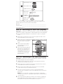
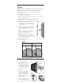
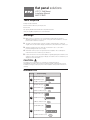
flat panel solutions
LCD TV Wall Mount
Installation Manual
MAF121BKR
Tools Required
Phillips Head Screw Driver
Part 2 - Attaching t
Display
Important! Use extra care during the
placing your display facedown as it m
Note: Your mount comes with a sele
accommodate a wide variety of displa
in the kit will be used.
1.
Ratchet or Driver with 1/2” (13 mm) Socket
Determine the correct length of b
examining the back of your displa
Electric Drill
A. If your display has a flat back
G, or J) from the hardware kit.
1/4” (6 mm) Drill Bit and Stud Finder for Drywall Installation
B. If your display has a curved o
7/16” (11 mm) Masonry Bit for Concrete Installation
Warnings
1.
Make sure these instructions are read and thoroughly understood before
attempting installation. If you are unsure of any part of this installation, contact a
professional installer for assistance.
2.
The wall or mounting surface must be capable of supporting the combined
weight of the mount and the display; otherwise the structure must be reinforced.
3.
Safety gear and proper tools must be used. Failure to do so can result in
property damage and/or serious injury.
4.
A minimum of two people are required for this installation. Do not attempt to
install this mount alone under any circumstance.
5.
Follow all instructions and recommendations regarding adequate ventilation and
suitable locations for mounting your display. Consult the owner‘s manual for your
display for more information.
CAUTION:
This wall mount is intended for use only with the maximum weight of
36 kg/80 lbs. Use with heavier than the maximum weights indicated may result in
instability causing possible injury. Follow the installation and operation instructions
carefully.
longer bolts (B, E, H, or K) along
2.
Determine the correct diameter o
carefully trying one bolt each from
the hardware kit. Do not force an
if you feel resistance stop immed
smaller diameter bolt.
3.
Attach the arms to the back of yo
using the bolts identified in Steps
with the corresponding Lock Wa
L) (see Fig. 2 and 3).
A. If you are using the M4, M5, o
(Bags 1, 2, and 3 respectively), y
need to use the M6 Washers (O).
B. If you are using one of the lon
a display with a curved or recess
will also use a Spacer (M or N). U
Spacer (M) for M4 and M5 bolts
Spacer (N) for M6 and M8 bolts.
4.
Fig. 3
For displays with flat b
Hardware Kit
Bag#
Make sure all screws are secure,
do not over-tighten them.
(Ref) Item (Qty)
(A) M4x12 Bolt (x4)
1
(B) M4x30 Bolt (x4)
(C) M4 Lock Washer (x4)
(D) M5x12 Bolt (x4)
2
(E) M5x30 Bolt (x4)
(F) M5 Lock Washer (x4)
(G) M6x12 Bolt (x4)
3
(H) M6x35 Bolt (x4)
Part 3 - Final Instal
1.
With the help of another
person, carefully lift your
display and place it on mount
(see Fig. 4). Place the display
in the middle of the mount,
and do not release the display
until the mounting arms have
securely hooked onto the
crossbars.
2.
Important! Move the safety
tab located on each arm into
position to avoid having the
display accidentally lifted from
the mount. A padlock can be
inserted into one of the tabs
to help prevent theft of your
(I) M6 Lock Washer (x4)
(J) M8x16 Bolt (x4)
4
(K) M8x40 Bolt (x4)
(L) M8 Lock Washer (x4)
(L) M8 Lock Washer (x4)
the mount. A padlock can be
inserted into one of the tabs
to help prevent theft of your
display (see Fig. 5).
(M) Small Spacer (x4)
5
(N) Large Spacer (x4)
(O) M6 Washer (x4)
3.
Use the cable management
hooks to help keep your powe
cord and other cables in order.
4.
Side-to-side and front-to-back
adjustments can be made by
firmly grasping your display
and carefully moving it to the
desired position.
5.
If any of the arms become
too lose to hold their position,
they can be tightened using
the Alley Key provided in your
hardware kit (see Fig. 6).
6.
To adjust the tilt position of you
in place while another person l
on either side of the mount (se
display to the desired angle. Ti
display. NOTE: The tilt adjustm
to change the position of the k
simply pull the knob out before
(P) Concrete
Anchor (x4)
6
(Q) M8x63
Lag Bolt (x4)
(R) M6 Lag Bolt
Washer (x4)
Keep your sales receipt to obtain warranty parts and service and for proof of
purchase. Attach it here and record the model number.
Model No. _____________________________________________________________
Purchase Date: _________________________________________________________
Dealer/Address/Phone __________________________________________________
Part 1a - Mounting the Wall Plate (Drywall)
Limited Lifetime Wa
Important! For safety reasons, this mount must be secured to a wood stud and the
stud must be capable of supporting the combined weight of the mount and display.
Audiovox Electronics Corporation (
retail purchaser of this product that
be proven defective in material or w
it, such defect(s) will be repaired or
charge for parts and repair labor. T
of this Warranty, the product is to b
(e.g. dated bill of sale), specification
Company at the address shown be
1.
Using a high quality stud finder, locate and mark one stud for securing the
mount.
2.
With the help of another person, place the mount against the wall over the
marked stud. Make sure the mount is level.
3.
While another person holds the mount in place, mark two locations on the wall
where the mount is to be installed.
Fig.1
Be sure to use the center of the
stud.
4.
Set the mount aside and drill a
1/4” (6 mm) pilot hole at each
marked location.
5.
Place the mount back against the
wall and secure it using the Lag
Bolts (Q) and Lag Bolt Washers
(R) provided (see Fig. 1). Do not
over-tighten these bolts and do
not release the mount until all
bolts are in place
Part 1b – Mounting to the Wall (Concrete)
Important! For safety reasons, the concrete wall must be capable of supporting
the combined weight of the mount and display.
1.
With the help of another person, place the mount against the wall in the
desired location and make sure it is level.
2.
While another person holds the mount in place, mark at least two locations
on the wall where the mount is to be installed.
3.
Set the mount aside and drill a 7/16” (11 mm) pilot hole at each marked
location. Remove any excess dust from the holes.
4.
Insert a Concrete Anchor (P) into each hole so that it is flush with the
concrete surface. A hammer can be used to lightly tap the anchors into place
if necessary.
NOTE: If the concrete wall is covered by a layer of plaster or drywall, the
concrete anchor must pass completely through the layer to rest flush with the
concrete surface.
5.
Place the mount back against the wall and secure it using the Lag Bolts (Q)
and Lag Bolt Washers (R) provided (see Fig. 1). Do not over-tighten these
bolts and do not release the mount until all bolts are in place.
This Warranty does not cover prod
United States or Canada.
This Warranty is not transferable an
installation, removal or reinstallation
if in the Company’s opinion, the pro
improper installation, mishandling,
OF THE COMPANY’S LIABILITY UN
REPAIR OR REPLACEMENT PROV
COMPANY’S LIABILITY EXCEED T
FOR THE PRODUCT.
This Warranty is in lieu of all other e
WARRANTIES, INCLUDING ANY IM
OR FITNESS FOR A PARTICULAR
OF THIS WARRANTY. IN NO CASE
ANY CONSEQUENTIAL OR INCIDE
or representative is authorized to a
than expressed herein in connectio
provinces do not allow limitations o
the exclusion or limitation of inciden
limitations or exclusions may not ap
legal rights and you may also have
state/province.
U.S.A.: Audiovox Electronics Corpo
Hauppauge, New York 11788
CANADA: Audiovox Return Center,
16, Mississauga, Ontario L5T 3A5
Trademark(s) Registered
All other brands and product name
their respective owners.
© 2011 Audiovox Accessories Corp
www.rcaaudiovideo.co
anel solutions
Wall Mount
n Manual
KR
Note: Your mount comes with a selection of bolt diameters and lengths to
accommodate a wide variety of display models. Not all of the hardware
in the kit will be used.
ocket
or Drywall Installation
ead and thoroughly understood before
unsure of any part of this installation, contact a
e.
Determine the correct length of bolt to use with your display by first
examining the back of your display.
2.
3.
t be used. Failure to do so can result in
njury.
G, or J) from the hardware kit.
Perceuse électrique
B. If your display has a curved or recessed back, you will use one of the
Foret de 6 mm (1/4 po) et localisateur de montants
Determine the correct diameter of bolt to use by
carefully trying one bolt each from Bags 1 - 4 of
the hardware kit. Do not force any of the bolts –
if you feel resistance stop immediately and try a
smaller diameter bolt.
Avertissements
Fig. 2
Attach the arms to the back of your display
using the bolts identified in Steps 1 and 2 along
with the corresponding Lock Washer (C, F, I, or
L) (see Fig. 2 and 3).
(Bags 1, 2, and 3 respectively), you will also
need to use the M6 Washers (O).
B. If you are using one of the longer bolts on
a display with a curved or recessed back, you
will also use a Spacer (M or N). Use the Smaller
Spacer (M) for M4 and M5 bolts and the Large
Spacer (N) for M6 and M8 bolts.
mendations regarding adequate ventilation and
ur display. Consult the owner‘s manual for your
4.
Tournevis à tête cruciforme
Cliquet ou clé à douille de 13 mm (1/2 po)
A. If you are using the M4, M5, or M6 bolts
uired for this installation. Do not attempt to
circumstance.
Outils nécessaires
A. If your display has a flat back, you will use one of the shorter bolts (A, D,
longer bolts (B, E, H, or K) along with a spacer (M or N).
t be capable of supporting the combined
ay; otherwise the structure must be reinforced.
ly with the maximum weight of
e maximum weights indicated may result in
ow the installation and operation instructions
Support mural
Manuel d'insta
MAF121BKR
Important! Use extra care during the part of the installation. If possible, avoid
placing your display facedown as it may damage the viewing surface.
1.
te Installation
solutions
Part 2 - Attaching the Arms to the
Display
Foret de maçonnerie 11 mm (7/16 po) pour insta
1.
S’assurer de lire et de comprendre entièrem
d’essayer toute installation. En cas de doute
de l’installation, contacter un entrepreneur o
assistance.
2.
Le mur ou la surface de montage doit être c
support et de l'écran, dans le cas contraire,
3.
Il est obligatoire d'utiliser des accessoires d
Le non-respect de cette consigne peut prov
blessures graves.
4.
Il faut au moins deux personnes pour effect
essayer d'installer ce support tout seul.
5.
Suivre toutes les instructions et recommand
adéquate et les emplacements adaptés pou
manuel de l'utilisateur de l'écran concerné p
MISE EN GARDE :
Make sure all screws are secure, but
do not over-tighten them.
Ce support mural est conçu pour supporter un
Son utilisation avec un poids supérieur au maxim
l’instabilité et des blessures. Respectez soigneu
et d’utilisation.
Fig. 3
For displays with flat backs... For displays with curved or
recessed backs
Trousse d’installation
N° de
paquet
(Qty)
Article (réf) (Qté
(A) Boulon M4 x12 (x4)
)
1
4)
(B) Boulon M4 x 30 (x4)
(C) Rondelle de blocage
er (x4)
(D) Boulon M5 x12 (x4)
2
)
(F) Rondelle de blocage M
er (x4)
)
)
Part 3 - Final Installation and Adjustment
1.
r (x4)
)
4)
2.
her (x4)
(x4)
(x4)
4)
(E) Boulon M5 x 30 (x4)
3
With the help of another
person, carefully lift your
display and place it on mount
(see Fig. 4). Place the display
in the middle of the mount,
and do not release the display
until the mounting arms have
securely hooked onto the
crossbars.
Important! Move the safety
tab located on each arm into
position to avoid having the
display accidentally lifted from
the mount. A padlock can be
inserted into one of the tabs
to help prevent theft of your
display (see Fig. 5).
3.
Use the cable management
hooks to help keep your power
cord and other cables in order.
4.
Side-to-side and front-to-back
(G) Boulon M6 x 12 (x4)
(H) Boulon M6 x 35 (x4)
Fig. 4
(I) Rondelle de blocage M
(J) Boulon M8 x 16 (x 4)
4
(K) Boulon M8 x 40 (x 4)
(L) Rondelle de blocage
Fig. 5
Fig. 6
(M) Petite entretoise (x 4
5
(N) Grande entretoise (x
(O) Rondelle M6 (x 4)
cord and other cables in order.
4.
5.
6.
ervice and for proof of
r.
_______________________
_______________________
(O) Rond
Side-to-side and front-to-back
adjustments can be made by
firmly grasping your display
and carefully moving it to the
desired position.
Fig. 7
(P) Che
béton (x
If any of the arms become
too lose to hold their position,
they can be tightened using
the Alley Key provided in your
hardware kit (see Fig. 6).
6
(R) Rond
tire-fond
To adjust the tilt position of your display, have one person hold the display
in place while another person loosens the two tilt adjustment knobs located
on either side of the mount (see Fig. 7). Once the knobs are loose, move the
display to the desired angle. Tighten the knobs securely before releasing the
display. NOTE: The tilt adjustment knobs have a ratchet feature. If you need
to change the position of the knob without tightening or loosening the screw,
simply pull the knob out before moving it.
_______________________
Limited Lifetime Warranty
ecured to a wood stud and the
ght of the mount and display.
Audiovox Electronics Corporation (the “Company”) warrants to you the original
retail purchaser of this product that should it, under normal use and conditions,
be proven defective in material or workmanship during its lifetime while you own
it, such defect(s) will be repaired or replaced (at the Company’s option) without
charge for parts and repair labor. To obtain repair or replacement within the terms
of this Warranty, the product is to be delivered with proof of warranty coverage
(e.g. dated bill of sale), specification of defect(s), transportation prepaid, to the
Company at the address shown below. Do not return this product to the Retailer.
against the wall over the
ark two locations on the wall
This Warranty does not cover product purchased, serviced or used outside the
United States or Canada.
This Warranty is not transferable and does not extend to costs incurred for
installation, removal or reinstallation of the product. This Warranty does not apply
if in the Company’s opinion, the product has been damaged through alteration,
improper installation, mishandling, misuse, neglect, or accident. THE EXTENT
OF THE COMPANY’S LIABILITY UNDER THIS WARRANTY IS LIMITED TO THE
REPAIR OR REPLACEMENT PROVIDED ABOVE AND, IN NO EVENT, SHALL THE
COMPANY’S LIABILITY EXCEED THE PURCHASE PRICE PAID BY PURCHASER
FOR THE PRODUCT.
Wall (Concrete)
t be capable of supporting
against the wall in the
Conserver la facture comme pre
et toute réparation couverte par
modèle.
Numéro de modèle : _________
Date d'achat : _______________
Concessionnaire/adresse/télép
Plate (Drywall)
one stud for securing the
This Warranty is in lieu of all other express warranties or liabilities. ANY IMPLIED
WARRANTIES, INCLUDING ANY IMPLIED WARRANTY OF MERCHANTABILITY
OR FITNESS FOR A PARTICULAR PURPOSE SHALL BE LIMITED TO DURATION
OF THIS WARRANTY. IN NO CASE SHALL THE COMPANY BE LIABLE FOR
ANY CONSEQUENTIAL OR INCIDENTAL DAMAGES WHATSOEVER. No person
or representative is authorized to assume for the Company any liability other
than expressed herein in connection with the sale of this product. Some states/
provinces do not allow limitations on how long an implied warranty lasts or
the exclusion or limitation of incidental or consequential damage so the above
limitations or exclusions may not apply to you. This Warranty gives you specific
legal rights and you may also have other rights which vary from state/province to
state/province.
Première partie
murale (cloison
Important! Pour des raisons d
en bois et le montant doit être c
l’écran.
1.
Utiliser un localisateur de m
montant sur lequel fixer le s
2.
Avec de l’aide, placer le sup
S’assurer que le support es
3.
Alors qu’une autre personn
maintient le support en plac
marquer deux emplacemen
mur d’installation. S’assurer
le centre du montant.
4.
Mettre le support de côté e
un avant-trou de 6 mm (1/4
chaque emplacement marq
5.
Placer le support contre le
fixer au moyen de tire-fond
rondelles pour tire-fond (R)
(voir Fig. 1). Ne pas trop les
ne lâcher le support qu'une
derniers en place.
Partie 1b – Mont
Important! Pour des raisons d
supporter le poids total du supp
1.
ark at least two locations
U.S.A.: Audiovox Electronics Corporation, 150 Marcus Blvd.,
Hauppauge, New York 11788
2.
hole at each marked
CANADA: Audiovox Return Center, c/o Genco, 6685 Kennedy Road, Unit 3, Door
16, Mississauga, Ontario L5T 3A5
3.
Trademark(s) Registered
All other brands and product names are trademarks or registered trademarks of
their respective owners.
4.
at it is flush with the
y tap the anchors into place
f plaster or drywall, the
he layer to rest flush with the
it using the Lag Bolts (Q)
o not over-tighten these
re in place.
(Q) TireM8 x 63
© 2011 Audiovox Accessories Corporation
www.rcaaudiovideo.com
MAF121BKR_US_IB_00
5.
Avec de l’aide, placer le sup
s'assurer de sa mise à nivea
Alors qu’une autre personn
emplacements ou plus sur
Mettre le support de côté e
chaque emplacement marq
Insérer une cheville à béton
la surface du béton. Si néce
doucement sur les chevilles
REMARQUE : Si le mur en
plaques de plâtre, la chevill
affleurer la surface en béton
Placer le support contre le
rondelles pour tire-fond (R)
lâcher le support qu'une foi