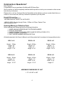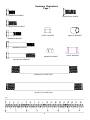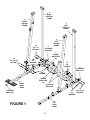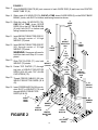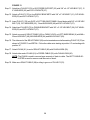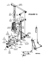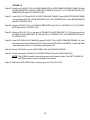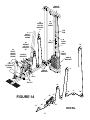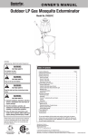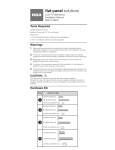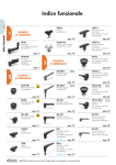
1
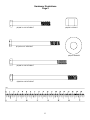
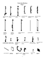
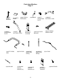
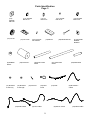
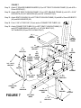
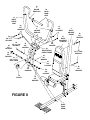
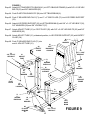
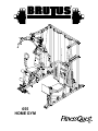
655
HOME GYM
Congratulations on purchasing your
Brutus® 655 Home Gym
With this product in your home, you have everything you need to start your own workout program to tone
and firm the major muscle groups of your upper and lower body. This is vital for all of us, regardless of age,
sex, or fitness level, and regardless of whether your primary goal is toning, health maintenance, or more
energy for daily activities.
Proper exercise, including a low fat diet, strength training and aerobic exercise, tones and conditions the
muscles we use every day to stand, walk, lift, and turn. It can actually transform our body composition by
reducing body fat and increasing the proportion of lean muscle in our bodies.
Be sure to read through this Owner’s Manual carefully. It is the authoritative source of information
about your Brutus® 655 Home Gym.
Retain this manual for future reference.
Table of Contents:
Important Safety Instructions.....................................................3
Comments or Questions & Carton Information....................................4
Hardware Illustrations........................................................................5 - 6
Parts Identification.............................................................................7 - 9
Parts List................................................................................................10
Assembly Instructions....................................................................12 - 35
Owner’s Purchase Record..........................................Back Cover
2
IMPORTANT SAFETY INSTRUCTIONS
Read all instructions before using this machine.
CAUTION: Exercise of a strenuous nature, as is customarily done on this equipment,
should not be undertaken without first consulting a physician. No specific health
claims are made or implied as they relate to the equipment. Measurements
made by the equipment are believed to be accurate, but only the measurements of your physician should be relied upon
1. Know your heart rate and / or pulse, and your physician recommended target heart rate training
zone.
2. Proper medical clearance is recommended for anyone beginning and exercise program especially
if you are over 35 years of age or suffer from heart respiratory problems.
3. Warm up before any exercise programs with 8 minutes of aerobic activity, followed by stretching
from head to toe.
4. Wear comfortable clothes that allow freedom of movement and that are not tight or restricting.
5. Wear comfortable shoes made of good support with nonslip soles.
6. Breathe naturally, never holding your breath during an exercise.
7. Perform exercises consistently with proper technique and pass through a full range of motion.
8. Always use a spotter for safety.
9. Avoid over training. You should be able to carry on a conversation while exercising.
10. After an exercise session, cool down with slow stretching, cycling or walking.
11. This machine should not be used by or near children.
12. Invalids, or disabled persons must have medical approval before using this machine and should be
under close supervision when using any exercise equipment.
13. Use this machine only for its intended use as described in this manual. Do not use attachments not
recommended by the manufacturer.
14. Do not put hands, feet, or any foreign objects on or near this machine when in use by others.
15. Always use this machine on a level surface.
16. Never operate the machine if the machine is not functioning properly.
17. Start exercise slowly and gradually increase the amount of resistance.
18. If the user experiences dizziness, nausea, chest pain, or any other abnormal symptoms, stop exercising at once and consult a physician immediately.
KEEP THESE INSTRUCTIONS
3
Comments or Questions?
Dear Customer,
Congratulations on your purchase of the Brutus® 655 Home Gym.
We’re sure that you will be completely satisfied with the product we invite your comments so that we can
hear about your success.
Please write or call our Customer Service Specialists at the address or phone number listed below, or
contact us on our web site, with any comments or questions you may have.
Brutus® 655 Home Gym
Customer Service Department
1400 Raff Road SW, Canton, OH 44750-0001
1-800-321-9236, Monday through Friday - 9:00am to 4:30pm, Eastern Time
www.fitnessquest.com
Ordering Missing or Defective Parts
When ordering parts, always provide the following information:
1.
2.
3.
4.
5.
NAME, MAILING ADDRESS AND TELEPHONE NUMBER
DATE OF PURCHASE
WHERE PRODUCT IS PURCHASED (NAME OF RETAIL STORE, CITY)
MODEL NUMBER (EHG00655)
PART ORDER NUMBER AND DESCRIPTION
All details depicted in this Owner’s Manual, and of the product itself, are subject to change without notice.
BOX 1 of 6
BOX 2 of 6
BOX 3 of 6
Weight - 179 lbs.
Length - 52”
Width - 28”
Height - 7-1/2”
Weight - 205 lbs.
Length - 81”
Width - 21”
Height - 8-1/2”
Weight - 100 lbs.
Length - 11”
Width - 5-1/2”
Height - 12-1/2”
BOX 4 of 6
BOX 5 of 6
BOX 6 of 6
Weight - 100 lbs.
Length - 11”
Width - 5-1/2”
Height - 12-1/2”
Weight - 100 lbs.
Length - 11”
Width - 5-1/2”
Height - 11-1/4”
Weight - 50 lbs.
Length - 11”
Width - 5-1/2”
Height - 6”
ASSEMBLED DIMENSIONS OF UNIT
L 73” x W 100” x H 85”
4
Hardware Illustrations
Page 1
(49)M8X15 HEX BOLT
(47)M10x25mm SCREW
(50)3/8"x3/4" HEX BOLT
(67)3/8" LOCKNUT
(46)13mm BUSHING
(48)M8X25 HEX BOLT
(52)M8X63 HEX BOLT
(69)M8mmLOCKNUT
(53)3/8"x2-5/8" HEX BOLT
(60)5/8"x5-3/4" SHAFT BAR
(61)5/8"x7-3/4" SHAFT BAR
mm
5
(70)3/4" BUSHING
Hardware Illustrations
Page 2
(56)3/8"x3-1/2" HEX BOLT
(66)5/8" LOCKNUT
(57)3/8"x4-1/2" HEX BOLT
(65)5/8" WASHER
(58)3/8"x5-1/8" HEX BOLT
(59)3/8"x6-1/8" HEX BOLT
mm
6
Parts Identification
Page 1
(1)RIGHT BASE
BEAM
(3)RIGHT
VERTICAL
FRAME
(2)RIGHT OBLIQUE (6)LEFT BASE
FRAME
BEAM
(4)LEFT
OBLIQUE
FRAME
(11)RIGHT TOP (12)LEFT TOP
CROSS FRAME CROSS FRAME
(17)FOAM ROD
(18)SEAT
CUSHION
(7)CENTER BASE
TUBE (A)
(5)LEFT VERTICAL
FRAME
(13)RIGHT SEAT
CUSHION
FRAME
(8)CENTER BASE
TUBE (B)
(9)GUIDE ROD
(14) LEG EXTENSION
FRAME
(19)RIGHT PRESS
ARM
(20)RIGHT BENCH
PRESS
FRAME
7
(10)TOP CROSS
FRAME
(36)SHROUD
(15)LEFT SEAT
CUSHION FRAME
(21) ADJUST
TUBE
(16)CONNECTOR
TUBE
(22)FOOT
PLATE
Parts Identification
Page 2
(23)LEG
PRESS
SUPPORT
(27)RIGHT
ADJUSTABLE
PLATE
(24)SAFETY
CLASP
(30)LEFT
BUTTERFLY ARM
(34)LEFT PRESS
ARM
(38)CURL BAR
(25)BUTTERFLY
EXTENSION
(35)STOP ROD
(39)DOUBLE
PULLEY
BRACKET(A)
(26)HANDLE
(31)RIGHT
BACKREST
CUSHION
(40)DOUBLE
PULLEY
BRACKET(B)
(43)WEIGHT
SELECTION
ROD(B)
(28)RIGHT
BUTTERFLY ARM
(33)LEFT BENCH
PRESS FRAME
(32)PIVOT PULLEY
BRACKET
(42)WEIGHT
SELECTION
ROD(A)
8
(29)LEFT
ADJUSTABLE
PLATE
(37)LAT BAR
(41)LEFT
BACKREST
CUSHION
(44)WAIST BAND
Parts Identification
Page 3
(72)2"
SQUARE
END CAP
(76) PULLEY
(77)TOP PLATE
(82)RUBBER
DONUT
(83)FOAM ROLL
(87) BUSHING
PLASTIC(A)
(73)1"x2"
END PLUG
(71)2" SQUARE
END PLUG
(88) BUSHING
PLASTIC(B)
(93)UPPER CABLE
(78)7/16"ALLEN
CAP SCREW
(79)WEIGHT
(85)SHORT FOAM
GRIPS
(89) POP PIN
(90)CHAIN
HOOK
(80)PRESS BAR PIN
(84) LONG FOAM
GRIPS
(91)CHAIN
(68)SQUAT CABLE
(94) LEG CABLE
9
(75)2" ROUND
END PLUG
(74)1" ROUND
END PLUG
(81)2"SQUARE
RUBBER
BUMPER
(86)HAND GRIPS
(92)BUTTERFLY
CABLE
(55)PRESS CABLE
Parts List
Item
1
2
3
4
5
6
7
8
9
10
11
12
13
14
15
16
17
18
19
20
21
22
23
24
25
26
27
28
29
30
31
32
33
34
35
36
37
38
39
40
41
42
43
44
45
46
47
48
Q’ty
1
1
1
1
1
1
1
1
4
1
1
1
1
1
1
2
2
2
1
1
1
1
1
1
1
2
1
1
1
1
1
2
1
1
1
2
1
1
1
1
1
1
1
1
1
12
3
3
Part Name
Item
Right Base Beam
Right Oblique Frame
Right Vertical Frame
Left Oblique Frame
Left Vertical Frame
Left Base Beam
Center Base Tube “A”
Center Base Tube “B”
Guide Rod
Top Cross Frame
Right Top Cross Frame
Left Top Cross Frame
Right Seat Cushion Frame
Leg Extension Frame
Left Seat Cushion Frame
Connector Tube
Foam Rod
Seat Cushion
Right Press Arm
Right Bench Press Frame
Adjust Tube
Foot Plate
Leg Press Support
Safety Clasp
Butterfly Extension
Handle
Right Adjustable Plate
Right Butterfly Arm
Left Adjustable Plate
Left Butterfly Arm
Right Backrest Cushion
Pivot Pulley Bracket
Left Bench Press Frame
Left Press Arm
Stop Rod
Shroud
Lat Bar
Curl Bar
Double Pulley Bracket “A”
Double Pulley Bracket “B”
Left Backrest Cushion
Weight Selection Rod “A”
Weight Selection Rod “B”
Waist Band
Ankle Strap
13mm Bushing
M10 x 25mm Screw
M8 x 25mm Hex Bolt
49
50
51
52
53
54
55
56
57
58
59
60
61
62
63
64
65
66
67
68
69
70
71
72
73
74
75
76
77
78
79
80
81
82
83
84
85
86
87
88
89
90
91
92
93
94
10
Q’ty
8
18
15
4
7
25
1
3
5
1
1
1
1
150
2
22
6
6
66
1
5
16
18
4
8
10
2
32
2
2
33
2
3
4
4
2
2
6
4
2
2
8
3
1
1
1
Part Name
M8 x 15mm Hex Bolt
3/8” x 3/4” Hex Bolt
3/8” x 2” Hex Bolt
M8 x 63mm Hex Bolt
3/8” x 2-5/8” Hex Bolt
3/8” x 3” Hex Bolt
Press Cable
3/8” x 3-1/2” Hex Bolt
3/8” x 4-1/2” Hex Bolt
3/8” x 5-1/8” Hex Bolt
3/8” x 6-1/8” Hex Bolt
5/8” x 5-3/4” Shaft Bar
5/8” x 7-3/4” Shaft Bar
3/8” Washer
3/8” Big Washer
M8 Washer
5/8” Washer
5/8” Locknut
3/8” Locknut
Squat Cable
M8 Locknut
3/4” Copper Bushing
2” Square End Plug
2” Square End Cap
1” x 2” End Plug
1” Round End Plug
2” Round End Plug
Pulley
Top Plate
7/16” Allen Cap Screw
Weight
Press Bar Pin
2” Square Rubber Bumper
Rubber Donut
Foam Roll
Long Foam Grip
Short Foam Grip
Hand Grip
Plastic Bushing “A”
Plastic Bushing “B”
Pop Pin
Chain Hook
Chain
Butterfly Cable
Upper Cable
Leg Cable
NOTES
11
IMPORTANT
PLEASE READ ALL INSTRUCTIONS CAREFULLY BEFORE ASSEMBLING
FIGURE 1
Step 1. Push 2” SQUARE END PLUGS (71) into ends of RIGHT BASE BEAM (1), LEFT BASE BEAM
(6), and LEFT OBLIQUE FRAME (4).
Step 2. Attach CENTER BASE TUBE “A” (7) to RIGHT BASE BEAM (1) and LEFT BASE BEAM (6) with
3/8” x 2-5/8” HEX BOLTS (53), 3/8” WASHERS (62) and 3/8” LOCKNUTS (67).
NOTE: Do not tighten LOCKNUTS until CENTER BASE TUBE “B” has been attached.
Step 3. Slide RIGHT VERTICAL FRAME (3) onto RIGHT BASE BEAM (1) and attach with CENTER BASE
TUBE “B” (8) using 3/8” x 3” HEX BOLTS (54), 3/8” WASHERS (62) and 3/8” LOCKNUTS (67).
Step 4. Slide LEFT VERTICAL FRAME (5) onto LEFT BASE BEAM (6) and attach with CENTER BASE
TUBE “B” (8) using 3/8” x 3” HEX BOLTS (54), 3/8” WASHERS (62) and 3/8” LOCKNUTS (67).
Step 5. Tighten 3/8” LOCKNUTS (67) attached in Step 2.
Step 6. Attach RIGHT OBLIQUE FRAME (2) to RIGHT BASE BEAM (1) with 3/8” x 2-5/8” HEX BOLTS
(53), 3/8” WASHERS (62) and 3/8” LOCKNUTS (67).
Step 7. Attach LEFT OBLIQUE FRAME (4) to LEFT BASE BEAM (6) with 3/8” x 2-5/8” HEX BOLTS (53),
3/8” WASHERS (62) and 3/8” LOCKNUTS (67).
12
3
RIGHT
VERTICAL
FRAME
2
RIGHT
OBLIQUE
FRAME
5
LEFT
VERTICAL
FRAME
54
3/8” x 3”
HEX BOLT
53
3/8” x 2-5/8”
HEX BOLT
71
2” SQUARE
END PLUG
4
LEFT
OBLIQUE
FRAME
7
CENTER
BASE TUBE
(A)
62
3/8”
WASHER
67
3/8”
LOCKNUT
67
3/8”
LOCKNUT
1
RIGHT
BASE
BEAM
71
2” SQUARE
END PLUG
8
CENTER
BASE TUBE
(B)
71
2” SQUARE
END PLUG
53
62
3/8” x 2-5/8”
3/8”
HEX BOLT
WASHER
71
2” SQUARE
END PLUG
6
LEFT
BASE
BEAM
FIGURE 1
13
FIGURE 2
Step 8. Slide RUBBER DONUTS (82) onto one end of each GUIDE ROD (9) and insert into CENTER
BASE TUBE “B” (8).
Step 9. Slide a total of 14 WEIGHTS (79), ONE AT A TIME, down GUIDE RODS (9) on the RIGHT BASE
BEAM (1) side, with SLOT on bottom and facing forward as shown.
9
GUIDE
ROD
Step 10. Slide the other 19 WEIGHTS (79),
ONE AT A TIME, down GUIDE
RODS (9) on the LEFT BASE BEAM
(6) side, with SLOT on bottom and
facing forward as shown.
Step 11. Insert WEIGHT SELECTOR ROD “A”
(42) through center of 14 high
WEIGHT (79) stack.
Step 12. Insert WEIGHT SELECTOR ROD “B”
(43) through center of 19 high
WEIGHT (79) stack.
WARNING: Someone will need to
hold this stack until Step 21 is completed.
55
PRESS
CABLE
42
WEIGHT
SELECTOR
ROD
“A”
55
PRESS
CABLE
77
TOP
PLATE
Step 13. Slide TOP PLATES (77) onto both
79
WEIGHT (79) stacks.
WEIGHT
Step 14. Fasten TOP PLATES (77) through
top hole of WEIGHT SELECTOR
RODS (42 & 43) with 7/16” ALLEN
CAP SCREW (78).
(14 total)
78
7/16”
ALLEN
CAP
SCREW
Step 15. Thread PRESS CABLES (55) into
WEIGHT SELECTOR RODS (42 &
43).
Step 16. Insert PRESS BAR PIN (80) into desired SLOT in WEIGHTS (79) and
through WEIGHT SELECTOR
RODS (42 & 43).
1
RIGHT
BASE
BEAM
80
PRESS
BAR PIN
FIGURE 2
SLOT
14
79
WEIGHT
(19 total)
82
RUBBER
DONUT
82
RUBBER
DONUT
8
CENTER
BASE TUBE
(B)
43
WEIGHT
SELECTOR
ROD
“B”
80
PRESS
BAR PIN
6
LEFT BASE
BEAM
FIGURE 3
Step 17. Push 2” SQUARE END PLUG (71) into end of TOP CROSS FRAMES (11 RIGHT and 12 LEFT).
Step 18. Attach RIGHT TOP CROSS FRAME (11) to RIGHT OBLIQUE FRAME (2) with 3/8” x 2-5/8” HEX
BOLTS (53), 3/8” WASHERS (62) and 3/8” LOCKNUTS (67).
Step 19. Attach LEFT TOP CROSS FRAME (12) to LEFT OBLIQUE FRAME (4) with 3/8” x 2-5/8” HEX
BOLTS (53), 3/8” WASHERS (62) and 3/8” LOCKNUTS (67).
53
3/8” x 2-5/8”
HEX BOLT
62
3/8”
WASHER
11
RIGHT TOP
CROSS
FRAME
62
3/8”
WASHER
71
2” SQUARE
END PLUG
12
LEFT TOP
CROSS
FRAME
67
3/8”
LOCKNUT
62
3/8”
WASHER
62
3/8”
WASHER
2
RIGHT
OBLIQUE
FRAME
71
2” SQUARE
END PLUG
4
LEFT
OBLIQUE
FRAME
FIGURE 3
15
53
3/8” x 2-5/8”
HEX BOLT
FIGURE 4
Step 20. Push 2” SQUARE END PLUGS (71) into each end of TOP CROSS FRAME (10).
Step 21. Place TOP CROSS FRAME (10) into top of VERTICAL FRAMES (3 RIGHT & 5 LEFT) and over
GUIDE RODS (9) with SHROUD BRACKETS facing front as shown.
Step 22. Attach RIGHT TOP CROSS FRAME (11), LEFT TOP CROSS FRAME (4) and TOP CROSS
FRAME (10) to RIGHT VERTICAL FRAME (3) and LEFT VERTICAL FRAME with 3/8” x 3” HEX
BOLTS (54), 3/8” WASHERS (62) and 3/8” LOCKNUTS (67).
71
2” SQUARE
END PLUG
11
RIGHT TOP
CROSS
FRAME
54
3/8” x 3”
HEX BOLT
10
TOP
CROSS
FRAME
62
3/8”
WASHER
71
2” SQUARE
END PLUG
67
3/8”
LOCKNUT
SHROUD
BRACKET
9
GUIDE
ROD
54
3/8” x 3”
HEX BOLT
62
3/8”
WASHER
3
RIGHT
VERTICAL
FRAME
67
3/8”
LOCKNUT
12
LEFT TOP
CROSS
FRAME
FIGURE 4
16
5
LEFT
VERTICAL
FRAME
FIGURE 5
Step 23. Attach 2” SQUARE RUBBER BUMPERS (81) to RIGHT SEAT CUSHION FRAME (13) with M10
x 25mm SCREW (47).
Step 24. Attach RIGHT SEAT CUSHION FRAME (13) to RIGHT OBLIQUE FRAME (2) with 3/8” x 2-5/8”
HEX BOLTS (53) 3/8” WASHERS (62) and 3/8” LOCKNUTS (67).
Step 25. Attach SEAT CUSHION (18) to RIGHT SEAT CUSHION FRAME (13) with M8 x 15mm HEX
BOLTS (49) and M8 WASHERS (64).
18
SEAT
CUSHION
62
3/8”
WASHER
53
3/8” x 2-5/8”
HEX BOLT
13
RIGHT
SEAT
CUSHION
FRAME
81
2”
SQUARE
RUBBER
BUMPER
47
M10 x 25mm
SCREW
2
RIGHT
OBLIQUE
FRAME
62
3/8”
WASHER
81
2”
SQUARE
RUBBER
BUMPER
64
M8
WASHER
64
M8
WASHER
67
3/8”
LOCKNUT
49
M8 x 15mm
HEX BOLT
17
FIGURE 5
FIGURE 6
Step 26. Push 2” SQUARE END PLUGS (71) into each end of LEG EXTENSION FRAME (14).
Step 27. Attach LEG EXTENSION FRAME (14) to RIGHT SEAT CUSHION FRAME (13) with 3/8” x 2-5/8”
HEX BOLT (53), 3/8” WASHER (62) and 3/8” LOCKNUT (67).
Step 28. Place a PULLEY (76) into SLOT in LEG EXTENSION FRAME (14) and fasten with 3/8” x 2” HEX
BOLTS (51), 3/8” WASHERS (62), 13mm BUSHINGS (46) and 3/8” LOCKNUTS (67).
Step 29. Push 1” ROUND END PLUGS (74) into ends of FOAM RODS (17).
Step 30. NOTE: Liquid soap applied to FOAM RODS (17) will help FOAM ROLLS (83) slide on easier.
Slide one FOAM ROLL onto one end of FOAM ROD, insert one FOAM ROD through RIGHT
SEAT CUSHION FRAME (13) and the other through the LEG EXTENSION FRAME (14) and
slide other FOAM ROLL onto other end.
53
3/8” x 2-5/8”
HEX BOLT
62
3/8”
WASHER
71
2”
SQUARE
END PLUG
83
FOAM
ROLL
83
FOAM
ROLL
62
3/8”
WASHER
67
3/8”
LOCKNUT
14
LEG
EXTENSION
FRAME
74
1”
ROUND
END PLUG
17
FOAM
ROD
46
13mm
BUSHING
17
FOAM
ROD
74
1”
ROUND
END PLUG
83
FOAM
ROLL
51
3/8” x 2”
HEX BOLT
76
PULLEY
13
RIGHT
SEAT
CUSHION
FRAME
74
1”
ROUND
END PLUG
SLOT
62
71
3/8”
2”
WASHER
SQUARE
END PLUG
67
3/8”
LOCKNUT
18
83
FOAM
ROLL
FIGURE 6
FIGURE 7
Step 31. Attach 2” SQUARE RUBBER BUMPER (81) to LEFT SEAT CUSHION FRAME (15) with M10 x
25mm SCREW (47).
Step 32. Attach LEFT SEAT CUSHION FRAME (15) to LEFT OBLIQUE FRAME (4) with 3/8” x 2-5/8”
HEX BOLTS (53) 3/8” WASHERS (62) and 3/8” LOCKNUTS (67).
Step 33. Attach SEAT CUSHION (18) to LEFT SEAT CUSHION FRAME (15) with M8 x 15mm HEX BOLTS
(49) and M8 WASHERS (64).
Step 34. Push 1-3/8” x 2” END CAP (72) into ends of CONNECTOR TUBES (16).
Step 35. Attach CONNECTOR TUBES (16) to LEFT SEAT CUSHION FRAME (15)
and LEFT BASE BEAM (6) with 3/8” x 4-1/2” HEX BOLTS (57),
3/8” WASHERS (62) and 3/8” LOCKNUTS (67).
18
SEAT
CUSHION
62
3/8”
WASHER
73
1” x 2”
END PLUG
57
3/8” x 4-1/2”
HEX BOLT
53
3/8” x 2-5/8”
HEX BOLT
62
3/8”
WASHER
15
LEFT
81
SEAT
2”
CUSHION
SQUARE
RUBBER FRAME
BUMPER
64
M8
WASHER
62
3/8”
WASHER
67
3/8”
LOCKNUT
47
M10 x 25mm
SCREW
16
CONNECTOR
TUBE
73
1” x 2”
END PLUG
FIGURE 7
4
LEFT
OBLIQUE
FRAME
49
M8 x 15mm
HEX BOLT
73
1” x 2”
END PLUG
16
CONNECTOR
TUBE
6
LEFT BASE
BEAM
73
1” x 2”
END PLUG
19
62
3/8”
WASHER
67
3/8”
LOCKNUT
FIGURE 8
Step 36. Attach RIGHT BACKREST CUSHION (31) to RIGHT OBLIQUE FRAME (2) with 3/8” x 2-5/8”
HEX BOLTS (53) and 3/8” WASHERS (62).
Step 37. Push 3/4” BUSHINGS (70) into RIGHT BENCH PRESS FRAME (20).
Step 38. Attach PULLEY (76) to RIGHT BENCH PRESS FRAME (20) with 3/8” x 6-1/8” HEX BOLT (59), 3/
8” WASHERS (62) and 3/8” LOCKNUT (67).
Step 39. Attach RIGHT BENCH PRESS FRAME (20) to RIGHT BASE BEAM (1) with 5/8” x 7-3/4” SHAFT
BAR (61), 5/8” WASHERS (65) and 5/8” LOCKNUTS (66).
Step 40. Attach RIGHT PRESS ARM (19) to RIGHT BENCH PRESS FRAME (20) with 3/8” x 3” HEX
BOLTS (54), 3/8” WASHERS (62) and 3/8” LOCKNUTS (67).
Step 41. Push 1” ROUND END PLUGS (74) into ends of RIGHT PRESS ARM (19) and slide 2” SQUARE
END CAPS (72) over ends.
Step 42. NOTE: Liquid soap applied to RIGHT PRESS ARM (19) will help LONG FOAM GRIPS (84) slide
on easier.
Slide LONG FOAM GRIPS onto ends of RIGHT PRESS ARM (19) until flush with end.
20
74
1”
ROUND
END PLUG
84
LONG
FOAM
GRIP
19
RIGHT
PRESS
ARM
62
3/8”
WASHER
72
2”
SQUARE
END CAP
67
3/8”
LOCKNUT
54
3/8” x 3”
HEX BOLT
59
3/8” x 6-1/8”
HEX BOLT
66
5/8”
LOCKNUT
62
3/8”
WASHER
62
3/8”
WASHER
31
RIGHT
BACKREST
CUSHION
20
RIGHT BENCH
PRESS FRAME
65
5/8”
WASHER
2
RIGHT
OBLIQUE
FRAME
62
3/8”
WASHER
53
3/8” x 2-5/8”
HEX BOLT
62
3/8”
WASHER
61
5/8” x 7-3/4”
SHAFT BAR
67
3/8”
LOCKNUT
70
3/4”
BUSHING
76
PULLEY
62
3/8”
WASHER
66
5/8”
LOCKNUT
65
5/8”
WASHER
FIGURE 8
1
RIGHT
BASE
BEAM
21
FIGURE 9
Step 43. Attach LEFT BACKREST CUSHION (41) to LEFT OBLIQUE FRAME (4) with 3/8” x 2-5/8” HEX
BOLTS (53) and 3/8” WASHERS (62).
Step 44. Push PLASTIC BUSHINGS “B” (88) into LEFT BASE BEAM (6).
Step 45. Push 2” SQUARE END PLUG (71) and 1” x 2” END PLUGS (73) into LEG PRESS SUPPORT
(23).
Step 46. Attach LEG PRESS SUPPORT (23) to LEFT BASE BEAM (6) with 3/8” x 3-1/2” HEX BOLT (56),
3/8” WASHERS (62) and 3/8” LOCKNUT (67).
Step 47. Attach ADJUST TUBE (21) to FOOT PLATE (22) with 3/8” x 2-5/8” HEX BOLTS (53) and 3/8”
WASHERS (62).
Step 48. Attach ADJUST TUBE (21), at desired position, to LEG PRESS SUPPORT (23) with SAFETY
CLASP (24).
62
3/8”
WASHER
Step 49. Push 2” SQAURE END PLUG (71) into
end of ADJUST TUBE (21).
24
SAFETY
CLASP
53
3/8” x 2-5/8”
HEX BOLT
21
ADJUST
TUBE
62
3/8”
WASHER
22
FOOT
PLATE
41
LEFT
BACKREST
CUSHION
53
3/8” x 2-5/8”
HEX BOLT
71
2”
SQUARE
END PLUG
67
3/8”
LOCKNUT
62
3/8”
WASHER
23
LEG PRESS
SUPPORT
4
LEFT
OBLIQUE
FRAME
67
3/8”
LOCKNUT
71
2”
SQUARE
END PLUG
73
1” x 2”
END PLUG
62
3/8”
WASHER
6
LEFT
BASE
BEAM
88
PLASTIC
BUSHING
“B”
56
3/8” x 3-1/2”
HEX BOLT
22
FIGURE 9
NOTES
23
FIGURE 10
Step 50. Attach PIVOT PULLEY BRACKETS (32) to RIGHT OBLIQUE FRAME (2) with M8 x 63mm HEX
BOLTS (52), M8 WASHERS (64) and M8 LOCKNUTS (69).
Step 51. Attach PULLEYS (76) to PIVOT PULLEY BRACKETS (32) with 3/8” x 2” HEX BOLTS (51), 3/8”
WASHERS (62) and 3/8” LOCKNUTS (67).
NOTE: Do not overtighten. PULLEYS must rotate freely.
Step 52. Push 2” SQUARE END PLUGS (71) into ends of BUTTERFLY EXTENSION (25) and attach to
RIGHT OBLIQUE FRAME (2) with 3/8” x 3-1/2” HEX BOLTS (56), 3/8” WASHERS (62) and 3/8”
LOCKNUTS (67).
Step 53. Push 3/4” BUSHINGS (70) into BUTTERFLY EXTENSION (25) and ADJUSTABLE PLATES (27
RIGHT and 29 LEFT).
Step 54. Insert RIGHT BUTTERFLY ARM (28) through RIGHT ADJUSTABLE PLATE (27), BUTTERFLY
EXTENSION (25) and fasten with 5/8” WASHER (65) and 5/8” LOCKNUT (66).
NOTE: Do not overtighten. RIGHT BUTTERFLY ARM must pivot freely.
Step 55. Insert LEFT BUTTERFLY ARM (30) through LEFT ADJUSTABLE PLATE (29), BUTTERFLY EXTENSION (25) and fasten with 5/8” WASHER (65) and 5/8” LOCKNUT (66).
NOTE: Do not overtighten. LEFT BUTTERFLY ARM must pivot freely.
Step 56. NOTE: Liquid soap applied to HANDLES (26) will help HAND GRIPS (86) slide on easier.
Slide HAND GRIPS onto HANDLES.
Step 57. Push 1” ROUND END PLUG (74) into HANDLES (26).
Step 58. Push PLASTIC BUSHINGS “A” (87) into BUTTERFLY ARMS (28 RIGHT and 30 LEFT).
Step 59. Insert HANDLES (26) through PLASTIC BUSHINGS “A” (87) and fasten with M8 x 25mm HEX
BOLT (48) and 3/8” BIG WASHER (63) and 5/8” WASHER (65).
Step 60. Push 2” ROUND END PLUG (75) into end of BUTTERFLY ARMS (28 RIGHT and 30 LEFT).
Step 61. Use POP PIN (89) in BUTTERFLY ARMS (28 RIGHT and 30 LEFT) to select desired hole in
ADJUSTABLE PLATES (27 RIGHT and 29 LEFT).
24
52
M8 x 63mm
HEX BOLT
32
PIVOT
PULLEY
BRACKET
64
M8
WASHER
62
3/8”
WASHER
51
3/8” x 2”
HEX BOLT
76
PULLEY
66
5/8”
LOCKNUT
65
5/8”
WASHER
48
M8 x 25mm
HEX BOLT
69
M8
LOCKNUT
74
1”
ROUND
END PLUG
62
3/8”
WASHER
62
3/8”
WASHER
70
3/4”
BUSHING
28
RIGHT
BUTTERFLY
87
ARM
PLASTIC
BUSHING
“A”
67
3/8”
LOCKNUT
67
3/8”
LOCKNUT
25
BUTTERFLY
EXTENSION
27
RIGHT
ADJUSTABLE
PLATE
63
3/8” BIG
WASHER
65
5/8”
WASHER
64
M8
WASHER
71
2”
SQUARE
END PLUG
89
POP
PIN
2
RIGHT
OBLIQUE
FRAME
76
PULLEY
67
29
3/8”
LEFT
LOCKNUT
ADJUSTABLE
PLATE
75
2”
ROUND
END PLUG
30
LEFT
BUTTERFLY
ARM
26
HANDLE
86
HAND
GRIP
26
HANDLE
86
HAND
GRIP
FIGURE 10
25
56
3/8” x 3-1/2”
HEX BOLT
32
PIVOT
PULLEY
BRACKET
FIGURE 11
Step 62. Push 1” x 2” END PLUGS (73) into ends of LEFT BENCH PRESS FRAME (33).
Step 63. Push 3/4” BUSHINGS (70) into LEFT BENCH PRESS FRAME (33).
Step 64. Attach LEFT BENCH PRESS FRAME (33) to LEFT VERTICAL FRAME (5) with 5/8” x 6-3/4”
SHAFT BAR (60), 5/8” WASHERS (65) and 5/8” LOCKNUTS (66).
Step 65. Lift LEFT BENCH PRESS FRAME (33), insert STOP ROD (35) and lower LEFT BENCH PRESS
FRAME until it rest on STOP ROD.
NOTE: Make sure STOP ROD is locked around LEFT OBLIQUE FRAME (4).
Step 66. Attach two PULLEYS (76) to LEFT BENCH PRESS FRAME (33) with 3/8” x 5-1/8” HEX BOLT
(58), 3/8” WASHERS (62) and 3/8” LOCKNUT (67).
Step 67. Attach LEFT PRESS ARM (34) to LEFT BENCH PRESS FRAME (33) with 3/8” x 3” HEX BOLT
(54), 3/8” WASHERS (62) and 3/8” LOCKNUTS (67).
Step 68. Push 1” ROUND END PLUGS (74) into ends of LEFT PRESS ARM (34) and slide 2” SQUARE
END CAPS (72) over ends.
Step 69. NOTE: Liquid soap applied to LEFT PRESS ARM (34) will help SHORT FOAM GRIPS (85)
slide on easier.
5
Slide SHORT FOAM GRIPS onto ends of
LEFT
VERTICAL
LEFT PRESS ARM until flush with end.
65
76
PULLEY
FIGURE 11
74
1”
ROUND
END PLUG
67
3/8”
LOCKNUT
5/8”
WASHER
66
5/8”
LOCKNUT
62
3/8”
WASHER
FRAME
70
3/4”
BUSHING
54
3/8” x 3”
HEX BOLT
34
LEFT
PRESS
ARM
35
STOP ROD
62
3/8”
WASHER
62
3/8”
WASHER
85
SHORT
FOAM
GRIP
73
1” x 2”
END PLUG
72
2”
SQUARE
END CAP
67
3/8”
LOCKNUT
26
65
5/8”
WASHER
33
LEFT BENCH
PRESS FRAME
74
1”
ROUND
END PLUG
85
SHORT
FOAM
GRIP
60
5/8” x 6-3/4”
SHAFT BAR
4
LEFT
OBLIQUE
FRAME
66
5/8”
LOCKNUT
58
3/8” x 5-1/8”
HEX BOLT
FIGURE 12
Step 70. Attach SHROUDS (36), with SLOT at bottom, to TOP CROSS FRAME (10) and CENTER BRACE
TUBE “B” (8) using 3/8” x 3/4” HEX BOLTS (50) and 3/8” WASHERS (62).
10
TOP
CROSS
FRAME
36
SHROUD
62
3/8”
WASHER
50
3/8” x 3/4”
HEX BOLT
FIGURE 12
SLOT
62
3/8”
WASHER
8
CENTER
BRACE
TUBE
“B”
50
3/8” x 3/4”
HEX BOLT
27
FIGURE 13
Step 71. Attach two PULLEYS (76) to LEG PRESS SUPPORT (23) with 3/8” x 4-1/2” HEX BOLT (57), 3/
8” WASHERS (62) and 3/8” LOCKNUTS (67).
Step 72. Attach a PULLEY (76) to four SINGLE BRACKETS with 3/8” x 2” HEX BOLT (51), 3/8” WASHERS (62) and 3/8” LOCKNUT (67).
Step 73. Insert PULLEY (76) into SLOT of LEFT OBLIQUE FRAME (4) and fasten with 3/8” x 2-5/8” HEX
BOLT (53), 3/8” WASHERS (62), 13mm BUSHINGS (46) and 3/8” LOCKNUT (67).
Step 74. Attach two PULLEYS (76) to DOUBLE BRACKET with 3/8” x 3-1/2” HEX BOLT (56), 3/8” WASHERS (62) and 3/8” LOCKNUT (67).
Step 75. Attach one end of SQUAT CABLE (68) to CABLE LOCK on LEFT BASE BEAM (6) with M8 x
25mm HEX BOLT (48), M8 WASHERS (64) and M8 LOCKNUT (69).
Step 76. The other end of the SQUAT CABLE (68) can be inserted around all remaining PULLEYS (76) as
shown in FIGURE 13 and DETAIL. Follow the cable route starting at position “A” and ending with
position “K”.
Step 77. Attach CHAIN (91) to end of SQUAT CABLE (68) with CHAIN HOOK (90).
Step 78. Attach other end of CHAIN (91) to PRESS CABLE (55) with CHAIN HOOK (90).
NOTE: The CHAIN is used to remove large amounts of slack in cable. The HEFT CABLE ADJUSTER is used to remove small amounts of slack.
Step 79. Make sure SQUAT CABLE (68) is riding in groove of PULLEYS (76).
28
76
PULLEY
SINGLE
BRACKET
90
CHAIN
HOOK
FIGURE 13
91
CHAIN
4
LEFT
OBLIQUE
FRAME
55
PRESS
CABLE
76
PULLEY
SINGLE
BRACKET
23
LEG
PRESS
SUPPORT
“K”
68
SQUAT
CABLE
67
3/8”
LOCKNUT
SINGLE
BRACKET
76
PULLEY
DOUBLE
BRACKET
67
3/8”
LOCKNUT
“G”
46
13mm
BUSHING
SLOT
62
3/8”
WASHER
SINGLE
BRACKET
62
3/8”
WASHER
“E”
“J”
53
3/8” x 2-5/8”
HEX BOLT
“I”
76
PULLEY
62
3/8”
57
WASHER 3/8” x 4-1/2”
HEX BOLT
6
LEFT
BASE
BEAM
CABLE
LOCK
“H”
“F”
“C”
“D”
“B”
“A”
29
DETAIL
FIGURE 14
Step 80. Attach two PULLEYS (76) to DOUBLE BRACKET on RIGHT BENCH PRESS FRAME (20) and
DOUBLE BRACKET on RIGHT OBLIQUE FRAME (2) with 3/8” x 3-1/2” HEX BOLTS (56), 3/8”
WASHERS (62) and 3/8” LOCKNUTS (67).
Step 81. Insert PULLEY (76) into SLOT of RIGHT OBLIQUE FRAME (2) and LEG EXTENSION FRAME
(14) and fasten with 3/8” x 2-5/8” HEX BOLTS (53), 3/8” WASHERS (62), 13mm BUSHINGS (46)
and 3/8” LOCKNUTS (67).
Step 82. Attach a PULLEY (76) to five SINGLE BRACKETS with 3/8” x 2” HEX BOLT (51), 3/8” WASHERS (62) and 3/8” LOCKNUT (67).
Step 83. Attach a PULLEY (76) to one side of DOUBLE PULLEY BRACKET “A” (39) and one side of
DOUBLE PULLEY BRACKET “B” (40) with 3/8” x 2” HEX BOLT (51), 3/8” WASHERS (62) and 3/
8” LOCKNUT (67).
Step 84. Insert EYE END of LEG CABLE (94) under PULLEY (76) in LEG EXTENSION FRAME (14), and
then insert around all remaining PULLEYS as shown in FIGURE 14 and DETAIL. Follow the cable
route starting at position “A” and ending with position “N”.
Step 85. Attach CHAIN (91) to end of LEG CABLE (94) with CHAIN HOOK (90).
Step 86. Attach other end of CHAIN (91) to PRESS CABLE (55) with CHAIN HOOK (90).
NOTE: The CHAIN is used to remove large amounts of slack in cable. The HEFT CABLE ADJUSTER is used to remove small amounts of slack.
Step 87. Make sure LEG CABLE (94) is riding in groove of PULLEYS (76).
30
SINGLE
BRACKET
94
LEG
CABLE
39
DOUBLE
PULLEY
BRACKET
“A”
EYE
END
2
RIGHT
OBLIQUE
FRAME
20
RIGHT
BENCH
PRESS
FRAME
90
CHAIN
HOOK
91
CHAIN
40
DOUBLE
PULLEY
BRACKET
“B”
“N”
55
PRESS
CABLE
DOUBLE
BRACKET
SINGLE
BRACKET
14
LEG
EXTENSION
FRAME
“J”
SINGLE
BRACKET
SLOT
76
PULLEY
“H”
“K”
“E”
FIGURE 14
“C”
“F”
“B”
“I”
“D”
“A”
“L”
“G”
DETAIL
31
“M”
FIGURE 15
Step 88. Insert one BALL end of UPPER CABLE (93) down through one SLOT in RIGHT TOP CROSS
FRAME (11) and the other BALL down through other SLOT.
Step 89. Place a PULLEY (76) into each SLOT in RIGHT TOP CROSS FRAME (11) and fasten with 3/8” x
2” HEX BOLTS (51), 3/8” WASHERS (62), 13mm BUSHINGS (46) and 3/8” LOCKNUTS (67).
Step 90. Insert BALL end of UPPER CABLE (93) through SLOT in RIGHT OBLIQUE FRAME (2) and
fasten with 3/8” x 2” HEX BOLTS (51), 3/8” WASHERS (62), 13mm BUSHINGS (46) and 3/8”
LOCKNUTS (67).
Step 91. Place UPPER CABLE (93) in groove of PULLEY (76) and attach to DOUBLE PULLEY BRACKET
“A” (39) with 3/8” x 2” HEX BOLT (51), 3/8” WASHERS (62) and 3/8” LOCKNUTS (67).
Step 92. Attach PULLEY (76) to DOUBLE PULLEY BRACKET “B” (40) with 3/8” x 2” HEX BOLT (51), 3/8”
WASHERS (62) and 3/8” LOCKNUT (67).
Step 93. Attach one end of BUTTERFLY CABLE (92) to either ADJUSTABLE PLATE (27 RIGHT or 29
LEFT) with M8 x 25mm HEX BOLT (48), M8 WASHERS (64) and M8 LOCKNUT (69).
Step 94. Insert BUTTERFLY CABLE (92) down through PIVOT PULLEY BRACKET (32), under PULLEY
(76) in DOUBLE PULLEY BRACKET “A” (39), up through other TURN PULLEY BRACKET, and
attach to other ADJUSTABLE PLATE (27 RIGHT or 29 LEFT) with M8 x 25mm HEX BOLT (48),
M8 WASHERS (64) and M8 LOCKNUT (69).
Step 95. Make sure cables are riding in groove of PULLEYS (76).
Step 96. See DETAIL for proper cable routing.
32
46
13mm
BUSHING
51
3/8” x 2”
HEX BOLT
93
UPPER
CABLE
SLOT
76
PULLEY
62
3/8”
WASHER
32
PIVOT
PULLEY
BRACKET
SLOT
BALL
27
67
RIGHT
3/8”
ADJUSTABLE
LOCKNUT
PLATE
29
LEFT
ADJUSTABLE
PLATE
BALL
64
M8
WASHER
11
RIGHT
TOP
CROSS
FRAME
48
M8 x 25mm
HEX BOLT
39
DOUBLE
PULLEY
BRACKET
“A”
SLOT
69
M8
LOCKNUT
2
RIGHT
OBLIQUE
FRAME
93
UPPER
CABLE
92
BUTTERFLY
CABLE
40
DOUBLE
PULLEY
BRACKET
“B”
92
BUTTERFLY
CABLE
FIGURE 15
DETAIL
33
FIGURE 16
Step 97. Slide HAND GRIPS (86) over ends of LAT BAR (37) and CURL BAR (38).
Step 98. The following items can be attached to BALL end of UPPER CABLE (93)
with CHAIN HOOK (90):
a. LAT BAR (37) (shown attached)
93
UPPER
b. CURL BAR (38)
CABLE
c. WAIST BAND (44) (shown attached)
d. CHAIN (91)
86
HAND
GRIP
Step 99. The following items can be attached to
BALL end of LEG CABLE (94) with
CHAIN HOOK (90):
a. CURL BAR (38) (shown attached)
b. CHAIN (91)
c. WAIST BAND (44)
d. ANKLE STRAP (45)(not shown)
90
CHAIN
HOOK
37
LAT
BAR
44
WAIST
BAND
FIGURE 16
94
LEG
CABLE
86
HAND
GRIP
91
CHAIN
38
CURL
BAR
90
CHAIN
HOOK
86
HAND
GRIP
34
86
HAND
GRIP
FIGURE 16
Step 100. Apply LABELS to both stacks of WEIGHTS starting with 20lb at top weight as shown.
20 lb.
30 lb.
40 lb.
50 lb.
60 lb.
70 lb.
80 lb.
90 lb.
100 lb.
110 lb.
120 lb.
130 lb.
140 lb.
150 lb.
160 lb.
170 lb.
180 lb.
190 lb.
200 lb.
20 lb.
30 lb.
40 lb.
50 lb.
60 lb.
70 lb.
80 lb.
90 lb.
100 lb.
110 lb.
120 lb.
130 lb.
140 lb.
150 lb.
35
Owner’s Purchase Record
Brutus® 655 Home Gym (Model # EHG00655)
Date Purchased_______________________________
Purchased From_______________________________
IMPORTANT
Save your sales receipt.
You may wish to tape or staple it into this manual.
COLOR: White
©1999 and 2000 Fitness Quest® Inc. All rights reserved.
Brutus is a registered trademark of Fitness Quest® Inc. Made in China.
No part of this booklet may be reproduced or utilized in any form by any means, electronic,
mechanical or otherwise, without the express written consent of the copyright holder.
®
Revised 11-28-00