1
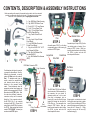
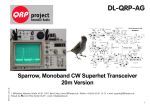
RAM
OWNERS MANUAL
Mounting Systems
PATENTED & PATENTS PENDING
RAM
POWERED DOCKING CRADLE
PATENTED & PATENTS PENDING
™
For iPAQ Handheld Computers
Charging/Serial Dock for iPAQ Handhelds
NPI has a Lifetime Warranty on all RAM Mounting Systems
and a Limited Warranty on all electronic components.
Detailed information regarding these warranties may be
accessed on our web site at www.ram-mount.com
NPI
National Products Inc.
Tel: (206) 763-8361 Fax: (206) 763-9615
Web Site: http://www.ram-mount.com
e-mail: [email protected]
(For iPAQ 3100, 3600, 3700, 3800, 3900, 5400 & 5500 Series)
Provides constant charging and power for iPAQ electronic device in 12
to 28 Volt DC environments. Supplied wire harnesses allow for null or
non-null modem cables. Includes fused coiled power cord with cigarette
lighter plug and straight type power cord for hard wire applications (add
to 2 Amp fused circuit only). Works with any brand or style expansion
pack, plus the HP keyboard and all Navman GPS sleeves.
PLEASE SEE IMPORTANT INSTRUCTIONS
INSIDE BEFORE MOUNTING YOUR IPAQ !
RPR-182-CO2-INS
CONTENTS, DESCRIPTION & ASSEMBLY INSTRUCTIONS
Before proceeding with assembly of powered docking cradle, check the contents of
package to make certain all parts are included. If any parts are missing, please
contact NPI for a replacement part at: [email protected]
A. 1 qty. RAM Main Plastic Housing
B. 1 qty. RAM PCB Plastic Cover
C. 2 qty. #8 X 1 1/4” Long Screws
D. 1 qty. 10’ Long Power Cord
E. 1 qty. 10’ Long Coiled Power
Cord With Cigarette Plug
F. 1 qty. Power Printed Circuit
Board
G. 1 qty. Input / Output Printed
Circuit Board
H. 1 qty. IPAQ Male Connector
Printed Circuit Board
J. 2 qty. of ea. #8-32 X 5/8” & 1/2”
Long Screws & #8 Nuts
K. 1 qty. Non-Null Modem Wire
Harness (BLACK)
L. 1 qty. Null Modem Wire Harness
(RED)
D
A
E
F
J
G
K
H
L
B
C
Locating
Pins
STEP 2
Assemble power PCB (F) on the three
corresponding pins on the housing (A)
as shown in STEP 2 photo.
Large Side
Small Side
Wire Path
IPAQ Male Connector PCB
11 qty. Connector
First determine what type of connection
you require for the serial port. We offer 2
different wire harnesses, a non-nullmodem (K Black) and null modem (L
Red). To determine what type you
require, contact the manufacturer of
your electronic device that you are
attaching to the powered docking
cradle. Once determined, select the
appropriate colored wire harness and
attach it to the corresponding PCB’s G &
H as shown in the STEP 1 photo. Note,
the ends have different numbers of
connectors so they can’t be reversed.
Attach the 10 qty. connector socket to
the G PCB & the 11 qty. connector
housing to the H PCB. Connect the 3
wire socket on the G PCB to the pins on
the F PCB. Make certain that the label
marked “TOP FACING” is toward you
as shown in the STEP 1 photo.
Slotted Posts
STEP 3
Assemble Input / Output PCB (G) to the
two slotted posts on housing (A) as
shown in STEP 3 photo. Note: prebend the wire harness to aid in holding
the PCB’s in place and note the
direction path of the wires.
No Wires
This Area
H
K
Black
non-null
modem
F
Power
PCB
G
L
Input / Output
Red
PCB
null modem
10 qty. Connector
STEP 1
STEP 4
The iPAQ Male PCB (H) has 2 different
sized connectors. Before assembly, try
the connector into your device to
determine which one is to be used.
Once that is determined, look on
housing (A) to see the Small & Large
lettering to indicate the side that the
PCB will be on. Then assemble it as
shown in STEP 4 photo. Note: prebend the wire harness to aid in holding
the PCB’s in place and note the
direction path of the wires.
STEP 5
Using a pointer, or similar device, insert
it through the serial port hole in plastic
cover (B) to aid in holding the PCB’s in
place while aligning and attaching the
cover with the 2 screws (C). Gently
snug the screws until the cover (B)
touches housing (A).