1
Para obtener un ejemplar en Español de este
Manual del propietario, visite www.heatnglo.com.
Pour demander un exemplaire en français de ce Manuel
du propriétaire, visitez www.heatnglo.com.
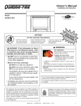
Owner’s Manual
R
Installation and Operation
Model:
Expression 36 (QV36A-FB)
CAUTION
DO NOT DISCARD THIS MANUAL
• Important operating
and maintenance
instructions included.
• Read, understand and follow
these instructions for safe
installation and operation.
WARNING: If the information in these
instructions is not followed exactly, a fire
or explosion may result causing property
damage, personal injury, or death.
• Do not store or use gasoline or other flammable vapors and liquids in the vicinity of
this or any other appliance.
• What to do if you smell gas
- Do not try to light any appliance.
- Do not touch any electrical switch. Do not
use any phone in your building.
- Immediately call your gas supplier from a
neighbor’s phone. Follow the gas supplier’s instructions.
- If you cannot reach your gas supplier, call
the fire department.
• Installation and service must be performed
by a qualified installer, service agency, or the
gas supplier.
This appliance may be installed as an OEM installation in
manufactured home (USA only) or mobile home and must be
installed in accordance with the manufacturer’s instructions and
the manufactured home construction and safety standard, Title
24 CFR, Part 3280 or Standard for Installation in Mobile Homes,
CAN/CSA Z240MH.
This appliance is only for use with the type(s) of gas indicated
on the rating plate.
• Leave this manual with
party responsible for use
and operation.
D
DI O N
SC OT
AR
D
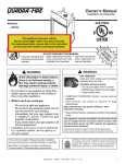
WARNING
HOT SURFACES!
Glass and other surfaces are hot during
operation AND cool down.
Hot glass will cause burns.
• DO NOT touch glass until it is cooled
• NEVER allow children to touch glass
• Keep children away
• CAREFULLY SUPERVISE children in same room as
fireplace.
• Alert children and adults to hazards of high temperatures.
High temperatures may ignite clothing or other flammable
materials.
• Keep clothing, furniture, draperies and other flammable
materials away.
This appliance has been supplied with an integral barrier
to prevent direct contact with the fixed glass panel. DO
NOT operate the appliance with the barrier removed.
Contact your dealer or Hearth & Home Technologies if the
barrier is not present or help is needed to properly install one.
In the Commonwealth of Massachusetts:
• installation must be performed by a licensed plumber
or gas fitter;
See Table of Contents for location of additional
Commonwealth of Massachusetts requirements.
Installation and service of this appliance should be
performed by qualified personnel. Hearth & Home
Technologies suggests NFI certified or factory trained
professionals, or technicians supervised by an NFI
certified professional.
Quadra-Fire • Expression 36 (QV36A-FB) • 2062-900 Rev. S • 11/11
1
Read this manual before installing or operating this appliance.
Please retain this owner’s manual for future reference.
Congratulations
Congratulations on selecting a Quadra-Fire gas appliance
—an elegant and clean alternative to wood burning
appliances. The Quadra-Fire gas appliance you have
selected is designed to provide the utmost in safety,
reliability, and efficiency.
This Owner’s Manual should be retained for future
reference. We suggest that you keep it with your other
important documents and product manuals.
The information contained in this Owner’s Manual, unless
Noted otherwise, applies to all models and gas control
systems.
As the owner of a new appliance, you’ll want to read and
carefully follow all of the instructions contained in this
Owner’s Manual. Pay special attention to all Cautions and
Warnings.
Your new Quadra-Fire gas appliance will give you years of
durable use and trouble-free enjoyment. Welcome to the
Quadra-Fire family of appliance products!
We recommend that you record the following pertinent
information about your appliance.
Homeowner Reference Information
Model Name: ___________________________________________ Date purchased/installed: __________________
Serial Number:__________________________________________ Location on appliance: ____________________
Dealership purchased from: _______________________________ Dealer Phone: __________________________
Notes: _______________________________________________________________________________________
_____________________________________________________________________________________________
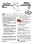
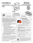
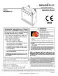
Listing Label Information/Location
The model information regarding your specific appliance can be found on
the rating plate usually located in the control area of the appliance.
R
Quadra-Fire, a brand of Hearth & Home Technologies, Inc.
7571 215th Street West, Lakeville, MN 55044
Type of Gas
Not for use with solid fuel.
(Ne doit pas entre utilise avec un combustible solide).
Type of Gas (Sorte De Gaz):
NATURAL GAS
Gas and Electric
Information
This appliance must be installed in accordance with local codes, if any; if not, follow ANSI Z223.1
in the USA or CAN/CGA B149 installation codes. (Installer l’appareil selon les codes ou reglements
locaux ou, en l’absence de tels reglements, selon les codes d’installation
ANSI Z21XX-XXXX · CSA 2.XX-MXX · UL307B
Minimum Permissible Gas Supply for Purposes of Input Adjustment.
Approved Minimum (De Gaz) Acceptable
0.0 in w.c.
(Po. Col. d’eau)
Maximum Pressure (Pression)
0.0 in w.c.
(Po. Col. d’eau)
Maximum Manifold Pressure (Pression)
0.0 in w.c.
(Po. Col. d’eau)
Minimum Manifold Pressure (Pression)
0.0 in w.c.
(Po. Col. d’eau)
Total Electrical Requirements: 000Vac, 00Hz., less than 00 Amperes
ALTITUDE:
MAX. INPUT BTUH:
MIN. INPUT BTUH:
ORIFICE SIZE:
2
0-0000 FT.
00,000
00,000
#XXXXX
IN CANADA
0000-0000FT.
00,000
00,000
#XXXXX
Model Number
MADE IN USA
Model:
(Modele):
XXXXXXXX
Serial
(Serie):
XXXXXXXX
Quadra-Fire • Expression 36 (QV36A-FB) • 2062-900 Rev. S • 11/11
Serial Number
Table of Contents
1 Listing and Code Approvals
A.
B.
C.
D.
E.
F.
G.
9 Gas Information
Appliance Certification . . . . . . . . . . . . . . . . . . . . . . . . . . . .
BTU Specifications . . . . . . . . . . . . . . . . . . . . . . . . . . . . . . .
High Altitude Installations . . . . . . . . . . . . . . . . . . . . . . . . . .
Non-Combustible Materials Specification. . . . . . . . . . . . . .
Combustible Materials Specification . . . . . . . . . . . . . . . . .
Electrical Codes . . . . . . . . . . . . . . . . . . . . . . . . . . . . . . . . .
Requirements for the Commonwealth of Massachusetts . .
4
4
4
4
4
4
5
2 Getting Started
A.
B.
C.
D.
Design and Installation Considerations . . . . . . . . . . . . . . .
Tools and Supplies Needed . . . . . . . . . . . . . . . . . . . . . . . .
Inspect Appliance and Components . . . . . . . . . . . . . . . . . .
Inspect Firebox . . . . . . . . . . . . . . . . . . . . . . . . . . . . . . . . . .
6
6
6
7
Selecting Appliance Location . . . . . . . . . . . . . . . . . . . . . . .
Constructing the Appliance Chase . . . . . . . . . . . . . . . . . . .
Mantel Projections . . . . . . . . . . . . . . . . . . . . . . . . . . . . . . .
Clearances . . . . . . . . . . . . . . . . . . . . . . . . . . . . . . . . . . . . .
8
9
9
9
4 Termination Locations
A. Vent Termination Minimum Clearances . . . . . . . . . . . . . . .11
5 Vent Information and Diagrams
A.
B.
C.
D.
10 Electrical Information
A.
B.
C.
D.
E.
F.
Recommendation for Wire . . . . . . . . . . . . . . . . . . . . . . . .
Connecting to the Appliance. . . . . . . . . . . . . . . . . . . . . . .
IntelliFire Ignition System Wiring . . . . . . . . . . . . . . . . . . .
Optional Accessories Requirements . . . . . . . . . . . . . . . .
QWSK-MLT Wall Switch Kit . . . . . . . . . . . . . . . . . . . . . . .
Junction Box Installation. . . . . . . . . . . . . . . . . . . . . . . . . .
31
31
31
32
32
35
11 Finishing
A. Mantel Projections . . . . . . . . . . . . . . . . . . . . . . . . . . . . . . 36
B. Facing Material . . . . . . . . . . . . . . . . . . . . . . . . . . . . . . . . . 36
3 Framing and Clearances
A.
B.
C.
D.
A. Fuel Conversions . . . . . . . . . . . . . . . . . . . . . . . . . . . . . . . 29
B. Gas Pressures . . . . . . . . . . . . . . . . . . . . . . . . . . . . . . . . . 29
C. Gas Connection . . . . . . . . . . . . . . . . . . . . . . . . . . . . . . . . 29
Vent Table Key . . . . . . . . . . . . . . . . . . . . . . . . . . . . . . . . .
Use of Elbows . . . . . . . . . . . . . . . . . . . . . . . . . . . . . . . . .
Measuring Standards . . . . . . . . . . . . . . . . . . . . . . . . . . . .
Vent Diagrams . . . . . . . . . . . . . . . . . . . . . . . . . . . . . . . . .
13
13
13
14
6 Vent Clearances and Framing
A. Pipe Clearances to Combustibles . . . . . . . . . . . . . . . . . . 18
B. Wall Penetration Framing . . . . . . . . . . . . . . . . . . . . . . . . . 18
C. Vertical Penetration Framing . . . . . . . . . . . . . . . . . . . . . . 19
12 Appliance Setup
A.
B.
C.
D.
E.
F.
G.
H.
I.
Remove Shipping Materials . . . . . . . . . . . . . . . . . . . . . . .
Clean the Appliance . . . . . . . . . . . . . . . . . . . . . . . . . . . . .
Accessories . . . . . . . . . . . . . . . . . . . . . . . . . . . . . . . . . . .
Ember Placement . . . . . . . . . . . . . . . . . . . . . . . . . . . . . . .
Positioning the Logs . . . . . . . . . . . . . . . . . . . . . . . . . . . . .
Glass Assembly . . . . . . . . . . . . . . . . . . . . . . . . . . . . . . . .
Burner Removal (Only for Servicing) . . . . . . . . . . . . . . . .
Grilles and Trim . . . . . . . . . . . . . . . . . . . . . . . . . . . . . . . .
Air Shutter Setting . . . . . . . . . . . . . . . . . . . . . . . . . . . . . .
37
37
37
37
38
41
41
42
42
13 Operating Instructions
A.
B.
C.
D.
Before Lighting Appliance. . . . . . . . . . . . . . . . . . . . . . . . .
Lighting Appliance . . . . . . . . . . . . . . . . . . . . . . . . . . . . . .
After Appliance is Lit . . . . . . . . . . . . . . . . . . . . . . . . . . . . .
Frequently Asked Questions . . . . . . . . . . . . . . . . . . . . . .
43
44
45
45
14 Troubleshooting
A. IntelliFire Ignition System . . . . . . . . . . . . . . . . . . . . . . . . . 46
7 Appliance Preparation
A.
B.
C.
D.
Removing Non-combustible Facing Material Assembly . .
Installing the Optional Heat-Zone® Gas Kit . . . . . . . . . . .
Securing and Leveling the Appliance . . . . . . . . . . . . . . . .
Installing Non-combustible Facing Material . . . . . . . . . . .
20
20
21
22
8 Installing Vent Pipe
A.
B.
C.
D.
Assembly of Vent Sections . . . . . . . . . . . . . . . . . . . . . . . .
Disassembly of Vent Sections . . . . . . . . . . . . . . . . . . . . .
Installing Heat Shield and Horizontal Termination Cap . .
Installing Roof Flashing and Vertical Termination Cap . . .
23
25
26
27
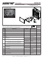
15 Maintaining and Servicing Appliance
A. Maintenance Tasks. . . . . . . . . . . . . . . . . . . . . . . . . . . . . . 49
16 Reference Materials
A.
B.
C.
D.
E.
Appliance Dimension Diagram . . . . . . . . . . . . . . . . . . . . .
Vent Components Diagrams . . . . . . . . . . . . . . . . . . . . . .
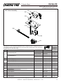
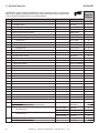
Service Parts List . . . . . . . . . . . . . . . . . . . . . . . . . . . . . .
Limited Lifetime Warranty . . . . . . . . . . . . . . . . . . . . . . . . .
Contact Information . . . . . . . . . . . . . . . . . . . . . . . . . . . . .
50
51
56
57
59
= Contains updated information.
Quadra-Fire • Expression 36 (QV36A-FB) • 2062-900 Rev. S • 11/11
3
1
Listing and Code Approvals
A. Appliance Certification
C. High Altitude Installations
MODELS: QV36A-FB
LABORATORY: Underwriters Laboratories, Inc. (UL)
TYPE: Direct Vent Gas Appliance Heater
STANDARD: ANSI Z21.88-2002 • CSA2.33-M02 • UL307B
This product is listed to ANSI standards for “Vented Gas
Appliance Heaters” and applicable sections of “Gas Burning Heating Appliances for Manufactured Homes and
Recreational Vehicles”, and “Gas Fired Appliances for
Use at High Altitudes”.
NOT INTENDED FOR USE AS A PRIMARY HEAT SOURCE.
This appliance is tested and approved as either supplemental room heat or as a decorative appliance. It should not be
factored as primary heat in residential heating calculations.
Note: This installation must conform with local codes. In the
absence of local codes you must comply with the National
Fuel Gas Code, ANSI Z223.1-latest edition in the U.S.A. and
the CAN/CGA B149 Installation Codes in Canada.
U.L. Listed gas appliances are tested and approved without requiring changes for elevations from 0 to 2000 feet in
the U.S.A. and Canada.
When installing this appliance at an elevation above 2000
feet, it may be necessary to decrease the input rating
by changing the existing burner orifice to a smaller size.
Input rate should be reduced by 4% for each 1000 feet
above a 2000 foot elevation in the U.S.A., or 10% for elevations between 2000 and 4500 feet in Canada. If the
heating value of the gas has been reduced, these rules
do not apply. To identify the proper orifice size, check with
the local gas utility.
If installing this appliance at an elevation above 4500 feet
(in Canada), check with local authorities.
WARNING
Do NOT use this appliance if any part has been under water.
Immediately call a qualified service technician to inspect the
appliance and to replace any part of the control system and
any gas control which has been under water.
D. Non-Combustible Materials Specification
Material which will not ignite and burn. Such materials are
those consisting entirely of steel, iron, brick, tile, concrete,
slate, glass or plasters, or any combination thereof.
B. BTU Specifications
Expression 36
(QV36A-FB)
(NG)
(LP)
Maximum
Input
BTUH
Minimum
Input
BTUH
Orifice
Size
(DMS)
US
(0-2000 FT)
37,000
24,000
32
CANADA
(2000-4500 FT)
33,300
21,600
33
US
(0-2000 FT)
36,000
26,000
50
(2000-4500 FT)
32,400
23,400
51
Materials that are reported as passing ASTM E 136,
Standard Test Method for Behavior of Materials in a
Vertical Tube Furnace at 750ºC, shall be considered
non-combustible materials.
E. Combustible Materials Specification
Materials made of or surfaced with wood, compressed
paper, plant fibers, plastics, or other material that can ignite and burn, whether flame proofed or not, or whether
plastered or unplastered shall be considered combustible
materials.
F. Electrical Codes
NOTICE: This appliance must be electrically wired and
grounded in accordance with local codes or, in the absence
of local codes, with National Electric Code ANSI/NFPA
70-latest edition or the Canadian Electric Code CSA
C22.1.
• A 110-120 VAC circuit for this product must be protected
with ground-fault circuit-interrupter protection, in compliance
with the applicable electrical codes, when it is installed in
locations such as in bathrooms or near sinks.
4
Quadra-Fire • Expression 36 (QV36A-FB) • 2062-900 Rev. S • 11/11
Note: The following requirements reference various
Massachusetts and national codes not contained in this
document.
G. Requirements for the Commonwealth of
Massachusetts
For all side wall horizontally vented gas fueled equipment
installed in every dwelling, building or structure used in
whole or in part for residential purposes, including those
owned or operated by the Commonwealth and where the
side wall exhaust vent termination is less than seven (7)
feet above finished grade in the area of the venting, including but not limited to decks and porches, the following
requirements shall be satisfied:
Installation of Carbon Monoxide Detectors
At the time of installation of the side wall horizontal vented
gas fueled equipment, the installing plumber or gas fitter
shall observe that a hard wired carbon monoxide detector
with an alarm and battery back-up is installed on the floor
level where the gas equipment is to be installed. In addition, the installing plumber or gas fitter shall observe that
a battery operated or hard wired carbon monoxide detector with an alarm is installed on each additional level of
the dwelling, building or structure served by the side wall
horizontal vented gas fueled equipment. It shall be the
responsibility of the property owner to secure the services
of qualified licensed professionals for the installation of
hard wired carbon monoxide detectors.
In the event that the side wall horizontally vented gas fueled equipment is installed in a crawl space or an attic,
the hard wired carbon monoxide detector with alarm and
battery back-up may be installed on the next adjacent
floor level.
In the event that the requirements of this subdivision can
not be met at the time of completion of installation, the
owner shall have a period of thirty (30) days to comply
with the above requirements; provided, however, that during said thirty (30) day period, a battery operated carbon
monoxide detector with an alarm shall be installed.
Approved Carbon Monoxide Detectors
Each carbon monoxide detector as required in accordance with the above provisions shall comply with NFPA
720 and be ANSI/UL 2034 listed and IAS certified.
Signage
A metal or plastic identification plate shall be permanently mounted to the exterior of the building at a minimum
height of eight (8) feet above grade directly in line with the
exhaust vent terminal for the horizontally vented gas fueled heating appliance or equipment. The sign shall read,
in print size no less than one-half (1/2) inch in size, “GAS
VENT DIRECTLY BELOW. KEEP CLEAR OF ALL OBSTRUCTIONS”.
Inspection
The state or local gas inspector of the side wall horizontally vented gas fueled equipment shall not approve the
installation unless, upon inspection, the inspector observes carbon monoxide detectors and signage installed
in accordance with the provisions of 248 CMR 5.08(2)(a)1
through 4.
Exemptions
The following equipment is exempt from 248 CMR
5.08(2)(a)1 through 4:
• The equipment listed in Chapter 10 entitled “Equipment Not Required To Be Vented” in the most current
edition of NFPA 54 as adopted by the Board; and
• Product Approved side wall horizontally vented gas fueled equipment installed in a room or structure separate from the dwelling, building or structure used in
whole or in part for residential purposes.
MANUFACTURER REQUIREMENTS
Gas Equipment Venting System Provided
When the manufacturer of Product Approved side wall
horizontally vented gas equipment provides a venting
system design or venting system components with the
equipment, the instructions provided by the manufacturer
for installation of the equipment and the venting system
shall include:
• Detailed instructions for the installation of the venting
system design or the venting system components; and
• A complete parts list for the venting system design or
venting system.
Gas Equipment Venting System NOT Provided
When the manufacturer of a Product Approved side wall
horizontally vented gas fueled equipment does not provide the parts for venting the flue gases, but identifies
“special venting systems”, the following requirements
shall be satisfied by the manufacturer:
• The referenced “special venting system” instructions
shall be included with the appliance or equipment installation instructions; and
• The “special venting systems” shall be Product Approved by the Board, and the instructions for that system shall include a parts list and detailed installation
instructions.
A copy of all installation instructions for all Product Approved side wall horizontally vented gas fueled equipment, all venting instructions, all parts lists for venting
instructions, and/or all venting design instructions shall
remain with the appliance or equipment at the completion
of the installation.
See Gas Connection section for additional Commonwealth of Massachusetts requirements.
Quadra-Fire • Expression 36 (QV36A-FB) • 2062-900 Rev. S • 11/11
5
2
Getting Started
A. Design and Installation Considerations
Quadra-Fire direct vent gas appliances are designed to
operate with all combustion air siphoned from outside of
the building and all exhaust gases expelled to the outside.
No additional outside air source is required.
CAUTION
Check building codes prior to installation.
• Installation MUST comply with local, regional, state and
national codes and regulations.
• Consult local building, fire officials or authorities having jurisdiction about restrictions, installation inspection, and permits.
When planning an appliance installation, it’s necessary to
determine the following information before installing:
• Where the appliance is to be installed.
• The vent system configuration to be used.
• Gas supply piping.
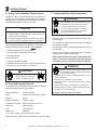
C. Inspect Appliance and Components
WARNING
Inspect appliance and components for damage.
Damaged parts may impair safe operation.
• Do NOT install damaged components.
• Do NOT install incomplete components.
• Do NOT install substitute components.
Report damaged parts to dealer.
• Carefully remove the appliance and components from
the packaging.
• The vent system components and trim doors are shipped
in separate packages.
• The gas logs may be packaged separately and must be
field installed.
• Report to your dealer any parts damaged in shipment,
particularly the condition of the glass.
• Read all of the instructions before starting the installation. Follow these instructions carefully during the
installation to ensure maximum safety and benefit.
• Electrical wiring.
• Framing and finishing details.
• Whether optional accessories—devices such as a fan,
wall switch, or remote control—are desired.
WARNING
Keep appliance dry.
• Mold or rust may cause odors.
• Water may damage controls.
B. Tools and Supplies Needed
Before beginning the installation be sure that the following
tools and building supplies are available.
Reciprocating saw
Framing material
Pliers
Noncorrosive leak check solution
Hammer
Gloves
Phillips screwdriver
Framing square
Flat blade screwdriver
Electric drill and bits (1/4 in.)
Plumb line
Safety glasses
Level
Tape measure
Manometer
Voltmeter
WARNING
Hearth & Home Technologies disclaims any
responsibility for, and the warranty will be voided
by, the following actions:
• Installation and use of any damaged appliance or vent
system component.
• Modification of the appliance or vent system.
• Installation other than as instructed by Hearth & Home
Technologies.
• Improper positioning of the gas logs or the glass door.
• Installation and/or use of any component part not approved
by Hearth & Home Technologies.
Any such action may cause a fire hazard.
1/2 - 3/4 inch length, #6 or #8 Self-drilling screws
Caulking material (300ºF minimum continuous exposure rating)
6
Quadra-Fire • Expression 36 (QV36A-FB) • 2062-900 Rev. S • 11/11
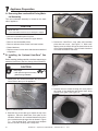
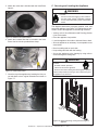
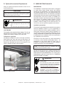
D. Inspect Firebox
Surface cracking or crazing of firebrick material is normal
and expected. The following types of cracks are acceptable
and do not require replacement of the unit or the firebox:
• Cracks that do not propagate entirely through the
material.
• Light fracture lines or “spider-webbing” on the surface of
the material.
• Cracks that are less than 1/32 in. wide and less than 3
in. long.
• If cosmetically unacceptable, such cracks may be
repaired with the SRV-PACK service kit. See Service
Parts List.
Cracks that are unacceptable:
• Cracks greater than 1/32 in. wide and 3 in. long are at
risk of growing.
• Cracks that penetrate entirely through the firebrick
material.
Inspection for cracking should be run when the appliance
is cool. Cracks tend to close as the appliance heats up.
Quadra-Fire • Expression 36 (QV36A-FB) • 2062-900 Rev. S • 11/11
7
3
Framing and Clearances
WARNING
Note:
• Illustrations reflect typical installations and are FOR
DESIGN PURPOSES ONLY.
• Illustrations/diagrams are not drawn to scale.
• Actual installation may vary due to individual design
preference.
Fire Risk
Provide adequate clearance:
• Around air openings
• To combustibles
• For service access
Locate appliance away from traffic areas.
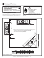
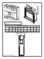
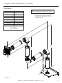
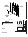
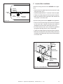
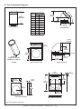
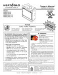
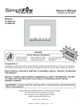
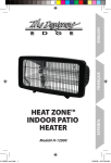
A. Selecting Appliance Location
When selecting a location for your appliance it is important to
consider the required clearances to walls (see figure 3.1).
Note: For actual appliance dimensions refer to Section 16.
F
B
A
In addition to these framing dimensions, also reference the following sections:
• Clearances and Mantel Projections (Sections 3.C and 3.D)
• Vent Clearances and Framing (Section 6).
F
E
D
C
1/2 in.
Model
A
B
Inches
41-1/2 17-1/4
Expression 36
(QV36A-FB) Millimeters 1054
439
C
D
E
F
32
45-1/4
64
12
813
1150
1626
305
Figure 3.1 Appliance Locations
8
Quadra-Fire • Expression 36 (QV36A-FB) • 2062-900 Rev. S • 11/11
B. Constructing the Appliance Chase
D. Clearances
A chase is a vertical boxlike structure built to enclose the
gas appliance and/or its vent system. Vertical vents that
run on the outside of a building may be, but are not required to be, installed inside a chase.
Construction of the chase may vary with the type of building. These instructions are not substitutes for the requirements of local building codes. Local building codes MUST
be checked.
Chases should be constructed in the manner of all outside walls of the home to prevent cold air drafting problems. The chase should not break the outside building
envelope in any manner.
Walls, ceiling, base plate and cantilever floor of the chase
should be insulated. Vapor and air infiltration barriers
should be installed in the chase as per regional codes for
the rest of the home. Additionally, in regions where cold
air infiltration may be an issue, the inside surfaces may be
sheetrocked and taped for maximum air tightness.
WARNING
Fire Risk.
Odor Risk.
• Install appliance on hard metal or wood surfaces
extending full width and depth of appliance.
• Do NOT install appliance directly on carpeting,
vinyl, tile or any combustible material other than
wood.
WARNING
Fire Risk.
• Construct chase to all clearance specifications
in manual.
• Locate and install appliance to all clearance
specifications in manual.
To further prevent drafts, the wall shield and ceiling
firestops should be caulked with caulk with a minimum
of 300ºF continuous exposure rating to seal gaps. Gas line
holes and other openings should be caulked with caulk
with a minimum of 300ºF continuous exposure rating or
stuffed with unfaced insulation. If the appliance is being
installed on a cement surface, a layer of plywood may be
placed underneath to prevent conducting cold up into the
room.
5
4
3
2
1
1
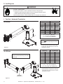
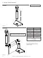
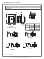
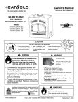
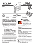
C. Mantel Projections
1/2
2
4
6
Note: Dimensions
shown in inches.
8
3 IN. MIN.
Figure 3.3 Clearances to Mantel Legs or Wall Projections
(Acceptable on both sides of opening.)
12 IN. MAX.
23 IN.
1 IN. MAX.
14 IN.
18 IN. MIN.
12 IN. MIN.
Figure 3.2 Clearances to Mantels or Other Combustibles
Above Appliance
Quadra-Fire • Expression 36 (QV36A-FB) • 2062-900 Rev. S • 11/11
9
A
E
J
B
F
C
H
D
G
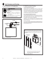
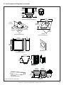
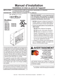
Note: Framing should be constructed of 2 X 4 lumber
or heavier. The framing headers may rest on the appliance stand-offs.
I
Clearance to Combustibles
A
B
C
D
E
F
G
H
I
J
Rough
Opening
(Vent Pipe)
Rough
Opening
(Height)
Rough
Opening
(Depth)
Rough
Opening
(Width)
Clearance
to Ceiling
Combustible
Floor
Combustible
Flooring
Behind
Appliance
Sides of
Appliance
Front of
Appliance
Inches
10
52
17-1/4
41-1/2
32-1/2
0
0
1
1/2
36
Millimeters
254
1321
438
1054
825
0
0
25
13
914
NON-COMBUSTIBLE ZONE IS DEFINED BY 3 INCHES
ABOVE THE ELBOW FOR THE ENTIRE WIDTH AND
DEPTH (BEHIND THE FRONT HEADER) OF THE FIREBOX.
WALL STUD
3 IN.
Figure 3.4 Clearances to Combustibles
10
Quadra-Fire • Expression 36 (QV36A-FB) • 2062-900 Rev. S • 11/11
4
Termination Locations
A. Vent Termination Minimum Clearances
HORIZONTAL
OVERHANG
2 FT.
MIN.
WARNING
Fire Risk.
Explosion Risk.
Inspect external vent cap regularly.
• Ensure no debris blocks cap.
• Combustible materials blocking cap may
ignite.
• Restricted air flow affects burner operation.
WARNING
Fire Risk.
Explosion Risk.
Maintain vent clearance to combustibles as
specified.
• Do not pack air space with insulation or other
materials.
Failure to keep insulation or other materials
away from vent pipe may cause fire.
Measure vertical clearances from this surface.
20 INCHES MIN.
VERTICAL
WALL
LOWEST
DISCHARGE
OPENING
GAS DIRECT VENT
TERMINATION CAP
X
12
ROOF PITCH
IS X/ 12
H (MIN.) - MINIMUM HEIGHT FROM ROOF
TO LOWEST DISCHARGE OPENING
Roof Pitch
H (Min.) Ft.
Flat to 6/12...........................................................1.0*
Over 6/12 to 7/12 .................................................1.25*
Over 7/12 to 8/12 .................................................1.5*
Over 8/12 to 9/12 .................................................2.0*
Over 9/12 to 10/12 ...............................................2.5
Over 10/12 to 11/12 .............................................3.25
Over 11/12 to 12/12 .............................................4.0
Over 12/12 to 14/12 .............................................5.0
Over 14/12 to 16/12 .............................................6.0
Over 16/12 to 18/12 .............................................7.0
Over 18/12 to 20/12 .............................................7.5
Over 20/12 to 21/12 .............................................8.0
* 3 foot minimum in snow regions
Figure 4.2 Minimum height from roof to lowest discharge
opening
Figure 4.2 specifies minimum vent heights for various
pitched roofs.
A
B
6 in. (minimum) up to 20 in.
152 mm/508 mm
18 in. minimum
457 mm
20 in. and over
0 in. minimum
Gas, Wood or Fuel Oil
Termination Cap
B
A*
Measure horizontal clearances from this surface.
Gas
Termination
Cap **
(See Figure 4.4 for specific clearances)
Figure 4.1
*
**
If using decorative cap cover(s), this distance may need to be
increased. Refer to the installation instructions supplied with the
decorative cap cover.
In a staggered installation with both gas and wood or fuel oil
terminations, the wood or fuel oil termination cap must be
higher than the gas termination cap.
Figure 4.3 Multiple Vertical Termination
Quadra-Fire • Expression 36 (QV36A-FB) • 2062-900 Rev. S • 11/11
11
O
N
P
R
F
C
V
Q
B
J
H or I
B
V
D
B
V
V
V
H
V
X
G
M
V
A
V
E
H
V
V
V
L
A
V
V = VENT TERMINAL
X = AIR SUPPLY INLET
K
B
C
= 6 inches...................clearance to outside corner
E
= 6 inches...................clearance to inside corner
Covered Alcove Applications
(Spaces open only on one side and with an overhang)
N
= 6 inches ........... non-vinyl sidewalls
12 inches ......... vinyl sidewalls
O
= 18 inches ......... non-vinyl soffit and overhang
42 inches ......... vinyl soffit and overhang
P
F
= 3 ft. (Canada) ..........not to be installed above a gas meter/regulator assembly within 3 feet
horizontally from the center-line of the
regulator
G = 3 ft ...........................clearance to gas service regulator
vent outlet
H
= 12 inches.................clearance to non-mechanical (unpowered) air supply inlet, combustion air
inlet or direct-vent termination
i
= 3 ft. (U.S.A.)
6 ft. (Canada) ...........clearance to a mechanical (powered)
air supply inlet
All mechanical air intakes within 10 feet of a termination cap
must be a minimum of 3 feet below termination.
J
= 7 ft. ......................... On public property: clearance above
paved sidewalk or a paved driveway.
A vent shall not terminate directly above a sidewalk or paved
driveway which is located between two single family dwellings
and serves both dwellings.
= 8 ft.
QMIN
RMAX
1 cap
3 feet
2 x Q ACTUAL
2 caps
6 feet
1 x Q ACTUAL
3 caps
9 feet
2/3 x Q ACTUAL
4 caps
12 feet
1/2 x Q ACTUAL
QMIN = # termination caps x 3
RMAX = (2 / # termination caps) x QACTUAL
Measure vertical clearances from this surface.
Measure horizontal clearances from this surface.
K
= 6 inches.................clearance from sides of electrical
service
CAUTION! Risk of Burns! Termination caps are HOT,
consider proximity to doors, traffic areas or where people
may pass or gather (sidewalk, deck, patio, etc.). Listed cap
shields available. Contact your dealer.
L
= 12 inches................clearance above electrical service
•
Local codes or regulations may require different
clearances.
•
Vent system termination is NOT permitted in screened
porches.
•
Vent system termination is permitted in porch areas with
two or more sides open.
•
Hearth & Home Technologies assumes no responsibility
for the improper performance of the appliance when the
venting system does not meet these requirements.
Vinyl protection kits are suggested for use with vinyl siding.
Location of the vent termination must not interfere with access to the
electrical service.
M
= 18 inches ....................clearance under veranda, porch, deck,
balcony or overhang
42 inches ................vinyl or composite overhang
Permitted when veranda, porch, deck or balcony is fully open
on a minimum of 2 sides beneath the floor.
Figure 4.4 Minimum Clearances for Termination
12
V
V
= 12 inches.................clearances above grade, veranda,
porch, deck or balcony
= 12 inches.................clearance to window or door that may
be opened, or to permanently closed
window
= 18 inches.................clearance below unventilated soffit
18 inches.................clearance below ventilated soffit
30 inches ................clearance below vinyl soffits and
electrical service
D
K
C
= AREA WHERE TERMINAL IS NOT PERMITTED
A
Electrical
Service
•
Quadra-Fire • Expression 36 (QV36A-FB) • 2062-900 Rev. S • 11/11
5
Vent Information and Diagrams
A. Vent Table Key
The abbreviations listed in this vent table key are used in
the vent diagrams.
First section (closest to appliance) of vertical length
V2
Second section of vertical length
H1
First section (closest to appliance) of horizontal length
H2
Second section of horizontal length
Vertical
12
V1
8-1/2 in.
WARNING
Fire Hazard.
Explosion Risk.
Asphyxiation Risk.
Do NOT connect this gas appliance to a chimney
flue serving a separate solid-fuel or gas burning
appliance.
• Vent this appliance directly outside.
• Use separate vent system for this appliance.
May impair safe operation of this appliance or
other appliances connected to the flue.
8-1/2 in.
Description
in
.
Symbol
Horizontal
Figure 5.1
C. Measuring Standards
Vertical and horizontal measurements listed in the vent
diagrams were made using the following standards.
1. Pipe measurements are shown using the effective length
of pipe (see Figure 5.2).
2. Measurements are made from the appliance outer wrap,
not from the standoffs.
B. Use of Elbows
CAUTION
ALL vent configuration specifications MUST be followed.
• This product is tested and listed to these specifications.
• Appliance performance will suffer if specifications are not
followed.
Diagonal runs have both vertical and horizontal vent aspects when calculating the effects. Use the rise for the
vertical aspect and the run for the horizontal aspect (see
Figure 5.1).
3. Horizontal terminations are measured to the outside
mounting surface (flange of termination cap) (see
Figure 4.1).
4. Vertical terminations are measured to bottom of termination cap.
5. Horizontal pipe installed level with no rise.
Pipe
Effective
Height/Length
Two 45º elbows may be used in place of one 90º elbow. On
45º runs, one foot of diagonal is equal to 8-1/2 (216 mm)
inches horizontal run and 8-1/2 (216 mm) inches vertical
run. A length of straight pipe is allowed between two 45º
elbows (see Figure 5.1).
Effective Length
Inches
Millimeters
DVP4
4
102
DVP6
6
152
DVP12
12
305
DVP24
24
610
DVP36
36
914
DVP48
48
1219
DVP6A
3 to 6
76 to 152
DVP12A
3 to 12
76 to 305
DVP12MI 3 to 12
76 to 305
DVP24MI 3 to 24
76 to 610
Figure 5.2 DVP Pipe Effective Length
Quadra-Fire • Expression 36 (QV36A-FB) • 2062-900 Rev. S • 11/11
13
D. Vent Diagrams
WARNING
Fire Risk. Explosion Risk.
Do NOT pack insulation or other combustibles between ceiling firestops.
• ALWAYS maintain specified clearances around venting and firestop systems.
• Install wall shield and ceiling firestops as specified.
Failure to keep insulation or other material away from vent pipe may cause fire.
1. Top Vent - Horizontal Termination
V1 Minimum
One Elbow
V1
H1 Maximum
1 ft.
305 mm
3 ft
924 mm
2-1/2 ft.
762 mm
6 ft
1.8 m
3-1/2 ft.
1.7 m
9 ft
2.7 m
4 ft.
1.2 m
10 ft
3.1 m
4-1/2 ft.
5-1/2 ft.
6-1/2 ft.
7-1/2 ft.
1.4 m
1.7 m
2m
2.3 m
12 ft
15 ft
18 ft
21 ft
3.7 m
4.6 m
5.5 m
6.4 m
H1 = 21 ft. (6.4 m) Maximum
V1 = 40 ft. (12.2 m) Maximum
V1 + H1 = 30 ft. (9.1 m) Maximum*
H1
Note: Must have a 12 inch minimum
vertical vent before attaching a 90° elbow
to the unit.
* If the horizontal component is less than
5 feet then the total vent run can be
extended to 40 feet.
Figure 5.3
V1 Minimum
Two Elbows
Note: Must have a 12 inches minimum
vertical vent before attaching a 90° elbow
to the unit.
H1 + H2 Maximum
1 ft.
305 mm
3 ft
924 mm
2-1/2 ft.
762 mm
6 ft
1.8 m
3-1/2 ft.
1.7 m
9 ft
2.7 m
4 ft.
1.2 m
10 ft
3.1 m
4-1/2 ft.
5-1/2 ft.
6-1/2 ft.
7-1/2 ft.
1.4 m
1.7 m
2m
2.3 m
12 ft
15 ft
18 ft
21 ft
3.7 m
4.6 m
5.5 m
6.4 m
V1 = 40 ft. (12.2 m) Maximum
H1 + H2 = 21 ft. (6.4 m) Maximum
V1 + H1 + H2= 30 ft. (9.1 m) Maximum*
V1
H2
H1
* If the horizontal component is less than
5 feet then the total vent run can be
extended to 40 feet.
INSTALLED
HORIZONTALLY
Figure 5.4
14
Quadra-Fire • Expression 36 (QV36A-FB) • 2062-900 Rev. S • 11/11
1. Top Vent - Horizontal Termination - (continued)
Three Elbows
VT Min.
HT Max.
1 ft. 6 in.
3 ft.
2 ft. 6 in.
6 ft.
3 ft. 6 in.
9 ft.
4 ft.
10 ft.
4 ft. 6 in.
12 ft.
5 ft. 6 in.
15 ft.
6 ft. 6 in.
18 ft.
7 ft. 6 in.
21 ft.
Note: A section of vertical pipe (12 inches minimum)
MUST be installed prior to attaching a 90° elbow.
* If the horizontal component is less than
5 feet then the total vent run can be
extended to 40 feet.
HT = 21 ft. Max
VT = 40 ft. Max
VT + HT = 30 ft. Max*
HT
VT
H2
V2
H1
V1
Figure 5.5
Quadra-Fire • Expression 36 (QV36A-FB) • 2062-900 Rev. S • 11/11
15
2. Top Vent - Vertical Termination
V1 = 40 ft. Max. (12.2 m)
No Elbow
V1
Figure 5.6
Two Elbows
Note: A section of vertical pipe (12 inches minimum)
MUST be installed prior to attaching a 90° elbow.
VT Min.
HT Max.
1 ft. 6 in.
3 ft.
2 ft. 6 in.
6 ft.
3 ft. 6 in.
9 ft.
4 ft.
10 ft.
4 ft. 6 in.
12 ft.
5 ft. 6 in.
15 ft.
6 ft. 6 in.
18 ft.
7 ft. 6 in.
21 ft.
HT = 21 ft. Max
VT = 40 ft. Max
VT + HT = 30 ft. Max*
VT
* If the horizontal component is less than
5 feet then the total vent run can be
extended to 40 feet.
HT
Figure 5.7
16
Quadra-Fire • Expression 36 (QV36A-FB) • 2062-900 Rev. S • 11/11
2. Top Vent - Vertical Termination - (continued)
Three Elbows
Note: A section of vertical pipe (12 inches minimum)
MUST be installed prior to attaching a 90° elbow.
VT Min.
HT Max.
1 ft. 6 in.
3 ft.
2 ft. 6 in.
6 ft.
3 ft. 6 in.
9 ft.
4 ft.
10 ft.
4 ft. 6 in.
12 ft.
5 ft. 6 in.
15 ft.
6 ft. 6 in.
18 ft.
7 ft. 6 in.
21 ft.
HT = 21 ft. Max
VT = 40 ft. Max
VT + HT = 30 ft. Max*
* If the horizontal component is less than
5 feet then the total vent run can be
extended to 40 feet.
V2
VT
HT
H1
H2
V1
INSTALLED
HORIZONTALLY
Figure 5.8
Quadra-Fire • Expression 36 (QV36A-FB) • 2062-900 Rev. S • 11/11
17
6
Vent Clearances and Framing
A. Pipe Clearances to Combustibles
B. Wall Penetration Framing
Combustible Wall Penetration
WARNING
Fire Risk.
Explosion Risk.
Maintain vent clearance to combustibles as
specified.
• Do not pack air space with insulation or
other materials.
Failure to keep insulation or other materials
away from vent pipe may cause fire.
3 in. TOP
CLEARANCE
Frame a hole in a combustible wall for an interior wall
shield firestop, (Figure 6.2) whenever a wall is penetrated.
Use same size framing materials as those used in the wall
construction. The wall shield firestop maintains minimum
clearances and prevents cold air infiltration.
Non-Combustible Wall Penetration
If the hole being penetrated is surrounded by noncombustible materials such as concrete, a hole with diameter one
inch greater than the pipe is acceptable.
Whenever a non-combustible wall is penetrated, the wall
shield firestop is only required on one side and no heat
shield is necessary.
If your local inspector requires the wall shield firestop on
both sides, then both wall shield firestops must have a heat
shield attached to them.
1 in. CLEARANCE
AROUND VERTICAL
SECTIONS
1 in. SIDE AND
BOTTOM CLEARANCE
Note: The top standoff is flat on top of the unit for shipping
purposes. The two pieces should be folded up as shown
and connected together by interlocking tabs and slots on
each piece.
VENT FRAMING HOLE*
(Do NOT pack with
Insulation)
Figure 6.1 Pipe Clearances
53-3/4 in.
1365 mm
54-3/4 in.
1391 mm
* Shows center of vent framing hole for top venting.
The center of the hole is one (1) inch (25.4 mm)
above the center of the horizontal vent pipe.
Figure 6.2 Exterior Wall Hole
18
Quadra-Fire • Expression 36 (QV36A-FB) • 2062-900 Rev. S • 11/11
C. Vertical Penetration Framing
WARNING
Fire Hazard
Keep loose materials or blown
insulation from touching the
vent pipe.
• National building codes recommend
using attic shield to keep loose materials/
blown insulation from contacting vent.
• Hearth & Home Technologies requires
the use of an attic shield.
ATTIC ABOVE
10 IN. (254 MM)
Installing the Ceiling Firestop
• Frame an opening 10 inches by 10 inches
whenever the vent system penetrates a
ceiling/floor (see Figure 6.3).
• Frame the area with the same sized
lumber as used in ceiling/floor joist.
10 IN.
(254 MM)
• When installing a top vent vertical
termination appliance the hole should be
directly above the appliance, unless the
flue is offset.
HOLE SHOULD MEASURE
10 IN. X 10 IN.
(254 MM X 254 MM)
INSIDE TO INSIDE
• Do not pack insulation around the vent.
Insulation must be kept away from the
pipe.
Installing Attic Shield
Note: An additional ceiling firestop is not
required if attic shield is used.
Figure 6.3
• Frame opening for attic shield.
• Attic shield may be installed above or
below ceiling (see Figure 6.4).
• Secure with three fasteners on each
side.
BEND TABS IN
AROUND PIPE
3 FASTENERS
PER SIDE
• Fold tabs at top of attic shield in toward
vent pipe. Tabs must keep vent pipe
centered within shield.
• Field construct additional shield height if
insulation is deeper than height of attic
shield.
ATTIC SHIELD INSTALLED
BELOW CEILING
ATTIC SHIELD INSTALLED
ABOVE CEILING
Figure 6.4 Installing the Attic Shield
Quadra-Fire • Expression 36 (QV36A-FB) • 2062-900 Rev. S • 11/11
19
7
Appliance Preparation
A. Removing Non-combustible Facing Material Assembly
The non-combustible assembly is located on the back
side of appliance.
CUT LINE
BEND TABS UP
CAUTION
Handle with care
• Non-combustible material may be damaged if dropped.
• Hold non-combustible pieces in place.
• Remove and save two screws from upper bracket.
• Remove non-combustible pieces.
• Remove and save three screws from lower bracket.
• Discard brackets.
• Replace screws in holes where brackets were attached
to appliance.
Figure 7.2. Bend Tabs and Cut Insulation.
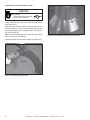
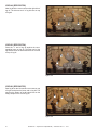
3. Discard the Heat-Zone® cover plate and insulation
piece that was cut out. See Figure 7.3. With a selftapping screw or drill bit, drill out the three holes on the
cover plate of the appliance. This will make it easier to
mount the Heat-Zone® Gas collar.
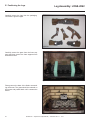
B. Installing the Optional Heat-Zone® Gas
Kit
Before installing finishing materials, use these instructions to
attach the Heat-Zone® Gas kit to the top of the QV36A-FB.
CAUTION
Sharp Edges
• Wear protective gloves and safety
glasses during installation.
COVER PLATE HOLES
1. Remove the four screws that attach the Heat Zone®
Cover Plate to the top of the appliance.
Figure 7.3.
REMOVE SCREWS
4. Remove the four screws securing the cover plate to
the inside of the appliance and discard them along
with the cover plate. See Figure 7.4.
Figure 7.1. Remove Screws.
2. Bend the four pre-cut tabs up to expose the top of the
appliance. Place the Heat-Zone® cover plate on the
insulation inside the unit centered between the three
pre-cut tabs that are the same size as shown in Figure
7.2. Use the Heat-Zone® cover plate as a template
and cut around it carefully with a utility knife.
20
Figure 7.4.
Quadra-Fire • Expression 36 (QV36A-FB) • 2062-900 Rev. S • 11/11
5. Attach the collar that is included with the Heat-Zone®
Gas Kit.
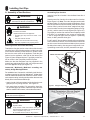
C. Securing and Leveling the Appliance
WARNING
Fire Risk.
• Prevent contact with sagging, loose insulation.
• Do NOT install against combustible materials
such as exposed insulation, plastic and insulation
backer.
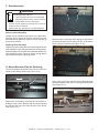
The diagram shows how to properly position, level, and
secure the appliance (see Figure 7.8). Nailing tabs are provided to secure the appliance to the framing members.
• Venting - refer to Vent Clearances and Framing (Section
6) for hole location.
Figure 7.5. Heat-Zone-Gas Collar Installed.
• Place the appliance into position.
6. Attach the insulated flex that is included in the HeatZone® Gas kit with the provided hose clamp.
• Level the appliance from side to side and front to back.
• Shim the appliance as necessary. It is acceptable to use
wood shims.
• Bend out nailing tabs on each side.
• Keep nailing tabs flush with the framing.
• Secure the appliance to the framing by using nails or
screws through the nailing tabs.
WARNING
Figure 7.6. Install Insulated Flex.
7. Close the top of the appliance by bending the four precut tabs back to their original orientation as shown in
Figure 7.7.
Fire Risk.
• ALWAYS maintain specified
clearances around the appliance.
• Do NOT notch into the framing around the appliance spacers.
Failure to keep insulation, framing or other material away from
the appliance may cause fire.
COVER PLATES
STEEL BACK
SUPPORT
Figure 7.7. Bend Pre-cut Tabs Down.
Figure 7.8 Proper positioning, leveling and securing of an
appliance
Quadra-Fire • Expression 36 (QV36A-FB) • 2062-900 Rev. S • 11/11
21
NON-COMBUSTIBLE
FACING MATERIAL
(SUPPLIED ATTACHED
TO BACK OF APPLIANCE).
STEEL BACK SUPPORT
(SUPPLIED ATTACHED TO
TOP OF APPLIANCE).
APPLY FASTENERS FROM
FASTENER PACKET IN
THESE AREAS
Figure 7.9 Attaching Non-combustible Facing Material
D. Installing Non-combustible Facing Material
44 in.
1117 mm
WARNING
Fire Risk.
• Follow these instructions exactly.
• Facing materials must be installed properly to
prevent fire.
• No materials may be substituted without
authorization by Hearth & Home Technologies.
Non-combustible
Zone
18-1/4 in.
463 mm
• Center and attach two top boards to the framing
members. See Figure 7.10.
• Use fasteners from fastener packet (in manual bag) in
shaded areas.
34-5/8 in.
879 mm
• Use regular sheetrock screws in non-shaded areas.
• Use a wet or dry towel or soft brush to remove dust or
dirt from facing material.
• Apply a non-combustible adhesive to attach tile,
stone or other non-combustible finishing materials per
manufacturer’s instructions.
22
Figure 7.10 Complete Installation of Non-combustible
Facing Material
Quadra-Fire • Expression 36 (QV36A-FB) • 2062-900 Rev. S • 11/11
8
Installing Vent Pipe
A. Assembly of Vent Sections
WARNING
Do not mix pipe, fittings or joining
methods from different manufacturers.
WARNING
Fire Risk
Exhaust Fumes Risk
Impaired Performance of Appliance
• Overlap pipe slip sections at least 1-1/2
inches.
• Use pilot holes for screws.
• Screws must not exceed one inch long.
• Pipe may separate if not properly joined.
Attaching Vent to the Firebox Assembly
To attach the first pipe section to the collars, slide the male
end of the inner vent of the pipe section over the inner collar
on the firebox assembly. At the same time, slide the outer
flue over the outer collar on the appliance. Push the pipe
section into the appliance collar until all the lances (see
Figure 8.2) have snapped in place. Tug slightly on the section to confirm it has completely locked into place.
Make sure that the fiberglass rope ring supplied in the
manual bag seals between the first vent component and
the outer appliance wrap (see Figure 8.1)
Assembling Pipe Sections
Insert the inner flue of section A into the flared inner flue of
section B.
Start the outer flue of section A over the outer flue of section
B (see Figure 8.3). Note: The end of the pipe sections with
the lances/tabs on it will face towards the appliance. Once
both inner and outer flues are started, press section A onto
section B firmly until all lances have snapped into place.
Check to make sure they have snapped together (see Figure 8.4) and the seams are not aligned (see Figure 8.5).
Tug slightly on section A to confirm it has completely locked
into place. It is acceptable to use screws no longer than
1 inch to hold outer pipe sections together. If predrilling
holes, do NOT penetrate inner pipe.
For 90° and 45° elbows that are changing the vent direction
from horizontal to vertical, one screw minimum should be
put in the outer flue at the horizontal elbow joint to prevent
the elbow from rotating. Use screws no longer than 1 inch.
If predrilling screw holes, do NOT penetrate inner pipe.
FIRST VENT COMPONENT
FIBERGLASS ROPE RING
Commercial, Multi-family (Multi-level exceeding two
stories), & High-Rise Applications
For Installation into Commercial, multi-family (multi-level exceeding two stories) or high-rise applications: All pipe joints
must be sealed with silicone with a minimum of 300ºF continuous exposure rating, including the slip section that connects
directly to the horizontal termination cap.
• Apply a bead of silicone sealant inside the female outer
pipe joint prior to joining sections. See Figure 8.2
• Only outer pipes are sealed. Do not seal the inner flue.
All unit collar, pipe, slip section, elbow and cap outer flues
shall be sealed in this manner, unless otherwise stated.
Note: The end of the pipe sections with the lances/tabs on
it will face toward the appliance.
Figure 8.1 Fiberglass Rope Ring
High Temperature Silicone Sealant
Commercial, Multi-family (multi-level exceeding two
stories), or High-rise Applications only
WARNING
Fire Risk
Explosion Risk
If slip section seals are broken during the
removal of the termination cap, gas will leak and
a fire or explosion may occur.
Do not break silicone seals on slip sections.
Figure 8.2 Lances
Quadra-Fire • Expression 36 (QV36A-FB) • 2062-900 Rev. S • 11/11
23
Assembling DVP-12A Slip Sections
The outer flue of the slip section should slide over the outer
flue of the pipe section and into (inner flue) the last pipe
section (see Figure 8.7) .
A
Slide together to the desired length, making sure that a
1-1/2 inch outer flue overlap is maintained between the
pipe section and slip section.
The pipe and slip section need to be secured by driving
two screws through the overlapping portions of the outer
flues using the pilot holes (see Figure 8.8).
B
Figure 8.4
Figure 8.3
Note: Make sure that the seams are not aligned to prevent
unintentional disconnection.
This will secure the slip section to the desired length and
prevent it from separating. The slip section can then be
attached to the next pipe section.
If the slip section is too long, the inner and outer flues of
the slip section can be cut to the desired length.
Cut from this end
(outer)
CORRECT
(inner)
Cut from this end
Figure 8.6
Figure 8.5 Seams
INCORRECT
Pilot hole
Assembling Minimum Installations (MI) Sections
MI sections are non-unitized so that they can be cut to a
certain length. Cut these sections to length from the nonexpanded end (see Figure 8.6).
Figure 8.7 Slip Section Pilot Holes
They can then be attached by first connecting the expanded
end of the MI inner flue with the inner pipe from the adjacent
pipe section and securing with three screws. The expanded
portion of the MI inner flue must overlap completely with
the unexpanded end of the adjacent pipe section.
The outer flue can then be inserted into the adjacent outer
flue expanded end and attached to the next pipe section
with three screws. The other end of the MI pipe section can
then be attached by fitting another pipe section to it and
snapping it together, as normal.
Figure 8.8 Screws into Slip Section
24
Quadra-Fire • Expression 36 (QV36A-FB) • 2062-900 Rev. S • 11/11
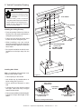
Securing the Vent Sections
B. Disassembly of Vent Sections
Vertical Sections
Vertical sections of pipe must be supported every 8 feet
after the 25 foot maximum unsupported rise. The vent support or plumber’s strap (spaced 120° apart) may be used
to do this (see Figure 8.9).
To disassemble any two pieces of pipe, rotate either section
(see Figure 8.11), so that the seams on both pipe sections
are aligned (see Figure 8.12). They can then be carefully
pulled apart.
WARNING
Horizontal Sections
Horizontal sections of vent must be supported every 5 feet
with a vent support or plumber’s strap.
Fire Risk.
Explosion Risk.
Combustion Fume Risk.
Use vent run supports per installation
instructions.
Connect vent sections per installation
instructions.
• Maintain all clearances to combustibles.
• Do NOT allow vent to sag below
connection point to appliance.
Improper support may allow vent to sag or separate.
Figure 8.9 Securing Vertical Pipe Sections
Figure 8.11 Rotate Seams for Disassembly
Figure 8.10 Securing Horizontal Pipe Sections
Figure 8.12 Align and Disassemble Vent Sections
Quadra-Fire • Expression 36 (QV36A-FB) • 2062-900 Rev. S • 11/11
25
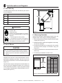
C. Installing Heat Shield and Horizontal Termination Cap
WARNING
Fire Hazard
Impaired performance of appliance
• Telescoping flue section of termination cap
MUST be used when connecting pipe section
to termination cap.
• Maintain a 1-1/2 inch minimum overlap on
telescoping flue section of termination cap.
Installing the Horizontal Termination Cap
Vent termination must not be recessed in the wall. Siding
may be brought to the edge of the cap base.
Flash and seal as appropriate for siding material at outside
edges of cap.
When installing a horizontal termination cap, follow the cap
location guidelines as prescribed by current ANSI Z223.1
and CAN/CGA-B149 installation codes.
WARNING
WARNING
Burn Risk
• Local codes may require installation of a cap
shield to prevent anything or anyone from
touching the hot cap.
Fire Risk
Exhaust Fumes Risk
Impaired Performance of Appliance
• Overlap pipe slip sections at least 1-1/2 inches.
• Use pilot holes for screws.
• Screws must not exceed 1 inch long.
• Pipe may separate if not properly joined.
REAR VENT
HEAT SHIELD
1-1/2 IN. (38 MM) MIN.
OVERLAP
HEAT SHIELD OR
EXTENDED
HEAT SHIELD
WALL SHIELD FIRESTOP
Heat Shield Requirements for Horizontal Termination
For all horizontally vented appliances, a heat shield MUST
be placed one inch above the top of the vent between the
wall shield firestop and the base of the termination cap.
There are two sections of the heat shield. One section
is factory-attached to the wall shield firestop. The other
section is factory-attached to the cap. See Figure 8.13.
If the wall thickness does not allow the required 1-1/2 inch
(38 mm) heat shield overlap when installed, an extended
heat shield (DVP-HSM-B) must be used.
Important Notice: Heat shields may not be field constructed.
The extended heat shield (DVP-HSM-B) may need to
be cut to length. You will attach the cut heat shield to
the existing cap heat shield or wall shield firestop heat
shield (refer to Figure 8.13) using the supplied screws.
You MUST maintain a 1-1/2 in. (38 mm) overlap of the
extended heat shield and the existing shields (both ends
of the heat shield). The small leg on the extended heat
shield should rest on the top of the vent (pipe section) to
properly space it from the pipe section.
26
INNER VENT
INTERIOR
SHEATHING
EXTERIOR
OUTER VENT
HEAT SHIELD EXTENSION NOT SHOWN.
Figure 8.13 Venting through the Wall
NOTE: Where required, an exterior wall flashing is available.
When penetrating a brick wall, a brick extension kit is available
for framing the brick.
Quadra-Fire • Expression 36 (QV36A-FB) • 2062-900 Rev. S • 11/11
D. Installing Roof Flashing and Vertical Termination Cap
For installation of vertical termination cap see minimum
vent heights for various pitched roofs (see Figure 8.14).
HORIZONTAL
OVERHANG
2 FT.
MIN.
20 INCHES MIN.
VERTICAL
WALL
LOWEST
DISCHARGE
OPENING
GAS DIRECT VENT
TERMINATION CAP
Caulk the gap between the roof flashing and the outside
diameter of the pipe. Also caulk the perimeter of flashing
that contacts roof surface and the overlap seam of any
exposed pipe sections that are located above the roof line
as shown in Figure 8.16.
To attach the vertical termination cap, slide the inner collar of the cap into the inner flue of the pipe section and
place the outer collar of the cap over the outer flue of the
pipe section.
Secure with three screws into the outer flue. Secure the cap
by driving the three self-tapping screws (supplied) through
the pilot holes in the outer collar of the cap into the outer
flue of the pipe (see Figure 8.15).
X
12
TERMINATION CAP
ROOF PITCH
IS X/ 12
H (MIN.) - MINIMUM HEIGHT FROM ROOF
TO LOWEST DISCHARGE OPENING
Roof Pitch
H (Min.) Ft.
Flat to 6/12........................................ 1.0*
Over 6/12 to 7/12 ............................ 1.25*
Over 7/12 to 8/12 .............................. 1.5*
Over 8/12 to 9/12 .............................. 2.0*
Over 9/12 to 10/12 ............................. 2.5
Over 10/12 to 11/12 ......................... 3.25
Over 11/12 to 12/12 ........................... 4.0
Over 12/12 to 14/12 ........................... 5.0
Over 14/12 to 16/12 ........................... 6.0
Over 16/12 to 18/12 ........................... 7.0
Over 18/12 to 20/12 ........................... 7.5
Over 20/12 to 21/12 ........................... 8.0
(1 of 3)
STORM
COLLAR
SCREWS
CAULK
* 3 foot minimum in snow regions
Figure 8.14 Minimum height from roof to lowest discharge
opening
Figure 8.15
WARNING
Fire Risk.
Explosion Risk.
Inspect external vent cap regularly.
• Ensure no debris blocks cap.
• Combustible materials blocking cap may
ignite.
• Restricted air flow affects burner operation.
CAULK
NOTICE: Failure to properly caulk the roof flashing and
pipe seams may permit entry of water.
Figure 8.16
Quadra-Fire • Expression 36 (QV36A-FB) • 2062-900 Rev. S • 11/11
27
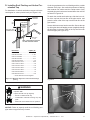
Assembling and Installing Storm Collar
CAUTION
Sharp Edges
• Wear protective gloves and safety
glasses during installation.
Connect both halves of the storm collar with two screws
(see Figure 8.17).
Wrap the storm collar around the exposed pipe section
and align brackets. Insert a bolt (provided) through the
brackets and tighten nut to complete storm collar assembly (see Figure 8.18).
Slide the assembled storm collar down the pipe section
until it rests on the roof flashing.
Figure 8.18 Assembling the Storm Collar Around the Pipe
Caulk around the top of the storm collar (see Figure 8.15).
Figure 8.17 Assembling the Storm Collar
28
Quadra-Fire • Expression 36 (QV36A-FB) • 2062-900 Rev. S • 11/11
9
Gas Information
A. Fuel Conversions
C. Gas Connection
Before making gas connections ensure that appliance being installed is compatible with the available gas type.
Any natural or propane gas conversions necessary to
meet the appliance and locality needs must be made by
a qualified technician using Hearth & Home Technologies
specified and approved parts.
Note: Have the gas supply line installed in accordance
with local building codes, if any. If not, follow ANSI
223.1. Installation should be done by a qualified installer
approved and/or licensed as required by the locality. (In
the Commonwealth of Massachusetts installation must be
performed by a licensed plumber or gas fitter).
B. Gas Pressures
Proper input pressures are required for optimum appliance performance. Gas line sizing requirements need to
be made following NFPA54.
WARNING
Fire Risk.
Explosion Hazard.
High pressure will damage valve.
• Disconnect gas supply piping BEFORE
pressure testing gas line at test pressures
above 1/2 psig.
• Close the manual shutoff valve BEFORE
pressure testing gas line at test pressures
equal to or less than 1/2 psig.
Note: A listed (and Commonwealth of Massachusetts approved) 1/2 inch (13 mm) T-handle manual shut-off valve and
flexible gas connector are connected to the 1/2 inch (13 mm)
control valve inlet.
• If substituting for these components, please consult
local codes for compliance.
Refer to Reference Section 16 for location of gas line
access in appliance.
Note: Gas line may be run from either side of the appliance
provided the hole in the outer wrap does NOT exceed 2-1/2
inches in diameter and does not penetrate the firebox.
WARNING
Gas Leak Risk
• Support control when attaching pipe to
prevent bending gas line.
WARNING
Verify inlet pressures.
• High pressure may cause overfire condition.
• Low pressure may cause explosion.
• Verify minimum pressures when other
household gas appliances are operating.
Install regulator upstream of valve if line
pressure is greater than 1/2 psig.
Note: The gap between supply piping and gas access
hole may be caulked with caulk with a minimum of 300ºF
continuous exposure rating or stuffed with non-combustible,
unfaced insulation to prevent cold air infiltration.
Pressure requirements for appliance are shown in the
table below. Minimum pressures must be met when other
household gas appliances are operating.
Pressure
Natural Gas
Propane
Minimum inlet pressure
5.0 inches
w.c.
11.0 inches
w.c.
Maximum inlet gas pressure
14.0 inches
w.c.
14.0 inches
w.c.
Manifold pressure
3.5 inches
w.c.
10.0 inches
w.c.
Quadra-Fire • Expression 36 (QV36A-FB) • 2062-900 Rev. S • 11/11
29
• Ensure that gas line does not come in contact with outer
wrap of appliance. Follow local codes.
• Incoming gas line should be piped into the valve
compartment and connected to the 1/2 inch connection
on the manual shutoff valve.
WARNING
Fire or Explosion Hazard
•
•
•
•
Gas buildup during line purge may ignite.
Purge should be performed by qualified technician.
Ensure adequate ventilation.
Ensure there are no ignition sources such as
sparks or open flames.
HIGH ALTITUDE INSTALLATIONS
U.L. Listed gas appliances are tested and approved without
requiring changes for elevations from 0 to 2000 feet in the
U.S.A. and Canada.
When installing this appliance at an elevation above 2000 feet,
it may be necessary to decrease the input rating by changing
the existing burner orifice to a smaller size. Input rate should
be reduced by 4% for each 1000 feet above a 2000 foot
elevation in the U.S.A., or 10% for elevations between 2000
and 4500 feet in Canada. If the heating value of the gas has
been reduced, these rules do not apply. To identify the proper
orifice size, check with the local gas utility.
If installing this appliance at an elevation above 4500 feet (in
Canada), check with local authorities.
• A small amount of air will be in the gas supply lines.
When first lighting appliance it will take a short time for
air to purge from lines. When purging is complete the
appliance will light and operate normally.
WARNING
CHECK FOR GAS LEAKS
Explosion Risk
Fire Risk
Asphyxiation Risk
• Check all fittings and connections.
• Do not use open flame.
• After the gas line installation is complete, all
connections must be tightened and checked
for leaks with a commercially-available,
non-corrosive leak check solution. Be sure
to rinse off all leak check solution following
testing.
Fittings and connections may have loosened
during shipping and handling.
WARNING
Fire hazard.
Do NOT change the valve settings.
• This valve has been preset at the factory.
• Changing valve settings may result in fire
hazard or bodily injury.
30
Quadra-Fire • Expression 36 (QV36A-FB) • 2062-900 Rev. S • 11/11
10
Electrical Information
A. Recommendation for Wire
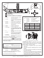
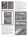
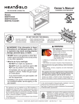
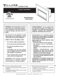
C. IntelliFire Ignition System Wiring
This appliance requires 110-120 VAC be wired to the
junction box either for use of optional accessories or for
proper operation of the appliance.
This appliance requires a 110 VAC supply to the appliance junction box for operation. A wiring diagram is shown
in Figure 10.1.
Note: This appliance must be electrically wired and grounded
in accordance with local codes or, in the absence of local
codes, with National Electric Code ANSI/NFPA 70-latest
edition or the Canadian Electric Code, CSA C221.1.
This appliance is equipped with an IntelliFire control valve
which operates on a 3 volt system.
This appliance is supplied with a battery pack and a 3 volt
AC transformer, which requires the installation of the supplied junction box. It is highly recommended that the junction box be installed at this time to avoid reconstruction.
• A 110-120 VAC circuit for this product must be protected
with ground-fault circuit-interrupter protection, in
compliance with the applicable electrical codes, when it is
installed in locations such as in bathrooms or near sinks.
The battery pack requires two D cell batteries (not included). Batteries cannot be placed in the battery pack while
using the 3 volt AC transformer. Conversely, the transformer must be unplugged if the battery pack is used.
B. Connecting to the Appliance
WARNING
CAUTION
Wire 110V to electrical junction box.
Do NOT wire 110V to valve.
Do NOT wire 110V to wall switch.
• Incorrect wiring will damage millivolt valves.
• Uninterrupted or continuous power is required
at all times in IPI system EXCEPT when using
battery back-up.
• Incorrect wiring will override IPI safety lockout and may
cause explosion.
Battery polarity must be correct or module damage will
occur.
WIRES WITH LABEL “FOR USE WITH REMOTE OR WALL SWITCH ONLY”
(LOCATED UNDER FIREPLACE)
BATTERIES
RED
YELLOW (HNG)
WHITE (HTL)
BATTERY
1
2
3
4
5
6
7
8
3V DC
REAR VIEW
GREEN
IPI PILOT
BROWN
BROWN
RED
BROWN
BROWN
RED
G
Y
R
BLACK
RED
(MALE/FEMALE)
FLAME
SOLENOID
RED
(FEMALE/MALE)
IPI
MODULE
RED
BLACK
IPI
VALVE
GROUND
BLACK
R
Y
G
BLACK
GREEN
ORANGE
FRONT VIEW
FLAME ON
RED
RED
ORANGE
FLAME HIGH/LOW
ADAPTER WIRES
ORANGE
AC
PLUG
BLACK
GROUND
PIGTAIL
GREEN
AUX
CONNECTION
BLACK
FAN
REM/AUX
TRANS
GROUND
NEUTRAL
CONTINUOUS
110VAC
SUPPLY
FAN
CONNECTION
Note 1: Ignition module, valve, pilot
and wall switch operate on 3 volts.
HOT
WHITE
FACTORY
CONNECTED
TOGETHER
FAN THERMOSTAT
BLACK
FIREBOX LIGHTS
YELLOW
YELLOW
Note 2: Plug QWSK-MLT wall switch
kit into the REM/AUX outlet on the
junction box.
Figure 10.1 IntelliFire Pilot Ignition (IPI) Wiring Diagram
Quadra-Fire • Expression 36 (QV36A-FB) • 2062-900 Rev. S • 11/11
31
D. Optional Accessories Requirements
E. QWSK-MLT Wall Switch Kit
Wiring for optional accessories should be done now to
avoid reconstruction.
Introduction
CAUTION
Label all wires prior to disconnection when servicing controls.
Wiring errors can cause improper and dangerous operation.
Verify proper operation after servicing.
WARNING
Shock hazard.
• Replace damaged wire with type 105º C rated
wire.
• Wire must have high temperature insulation.
The QWSK-MLT multifunctional wall switch is designed
to control flame height, blower speed, and auxiliary
functions on your gas fireplace. For models equipped with
the Intellifire system (IPI), the cold climate function can
control the pilot flame as well. The wall switch is equipped
with thermostat functions which can automatically control
the temperature in the room in which it is installed. The
wall switch interfaces with both intermittent and standing
pilot systems. An auxiliary function provides 110-120
VAC source for added features the fireplace may have
installed. Electrical ratings for the control box are 110
VAC, 60 Hz, and is required for operation of this device.
Installation precautions
To Replace a Light Bulb:
This remote is tested and safe when installed in accordance
with this installation manual. It is your responsibility to
read all instructions before starting installation and to
follow these instructions carefully during installation. Do
not install any components that may be damaged. Do not
modify, disassemble, or substitute any of the components
included with this kit. Installation of this unit must be done
by a qualified service technician.
The lights are shipped in boxes in the light enclosures.
Reach behind the valve and locate the light boxes. Cut
the rubber band and slide out the back of the light box.
Remove the light bulb from the box and install it in the
socket. Replace the back of the enclosure.
Placement of this wall switch may affect performance
or accuracy of the automatic (thermostat) control. An
assessment of the space should be done prior to
installation for optimal performance. See the installation
instructions section I for recommendations.
LIGHT BULBS
This appliance has standard firebox lighting. The 20 watt
halogen bulbs are not factory installed. The lights are accessible from under the firebox in the valve area.
NOTE: The electrical junction box provided with the
fireplace must be wired with 110 VAC.
All wiring should be done by a qualified electrician and
shall be in compliance with local codes and with the
National Electric Code ANSI/NFGA No. 70- current (in the
United States), or with the current CSA C22.1 CANADIAN
ELECTRIC CODE (in Canada).
WARNING
Shock Hazard
Do not provide any power to this unit until all
wiring is completed. Failure to do so may destroy
parts of this device and render it unusable, and
may lead to possible electrical shock.
Fire Hazard
Figure 10.2 Light enclosure
32
Modification of any parts or installation of
damaged components will void the warranty,
and you may possibly cause a fire hazard.
Quadra-Fire • Expression 36 (QV36A-FB) • 2062-900 Rev. S • 11/11
CONTROL
WIRE
WALL SWITCH
FLAME
SOLENOID
COVER
PLATE
CONTROL
BOX
Wiring the wall switch
Once a location is chosen and the electrical box is
installed proceed as follows. Install the provided control
wire from the fireplace to the switch location. Use
caution not to stress the wire around tight or sharp
corners. Do not run the control wire adjacent to existing
or future phone, data, cable, or electrical lines. The
wire should not come into contact with any part of the
fireplace exterior with the exception of where it exits the
outer wrap. Feed the wire to the electrical junction box
and through a provided or approved strain relief. Using a
screw driver, connect the red wire to the “R” terminal, the
yellow or white wire to the “W” or “Y” terminal, and the
green wire to the “G” terminal. Do not over-tighten. Using
the screws provided, mount the switch to the electrical
junction box right side up. Install provided cover plate
using the screws provided. Do not use a substitute cover
even though it may fit. The provided one is specifically
designed for the automatic (thermostat) function of the
unit.
Operating Instructions
Figure 10.3.
For units WITH factory installed rocker switch.
Installation instructions
Determine location
Determine the location for the wall switch. The chosen
location should provide an accessible location in the
same space as the gas fireplace. Never place this unit in a
separate room. The control wire supplied with this switch
is 33 ft (10M) in length. The distance from the fireplace
to the switch may be lengthened provided that the wire
used never exceeds 50 ft, and that the distance from the
fireplace to the switch never exceeds 30 ft.
The ON/OFF rocker switch on the fireplace (located near
the gas valve) must be in the “OFF” position for use with
the WSK-MLT system. The ON/OFF rocker switch will
NOT function with this device on Intellifire (IPI) models
except during a power outage.
NOTE: The temperature displayed by the wall switch may
take up to 30 minutes to stabilize on initial power-up.
NOTE: Check control box and assure switch is in the “OFF”
position. This switch is only used on Intellifire (IPI) control
systems under battery operation.
The switch should be mounted into a listed electrical
junction box. The junction box should be dedicated to this
wall switch. Never install this wall switch into a junction box
that is shared with other electrical service or devices. If
possible, install this unit on an interior wall of the residence
at a recommended height of 5 ft from the flooring. Should
the switch be installed on an exterior wall, be certain wall
insulation is kept intact and not damaged or dislodged
during the installation of the electrical junction box.
For exterior wall installations, it is recommended that the
junction box be sealed with caulking material. This will
minimize heat loss through this location and improve the
accuracy of the automatic (thermostat) operation.
Figure 10.4
Quadra-Fire • Expression 36 (QV36A-FB) • 2062-900 Rev. S • 11/11
33
Setting Flame Height/manifold pressure
<>
(To be done by a qualified service technician). Upon initial
power-up of this device, valve pressure must be set for
flame adjustment.
• Push to adjust set point temperature under automatic
control.
• Loosen output pressure tap on valve and connect with
pressure manometer.
• Press flame button once (Fig. 10.4); fireplace will light
with flames on high.
• Turn solenoid clockwise to increase pressure,
counterclockwise to decrease pressure until manifold
pressure on high is 3.5” water column for natural gas
(NG), 10.0” water column for propane (LP).
• Once pressure is achieved spin jam-nut on solenoid
stem tight against regulator face to prevent rotation. Do
not overtighten.
• Press flame button twice to turn fireplace off.
• Remove manometer tube and tighten or close pressure
tap. Use a soap solution to carefully check the pressure
tap for leaks.
Wall Switch Button Operation
See Figure 10.4.
Up and Down Arrows
AUX Auxiliary Button
• Button Press: Turns on auxiliary power
• Button Press: Turns off auxiliary power
Can be operated independently of all functions.
Child Proof Mode
To Enter Child Proof Mode:
• Press the Up Arrow Button twice and Down Arrow Button
once. The unit will send out 3 beeps and an indicator in
the LCD panel will show that the child proof is on.
To Leave Child Proof Mode:
• Press the Up Arrow Button twice and Down Arrow Button
once. The unit will send out 3 beeps and the indicator in
the LCD panel that shows that the child proof is on will
disappear.
Flame Button
• Button Press: Unit On / Flames High, Turns on auxiliary
power
• Button Press: Flames Low
• Button Press: Unit Off / Flames Off, Turns off auxiliary
power
NOTE: When in Child Proof Mode, only the arrow buttons
will have functionality. Unit can enter Child Proof when the
fireplace is on or off.
INTELLIFIRE (IPI) MODELS ONLY
Fan / Blower Button
Cold Climate Button
• Button Press: Fan High (“3”)
• Button Press: Fan Medium (“2”)
• Button Press: Turns on Climate Control
• Button Press: Fan Low (“1”)
• Button Press: Turns off Climate Control
• Button Press: Fan Off
This allows the pilot flame to stay lit when activated, a
benefit of this is reduced condensation on the glass at
start-up in colder climate conditions.
Temperature Button
• Button Press will toggle between Automatic and Manual
Operation
• Press and Hold the button for 3 seconds to toggle between
Fahrenheit and Centigrade Temperature Display.
Automatic Operation: Controller will monitor temperature
and control unit according to the set point.
Manual Operation: Controller will not automatically
change settings.
SET
Set Temperature Button
• Button Press: Displays Set Point
• Use Up and Down Arrows to Adjust Set Point
• Press Set Button to Store New Set Point
Temperature Set Point can be adjusted between the ranges of:
45-900 Fahrenheit or 7-320 Centigrade
NOTE: The controller will turn off the fireplace at 20 F over
set point and turn it back on at 20 F below set point.
34
Operation Under Battery Power
A switch on the control box allows for battery power under
no-power conditions. See Figure 10.6. By controlling the
power supply with this switch, the batteries are supplying
power only when needed, thus extending battery life. The
switch also provides a convenient means for switching to
battery power should there be a loss of 110 VAC power to
the control box.
• In the event of a power failure, switch the battery
operation switch to the “Battery ON” position.
• The fireplace can now be turned on and off with the ON/
OFF rocker switch located near the gas valve.
• The wall switch functions will not operate under battery
power.
• Under battery control the only available function is flame
“On” and “Off” in the high position.
• To maximize battery life, and to restore full function
capability of the wall switch, flip switch to “OFF” position
after 120 VAC power is restored.
Quadra-Fire • Expression 36 (QV36A-FB) • 2062-900 Rev. S • 11/11
F. Junction Box Installation
If the box is being wired from the OUTSIDE of the appliance:
BATTERY
OPERATION
SWITCH
• Remove the cover plate located on the outer shell - right
side (see Figure 10.6).
CONTROL
BOX
• Install the supplied Romex™ connector in the cover plate.
• Feed the necessary length of wire through the connector.
Figure 10.5.
“BATTERY ON”
POSITION
• Make all necessary wire connections and reattach the
cover plate to the outer shell.
If the box is being wired from the INSIDE of the appliance:
• Remove the screw attaching the junction box/receptacle
to the outer shell, rotate the junction box inward to
disengage it from the outer shell (see Figure 10.6).
• Pull the electrical wires from outside the appliance
through this opening into the valve compartment.
• Feed the necessary length of wire through the connector.
• Make all necessary wire connections to the junction box/
receptacle and reassemble the junction box/receptacle
to the outer shell.
Romex
Connector
14/2WG
Cover Plate
outside firebox
HT
W
WHT B
LK
BLK
“OFF”
POSITION
GRN wire
inside box
Copper
ground attached
to GRN screw with
GRN wire
Note: Do NOT wire
110VAC to wall switch.
Figure 10.6 Junction Box Detail
Quadra-Fire • Expression 36 (QV36A-FB) • 2062-900 Rev. S • 11/11
35
11
Finishing
A. Mantel Projections
44 in.
1117 mm
Figure 11.1 shows the minimum vertical and corresponding maximum horizontal dimensions of appliance mantels
or other combustible projections above the top front edge
of the appliance.
NON-COMBUSTIBLE
ZONE
18-1/4 in.
463 mm
3 IN. MIN.
12 IN. MAX.
23 IN.
Figure 11.3 Noncombustible Facing
1 IN. MAX.
14 IN.
18 IN. MIN.
WARNING
12 IN. MIN.
Figure 11.1 Clearances to mantels or other combustibles
above appliance
Risk of Fire
• Non-combustible clearances
MUST be maintained.
• Sheetrock, wood or other combustibles must NOT be used
as sheathing or facing in the non-combustible zone.
• See Section 11 for proper clearances.
• See Section 1 for combustible/non-combustible definitions.
Facing Requirements
This appliance requires the supplied non-combustible facing material from the top of the appliance face up 18-1/4
inches and extending across from framing stud to framing
stud (see Figure 11.3).
5
4
3
2
1
1
2
1/2
4
6
8
Note: All measurements in inches.
Figure 11.2 Mantel leg or Wall projections
(Acceptable on both sides of opening.)
Combustible finishing materials may be used along the
sides of the appliance face but may not overlap the face.
Non-combustible materials can overlap the black metal
face of the unit on the sides, top and bottom, but must never overlap or obstruct the appliance opening or louvers.
Fronts
Remington Avenue fronts are attached to the appliance
with carriage bolts and overlap the face of the appliance.
Tile or other non-combustible materials may be tucked
behind the Remington Avenue front on the top and sides.
Other front options fit inside the appliance.
B. Facing Material
WARNING
WARNING
Fire Risk.
Do NOT obstruct air inlet or outlet grilles.
Do NOT modify grilles.
• Modifying or covering grilles could cause
temperature rise and fire hazard.
Finishing materials must not interfere with:
• Air flow through grilles or louvers.
• Operation of louvers or doors.
• Access for service.
36
•
•
•
•
Fire Risk.
Finish all edges and fronts to clearances and
specifications listed in manual.
Black metal appliance front may be covered with
noncombustible material only.
Do NOT overlap combustible materials onto appliance front.
Install combustible materials only up to specified clearances
on top, front and side.
Seal joints between the finished wall and appliance top and
sides using only a 300º F minimum sealant.
Quadra-Fire • Expression 36 (QV36A-FB) • 2062-900 Rev. S • 11/11
12
Appliance Setup
A. Remove Shipping Materials
Remove shipping materials from inside or underneath the
firebox.
B. Clean the Appliance
Clean/vacuum any sawdust that may have accumulated
inside the firebox or underneath in the control cavity.
C. Accessories
Install approved accessories per instructions included
with accessories. See Service Parts List for appropriate
accessories. Refer to Section 16.
WARNING
Shock or fire risk.
Use ONLY optional accessories approved for
this appliance.
• Using non-listed accessories voids warranty.
• Using non-listed accessories may result in a
safety hazard.
• Only Hearth & Home Technologies approved
accessories may be used safely.
D. Ember Placement
WARNING
Explosion Risk.
• Follow ember placement instructions in manual.
• Do NOT place embers directly over burner ports.
• Replace ember material annually.
Improperly placed embers interferes with proper burner
operation.
Placing the Ember Material
Ember material is shipped with this gas appliance. To place
the ember material:
• Embers CANNOT be placed directly over ports. Care
should be taken not to cover the lighting trail of ports
(from back to front).
• When placing Glowing Embers® onto the burner care
should be taken so that the ports are not covered. Place
the dime-size ember pieces just in front of the port trail,
but not on or in between the ports. Failure to follow
this procedure will likely cause lighting and sooting
problems.
• Place Mystic Embers on areas of base refractory away
from port holes. Use this material to give the appliance
a realistic ash bed.
• Save the remaining ember materials for use during
appliance servicing. The embers provided should be
enough for 3 to 5 applications.
Quadra-Fire • Expression 36 (QV36A-FB) • 2062-900 Rev. S • 11/11
37
E. Positioning the Logs
Log Assembly: LOGS-2062
Carefully remove the logs from the packaging.
CAUTION: Logs are fragile!
1
6
5
3
2
Figure 12.1
Carefully remove the grate from the foam supports and then remove the foam supports from
around the burner.
Figure 12.2
Place grate on the base of the firebox surrounding the burner. The grate should be centered on
the burner and pushed back until it contacts the
burner.
AIR
BAFFLE
Figure 12.3
38
4
Quadra-Fire • Expression 36 (QV36A-FB) • 2062-900 Rev. S • 11/11
LOG #1: (SRV2062-701)
Place log #1 on the back of burner. Rest log on
back of the grate. The notches located on the bottom of the log should rest over the back corners
of burner.
1
Figure 12.4
LOG #2: (SRV2062-702)
Place log #2 on the burner so that the bottom of
the log conforms with the contour of the burner.
The outside of the log should rest on the grate. The
front of the log will rest against the right andiron.
1
2
Figure 12.5
LOG #3: (SRV2062-703)
Place log #3 on the burner in the same way but
on the left front of the burner.
1
3
2
Figure 12.6
Quadra-Fire • Expression 36 (QV36A-FB) • 2062-900 Rev. S • 11/11
39
LOG #4: (SRV330-706)
Nest log #4 in the cut-out area on the right side of
log #1. The thinnest “arm” of log #4 rests on top
of log #2.
4
1
3
2
Figure 12.7
LOG #5: (SRV330-704)
Place the “Y” end of log #5 against the corresponding bump on log #3. The other end of the
log should rest in the second smooth cut-out area
on top of log #1.
4
5
1
2
3
Figure 12.8
LOG #6: (SRV340-705)
Rest log #6 on the left smooth cut-out area on top
of log #1 and place the lower end on log #3. The
notch on the bottom of log #6 should rest on the
wedge shape on the end of log #3.
6
5
1
3
Figure 12.9
40
Quadra-Fire • Expression 36 (QV36A-FB) • 2062-900 Rev. S • 11/11
4
2
F. Glass Assembly
WARNING
Handle glass doors with care.
• Inspect the gasket to ensure it is undamaged.
• Inspect the glass for cracks, chips or scratches.
• Do NOT strike, slam or scratch glass.
• Do NOT operate appliance with glass door removed,
cracked, broken or scratched.
• Replace glass door assembly as a complete appliance.
Removing Glass Assembly
Unlatch the two latches at the bottom of the glass door.
Carefully pull the bottom of the door away from the unit
and lower the top tabs on the door out of the top latches
as tension is relieved.
Replacing Glass Assembly
Figure 12.11
Slide the burner to the right while angling the right side of
the burner forward until the burner is free of the shutter
sleeve, then lift out burner (see Figure 12.12).
Angle the top of the glass door in toward the appliance and
insert the tabs on top of the glass frame into the top latches.
Rotate the bottom of the glass door toward the firebox with
slight upward pressure. Latch the bottom spring latches
securely onto the bottom glass door tabs.
G. Burner Removal (Only for Servicing)
Loosen the shutter adjustment wing nut and move the
shutter to the closed position (see Figure 12.10).
Figure 12.12
Open
Closed
Wing nut
Using a 3/8” nut driver or wrench, remove the natural gas
orifice and replace it with the LP orifice provided in this kit
(see Figure 12.13).
Figure 12.10
Remove the air baffle by removing the two screws attaching it to the burner. Remove the two screws holding
the pilot and the one screw from the front of the burner
(see Figure 12.11).
Orifice Holder
Shutter Sleeve
Burner Neck
Figure 12.13
Quadra-Fire • Expression 36 (QV36A-FB) • 2062-900 Rev. S • 11/11
41
Replace the burner by first tipping the front of the burner
up to get the burner neck started into the shutter sleeve
(see Figure 12.14).
H. Grilles and Trim
Install optional marble and brass trim surround kits as desired. Marble, brass, brick, tile, or other noncombustible
materials can be used to cover up the gap between the
sheet rock and the appliance.
Do not obstruct or modify the air inlet/outlet grilles. When
overlapping on both sides, leave enough space so that the
bottom grille can be lowered and the trim door removed.
I. Air Shutter Setting
This appliance has an adjustable air shutter (which controls the primary air) factory set for the minimum vertical
vent run (see Figure 12.10). If your installation has more
than the minimum required vertical vent length, adjustment of the air shutter may be necessary to obtain optimal
flame appearance. This should be adjusted by a qualified installer at the time of installation.
Figure 12.14
Once the neck is in the sleeve, slide the burner all the way
to the left until the orifice goes into the burner neck and the
neck contacts the orifice holder, and all the way back until
the neck contacts the burner support.
By sliding the air shutter handle to the right, you will be
closing the air shutter. To adjust loosen the wing nut. Care
should be taken when adjusting the air shutter so as not
to cause the appliance to soot. If sooting occurs the air
shutter will need to be opened by sliding the handle to the
left. When finished tighten wing nut.
While sliding the burner into position, make sure the pilot
is not pushed aside and it is lined up for reattaching to the
burner (see Figure 12.15).
Figure 12.15
Replace the screw in front of the burner to the burner
bracket. Reattach the pilot assembly with two screws.
Reattach the air baffle, sliding it back to contact the
back of the firebox and replacing two screws (see Figure
12.11).
Move the air shutter to the open position and tighten the
wing nut to secure it (see Figure 12.10).
42
Quadra-Fire • Expression 36 (QV36A-FB) • 2062-900 Rev. S • 11/11
13
Operating Instructions
A. Before Lighting Appliance
This appliance has an IntelliFire ignition system.
CAUTION
WARNING
HOT SURFACES!
Glass and other surfaces are hot during
operation AND cool down.
If installing IntelliFire ignition battery backup:
• Do not install batteries if the backup mode may not be
used for extended time.
• Batteries may leak.
• Install batteries only when needed for power outage.
Hot glass will cause burns.
• DO NOT touch glass until it is cooled
• NEVER allow children to touch glass
• Keep children away
• CAREFULLY SUPERVISE children in same room as
fireplace.
• Alert children and adults to hazards of high temperatures.
Before operating this appliance have a qualified technician:
High temperatures may ignite clothing or other
flammable materials.
• Keep clothing, furniture, draperies and other flammable
materials away.
• Remove all shipping materials from inside and/or
underneath the firebox.
• Review proper placement of logs, rockwool, lava rock,
and vermiculite.
This appliance has been supplied with an integral barrier
to prevent direct contact with the fixed glass panel. DO
NOT operate the appliance with the barrier removed.
Contact your dealer or Hearth & Home Technologies if the
barrier is not present or help is needed to properly install one.
• Check the wiring.
• Check the air shutter adjustment.
• Ensure that there are no gas leaks.
• Ensure that the glass is sealed and in the proper
position.
• Ensure that the flow of combustion and ventilation air is
not obstructed (front grilles and vent caps).
WARNING
Glass door must be in place when
appliance is operating.
Risk of:
• Combustion Fumes
• Fire
Do NOT operate appliance with glass
door removed.
• Open viewing glass for servicing only.
WARNING
Improper installation, adjustment, alteration, service or
maintenance can cause injury or property damage. Refer to
the owner’s information manual provided with this appliance.
For assistance or additional information consult a qualified
installer, service agency or the gas supplier.
WARNING
Do NOT use this appliance if any part has been under water.
Immediately call a qualified service technician to inspect the
appliance and to replace any part of the control system and
any gas control which has been under water.
• Glass door MUST be in place and sealed before operating
appliance.
• Only use glass door certified for use with appliance.
• Glass replacement should be done by qualified technician.
Quadra-Fire • Expression 36 (QV36A-FB) • 2062-900 Rev. S • 11/11
43
B. Lighting Appliance
IPI Ignition
FOR YOUR SAFETY
READ BEFORE LIGHTING
LIGHTING
INSTRUCTIONS (IPI)
WARNING: If you do not follow these instructions exactly, a fire or explosion
may result causing property damage, personal injury or loss of life.
1. This appliance is equipped with an ignition
device which automatically lights the burner.
DO NOT try to light the burner by hand.
A. This appliance is equipped with an
intermittent pilot ignition (IPI) device
which automatically lights the burner. DO NOT try to light the burner by
hand.
• Immediately call your gas supplier
from a neighbor’s phone. Follow the
gas supplier’s instructions.
B. BEFORE LIGHTING, smell all around
the appliance area for gas. Be sure to
smell next to the floor because some
gas is heavier than air and will settle
on the floor.
C. DO NOT use this appliance if any
part has been under water. Immediately call a qualified service technician to inspect the appliance and
to replace any part of the control
system and any gas control which
has been under water.
WHAT TO DO IF YOU SMELL GAS
• DO NOT try to light any appliance.
• If you cannot reach your gas supplier, call the fire department.
Equipped with wall switch: Turn ON/OFF switch
to ON.
WARNING:
CAUTION:
DO NOT CONNECT LINE VOLTAGE (110/120 VAC OR 220/240
VAC) TO THE CONTROL VALVE.
Hot while in operation. DO NOT touch.
Keep children, clothing, furniture, gasoline and other liquids having flammable
vapors away.
This appliance needs fresh air for
safe operation and must be installed
so there are provisions for adequate
combustion and ventilation air.
If not installed, operated, and maintained in accordance with the manufacturer’s instructions, this product could
expose you to substances in fuel or
fuel combustion which are known to the
State of California to cause cancer, birth
defects, or other reproductive harm.
Keep burner and control compartment
clean. See installation and operating
instructions accompanying appliance.
2. Wait five (5) minutes to clear out any gas.
Then smell for gas, including near the floor. If
you smell gas, STOP! Follow “B” in the Safety
Information located on the left side of this label. If you do not smell gas, go to next step.
3. To light the burner:
• DO NOT touch any electric switch; do
not use any phone in your building.
Improper installation, adjustment, alteration, service or maintenance can
cause injury or property damage. Refer to the owner’s information manual
provided with this appliance.
GAS
VALVE
DO NOT operate the appliance with
fixed glass assembly removed, cracked
or broken. Replacement of the fixed
glass assembly should be done by a
licensed or qualified service person.
NOT FOR USE
WITH SOLID FUEL
For use with natural gas and propane.
A conversion kit, as supplied by the
manufacturer, shall be used to convert
this appliance to the alternate fuel.
Equipped with remote or wall control: Press
ON or FLAME button.
Equipped with thermostat: Set temperature to
desired setting.
4. If the appliance does not light after three tries,
call your service technician or gas supplier.
TO TURN OFF
GAS TO APPLIANCE
1. Equipped with wall switch: Turn ON/OFF switch
to OFF.
Equipped with remote or wall control: Press
OFF button.
Equipped with thermostat: Set temperature to
lowest setting.
2. Service technician should turn off electric
power to the control when performing service.
Also Certified for Installation in a
Bedroom or a Bedsitting Room.
For assistance or additional information, consult a qualified installer, service agency or the gas supplier.
For additional information on operating your
Hearth & Home Technologies fireplace, please refer to www.fireplaces.com.
Final inspection by
44
Quadra-Fire • Expression 36 (QV36A-FB) • 2062-900 Rev. S • 11/11
593-913G
C. After Appliance is Lit
CAUTION
Initial Break-in Procedure
When you light the appliance, you may notice that it produces heat which does have an associated odor or smell.
If you feel this odor is excessive it may require the initial
three to four hour continuous burn on high followed by a
second burn up to 12 hours to fully drive off any odor from
paint and lubricants used in the manufacturing process.
Condensation of the glass is normal.
Note: The appliance should be run three to four hours
on the initial start-up. Turn it off and let it cool completely.
Remove and clean the glass. Replace the glass and run
the appliance for an additional 12 hours. This will help to
cure the products used in the paint and logs.
During this break-in period it is recommended that some
windows in the house be opened for air circulation. This will
help avoid setting off smoke detectors, and help eliminate any
odors associated with the appliance’s initial burning.
• Prevent accidental appliance operation when not
attended.
• Unplug or remove batteries from remote control if absent
or if appliance will not be used for an extended period of
time.
• Property damage possible from elevated temperatures.
CAUTION
Smoke and odors released during initial operation.
• Open windows for air circulation.
• Leave room during initial operation.
• Smoke may set off smoke detectors.
Smoke and odors may be irritating to sensitive
individuals.
WARNING
WARNING
Fire Risk.
High Temperatures.
Keep combustible household items away from
appliance.
Do NOT obstruct combustion and ventilation air.
• Do NOT place combustible items on top of or
in front of appliance.
• Keep furniture, draperies away from
appliance.
Fire Hazard.
Keep combustible materials, gasoline and
other flammable vapors and liquids clear of
appliance.
• Do NOT store flammable materials in the
appliance’s vicinity.
• Do NOT use gasoline, lantern fuel, kerosene,
charcoal lighter fluid or similar liquids in this
appliance.
• Combustible materials may ignite.
D. Frequently Asked Questions
ISSUE
SOLUTIONS
Condensation on the glass
This is a result of gas combustion and temperature variations. As the appliance warms, this
condensation will disappear.
Blue flames
This is a result of normal operation and the flames will begin to yellow as the appliance is allowed to burn for 20 to 40 minutes.
Odor from appliance
When first operated, this appliance may release an odor for the first several hours. This is
caused by the curing of the paint and the burning off of any oils remaining from manufacturing. Odor may also be released from finishing materials and adhesives used around the
appliance.
Film on the glass
Metallic noise
This is a normal result of the curing process of the paint and logs. Glass should be cleaned
within 3 to 4 hours of initial burning to remove deposits left by oils from the manufacturing
process. A non-abrasive cleaner such as gas fireplace glass cleaner may be necessary. See
your dealer.
Noise is caused by metal expanding and contracting as it heats up and cools down, similar to
the sound produced by a furnace or heating duct. This noise does not affect the operation or
longevity of the appliance.
In an intermittent pilot ignition system (IPI), the pilot flame should turn off when appliance is
Is it normal to see the pilot flame burn
turned off. Some optional control systems available with IPI models may allow pilot flame to
continually?
remain lit.
Quadra-Fire • Expression 36 (QV36A-FB) • 2062-900 Rev. S • 11/11
45
14
Troubleshooting
With proper installation, operation, and maintenance your gas appliance will provide years of trouble-free service. If you do
experience a problem, this troubleshooting guide will assist a qualified service person in the diagnosis of a problem and the
corrective action to be taken. This troubleshooting guide can only be used by a qualified service technician.
A. IntelliFire Ignition System
Symptom
1. The ignitor/module
makes noise, but no
spark.
2. Pilot won’t light,
there is no noise or
spark.
Possible Cause
Corrective Action
a. Incorrect wiring.
Verify “S” wire (white) for sensor and “I” wire (orange) for ignitor
are connected to correct terminals on module and pilot assembly.
Reversed wires at the module may cause system to make sparking
noise, but spark may not be present at pilot hood.
b. Loose connections or electrical
shorts in the wiring.
Verify no loose connections or electrical shorts in wiring from module to pilot assembly. Rod closest to pilot hood should be ignitor.
Verify connections underneath pilot assembly are tight; also verify
connections are not grounding out to metal chassis, pilot burner,
pilot enclosure, mesh screen if present, or any other metal object.
c. Ignitor gap is too large.
Verify gap of igniter to pilot hood. The gap should be approximately
.17 inch or 1/8 inch.
d. Faulty module.
Turn ON/OFF rocker switch or wall switch to OFF position. Remove
ignitor wire “I” from module. Place ON/OFF Rocker switch or wall
switch in ON position. Hold ground wire about 3/16 inch away from
“I” terminal on module. If there is no spark at “I” terminal module
must be replaced. If there is a spark at “I” terminal, module is fine.
Inspect pilot assembly for shorted sparker wire or cracked insulator
around electrode.
a. Transformer installed correctly.
Verify that transformer is installed and plugged into module. Check
voltage of transformer under load at spade connection on module
with ON/OFF switch in ON position. Acceptable readings of a good
transformer are between 3.2 and 2.8 volts AC.
b. A shorted or loose connection in wir- Remove and reinstall the wiring harness that plugs into module.
ing configuration or wiring harness.
Verify there is a tight fit. Verify pilot assembly wiring to module.
Remove and verify continuity of each wire in wiring harness.
3. Pilot lights but continues to spark, and
main burner will not ignite. (If the pilot continues to spark after the
pilot flame has been lit,
flame rectification has
not occurred.)
46
c. Improper wall switch wiring.
Verify that 110/VAC power is “ON” to junction box.
d. Module not grounded.
Verify black ground wire from module wire harness is grounded to
metal chassis of appliance.
e. Faulty module.
Turn ON/OFF rocker switch or wall switch to OFF position. Remove
ignitor wire “I” from module. Place ON/OFF Rocker switch or wall
switch in ON position. Hold ground wire about 3/16 inch away from
“I” terminal on module. If there is no spark at “I” terminal module
must be replaced. If there is a spark at “I” terminal, module is fine.
Inspect pilot assembly for shorted sparker wire or cracked insulator
around electrode.
a. A shorted or loose connection in
sensor rod.
Verify all connections to wiring diagram in manual. Verify connections underneath pilot assembly are tight. Verify connections are
not grounding out to metal chassis, pilot burner, pilot enclosure or
screen if present, or any other metal object.
b. Poor flame rectification or contaminated sensor rod.
Verify that flame is engulfing sensor rod. If the pilot assembly does
not have a ground strap, consider installing one to increase flame
rectification. Verify correct pilot orifice is installed and inlet gas
specifications. Flame carries rectification current, not the gas. If
flame lifts from pilot hood, the circuit is broken. A wrong orifice or
too high an inlet pressure can cause pilot flame to lift. The sensor
rod may be contaminated. Clean sensor rod with emery cloth.
Quadra-Fire • Expression 36 (QV36A-FB) • 2062-900 Rev. S • 11/11
IntelliFire Ignition System - (continued)
Symptom
3. (Continued) Pilot lights
but continues to spark,
and main burner will not
ignite. (If the pilot continues to spark after the pilot
flame has been lit, flame
rectification has not occurred.)
4. Pilot sparks, but Pilot
will not light.
Possible Cause
Corrective Action
c. Module is not grounded.
Verify that module is securely grounded to metal chassis
of appliance. Verify that wire harness is firmly connected to
module.
d. Damaged pilot assembly or dirty sensor
rod.
Verify that ceramic insulator around the sensor rod is not
cracked, damaged, or loose. Verify connection from sensor
rod to white sensor wire. Polish sensor rod with fine steel
woolA to remove any contaminants that may have accumulated on sensor rod. Verify continuity with a multimeter with
ohms set at lowest range.
e. Faulty module.
Turn ON/OFF rocker switch or wall switch to OFF position. Remove ignitor wire “I” from module. Place ON/OFF
Rocker switch or wall switch in ON position. Hold ground
wire about 3/16 inch away from “I” terminal on module. If
there is no spark at “I” terminal module must be replaced.
If there is a spark at “I” terminal, module is fine. Inspect
pilot assembly for shorted sparker wire or cracked insulator
around electrode.
a. Correct gas supply.
Verify that incoming gas line ball valve is “open”. Verify that
inlet pressure reading is within acceptable limits.
b. Ignitor gap is too large.
Verify that spark gap from ignitor to pilot hood is .17 in. or
1/8 in.
c. Module is not grounded.
Verify module is securely grounded to metal chassis of
appliance.
d. Module voltage output / Valve/Pilot
solenoid ohms readings.
Verify battery voltage is at least 2.7 volts. Replace batteries
if voltage is below 2.7.
Quadra-Fire • Expression 36 (QV36A-FB) • 2062-900 Rev. S • 11/11
47
15
Maintaining and Servicing Appliance
Although the frequency of appliance servicing and maintenance will depend on use and the type of installation, a qualified
service technician should perform an appliance checkup at the beginning of each heating season.
WARNING
Risk of injury or property damage.
Before servicing:
• Turn off gas.
• Turn off electricity to appliance.
• Disable remote control, if one is present.
• Ensure appliance is completely cooled.
After servicing:
• Replace any screen or barrier that was removed.
• Reseal and reinstall any venting removed for servicing.
WARNING
Annual inspection by qualified technician recommended.
Check:
• Condition of doors, surrounds and fronts.
• Condition of glass, glass assembly and glass seal.
• Obstructions of combustion and ventilation air.
• Condition of logs.
• Condition of firebox.
• Burner ignition and operation.
• Burner air shutter adjustment
• Gas connections and fittings.
• Obstructions of termination cap.
CAUTION
Handle glass assembly with care.
Note: Clean glass after initial 3-4 hours operation.
Longer operation without cleaning glass may
cause a permanent white film on glass.
When cleaning glass door:
• Avoid striking, scratching or slamming glass.
• Do NOT use abrasive cleaners.
• Use a hard water deposit glass cleaner on white film.
• Do NOT clean glass when hot.
• Turn off appliance after 3-4 hours of operation and
ALLOW TO COOL.
• Remove and clean glass assembly.
• Replace glass assembly and operate appliance for
additional 12 hours.
Refer to maintenance instructions.
WARNING
Inspect external vent cap regularly.
• Ensure no debris blocks cap.
• Combustible materials blocking cap may ignite.
• Restricted air flow affects burner operation.
Clean:
• Glass
• Air passageways, grilles,
control compartment
• Burner, burner ports
Risk of:
• Fire
• Delayed ignition or explosion
• Exposure to combustion fumes
• Odors
48
Quadra-Fire • Expression 36 (QV36A-FB) • 2062-900 Rev. S • 11/11
A. Maintenance Tasks
Inspect
Doors, Surrounds
and Fronts
Maintenance Tasks
1. Assess condition of screen and replace as necessary. Recommend addition of screen if one is not present.
2. Inspect for scratches, dents or other damage and repair as necessary.
3. Verify no obstructions to airflow through the louvers.
4. Verify maintenance of proper clearance to combustible household objects.
Gasket Seal, Glass
Assembly and Glass
1. Inspect gasket seal and its condition.
2. Inspect glass panels for scratches and nicks that can lead to breakage when exposed to heat.
3. Confirm there is no damage to glass or glass frame. Replace as necessary.
4. Verify that latches engage properly, clip studs are not stripped, and glass attachment components are
intact and operating properly. Replace as necessary.
5. Clean glass. Replace glass assembly if severely coated with silicate deposits that cannot be removed.
Valve Compartment
and Firebox Top
1. Vacuum and wipe out dust, cobwebs, debris or pet hair. Use caution when cleaning these areas. Screw
tips that have penetrated the sheet metal are sharp and should be avoided.
2. Remove any foreign objects.
3. Verify unobstructed air circulation.
Logs
1. Inspect for broken, damaged, or missing logs. Replace as necessary.
2. Verify correct log placement and no flame impingement causing sooting. Correct as necessary.
Firebox
1. Inspect for paint condition, warpage, corrosion or perforation. Sand and repaint as necessary.
2. Replace appliance if firebox has been perforated.
Burner Ignition and
Operation
1. Verify burner is properly secured and aligned with pilot or igniter.
2. Clean off burner top, inspect for plugged ports, corrosion or deterioration. Replace burner if necessary.
3. Replace ember materials with new dime-size and shape pieces. Do not block ports or obstruct lighting paths.
4. Check for smooth lighting and ignition carryover to all ports. Verify there is no ignition delay.
5. Inspect for lifting or other flame problems.
6. Verify air shutter is clear of dust and debris.
7. Inspect orifice for soot, dirt or corrosion.
8. Verify manifold and inlet pressures. Adjust regulator as required.
9. Inspect pilot flame strength. Clean or replace orifice as necessary.
10. Inspect thermocouple/thermopile or IPI sensor rod for soot, corrosion and deterioration. Clean with emery
cloth or replace as required.
11. Verify millivolt output. Replace as necessary.
Venting
1. Inspect venting for blockage or obstruction such as bird nests, leaves, etc.
2. Confirm that termination cap remains clear and unobstructed by plants, etc.
3. Verify that termination cap clearance to subsequent construction (building additions, decks, fences or
sheds) has been maintained.
4. Inspect for corrosion or separation.
5. Verify weather stripping, sealing and flashing remains intact.
6. Inspect draft shield to verify it is not bent, damaged or missing.
Remote controls
1. Verify operation of remote.
2. Replace batteries in remote transmitters and battery-powered receivers.
3. Verify batteries have been removed from battery back-up IPI systems to prevent premature battery failure
or leaking.
Light Bulbs
1. Replace as needed. See Section 10 for instructions.
Quadra-Fire • Expression 36 (QV36A-FB) • 2062-900 Rev. S • 11/11
49
16
Reference Materials
A. Appliance Dimension Diagram
Dimensions are actual appliance dimensions. Use for reference only. For framing dimensions and clearances refer to Section 3.
C
A
D
E
B
G
ø F
GAS
LINE
K
ELECTRICAL
ACCESS
ACCESS
S
H
L
Q
I
V
R
T
O
J
U
P
M
Location
Inches
Millimeters
Location
Inches
Millimeters
A
17-1/4
437
L
37-1/4
945
B
1
24
M
8-3/8
212
C
31-3/8
798
N
30-1/2
776
D
16-1/4
413
O
36-1/8
916
E
9-3/8
238
P
41
1043
F
8
202
Q
17-7/8
455
33-1/2
852
G
20-1/2
521
R
H
53-3/4
1365
S
52
1321
I
2-1/8
54
T
2-1/4
56
J
7
177
U
5
126
K
2-5/8
67
V
34-1/2
876
Figure 16.1 Appliance Dimensions
50
Quadra-Fire • Expression 36 (QV36A-FB) • 2062-900 Rev. S • 11/11
B. Vent Components Diagrams
Pipe
DVP4
Effective
Height/Length
DVP Pipe (see chart)
Effective Length
Inches
Millimeters
4
102
10-1/2 in.
(267 mm)
45 °
DVP6
6
152
DVP12
12
305
DVP24
24
610
DVP36
36
914
DVP48
48
1219
10-7/8 in.
(276 mm)
DVP45 (45º Elbow)
4-7/8 in.
( 276 mm)
DVP6A
3 to 6
76 to 152
DVP12A
3 to 12
76 to 305
DVP12MI 3 to 12
76 to 305
DVP24MI 3 to 24
76 to 610
11-3/8 in.
(289 mm)
10 in.
(254 mm)
1 in.
(25 mm)
7-3/8 in.
(187 mm)
1-1/4 in. (32 mm)
10 in.
(254 mm)
9-1/4 in.
(235 mm)
Assembled
Height: 24 in./610 mm
Diameter: 10 in./254 mm
1/2 in. TYP
(13 mm)
13-1/4 in.
(337 mm)
DVP-AS2
DVP-FS (Ceiling Firestop)
DVP90ST (90° Elbow)
12 in.
(305 mm)
1- 1/2 in.
(38 mm)
10 in.
(254 mm)
1 in.
(25 mm)
8 in.
(203 mm)
14 in.
(356 mm)
UP
5 in.
(127 mm)
12 in.
(305 mm)
6 in.
(152 mm)
DVP-HVS (Vent Support)
DVP-WS (Wall Shield Firestop)
Figure 16.2 DVP vent components
Quadra-Fire • Expression 36 (QV36A-FB) • 2062-900 Rev. S • 11/11
51
B. Vent Components Diagrams (continued)
Note: Heat shields MUST overlap by a minimum of 1-1/2 in. (38 mm). The heat shield is designed to be
used on a wall 4 in. to 7-1/4 in. (102 mm to 184 mm) thick. If wall thickness is less than 4 in. (102 mm) the
existing heat shields must be field trimmed. If wall thickness is greater than 7-1/4 in. (184 mm) a DVP-HSM-B
will be required.
8 in.
(203 mm)
Heat
Shield
15-1/8 in.
(384 mm)
12 in.
(305 mm)
DVP-TRAP
Horizontal Termination Cap
Max
Effective
Length
Term Cap
Minimum
Effective Length
Maximum
Effective Length
3-1/8 in.
4-5/8 in.
Trap1
79 mm
117 mm
5-3/8 in.
9-3/8 in.
137 mm
238 mm
Trap2
DVP-TRAP1
DVP-TRAP2
DVP-TRAPK1
DVP-TRAPK2
Figure 16.3 DVP vent components
52
Quadra-Fire • Expression 36 (QV36A-FB) • 2062-900 Rev. S • 11/11
B. Vent Components Diagrams (continued)
7-1/4 in.
(184 mm)
12-1/2 in.
(318 mm)
5-1/4 in.
(133 mm)
DVP-TVHW
VerticalTermination Cap (Highwind)
13-1/4 in.
(367 mm)
31 in.
(787 mm)
24-5/8 in.
(625 mm)
27-1/2 in.
(127 mm)
24-5/8 in.
(625 mm)
13-1/4 in.
(367 mm)
RF6M
Roof Flashing Multi-pak
RF12M
Roof Flashing Multi-pak
5 in.
(127 mm)
13-3/4 in.
(349 mm)
13-3/4 in.
(349 mm)
DVP-TRAPFL
BEK
Trap Cap Brick Extension
11-5/8 in.
(295 mm)
12-1/8 in.
(308 mm)
7-1/8 in.
(181 mm)
5-3/4 in.
(146 mm)
COOL-ADD
Cap Shield
13-7/8 in.
(352 mm)
DVP-HSM-B
Extended Heat Shield
Figure 16.4 DVP vent components
9-1/2 in.
(241 mm)
14 in.
(356 mm)
DRC-RADIUS
Cap Shield
Quadra-Fire • Expression 36 (QV36A-FB) • 2062-900 Rev. S • 11/11
53
QV36A-FB
R
C. Service Parts
Beginning Manufacturing Date: April 2004
Ending Manufacturing Date:______
36” Direct Vent Gas Fireplace
Log Set Assembly
4
6
5
1
2
3
7
8
10
9
15
11
16
14
12
13
IMPORTANT: THIS IS DATED INFORMATION. When requesting service or replacement
parts for your appliance please provide model number and serial number. All parts listed
in this manual may be ordered from an authorized dealer.
ITEM
DESCRIPTION
COMMENTS
PART NUMBER
Log Set Assembly
LOGS-2062
1
Log 1
SRV2062-701
2
Log 2
SRV2062-702
3
Log 3
SRV2062-703
4
Log 4
SRV330-706
5
Log 5
SRV330-704
6
Log 6
SRV340-705
7
Kapton Lens
Burner NG
8
If ordering SRV must also order Log SRV2062-701
Burner LP
9
Y
Pre 002618815
2062-149
Y
Post 002618815
2101-252
Y
Pre Feb 2006
SRV2062-004-NG
Y
Post Feb 2006
2062-004
Y
Pre Feb 2006
SRV2062-004-LP
Y
Post Feb 2006
2062-004
Y
Light Bulb
Pre Sept 2007
700-540
Y
Ember Bulb 20W
Post Sept 2007
2088-136
Y
Pre Sept 2007
2062-073
Post Sept 2007
2141-041
If ordering SRV must also order Log SRV2062-701
10
Light Assembly
11
Grate Assembly
2062-080
12
Glass Door Assembly
GLA-2062
13
Blower
GFK-160A
14
Control Module
593-592
15
Shutter Arm Bottom
2062-133
16
Access Plate
2062-156
Additional service part numbers appear on following page.
54
Stocked
at Depot
Quadra-Fire • Expression 36 (QV36A-FB) • 2062-900 Rev. S • 11/11
Y
Y
QV36A-FB
R
C. Service Parts
Beginning Manufacturing Date: April 2004
Ending Manufacturing Date:______
#17 Valve Assembly
17.2
17.1
17.3
17.4
9
17.5
17.6
17.8
17.7
IMPORTANT: THIS IS DATED INFORMATION. When requesting service or replacement parts for
your appliance please provide model number and serial number. All parts listed in this manual may
be ordered from an authorized dealer.
ITEM
DESCRIPTION
Pilot Assembly NG
17.1
Pilot Assembly LP
17.2
17.3
COMMENTS
Stocked
at Depot
PART NUMBER
Pre Feb 2006
4021-025
Y
Post Feb 2006
2090-012
Y
Pre Feb 2006
4021-026
Y
Post Feb 2006
2090-013
Y
Burner Support
2062-130
Orifice NG (#32C)
582-832
Y
Y
Orifice LP (#50C)
582-850
17.4
Shutter Arm
2062-132
17.5
Flexible Gas Connector
383-302A
Y
17.6
Flex Ball Valve Assembly
302-320A
Y
Valve NG
750-500
Y
Valve LP
750-501
Y
17.8
Valve Bracket
2062-152
17.9
Shutter Bracket Assembly
319-316A
Y
Wire Harness 20"
107-559A
Y
Temp Sensor
107-531
Y
17.7
Additional service part numbers appear on following page.
Quadra-Fire • Expression 36 (QV36A-FB) • 2062-900 Rev. S • 11/11
55
C. Service Parts List
QV36A-FB
IMPORTANT: THIS IS DATED INFORMATION. When requesting service or replacement
parts for your appliance please provide model number and serial number. All parts listed
in this manual may be ordered from an authorized dealer.
ITEM
DESCRIPTION
COMMENTS
PART NUMBER
593-594A
Battery Pack
Fiberglass Rope
Y
060-455
386-122A/2
Y
Junction Box
4021-013
Y
Multi Function Wall Switch Kit
QWSK-MLT
Glass Latch Assembly
Pkg of 2
Solenoid
HTI-17-006
Y
Wall Switch/ Key pad
HTI-12-007
Y
Control Wire
HTI-23-007
Y
Cover Plate
HTI-21-007
Y
Control box
HTI-13-007
Y
Actuator Pins
HTI-17-116
Y
Switch Kit
HTI-25-007
Y
Non-combustible Board
2062-085
On/Off Rocker Switch
060-521A
Patch Kit
SRV-PACK
Surround
2026-108
Vermiculite Embers
MYSTIC-EMBERS
Wire Assembly
593-590A
Y
Conversion Kit NG
NGK-2062
Y
Conversion Kit LP
LPK-2062
Y
Pre Feb 2006
446-505
Y
Post Feb 2006
593-528
Y
Pre Feb 2006
446-517
Y
Post Feb 2006
593-527
Y
Regulator NG
NGK-DXV
Y
Regulator LP
LPK-DXV
Y
Pilot Orifice NG
Pilot Orifice LP
56
Stocked
at Depot
Quadra-Fire • Expression 36 (QV36A-FB) • 2062-900 Rev. S • 11/11
Y
D. Limited Lifetime Warranty
Hearth & Home Technologies Inc.
LIMITED LIFETIME WARRANTY
Hearth & Home Technologies Inc., on behalf of its hearth brands (”HHT”), extends the following warranty for
HHT gas, wood, pellet, coal and electric hearth appliances that are purchased from an HHT authorized dealer.
WARRANTY COVERAGE:
HHT warrants to the original owner of the HHT appliance at the site of installation, and to any transferee taking ownership
of the appliance at the site of installation within two years following the date of original purchase, that the HHT appliance
will be free from defects in materials and workmanship at the time of manufacture. After installation, if covered components manufactured by HHT are found to be defective in materials or workmanship during the applicable warranty period,
HHT will, at its option, repair or replace the covered components. HHT, at its own discretion, may fully discharge all of its
obligations under such warranties by replacing the product itself or refunding the verified purchase price of the product
itself. The maximum amount recoverable under this warranty is limited to the purchase price of the product. This warranty
is subject to conditions, exclusions and limitations as described below.
WARRANTY PERIOD:
Warranty coverage begins on the date of original purchase. In the case of new home construction, warranty coverage
begins on the date of first occupancy of the dwelling or six months after the sale of the product by an independent,
authorized HHT dealer/ distributor, whichever occurs earlier. The warranty shall commence no later than 24 months
following the date of product shipment from HHT, regardless of the installation or occupancy date. The warranty period for
parts and labor for covered components is produced in the following table.
The term “Limited Lifetime” in the table below is defined as: 20 years from the beginning date of warranty coverage for
gas appliances, and 10 years from the beginning date of warranty coverage for wood, pellet, and coal appliances. These
time periods reflect the minimum expected useful lives of the designated components under normal operating conditions.
Warranty Period
Parts
Labor
1 Year
2 years
HHT Manufactured Appliances and Venting
Gas
X
X
Wood
X
X
X
3 years
Pellet
EPA
Wood
Coal
X
X
X
X
X
X
X
X
X
Components Covered
Electric Venting
X
X
All parts and material except as
covered by Conditions,
Exclusions, and Limitations
listed
Igniters, electronic components,
and glass
Factory-installed blowers
Molded refractory panels
X
Firepots and burnpots
5 years
1 year
7 years
3 years
10
years
1 year
X
Limited
3 years
Lifetime
X
X
X
X
X
90 Days
X
X
X
X
X
X
X
X
Castings and baffles
X
X
Manifold tubes,
HHT chimney and termination
Burners, logs and refractory
Firebox and heat exchanger
X
X
All replacement parts
beyond warranty period
See conditions, exclusions, and limitations on next page.
4021-645C 12-29-10
Page 1 of 2
Quadra-Fire • Expression 36 (QV36A-FB) • 2062-900 Rev. S • 11/11
57
D. Limited Lifetime Warranty (continued)
WARRANTY CONDITIONS:
7KLVZDUUDQW\RQO\FRYHUV++7DSSOLDQFHVWKDWDUHSXUFKDVHGWKURXJKDQ++7DXWKRUL]HGGHDOHURUGLVWULEXWRU$OLVWRI
++7DXWKRUL]HGGHDOHUVLVDYDLODEOHRQWKH++7EUDQGHGZHEVLWHV
7KLVZDUUDQW\LVRQO\YDOLGZKLOHWKH++7DSSOLDQFHUHPDLQVDWWKHVLWHRIRULJLQDOLQVWDOODWLRQ
&RQWDFW\RXULQVWDOOLQJGHDOHUIRUZDUUDQW\VHUYLFH,IWKHLQVWDOOLQJGHDOHULVXQDEOHWRSURYLGHQHFHVVDU\SDUWVFRQWDFW
WKHQHDUHVW++7DXWKRUL]HGGHDOHURUVXSSOLHU$GGLWLRQDOVHUYLFHIHHVPD\DSSO\LI\RXDUHVHHNLQJZDUUDQW\VHUYLFH
IURPDGHDOHURWKHUWKDQWKHGHDOHUIURPZKRP\RXRULJLQDOO\SXUFKDVHGWKHSURGXFW
&KHFNZLWK\RXUGHDOHULQDGYDQFHIRUDQ\FRVWVWR\RXZKHQDUUDQJLQJDZDUUDQW\FDOO7UDYHODQGVKLSSLQJFKDUJHV
IRUSDUWVDUHQRWFRYHUHGE\WKLVZDUUDQW\
WARRANTY EXCLUSIONS:
7KLVZDUUDQW\GRHVQRWFRYHUWKHIROORZLQJ
&KDQJHVLQVXUIDFHILQLVKHVDVDUHVXOWRIQRUPDOXVH$VDKHDWLQJDSSOLDQFHVRPHFKDQJHVLQFRORURILQWHULRUDQG
H[WHULRUVXUIDFHILQLVKHVPD\RFFXU7KLVLVQRWDIODZDQGLVQRWFRYHUHGXQGHUZDUUDQW\
'DPDJHWRSULQWHGSODWHGRUHQDPHOHGVXUIDFHVFDXVHGE\ILQJHUSULQWVDFFLGHQWVPLVXVHVFUDWFKHVPHOWHGLWHPV
RURWKHUH[WHUQDOVRXUFHVDQGUHVLGXHVOHIWRQWKHSODWHGVXUIDFHVIURPWKHXVHRIDEUDVLYHFOHDQHUVRUSROLVKHV
5HSDLURUUHSODFHPHQWRISDUWVWKDWDUHVXEMHFWWRQRUPDOZHDUDQGWHDUGXULQJWKHZDUUDQW\SHULRG7KHVHSDUWV
LQFOXGHSDLQWZRRGSHOOHWDQGFRDOJDVNHWVILUHEULFNVJUDWHVIODPHJXLGHVOLJKWEXOEVEDWWHULHVDQGWKHGLVFRORUDWLRQRIJODVV
0LQRUH[SDQVLRQFRQWUDFWLRQRUPRYHPHQWRIFHUWDLQSDUWVFDXVLQJQRLVH7KHVHFRQGLWLRQVDUHQRUPDODQGFRPSODLQWVUHODWHGWRWKLVQRLVHDUHQRWFRYHUHGE\WKLVZDUUDQW\
'DPDJHVUHVXOWLQJIURPIDLOXUHWRLQVWDOORSHUDWHRUPDLQWDLQWKHDSSOLDQFHLQDFFRUGDQFHZLWKWKHLQVWDOODWLRQ
LQVWUXFWLRQVRSHUDWLQJLQVWUXFWLRQVDQGOLVWLQJDJHQWLGHQWLILFDWLRQODEHOIXUQLVKHGZLWKWKHDSSOLDQFHIDLOXUHWR
LQVWDOOWKHDSSOLDQFHLQDFFRUGDQFHZLWKORFDOEXLOGLQJFRGHVVKLSSLQJRULPSURSHUKDQGOLQJLPSURSHURSHUDWLRQDEXVHPLVXVHFRQWLQXHGRSHUDWLRQZLWKGDPDJHGFRUURGHGRUIDLOHGFRPSRQHQWVDFFLGHQWRULPSURSHUO\
LQFRUUHFWO\SHUIRUPHGUHSDLUVHQYLURQPHQWDOFRQGLWLRQVLQDGHTXDWHYHQWLODWLRQQHJDWLYHSUHVVXUHRUGUDIWLQJ
FDXVHGE\WLJKWO\VHDOHGFRQVWUXFWLRQVLQVXIILFLHQWPDNHXSDLUVXSSO\RUKDQGOLQJGHYLFHVVXFKDVH[KDXVWIDQVRU
IRUFHGDLUIXUQDFHVRURWKHUVXFKFDXVHVXVHRIIXHOVRWKHUWKDQWKRVHVSHFLILHGLQWKHRSHUDWLQJLQVWUXFWLRQV
LQVWDOODWLRQRUXVHRIFRPSRQHQWVQRWVXSSOLHGZLWKWKHDSSOLDQFHRUDQ\RWKHUFRPSRQHQWVQRWH[SUHVVO\DXWKRUL]HG
DQGDSSURYHGE\++7PRGLILFDWLRQRIWKHDSSOLDQFHQRWH[SUHVVO\DXWKRUL]HGDQGDSSURYHGE\++7LQZULWLQJ
DQGRULQWHUUXSWLRQVRUIOXFWXDWLRQVRIHOHFWULFDOSRZHUVXSSO\WRWKHDSSOLDQFH
1RQ++7YHQWLQJFRPSRQHQWVKHDUWKFRPSRQHQWVRURWKHUDFFHVVRULHVXVHGLQFRQMXQFWLRQZLWKWKHDSSOLDQFH
$Q\SDUWRIDSUHH[LVWLQJILUHSODFHV\VWHPLQZKLFKDQLQVHUWRUDGHFRUDWLYHJDVDSSOLDQFHLVLQVWDOOHG
++7¶VREOLJDWLRQXQGHUWKLVZDUUDQW\GRHVQRWH[WHQGWRWKHDSSOLDQFH¶VFDSDELOLW\WRKHDWWKHGHVLUHGVSDFH,QIRUPDWLRQLVSURYLGHGWRDVVLVWWKHFRQVXPHUDQGWKHGHDOHULQVHOHFWLQJWKHSURSHUDSSOLDQFHIRUWKHDSSOLFDWLRQ&RQVLGHUDWLRQPXVWEHJLYHQWRDSSOLDQFHORFDWLRQDQGFRQILJXUDWLRQHQYLURQPHQWDOFRQGLWLRQVLQVXODWLRQDQGDLUWLJKWQHVVRI
WKHVWUXFWXUH
This warranty is void if:
7KHDSSOLDQFHKDVEHHQRYHUILUHGRURSHUDWHGLQDWPRVSKHUHVFRQWDPLQDWHGE\FKORULQHIOXRULQHRURWKHUGDPDJLQJ
FKHPLFDOV2YHUILULQJFDQEHLGHQWLILHGE\EXWQRWOLPLWHGWRZDUSHGSODWHVRUWXEHVUXVWFRORUHGFDVWLURQEXEEOLQJ
FUDFNLQJDQGGLVFRORUDWLRQRIVWHHORUHQDPHOILQLVKHV
7KHDSSOLDQFHLVVXEMHFWHGWRSURORQJHGSHULRGVRIGDPSQHVVRUFRQGHQVDWLRQ
7KHUHLVDQ\GDPDJHWRWKHDSSOLDQFHRURWKHUFRPSRQHQWVGXHWRZDWHURUZHDWKHUGDPDJHZKLFKLVWKHUHVXOWRIEXW
QRWOLPLWHGWRLPSURSHUFKLPQH\RUYHQWLQJLQVWDOODWLRQ
LIMITATIONS OF LIABILITY:
7KHRZQHU¶VH[FOXVLYHUHPHG\DQG++7¶VVROHREOLJDWLRQXQGHUWKLVZDUUDQW\XQGHUDQ\RWKHUZDUUDQW\H[SUHVVRU
LPSOLHGRULQFRQWUDFWWRUWRURWKHUZLVHVKDOOEHOLPLWHGWRUHSODFHPHQWUHSDLURUUHIXQGDVVSHFLILHGDERYH,QQR
HYHQWZLOO++7EHOLDEOHIRUDQ\LQFLGHQWDORUFRQVHTXHQWLDOGDPDJHVFDXVHGE\GHIHFWVLQWKHDSSOLDQFH6RPHVWDWHV
GRQRWDOORZH[FOXVLRQVRUOLPLWDWLRQRILQFLGHQWDORUFRQVHTXHQWLDOGDPDJHVVRWKHVHOLPLWDWLRQVPD\QRWDSSO\WR\RX
7KLVZDUUDQW\JLYHV\RXVSHFLILFULJKWV\RXPD\DOVRKDYHRWKHUULJKWVZKLFKYDU\IURPVWDWHWRVWDWH(;&(3772
7+((;7(173529,'('%</$:++70$.(612(;35(66:$55$17,(627+(57+$17+(:$55$17<
63(&,),('+(5(,17+('85$7,212)$1<,03/,(':$55$17<,6/,0,7('72'85$7,212)7+(
(;35(66(':$55$17<63(&,),('$%29(
4021-645C 12-29-10
58
Page 2 of 2
Quadra-Fire • Expression 36 (QV36A-FB) • 2062-900 Rev. S • 11/11
E. Contact Information
R
Quadra-Fire, a brand of Hearth & Home Technologies Inc.
7571 215th Street West, Lakeville, MN 55044
www.quadrafire.com
Please contact your Quadra-Fire dealer with any questions or concerns.
For the location of your nearest Quadra-Fire dealer,
please visit www.quadrafire.com.
- Notes ________________________________________________________________________________
________________________________________________________________________________
________________________________________________________________________________
________________________________________________________________________________
________________________________________________________________________________
________________________________________________________________________________
________________________________________________________________________________
________________________________________________________________________________
________________________________________________________________________________
CAUTION
DO NOT DISCARD THIS MANUAL
• Important operating
and maintenance
instructions included.
• Read, understand and follow
these instructions for safe
installation and operation.
• Leave this manual with
party responsible for use
and operation.
This product may be covered by one or more of the following patents: (United States) 5328356, 5601073, 5613487,
5647340, 5890485, 5941237, 5947112, 5996575, 6006743, 6019099, 6053165, 6145502, 6170481, 6374822, 6484712,
6601579, 6769426, 6863064, 7077122, 7098269, 7258116, 7470729 or other U.S. and foreign patents pending.
2000-945
Printed in U.S.A. - Copyright 2011
Quadra-Fire • Expression 36 (QV36A-FB) • 2062-900 Rev. S • 11/11
59