1
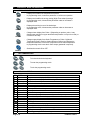
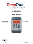
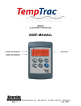
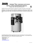
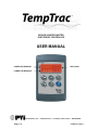
BOILER & WATER HEATER ELECTRONIC CONTROLLER USER MANUAL UPPER LED READOUT LED ICONS LOWER LED READOUT PVI Industries, LLC • 3209 Galvez Dr • Fort Worth, Texas 76111 • 800/784-8326 Page 1 / 6 PV500-40 01/25/11 1. DISPLAY AND INTERFACE 1.1 KEYBOARD BUTTONS SET - Displays and modifies the temperature set points. In programming mode, it selects a parameter or confirms an operation. - Displays and modifies the energy saving (Night Time setback) settings. In programming mode, it browses the parameter codes or increases a displayed value. - Displays the working hours of the load relays. In programming mode, it browses the parameter codes or decreases a displayed value. - Changes lower display from Probe 1 (Depending on product, probe 1 may display lower tank/inlet or upper tank/outlet temperature or may not be used.) to current time and day. - Changes upper display from Outlet Temperature to Probe 3 (Optional Temperature Probe. Used for Outdoor Reset on Boilers) and displays the temperature difference of the Inlet Temperature minus Outlet temperature. In programming mode it sets the 4-20mA output (password is required). - Switches the control ON or OFF. UP DOWN CLOCK EXT ON/OFF 1.2 1.3 LED Ext ES KEY COMBINATIONS + To lock and unlock the keyboard. + To enter the programming mode. + To exit the programming mode. LED ICON LEGEND MODE ON ON Flashing ON Flashing ON Flashing ON ON ON ON FLASHING FLASHING FLASHING ON FLASHING FLASHING ON ON Page 2 / 6 Function Temperatures are displayed in Fahrenheit degree Temperatures are displayed in Celsius degree Call for heat time delay Call for heat is on Second stage time delay (On 2-stage units only) Second stage on Freeze protection time delay Freeze protection on Modulation output signal is in manual control mode Modulation output signal is automatically controlled by temperature probe 1 The outside temperature is displayed Low gas pressure alarm High gas pressure alarm Low-water alarm Lower LED readout is displaying the clock Alarm signal Programmed working hours limit is exceeded Working hours are displayed in Lower LED readout The energy saving function is running PV500-40 01/25/11 1.4 UPPER LED READOUT The default display of this readout is the temperature sensed at Probe 2. In a Boiler, Probe 2 will be inserted into the outlet area and can control the outlet temperature. In a Water Heater, Probe 2 will be inserted into the appropriate area of the storage tank to provide effective temperature response for the heat source (this may not be at the top of the tank). By pressing and releasing the button once, the Upper LED will display the actual temperature sensed at Probe 3 (Optional Temperature Probe. Used for Outdoor Reset on Boilers). By pressing and releasing the button twice, the Upper LED will display the difference between the actual temperature sensed at Probe 2 and the temperature sensed at Probe 1 (if used). To return to the default in the Upper LED readout, wait 15 seconds after the pressed and released twice. 1.5 button is LOWER LED READOUT The default display of this readout is the temperature sensed at Probe 1. In a Boiler, Probe 1 will be inserted into the return piping of the boiler heating loop. In a Water Heater, Probe 1 (if used) will be inserted into upper area of the storage tank. By pressing and releasing the button once, the Lower LED display will show the Time of Day. Press again to return to default display. 1.6 1. TO SET THE CURRENT TIME AND DAY (MILITARY TIME) Push and hold the button for more than 3 seconds. The LED icon starts flashing and the “Hur” (hour) parameter name is displayed in the Upper LED readout, its value is displayed in the Lower LED readout. 2. Pushing the or button alternates the LED readouts between the following: “Hur” (hour) in the Upper readout and its value in the lower readout “Min” (minute) in the Upper readout, its value in the Lower readout “dAY” (day) in the Upper readout, its value in the Lower readout 3. To adjust a value, press the button and the value in the Lower LED will start flashing. Change the value by pressing the + or buttons. When correct, press . or wait 15 seconds without pressing any buttons. 4. To exit push 1.7 TO SET THE ENERGY SAVING TIME (NIGHTIME SETBACK) Contact factory for detailed TempTrac instructions. Page 3 / 6 PV500-40 01/25/11 1.8 TO SET MODULATION PARAMETERS Contact factory for detailed TempTrac instructions. 2. 2.1 PROGRAMMING SETPOINT DESCRIPTIONS AND PROGRAMMING Setpoints are those temperature or operating parameters that the user can adjust. St 1 - This setpoint temperature should be considered the °F or °C temperature threshold to activate the burner. The setpoint corresponds directly to the temperature sensed by probe 1. The St 1 setpoint is programmed as an absolute temperature; for example 160°F. St 2 - This setpoint corresponds to the threshold for second-stage burner operation. The St 2 setpoint is programmed as the number of degrees below St 1 (setpoint 1) when the second stage will activate; for instance, - 8. The St 2 setpoint is only applicable on products that have stage-fired/modulating burners. St 3 - This setpoint represents the temperature threshold for activation of freeze protection. The St 3 setpoint is programmed as an absolute temperature; for example 40°F. The St 3 setpoint is only applicable on products that have freeze protection. To program different set points proceed as described below: button, the Upper LED readout will display the “St1” parameter name, while the 1. Press the Lower LED readout will show the corresponding value. or 2. Use the parameter names. 3. Press the readout. buttons to cycle the Upper LED readout through the St 1, St 2 and St 3 button to modify a parameter value. The value starts flashing in the Lower LED 4. To change it, press the 5. Press the or buttons. button to confirm the value and pass to the setting of next set point. 6. Repeat the operations described at point 3, 4, 5. 7. To exit, push + or wait 15 seconds without pressing any button. NOTE: each point has a time out of 15 seconds. If no key is pushed within 15 seconds, the controller exits the set points programming procedure. NOTE: the set value is stored even when the procedure is exited by the 15 second expiration. Page 4 / 6 PV500-40 01/25/11 2.2 HOW TO LOCK THE KEYBOARD 1. Push and hold the UP + DOWN keys for more than 3 seconds. 2. The “POF” message will be displayed and the keyboard is locked. At this point it is only possible to view the set point. 3. Repeat step 1 to unlock the keyboard. 2.3 HOT KEY PROGRAMMING (FOR FACTORY SUPPORTED FIELD REPROGRAMMING) To upload a program from a control to a HOT KEY: + Insert HOT KEY into the TTL connection on the back of the control. Press and hold UP + DOWN keys momentarily then press the UP key. The “Upl” message will appear while uploading is occurring and the “End” message will appear when finished. Push any key to return to normal operation. To download a program from a HOT KEY to a control: ON/OFF 3. Press the ON/OFF key to turn off the control. Insert the HOT KEY into the TTL connection on the back of the control. Press the ON/OFF key again and downloading will begin. The “don” message will appear while downloading is occurring and the “End” message will appear when finished. Push any key to return to normal operation. ALARMS Alarm messages are displayed in the upper LED readout and alternate with the default display. An alarm LED icon is also illuminated. Message Cause “P1” Probe 1 failure “P2” “P3” Probe 2 failure Probe 3 failure “HA” “LA” HP LP Mn1 Mn2 Mn3 “rtc” “rtF” High temperature limit set point exceeded Low- temperature alarm High gas pressure/low water cut-off alarm Low gas pressure alarm Maintenance alert for call-for-heat Maintenance alert for second stage Maintenance alert for freeze protection The real time clock has lost the setting Real time clock failure Page 5 / 6 Results of alarm condition - Call for heat and burner second stage interrupted; modulation output signal will revert to low fire - Freeze protection is disabled - Outdoor reset disabled - Warm weather shut down disabled - Buzzer sounds, operation continues - Buzzer sounds, operation continues - Unit deenergized after time delay - Unit deenergized after time delay - Buzzer sounds, operation continues - Buzzer sounds, operation continues - Buzzer sounds, operation continues - Energy saving functions disabled - Energy saving functions disabled PV500-40 01/25/11 3.1 BUZZER The TempTrac buzzer is activated each time connected alarm condition happens. The following are representative alarm conditions that may be connected to and activate the TempTrac buzzer (some alarms may be connected to and operate separately from the TempTrac on some products). High/low water temperature alarm Probe failures High and low gas pressure Low water The buzzer is silenced by pressing any button (alarm condition still present) 3.2 ALARM RECOVERY 1. Probe failure alarm automatically ends after normal operation is re-established. Check connections before replacing the probe. 2. Temperature alarms “HA” and “LA” automatically stop as soon as probe 1 senses temperatures within normal operating parameters. 3. High and low gas pressure alarms recover when pressure is normalized and any button is pressed. (if used) 4. Low water alarm recovers when water level normalizes and any button is pressed. (if used) 5. RTC alarm stops after programming the real time clock. 6. RTF alarm requires the replacement of the real time clock. For additional information, contact the PVI Industries Customer Service Dept at 800-784-8326. Page 6 / 6 PV500-40 01/25/11