1
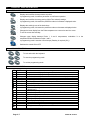
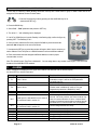
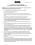
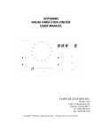
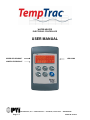
WATER HEATER ELECTRONIC CONTROLLER USER MANUAL UPPER LED READOUT LED ICONS LOWER LED READOUT PVI Industries, LLC • 3209 Galvez Dr • Fort Worth, Texas 76111 • 800-784-8326 Page 1 / 7 PV500-40 04/2013 1. DISPLAY AND INTERFACE 1.1 KEYBOARD BUTTONS - Displays and modifies the temperature set points. In programming mode, it selects a parameter or confirms an operation. - Displays and modifies the energy saving (Night Time setback) settings. In programming mode, it browses the parameter codes or increases a displayed value. - Displays the working hours of the load relays. In programming mode, it browses the parameter codes or decreases a displayed value. - Changes the lower display from the Probe temperature to current time and vice versa. To set the current time and day. - Changes upper display between Probe 1, 2 and 3 temperatures, modulation % or the temperature difference between Probe 1 and 2. In programming mode it sets the 4-20mA output (Passkey is required (321)). - Switches the control ON or OFF. SET UP DOWN CLOCK EXT ON/OFF 1.2 1.3 KEY COMBINATIONS + To lock and unlock the keyboard. + To enter the programming mode. + To exit the programming mode. LED ICON LEGEND LED Ext ES MODE ON ON Flashing ON Flashing ON Flashing ON ON ON Flashing ON FLASHING FLASHING ON FLASHING FLASHING ON ON Page 2 / 7 Function Temperatures are displayed in degrees Fahrenheit Temperatures are displayed in degrees Celsius Call for heat time delay or remote enable/disable is in standby (disabled) Call for heat is on Second stage time delay (On 2-stage units only) Second stage on or the AL2 alarm output is enabled. Output 3 time delay Output 3 relay on Modulation output signal is in manual control mode or forced to the i1S setting by digital input 1 Modulation output signal is automatically controlled by temperature probe 1 Modulation output time delay is activated. Probe 3 is displayed Digital input 2 (alarm) is activated Digital input 3 (alarm) is activated Lower display is displaying the time Alarm signal Programmed working hours limit is exceeded Working hours are displayed in Lower LED readout The energy saving function is running PV500-40 04/2013 1.4 UPPER LED READOUT The default display of this readout is the temperature sensed at Probe 2. Probe 2 may display the tank stored water temperature, outlet water temperature, flue gas temperature, ambient temperature, remote tank or blended water temperature, etc., depending on the product and application. Refer to your specific water heaters Installation and Maintenance Manual and the supplied wiring drawing. The upper LED readout can also be switched to display Probe 1 or 3 (if used) or the modulation % or the temperature difference between Probe 1 and 2. If Probe 2 is not utilized, the display will show “nu”. button once, the Upper LED will display the actual temperature sensed at By pressing and releasing the Probe 3. Probe 3 (if used) may display the flue gas temperature or outside ambient temperature, etc., depending on the product and application. By pressing and releasing the button again, the Upper LED will display the modulation % (indicated by 0 to 100%). If the product is a non-modulating product, the displayed value should not be considered. button a third time, the Upper LED will display the difference between the By pressing and releasing the temperature sensed at Probe 2 (if used) and the temperature sensed at Probe 1. To return to the default in the Upper LED readout, press the temperature. button to cycle back to the Probe 2 All of the display information described above is available for monitoring through the optional MODBUS RTU interface. 1.5 LOWER LED READOUT The default display of this readout is the temperature sensed at Probe 1. Probe 1 will be inserted into the appropriate area of the storage tank to provide effective temperature response for the heat source (this may not be at the top of the tank). Refer to your specific water heaters Installation and Maintenance Manual and the supplied wiring drawing. The lower LED readout can also be switched to display Probe 2 or 3 (if used) or the modulation % or the Time of Day. By pressing and releasing the to return to default display. 1.6 button once, the Lower LED display will show the Time of Day. Press again TO SET THE CURRENT TIME AND DAY (MILITARY TIME) 1. Push and hold the button for more than 3 seconds. The LED icon starts flashing and the “Hur” (hour) parameter name is displayed in the Upper LED readout, its value is displayed in the Lower LED readout. 2. Pushing the or button alternates the LED readouts between the following: “Hur” (hour) in the Upper readout and its value in the lower readout “Min” (minute) in the Upper readout, its value in the Lower readout “dAY” (day) in the Upper readout, its value in the Lower readout 3. To adjust a value, press the pressing the 4. To exit push or + button and the value in the Lower LED will start flashing. buttons. When correct, press Change the value by . or wait 15 seconds without pressing any buttons. Note: This device recognizes Sunday as the first day of the week and Saturday as the last. Page 3 / 7 PV500-40 04/2013 1.7 TO SET THE ENERGY SAVING TIME (NIGHTIME SETBACK) 1. Push and hold the displayed. button for more than 3 seconds and the first parameter of the energy saving will be 2. Use the buttons to browse them. or 3. To change a value, push the 4. To exit from the menu, press 1.8 button followed by and or and then the button again. or wait for 30 seconds. TO SET MODULATION PARAMETERS 1. Push and hold the button for more than 3 seconds and the LED will switch ON and a passkey will be required to view and manually change the modulation % value. Passkey is “321”. 2. Upon entering the password, the modulation % value will be displayed in the lower display. 3. To manually adjust this value, push the or buttons and then the 4. To exit from the menu, press button; the value will start flashing. Adjust it by using the button again. and together or wait for 30 seconds. 2. PROGRAMMING 2.1 SETPOINT DESCRIPTIONS AND PROGRAMMING Setpoints are those temperature or operating parameters that the user can adjust. St 1 - This setpoint temperature should be considered the °F or °C temperature threshold to activate the energy source. The setpoint corresponds directly to the temperature sensed by probe 1. The St 1 setpoint is programmed as an absolute temperature; for example 120°F. St 2 - This setpoint corresponds to either the threshold for second-stage burner operation or an ancillary devise such as a pump. The St 2 setpoint is either programmed as the number of degrees below St 1 (setpoint 1) when the second stage will activate; for instance, - 8°F OR as an independent; for instance 115°F. The St 2 setpoint is only applicable on products that have stage-fired/modulating burners or ancillary components such as circulation pumps. St 3 - This setpoint represents the temperature threshold for activation of freeze protection or flue gas temperature protection, depending on the product or application. The St 3 setpoint is programmed as an absolute temperature; for example 40°F or 150°F. The St 3 setpoint is only applicable on products that have freeze protection or require flue gas temperature protection. Page 4 / 7 PV500-40 04/2013 To program different set points proceed as described below: button, the Upper LED readout will display the “St1” parameter name, while the Lower LED 1. Press the readout will show the corresponding value. 2. Use the or buttons to cycle the Upper LED readout through the St1, St2 and St3 parameter names. On some products St2 and St3 will be located in the PR2 menu and require password access. button to modify a parameter value. The value starts flashing in the Lower LED readout. 3. Press the 4. To change it, press the or buttons. button to confirm the value and pass to the setting of next set point. 5. Press the 6. Repeat the operations described at point 3, 4, 5. 7. To exit, push + or wait 15 seconds without pressing any button. NOTE: each point has a time out of 15 seconds. If no key is pushed within 15 seconds, the controller exits the set points programming procedure. The set value is stored even when the procedure exits due to the 15 second expiration. 2.2 HOW TO LOCK THE KEYBOARD + keys for more than 3 seconds. 1. Push and hold the 2. The “POF” message will be displayed and the keyboard is locked. At this point it is only possible to view the set point. 3. Repeat step 1 to unlock the keyboard. 2.3 HOT KEY PROGRAMMING (FOR FACTORY SUPPORTED FIELD REPROGRAMMING) To upload a program from a control to a HOT KEY: Insert HOT KEY into the TTL connection on the back of the control. Press and hold + keys momentarily then press the key. The “Upl” message will appear while uploading is occurring and the “End” message will appear when finished. Push any key to return to normal operation. + To download a program from a HOT KEY to a control: Press the ON/OFF key to turn off the control. Insert the HOT KEY into the TTL connection on the back of the control. Press the key again and downloading will begin. The “don” message will appear while downloading is occurring and the “End” message will appear when finished. Push any key to return to normal operation. Page 5 / 7 PV500-40 04/2013 2.4 ASSIGNING TEMPTRAC ADDRESS FOR MODBUS-RTU The first step to interfacing a BAS (Building Automation Control) with a water heater or group of water heaters will be the assignment of the address number for each heater. 1. Enter the Programming mode by pressing the Set and DOWN key for 3s. (lead with the SET key) 2. Press the DOWN key. 3. Select “Pr2” – “PAS” parameter and press the “SET” key. 4. The value “0 - -” with a flashing zero is displayed. Adr 1 5. Use UP or DOWN keys to input the Passkey in the flashing digit; confirm the figure by pressing “SET”. The Passkey is “321“. 6. Once you have entered the Pr2 menu press the DOWN key three times and the parameter Adr will appear on the screen as follows: 7. Now press the SET key once and the number will begin to blink. Use the arrow key to set the address. Each TempTrac on a RS-485 network must have a different address 8. Each water heater should be assigned a different address in order for proper communication to occur. Note: The default for each TempTrac is Address #1. You can assign them to any number in the range of 1-247, this is the limitations of the MODBUS RTU standard. 3. ALARMS Alarm messages are displayed in the upper LED readout and alternate with the default display. An alarm LED icon is also illuminated. Message Cause “P1” Probe 1 failure “P2” Probe 2 failure “P3” Probe 3 failure “HA” “LA” High-temperature limit set point exceeded Low-temperature alarm “AL2” Digital Input 2 is activated for one or more of the conditions listed in section 3.1 “AL3” “Mn1” “Mn2” “Mn3” “rtc” “rtF” “AL1” Digital Input 3 is activated for one or more of the conditions listed in section 3.1 Maintenance alert for call-for-heat Maintenance alert for second stage Maintenance alert for freeze protection The real time clock has lost the setting Real time clock failure Digital Input 1 Alarm Page 6 / 7 Results of alarm condition Call for heat and burner second stage interrupted; modulation output % will be the PP4 parameter (generally low fire) Output 3 is open Dynamic reset of Set1 disabled. Outdoor reset is disabled (if used) or Flue gas temperature protection is disabled (if used) Audible alarm sounds, operation continues Audible alarm sounds, operation continues Unit de-energized after time delay. Audible alarm sounds. On some products, the alarm contacts may close for remote indication of alarm. Internal alarm register will communicate an alarm condition through the Modbus RTU communication link (if equipped) Unit de-energized after time delay. Audible alarm sounds, operation continues Audible alarm sounds, operation continues Audible alarm sounds, operation continues Energy saving functions disabled Energy saving functions disabled Output 1 open. PV500-40 04/2013 3.1 AUDIBLE ALARM The TempTrac audible alarm is activated each time a connected alarm condition occurs. The following are representative alarm conditions that may be connected to and activate the TempTrac audible alarm (some alarms may be connected to and operate separately from the TempTrac on some products). High/low water temperature alarm Probe failures External thermostat limit failure Flame Failure High and low gas pressure Low water The audible alarm is silenced by pressing any button (alarm condition still present) 3.2 ALARM RECOVERY 1. Probe failure alarm automatically ends after normal operation is re-established. Check connections before replacing the probe. 2. Temperature alarms “HA” and “LA” automatically stop as soon as probe 1 senses temperatures within normal operating parameters. 3. Digital input 2 & 3 alarms recover when condition(s) listed above are normalized and any button is pressed (if used). Resetting the alarm condition may require resetting individual safety devices or cycling main power switch. 4. RTC alarm stops after programming the real time clock. 5. RTF alarm requires the replacement of the real time clock. For additional information, contact the PVI Industries Customer Service Dept at 800-784-8326. Page 7 / 7 PV500-40 04/2013