1
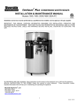
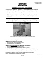
Form number: 34-400.5
Issue Date: 12/05/07
Installation Instructions - Supplemental
Connecting PRIMERA® boilers to a Boiler Management System
Installation of Boiler Management System must be performed by a qualified service installer or
service agency. These instructions are to supplement the Installation and Maintenance Manual
provided with your Primera water heater or boiler.
Before you begin, read and follow these instructions, as well as the information contained in
the Primera Installation and Maintenance Manual. To obtain an additional copy of the Primera
Installation and Maintenance Manual, or for any questions, call Riverside Hydronics, LLC at
1-800-990-5918.
WARNING: If the information in the supplied instructions and manual(s) is not
followed exactly, a fire, explosion or exposure to hazardous materials may
result, causing property damage, personal injury or loss of life.
Connections for BMS control are made to the terminal strip located on rear of PRIMERA control box.
The terminal strip is accessed by removing the PRIMERA top pan.
Refer to above picture for all applications
If BMS is to provide remote on/off control only:
1. Remove the jumper connecting terminals R1 and R2
2. Connect the BMS output leads for the enable/disable function to terminals R1 and R2
3. Leave all other wires in their initial positions
If BMS provides STAGE-FIRING control: (Models 400B, 750B and 1000B)
1. Remove the jumper connecting terminals R1 and R2
2. Connect the BMS first stage leads to terminals R1 and R2 (no polarity)
3. Connect the BMS second stage leads to terminals T1 and T2 (no polarity)
4. On the TempTrac Control, move parameter St1 up to its maximum setting of 180°F. This setting
effectively takes the TempTrac out of the way and allows complete control by the BMS system
5. Leave all other wires in their initial positions
NOTE: BMS must call for both first and second stage operation before firing cycle will be
initiated. Afterward, BMS can cycle between low and high fire.
PN: 105179
Page 1 of 2
Form number: 34-400.5
Issue Date: 12/05/07
If BMS provides MODULATION control through a 4 to 20 milliamp or 0 to 10 volt signal:
1. Remove the jumper connecting terminals R1 and R2
2. Connect the BMS output leads for the enable/disable function to terminals R1 and R2 (no polarity)
3. Remove blue wire from terminal T1 and cap the end with a wire nut. Secure the loose wire.
4. Connect the BMS variable signal output leads to terminals T1 and T2 (T1 is positive, T2 is negative)
5. On the TempTrac Control, move parameter St1 up to its maximum setting of 180°F. This setting
effectively takes the TempTrac out of the way and allows complete control by the BMS system.
6. If the BMS supplies a 0 to 10 volt signal, remove the resistor connecting terminals 1 and 3. For milliamp
signal, resistor must remain in place
7. Leave all other wires in their initial positions
In all cases, the BMS must sense temperature on the building’s hydronic distribution loop upstream of the
PRIMERA boilers. No attempt should be made to control the PRIMERA boilers by sensing temperature
downstream of the boilers.
PN: 105179
Page 2 of 2