1
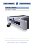
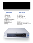
MultiWave II+ Installation
Instructions
P300, P600, P1200
You MUST have MWII
installed prior to adding the
Plus software
What’s in the Box
Table of Contents
•
•
•
•
•
•
•
1....What’s in the Box
2....Warning
2....Safety Instructions
2....Overview
3....Installing the Upgrade
6....Testing the Power Plant
6....MultiWave II+ Operation
7....MultiWave II+ Waveforms
8....Warranty and Service Issues
8....Contact Information
1
One
One
One
One
One
One
One
display microchip
MWII card microchip
chip puller
plastic dentist mirror
anti-static wrist strap
instruction booklet
MultiWave II+ silver sticker
fans should not be used with MultiWave II+
unless it is in the sine wave mode. This
equipment must be used with sin mode.
Warning
To prevent fire or shock hazard, do not
expose the MultiWave II+ kit to rain or
moisture. To avoid electrical shock, the
Power Plant must be unplugged and fully
discharged before opening.
We recommend the use of the Sine Wave
[sin], or TubeWave™ [tub] with any type of
tube based audio products.
Overview
To prevent electric shock, use a 3 prong,
grounded type power cable.
Read the entire instruction manual
before starting the installation.
Any change or modifications not expressly
approved in the manual could void your
warranty.
The benefits the Plus upgrade kit will provide for your MultiWave II equiped power
plant are:
Safety Instructions
• Fine tuning for turntables
• Clean Sweep
General Instruction:
Read the operating instructions provided
with your MultiWave II+ kit.
The MultiWave II+ upgrade is a fairly simple
process. If you have any questions at any
time, please contact your dealer, distributor
or PS Audio by e-mail, fax or telephone at
the numbers listed at the end of the instructions.
If the Power Plant is powered on with the
oscillator card inserted backwards, the
Power Plant will require service from an
authorized PS Audio dealer.
The overview steps necessary to install
MultiWave II+:
Retain the operating instructions for later
use and reference
Make sure your unit already has been
upgraded to MultiWave II! You cannot install the Plus upgrade without
MultiWave II installed first.
Completely discharge the Power Plant
before opening the chassis by unplugging
the unit for at least 12 hours.
Unplug the Power Plant from the wall outlet
before changing the fuse or performing any
upgrade or service.
1. Remove the input power cable from the
rear of the power plant.
2. On the P300, remove the bottom cover.
On the P600/P1200, remove the top
cover.
3. Pull the socketed MW II oscillator board
out.
4. Replace the microchip on the MultiWave
II oscillator board.
5. Remove display microchip.
6. Install new display microchip.
7. Insert the oscillator board with its new
chip, back into the unit.
8. Replace the bottom cover or the top
cover, depending on your model.
9. You are done.
Do not operate the Power Plant near water.
Avoid placement near a water reservoir or
excessive moisture.
When replacement parts are required, be
sure they are specified by the manufacturer
to have the same characteristics as the original. Unauthorized substitutions may result
in fire, electric shock, or other hazards.
Do not operate with faulty or frayed power
cables.
MultiWave II+™ operation:
Any turntable or equipment with AC
synchronous motors, such as some cooling
2
and set it aside.
Installing the Upgrade
If your P300 has a fan kit there will be a
wire connecting the bottom plate to the
inside of the chassis. Trace the wire back to
the bottom circuit board and
remove
the
connector by
pressing in on
the side clips
and gently pulling the connector out of the
plug labeled J9. Set the bottom plate aside.
Before beginning the Plus upgrade, you will
need to do the following:
The Night Before
Unplug the Power Plant the night before (or
at least several hours before) you plan to do
the upgrade. Really unplug it! Take out the
input power cable and take out all the power
cables connecting to your a/v equipment. By
letting the Power Plant sit overnight, most of
the energy stored in the power supply will
drain away.
The Day of the Upgrade
Assemble the following tools in your work
area:
• A clean table to place the Power Plant
while you are working.
• For the P300 - a #2 Phillips head screwdriver. For the P600/P1200 - A 7/64” Allen
wrench.
• A desk lamp, gooseneck lamp or other light
placed next to the Power Plant so you can
see what you are doing.
• The MultiWave II+ Upgrade Kit.
Disassembly - P600/P1200
Keep the P600/P1200 upright so you have
easy access to the top. Use an Allen wrench
to remove the Allen screws affixing the top
cover of the P600/P1200. Remove the top
cover and set it aside.
Removing the old oscillator card - P300
Grab the card by the edges and lift straight
up to remove. Do not rock the card back
and forth to remove it! Set it aside. NOTE
THE CARD’S ORIENTATION. ITS PARTS
FACE TOWARDS THE FRONT PANEL.
YOU MUST PUT THIS CARD BACK IN
EXCATLY THE SAME WAY!
Before opening the Power Plant
• Ensure it is fully unplugged and discharged for at least several hours or
more.
Removing the old oscillator card P600/1200
Do not remove
the screws that
attach the oscillator card to the
motherboard
(bottom circuit
board). Remove
the two screws
and nuts holding
the oscillator board to the L-brackets.
Disassembly - P300
Turn the P300 upside down, with the feet
facing up. Use the screwdriver to take out
the 10 small screws holding on the bottom
plate of the P300. Note: You do not need to
remove the screws holding down the feet to
the bottom cover of the P300.
After you take off the ten screws from the
bottom cover, carefully and slowly lift the
bottom cover straight off. You may notice
some slight resistance. The oscillator card
in the P300 is secured by a small gray
plastic bracket on the inside of the bottom
cover. Note: some P300’s may not have this
plastic bracket.
Grab the card by the edges and lift straight
up to remove. Do not rock the card back and
forth to remove it! Set it aside.
Removing the
old front panel
display microchip
First locate the
front panel display board. This
Usually, the oscillator card will stay plugged
into the P300 main board. Sometimes, the
oscillator card gets unplugged from the
main board and instead stays attached to
the gray plastic support. If this is the case,
simply remove the card from the support
3
is the circuit board that is screwed to the
Power Plant’s front panel.
safety and orientation as you just did on the
first chip installation.
out of the way.
Great work. You
are almost done.
Take a break.
Take this time to
attach the antistatic wrist strap
to your wrist by
wrapping
the
clear sticky end
around your wrist like a bracelet. Remove
the adhesive strip from the copper tail and
attach it to an exposed aluminium surface
inside the Power Plant chassis.
Locate the chip
puller enclosed
with
the
MultiWave II+
package. The
chip puller will
be used to carefully remove the
old microchip.
Notice the chip puller has
two small prongs. Put the
two prongs of the chip puller between the
chip and the socket on the left and right side.
There is a small gap between the chip and
the socket for you to insert the prongs of the
chip puller. It may take a little wiggling of the
chip puller to get its prongs under the chip.
Installing the new front panel display
microchip AND MWII card microchip
Carefully open the sealed end of the silver anti-static bag marked FRONT PANEL
DISPLAY (you are wearing your wrist strap
now, aren’t you?). Carefully remove the new
processor chip from the silver bag. The chip
is pressed to a small piece of black foam.
This special foam protects the chip from
static. Do not remove the chip from the
antistatic foam at this time.
Squeeze the chip puller together and pull
the microchip straight out of its socket. It
may take a tug. Pull straight back. When the
old microchip pops out of its socket, lay it
out of the way.
Removing the old MWII microchip from
the board you removed
First locate the MWII board you removed
from the Power Plant.
Notice that the chip has a “half moon” on
one side. There is also a white dot to help
identify the direction. Looking from the rear
of the unit, this
dot must face to
the RIGHT on
the P600/P1200
and the LEFT
on the P300.
Note:
Some
P600 models
may have the
display microchip aligned vertically with the
half moon and white dot facing UP.
Using the same technique you used for
removing the front panel display chip, locate
the same looking chip on the separate MWII
board. Note the small half moon and
white dot and
how it is oriented in the socket.
You will need to
put the new chip
in exactly the
same way. Put
the two prongs
of the chip puller
between the chip and the socket on the left
and right side. There is a small gap between
the chip and the socket for you to insert the
prongs of the chip puller. It may take a little
wiggling of the chip puller to get its prongs
under the chip.
Now, carefully use your fingers to pull the
chip straight out of the black protective
foam. Yep, you can use the chip puller for
this if you like. The key is pulling the chip
straight out of the foam so that we do not
bend any of the little legs.
After you pull the chip out of the foam, lay
it so it rests on its legs on top of the black
foam. It will look a lot like a bug - a healthy
bug with straight legs. If any of the legs are
not straight, use a finger nail to straighten
it.
Squeeze the chip puller together and pull
the microchip straight out of its socket. It
may take a tug. Pull straight back. When the
old microchip pops out of its socket, lay it
4
Do not rush
the next step.
Please
read
this next section
again before
you go on. Do
you have a light
shining inside
the Power Plant? Is it well lit? Do you have
your reading glasses on? Just checking.
Re-Installing the MWII oscillator board
Read this entire section before you
attempt to replace the oscillator board.
Now take the oscillator board in your hand.
Be careful to only touch the edges of the
board. Notice the printed warning on the
top of the board
indicating which
side of the board
must face the
front panel. The
new board must
only be inserted
in the correct
direction.
You are going
to next insert
the chip into
the socket. Do
this by grasping
the small sides
of the chip with
your thumb and
forefinger. Now, carefully line up the legs
of the chip with the holes in the socket. BE
VERY CAREFUL. Only lightly press the chip
into the socket at this time - just enough for
the socket to hold the chip. You just want to
get the legs started. Do not press hard on
the chip at this time.
The electronic components on the oscillator
board must face forward, toward the faceplate of the Power Plant. Never insert the
oscillator board so that the electronic components face to the rear of the Power Plant.
Insert the oscillator board into its socket on
the Power Plant’s main board by pushing
straight down. Do not rock the card back
and forth.
Insert
it
straight.
The board
must not be
inserted at
an angle.
Now make sure each leg of the microchip
is inserted in the corresponding socket
hole. That’s what the little dentist’s mirror
is for. You should be able to see the pins
on the top of the socket with your eye. The
dentist mirror will help with the lower set of
pins. Most problems of MultiWave installation have been found to be people’s failure
to get the bottom row of legs in the socket
properly. Make double sure.
If you are
working on
a P600 or
a
P1200,
replace the
two small screws and nuts that hold the
oscillator board in place.
When you are sure that each leg of the
microchip is straight and lined up correctly,
top and bottom rows, press the microchip
down into the socket. The chip will seat
almost flush into the socket.
Inspect your work
You are almost done!
Now, use the mirror again to inspect the
microchip and socket. The microchip must
be flush in the socket and no pins should be
bent or coming out of the socket.
Carefully inspect you work one more time
before you button up. The items you want
to check will be:
Install the new chip on the MWII oscillator card
Next, find the second silver anti-static bag
marked OSCILLATOR and replace the chip
on the MWII separate board with this new
one, following the same instructions for
• The new microchip on the front panel
display board is inserted correctly. Use that
mirror if you need to!
5
The Power Plant front panel should indicate [Sin] If it does, the Power Plant is fully
operational and you are now a certified
PS Audio MultiWave II+ upgrade installer.
We are proud of you, but you may want to
keep your day job.
• The oscillator board is fully inserted with
the electronic components facing the front
of the Power Plant.
• If the Power Plant is powered on with
the oscillator card inserted backwards,
the Power Plant will require service from
an authorized PS Audio dealer.
• Don’t forget to remove the anti-static wrist
strap before leaving you work area.
Replace the bottom cover - P300
If your P300 has a fan, reattach the fan wire
to the main board. It should be reconnected
to plug J9. The connector will only fit on in
one direction as the plugs are U-shaped.
YOU’RE DONE! Really. But keep that dentist mirror close by. Who knows what microchips or teeth might need inspecting.
Before reinstalling the bottom cover of the
P300, notice the gray support strip on the
inside of the bottom cover. The groove in
this support strip aligns with the edge of the
oscillator board. Replace the bottom cover
of the P300. Align the top of the oscillator
board with the groove in the gray support
strip. When they are aligned, press down
on the bottom cover. It will snap into place
when properly aligned. Sorry, the trusty dentists mirror will not help you here.
NOW, hold on to your favorite listening chair
and experience MultiWave II+. We are quite
sure you will be as amazed as we were the
first time we listened. Use Clean Sweep
and do a full system clean after everything’s turned on and ready to go.
Its benefitrs become addicting after a while
so Clean Sweep the system before every
serious listening session.
If you have any questions about the installation process, stop and contact us. We are
here to help.
In the case of the support strip not being
attached to the bottom cover, simply attach
the support strip to the top edge of the
oscillator card before replacing the bottom
cover.
MultiWave II+ Operation
Notice of MultiWave II+ operation:
Any turntable or equipment with AC
synchronous motors, such as some cooling
fans should not be used with MultiWave
patterns. This type of equipment must be
used with 60Hz sin mode.
Replace the screws in the bottom cover.
Replace the top cover - P600/P1200
Line the top cover up against the front bezel
of the Power Plant. This should help in lining
up the Allen screw holes.
We recommend the use of the sine wave
[sin], or TubeWave™ [tub] with any type of
tube based audio products.
Replace the Allen screws in the top cover.
Place the MultiWave II+ sticker on the
back of your Power Plant
There are five available display modes on
the front panel of the Power Plant. The
Mode button will cycle through the following
five modes:
Testing the Power Plant
To make sure everything is tip-top, perform
the following tests:
1.
2.
3.
4.
5.
6.
• Plug the Power Plant into a power source.
Do not plug anything into the back of the unit
at this time.
• If you have a P300 ensure the back panel
switch is on. Up is ON.
• Next, press the front panel power switch.
Waveform setting
Frequency generated (sin mode only)
Voltage produced
Wattage produced
Display blanking mode
Clean Sweep
Waveform setting
This mode will display the name of the
6
waveform presently being generated.
For more information about each of the
MultiWave settings, see the MultiWave II+
Waveforms section of the manual.
accurately on the Power Plant's meter. For
true power consumption figures consult the
owners manual of the connected product.
Under normal operation a green LED will
illuminate. A yellow LED will indicate a
heavy load and is not recommeded for
continous operation. A red LED indicates an
overload or fault mode.
Frequency generated
The frequency setting will only be displayed
if the Waveform menu is set to Sin.
This mode will display the frequency the
Power Plant is generating. The frequency
can be adjusted in 1 hertz increments from
50Hz to 120Hz by using the Up and Down
buttons. The default setting is 60Hz.
Display Blanking
This mode allows discrete front panel
operation by blanking the display. The PS
logo will continue to illuminate in blue to
indicate that the unit is operational.
New with MultiWave II+ is the ability to fine
tune the frequency which is particularly
useful with turntables.
Clean Sweep
Clean Sweep is a revolutionary new feature
of the Power Plant that, in effect, cleans
and demagnetizes the power supplies and
power cables of all connected equipment.
Frequency Fine Tuning Turntables
1) After selecting the desired frequency,
press the Mode Up Button. This will take
you to the frequency fine tuning menu.
We recommend running this feature before
every serious listening session. There is a
60 second Clean Sweep mode, which is to
be used for initial cleaning before listening.
There is a Quick Sweep mode that will clean
for 5 seconds and is designed for use as a
touch up cleaning action when needed.
2) You can go up or down in 0.0625Hz steps
up to a full +/- 1hz of range. The display
will read -16 to 0 to 16. Each step is
0.0625Hz.
3) If you change the main frequency, the fine
tuning value will be cleared.
1) Press the Mode Up Or Mode Down
Button until the word CLEAN appears on
the display.
Voltage produced
This mode will display the output voltage of
the Power Plant. Note: the voltage figure
will be flashing. The output voltage can be
adjusted in 1 volt increments by using the
Up and Down buttons. The range varies
depending on the Power Plant model:
2) For a full system cleaning process (60
seconds), press the edit down button.
3) For a quick clean (5 seconds), press the
edit up button.
• 100 volt model ranges from 95 - 105 v.
Default setting is 100 volts.
• 120 volt model ranges from 100 - 120 v.
Default setting is 117 volts.
• 240 volt model ranges from 220 - 240 v.
Default setting is 240 volts.
(adjustments in 2 volt increments)
As long as the voltage to the Power Plant
does not deviate more than 10% below
normal it will continue to output the voltage
displayed on the front panel.
4) The cleaning process is complete once
the countdown stops and the world
CLEAN is displayed on the display.
MultiWave II+ Waveforms
[sin] sine wave
In the sine wave mode the Power Plant will
generate a perfect sine wave (50-120Hz).
[tub] TubeWave
TubeWave is specifically designed to optimize the performance of tube based audio
products.
Wattage produced
This mode will display, in real-time, the
approximate wattage the Power Plant is
generating. Complex loads may not register
7
TubeWave uses the same pseudorandom
generation of frequencies as MultiWave2
waveform, however it generates more tubefriendly frequencies.
[P-1] MultiWave1
MultiWave1 is a single 60Hz sine wave with
a minute amount of 3rd Harmonic sine waves
mixed together to form a single partial square
MultiWave. This is an improved version of PS2
from the original MultiWave™ series.
The partial square wave setting improves the
power supply’s ability to charge the capacitors
in equipment by extending the length of time
available to "top off" the capacitors' voltage.
Use this setting to enhance the performance
of both source and power equipment.
[P-2] MultiWave2
MultiWave2 is a 60Hz sine wave that
incorporates a pseudorandom collection of
frequencies which are dithered from 55-65Hz.
Using this slightly random frequency deviation
is similar to adding dither on a digital audio
source. Power supply dithering can lower
the perceived noise floor and help remove
apparent glare on the audio signal.
[P-3] MultiWave3
MultiWave3 is a combination of Multiwave1
with a slight degree of 3rd harmonic addition
(MultiWave1).
Try this setting and see how the audio sounds
and the video looks. All systems can respond
differently to each MultiWave pattern.
[P-4] MultiWave4
MultiWave4 is full combination of MultiWave1
and MultiWave2. It generates a pseudorandom
collection of frequencies, however instead of
generating sine waves it generates the same
waveform as MultiWave1.
Again, try these setting on your system to see
which one has the highest perceived benefit in
terms of performance.
8
Warranty inside the U.S. and
Canada
PS Audio’s warranty is 3 years parts and labor,
from the date of original purchase. This means
that we warranty the product itself regardless
of ownership, new or used.
Warranty outside the U.S. and
Canada
PS Audio has authorized distribution in many
countries of the world. In each country, the
authorized importing retailer or distributor has
accepted the responsibility for warranty of
products sold by that retailer or distributor.
Warranty service should normally be obtained
from the importing retailer or distributor from
whom you purchased the product. In the
unlikely event of service required beyond the
capability of the importer, PS Audio will fulfill
the conditions of the warranty. Such product
must be returned at the owner’s expense to
the PS Audio factory. Contact your PS Audio
distributor or the PS Audio customer service
department for more information.
Service issues
Should your unit ever require service or if
you have any technical questions about the
MultiWave II++ kit, you must either contact
your dealer (PS Audio if purchased direct) or
your PS Audio distributor. No equipment will
be received at our service facilities without an
attached RA number.
If purchased through an authorized PS Audio
dealer or distributor, the RA number must be
obtained by the dealer or distributor. If the
product was purchased from PS Audio direct,
this can easily be obtained by contacting PS
Audio at:
E-mail - [email protected]
Phone - 720.406.8946
Fax - 720.406.8967
http://www.psaudio.com