1
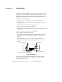
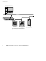
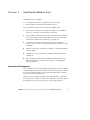
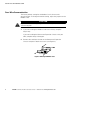
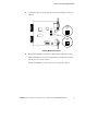
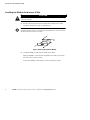
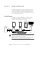
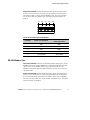
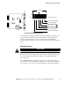
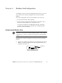
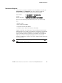
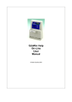
Powerware® Modbus ® Card
User’s Guide
Class A EMC Statements
FCC Part 15
NOTE This equipment has been tested and found to comply with the limits for a Class A digital device, pursuant to
part 15 of the FCC Rules. These limits are designed to provide reasonable protection against harmful interference
when the equipment is operated in a commercial environment. This equipment generates, uses, and can radiate
radio frequency energy and, if not installed and used in accordance with the instruction manual, may cause harmful
interference to radio communications. Operation of this equipment in a residential area is likely to cause harmful
interference in which case the user will be required to correct the interference at his own expense.
ICES-003
This Class A Interference Causing Equipment meets all requirements of the Canadian Interference Causing
Equipment Regulations ICES-003.
Cet appareil numérique de la classe A respecte toutes les exigences du Reglement sur le matériel brouilleur du
Canada.
EN 50091-2
Some configurations are classified under EN 50091-2 as “Class-A UPS for Unrestricted Sales Distribution.” For
these configurations, the following applies:
WARNING This is a Class A-UPS Product. In a domestic environment, this product may cause radio interference, in
which case, the user may be required to take additional measures.
Requesting a Declaration of Conformity
Units that are labeled with a CE mark comply with the following harmonized standards and EU directives:
S
Harmonized Standards: EN 50091-1-1 and EN 50091-2; EC 60950 Third Edition
S
EU Directives:
73/23/EEC, Council Directive on equipment designed for use within certain voltage limits
93/68/EEC, Amending Directive 73/23/EEC
89/336/EEC, Council Directive relating to electromagnetic compatibility
92/31/EEC, Amending Directive 89/336/EEC relating to EMC
The EC Declaration of Conformity is available upon request for products with a CE mark. For copies of the EC
Declaration of Conformity, contact:
Eaton Power Quality Oy
Koskelontie 13
FIN-02920 Espoo
Finland
Phone: +358-9-452 661
Fax: +358-9-452 665 68
Eaton, Powerware, and X-Slot are registered trademarks of Eaton Corporation or its subsidiaries and affiliates.
Modbus is a registered trademark of Schneider Electric. Wonderware is a registered trademark of Wonderware
Corporation. HyperTerminal is a registered trademark of Hilgraeve. Microsoft and Windows are registered
trademarks of Microsoft Corporation.
ECopyright 2002–2008 Eaton Corporation, Raleigh, NC, USA. All rights reserved. No part of this document may be
reproduced in any way without the express written approval of Eaton Corporation.
Table of Contents
1
Introduction . . . . . . . . . . . . . . . . . . . . . . . . . . . . . . . . . . . . . . . . . . . . . . . . . . . . . . . . .
1
2
Installing the Modbus Card . . . . . . . . . . . . . . . . . . . . . . . . . . . . . . . . . . . . . . . . . . . . .
3
Inspecting the Equipment . . . . . . . . . . . . . . . . . . . . . . . . . . . . . . . . . . . . . . . . . . . . . . . . . . . . . . . . . . . . . . . .
Four-Wire Communication . . . . . . . . . . . . . . . . . . . . . . . . . . . . . . . . . . . . . . . . . . . . . . . . . . . . . . . . . . . . . . .
Installing the Modbus Card into an X-Slot . . . . . . . . . . . . . . . . . . . . . . . . . . . . . . . . . . . . . . . . . . . . . . . . . . . .
3
4
6
Wiring the Modbus Card . . . . . . . . . . . . . . . . . . . . . . . . . . . . . . . . . . . . . . . . . . . . . . .
7
Two-Wire Networks . . . . . . . . . . . . . . . . . . . . . . . . . . . . . . . . . . . . . . . . . . . . . . . . . . . . . . . . . . . . . . . . . . .
Four-Wire Networks . . . . . . . . . . . . . . . . . . . . . . . . . . . . . . . . . . . . . . . . . . . . . . . . . . . . . . . . . . . . . . . . . . .
RS-485 Terminal Strip . . . . . . . . . . . . . . . . . . . . . . . . . . . . . . . . . . . . . . . . . . . . . . . . . . . . . . . . . . . . . . . . . .
RS-485 Modbus Port . . . . . . . . . . . . . . . . . . . . . . . . . . . . . . . . . . . . . . . . . . . . . . . . . . . . . . . . . . . . . . . . . . .
Termination . . . . . . . . . . . . . . . . . . . . . . . . . . . . . . . . . . . . . . . . . . . . . . . . . . . . . . . . . . . . . . . . . . . . . . . . .
Biasing Resistors . . . . . . . . . . . . . . . . . . . . . . . . . . . . . . . . . . . . . . . . . . . . . . . . . . . . . . . . . . . . . . . . . . .
RS-232 Modbus Port . . . . . . . . . . . . . . . . . . . . . . . . . . . . . . . . . . . . . . . . . . . . . . . . . . . . . . . . . . . . . . . . . . .
7
8
8
9
10
11
12
Modbus Card Configuration . . . . . . . . . . . . . . . . . . . . . . . . . . . . . . . . . . . . . . . . . . . . .
13
Configuring the Modbus Card . . . . . . . . . . . . . . . . . . . . . . . . . . . . . . . . . . . . . . . . . . . . . . . . . . . . . . . . . . . . .
13
Integrating the UPS . . . . . . . . . . . . . . . . . . . . . . . . . . . . . . . . . . . . . . . . . . . . . . . . . . .
17
Generating Modbus Data . . . . . . . . . . . . . . . . . . . . . . . . . . . . . . . . . . . . . . . . . . . . . . . . . . . . . . . . . . . . . . . .
Example Modbus Profiler Output Files . . . . . . . . . . . . . . . . . . . . . . . . . . . . . . . . . . . . . . . . . . . . . . . . . . . . . . .
17
18
Troubleshooting . . . . . . . . . . . . . . . . . . . . . . . . . . . . . . . . . . . . . . . . . . . . . . . . . . . . . .
23
Service and Support . . . . . . . . . . . . . . . . . . . . . . . . . . . . . . . . . . . . . . . . . . . . . . . . . . . . . . . . . . . . . . . . . . .
25
3
4
5
6
EATON Powerware® Modbus® Card User’s Guide S 164201376 Rev C www.powerware.com
i
TABLE OF CONTENTS
ii
EATON Powerware® Modbus® Card User’s Guide S 164201376 Rev C www.powerware.com
Chapter 1
Introduction
The Eaton® Powerware® Modbus® Card is an X-Slot® connectivity device
that allows you to continuously and reliably monitor the UPSs in your
Building Management System (BMS). The card uses the Modbus
protocol to integrate data from the UPS into your building management
software, such as WonderwareR.
The Modbus Card, shown in Figure 1, has the following features:
S RS-485 communication through an isolated DB-9 port or isolated
terminal strip
S Selectable termination and polarity resistance
S RS-232 communication through a DB-9 port
S Supports Modbus READ INPUT STATUS and READ INPUT REGISTER
commands
S Two-wire or four-wire communication topology
S LEDs showing communication activity
S The Modbus Profiler tool can generate a Modbus register map for
easy integration into your building management software (see
page 17)
S X-Slot design for UPSs with an internal X-Slot or installed in a
Powerware Expansion Chassis for UPSs that do not have internal
X-Slots
Communication LEDs
Configuration Port
RS-485 Modbus
(use either the DB-9 port or terminal strip)
RS-232 Modbus DB-9 Port
Figure 1. The Modbus Card
Figure 2 shows a Powerware UPS added to an existing network by
connecting the terminal strip on the Modbus Card to the RS-485
terminals on another device.
EATON Powerware® Modbus® Card User’s Guide S 164201376 Rev C www.powerware.com
1
INTRODUCTION
Building Management Software
Ethernet
Ethernet Gateway
RS-485 Network
-270.6
-270.6
Power Meter
PLC
UPS with Modbus Card
Figure 2. UPS Integrated with RS-485 Network
2
EATON Powerware® Modbus® Card User’s Guide S 164201376 Rev C www.powerware.com
Chapter 2
Installing the Modbus Card
The Modbus Card is available:
S as a separate card for use with UPSs that have an X-Slot
S factory-installed in a Powerware Expansion Chassis
Use the following sequence for installing the Modbus Card:
1.
For four-wire networks only, change the jumpers on the Modbus
Card (see “Four-Wire Communication” on page 4).
2.
If the Modbus Card will be the last device installed in the network
chain or the length of the network cable is excessive, termination
needs to be enabled (see “Termination” on page 10).
3.
Install the card with the UPS (see the Powerware Expansion
Chassis User’s Guide or “Installing the Modbus Card into an X-Slot”
on page 6).
4.
Wire the card to your network (see Chapter 3, “Wiring the Modbus
Card” on page 7).
5.
Configure the card (see Chapter 4, “Modbus Card Configuration”
on page 13).
6.
Run the Modbus Profiler tool to integrate the UPS data with the
building management software (see Chapter 5, “Integrating the
UPS” on page 17).
Inspecting the Equipment
If any equipment has been damaged during shipment, keep the shipping
cartons and packing materials for the carrier or place of purchase and file
a claim for shipping damage. If you discover damage after acceptance,
file a claim for concealed damage.
To file a claim for shipping damage or concealed damage: 1) File with
the carrier within 15 days of receipt of the equipment; 2) Send a copy of
the damage claim within 15 days to your service representative.
EATON Powerware® Modbus® Card User’s Guide S 164201376 Rev C www.powerware.com
3
INSTALLING THE MODBUS CARD
Four-Wire Communication
The factory-default setting for the Modbus Card is for two-wire
communication. To change the default setting, adjust the jumpers on the
Modbus Card.
CAUTION
To prevent electrostatic discharge (ESD), place one hand on an unpainted metal surface such
as the UPS rear panel.
1.
If you are installing the Modbus Card into an X-Slot, complete
Step 3 only.
If you are installing the Powerware Expansion Chassis with your
UPS, complete Steps 2 through 4.
2.
Remove the card from the slot on the Powerware Expansion
Chassis rear panel. Retain the screws (see Figure 3).
Figure 3. Removing the Modbus Card
4
EATON Powerware® Modbus® Card User’s Guide S 164201376 Rev C www.powerware.com
INSTALLING THE MODBUS CARD
3.
Change the J9 and J10 jumpers to the desired setting as shown in
Figure 4.
Two-Wire
(Default)
J10
J7 J8
1
J10
1
J9
J9
1 ON
S2
1234 56
Four-Wire
J10
J11
1
1
J9
Figure 4. Modbus Card Jumpers
4.
Reinstall the Modbus Card into the Powerware Expansion Chassis.
Align the Modbus Card with the slot guides and slide the card into
the slot until it is firmly seated.
Secure the Modbus Card with the screws removed in Step 2.
EATON Powerware® Modbus® Card User’s Guide S 164201376 Rev C www.powerware.com
5
INSTALLING THE MODBUS CARD
Installing the Modbus Card into an X-Slot
CAUTION
To prevent electrostatic discharge (ESD), place one hand on an unpainted metal surface such
as the UPS rear panel.
1.
Remove the X-Slot cover (or existing X-Slot module) on the UPS
rear panel. Retain the screws (see Figure 5).
NOTE Some UPSs may have another X-Slot module already installed (such as the
Powerware 9125 UPS). If there is a communication cable attached to this module, disconnect
the cable and then remove the X-Slot module.
Figure 5. Removing the Single-Port Module
2.
Install the Modbus Card into the X-Slot on the UPS.
Align the Modbus Card with the slot guides and slide the card into
the slot until it is firmly seated.
Secure the Modbus Card with the screws removed in Step 1.
6
EATON Powerware® Modbus® Card User’s Guide S 164201376 Rev C www.powerware.com
Chapter 3
Wiring the Modbus Card
The Modbus Card provides an easy path for integrating a Powerware
UPS into an RS-485 Modbus network and also provides isolation of the
communication between the UPS and the RS-485 Modbus network.
You can use the DB-9 port or terminal strip on the Modbus Card to wire
into a two-wire or four-wire network.
Two-Wire Networks
The Modbus Card’s default configuration is for two-wire, half-duplex,
RS-485 networks. Figure 6 shows a detailed view of two-wire
connections using the Modbus Card terminal strip.
Slave Device #1
Slave Device #2
UPS with
Modbus Card
RxD+
RxD–
R *
T
T-- R-- T+ R+ Gnd
T-- R-- T+ R+ Gnd
Master Device
R *
T
T-R-T+
R+
Gnd
*See Note
Figure 6. Two-Wire RS-485 Modbus Network
NOTE Only one transmission pair is used. It is not necessary to jumper the unused pair
together (this connection is made internally). Belden 9841 or equivalent cabling (a single
twisted-pair shielded cable with ground) is recommended.
NOTE If the Modbus Card is the last device installed in the network chain or the length of
the network cable is excessive, termination needs to be enabled (see page 10).
EATON Powerware® Modbus® Card User’s Guide S 164201376 Rev C www.powerware.com
7
WIRING THE MODBUS CARD
Four-Wire Networks
The Modbus Card also supports four-wire, half-duplex, RS-485 networks.
Figure 7 shows a detailed view of four-wire connections using the
Modbus Card terminal strip.
Slave Device #1
Slave Device #2
UPS with
Modbus Card
TxD+ RxD+ TxD– RxD–
R *
T
Gnd R+ T+ R-- T--
Master Device
Gnd R+ T+ R-- T--
R *
T
R *
T
T-R-T+
R+
Gnd
R *
T
*See Note
Figure 7. Four-Wire RS-485 Modbus Network
NOTE Belden 9842 or equivalent cabling (a dual twisted-pair shielded cable with ground)
is recommended.
NOTE If the Modbus Card is the last device installed in the network chain or the length of
the network cable is excessive, termination needs to be enabled (see page 10).
RS-485 Terminal Strip
The RS-485 five-position terminal strip provides an alternate interface to
attach the RS-485 transmission lines. This connector also allows external
resistors to be applied to terminate the network.
Before connecting the RS-485 network to the Modbus Card, remove the
detachable plug from the 5-pin terminal strip connector. The RS-485
signal names are shown just above the connector (see Figure 8).
For two-wire networks. Connect the RS-485 network signal TxD(+) to the
RxD(+) input signal on the Modbus Card terminal strip. Connect the
RS-485 network signal TxD(–) to the RxD(–) input signal on the Modbus
Card terminal strip. The Modbus Card factory-default jumper setting for
J9 and J10 is two-wire communication.
8
EATON Powerware® Modbus® Card User’s Guide S 164201376 Rev C www.powerware.com
WIRING THE MODBUS CARD
For four-wire networks. All four RS-485 network signals including TxD(+),
RxD(+), TxD(–), and RxD(–) must be connected to the terminal strip as
illustrated in Table 1. Verify that the Modbus Card J9 and J10 jumpers
are set to the four-wire option (see “Four-Wire Communication” on
page 4).
TxD+
RxD+
TxD–
RxD–
1
2
3
4
GND
5
Figure 8. RS-485 Terminal Strip
Table 1. RS-485 Terminal Strip Pin Assignments
Pin Number
Modbus Card Signal Name
RS-485 Network Signals
Master Signal Name
1
TxD(+)
RxD(+)
2
RxD(+)
TxD(+)
3
TxD(–)
RxD(–)
4
RxD(–)
TxD(–)
5
Signal common
Signal common
RS-485 Modbus Port
For two-wire networks. Connect the RS-485 network signal TxD(+) to the
Modbus RxD(+) input signal (DB-9 Pin 1). Connect the RS-485 network
signal TxD(–) to the Modbus RxD(–) input signal (DB-9 Pin 6). The
Modbus Card factory-default jumper setting for J9 and J10 is two-wire
communication.
For four-wire networks. All four RS-485 network signals including TxD(+),
RxD(+), TxD(–), and RxD(–) must be connected to the pin assignments
on the DB-9 connector as illustrated in Table 2. Verify that the Modbus
Card J9 and J10 jumpers are set to the four-wire option (see “Four-Wire
Communication” on page 4).
EATON Powerware® Modbus® Card User’s Guide S 164201376 Rev C www.powerware.com
9
WIRING THE MODBUS CARD
5
4
9
3
8
2
7
1
6
Figure 9. RS-485 DB-9 Pin Numbers
Table 2. RS-485 DB-9 Pin Assignments
Pin Number
Modbus Card Signal Name
RS-485 Network Signals
Master Signal Name
1
RxD(+)
TxD(+)
2
TxD(+)
RxD(+)
3
Signal common
Signal common
4
Reserved
—
5
Reserved
—
6
RxD(–)
TxD(–)
7
TxD(–)
RxD(–)
8
Reserved
—
9
Reserved
—
Termination
CAUTION
Termination resistors should be placed only at the extreme ends of the RS-485 network. No
more than two termination points should be used in the RS-485 network.
Termination is not required unless the Modbus Card is located at the
end of the RS-485 network or the length of the network cable is
excessive.
If receive termination is required, an on-board 120 ohm termination
resistor may be selected by setting S2-3 to the ON position. A 120 ohm
resistor will be placed in parallel with the RxD(+) and RxD(–) lines (see
Figure 10).
If transmit termination (four-wire networks) is required, an on-board
120 ohm termination resistor may be selected by setting S2-4 to the ON
position. A 120 ohm resistor will be placed in parallel with the TxD(+)
and TxD(–) lines (see Figure 10).
10
EATON Powerware® Modbus® Card User’s Guide S 164201376 Rev C www.powerware.com
WIRING THE MODBUS CARD
Four-Wire
Two-Wire
ON
*Factory-default = OFF
*OFF
J7 J8
1
2
3
4
5
6
J10
TxD(–) Pull Down (620Ω)
J9
TxD(+) Pull Up (620Ω)
TxD Terminator (120Ω)
1
S2
J11
RxD Terminator (120Ω)
RxD(+) Pull Up (620Ω)
RxD(–) Pull Down (620Ω)
Figure 10. S2 Termination Configuration
If a value other than the on-board 120 ohm termination is required, then
S2-3 and S2-4 should be set to the OFF position. The Modbus Card
terminal strip provides easy access to attach external termination
resistors across the TxD(+), TxD(–), RxD(+), and RxD(–) RS-485 network
lines.
Biasing Resistors
CAUTION
Biasing resistors should be used at only one point in the RS-485 network.
Biasing resistors are used to ensure that the idle voltage sensed across
the receiver does not create false data bits. The factory-default for
S2 (1–6) is OFF.
Two on-board 620 ohm biasing resistors may be selected by setting
S2-1 and S2-2 to the ON position. If biasing is set at the master terminal
unit, then S2-1, S2-2, S2-5, and S2-6 should be set to the OFF position.
EATON Powerware® Modbus® Card User’s Guide S 164201376 Rev C www.powerware.com
11
WIRING THE MODBUS CARD
RS-232 Modbus Port
It is also possible to use the RS-232 Modbus port for connecting to your
network.
5
4
9
3
8
2
7
1
6
Figure 11. RS-232 DB-9 Pin Numbers
Table 3. RS-232 DB-9 Pin Assignments
12
Pin Number
Function
Direction from the Modbus Card
1
No connection
—
2
RS-232 transmit data
Out
3
RS-232 receive data
In
4
No connection
—
5
Signal common
—
6
No connection
—
7
No connection
—
8
No connection
—
9
No connection
—
EATON Powerware® Modbus® Card User’s Guide S 164201376 Rev C www.powerware.com
Chapter 4
Modbus Card Configuration
The Modbus Card has an RS-232 configuration port that you can access
with a terminal or a computer equipped with a terminal emulation
program.
To use the configuration screens for the Modbus Card, you need:
S A serial communication cable (supplied).
S A terminal with a serial communication port, or a computer with a
terminal emulation program such as HyperTerminalR.
The serial line should be set to 9600 baud, No parity, 8 data bits,
1 stop bit, and no hardware handshaking. The configuration port
always runs at these settings.
Configuring the Modbus Card
NOTE The Modbus Card is already configured for communication at 9600 baud and the
slave address is set to 29. If you do not need to change these settings, continue to Chapter 5,
“Integrating the UPS” on page 17 to integrate the UPS data with your building management
software.
To connect the card to the computer and start the terminal emulation
program:
1.
Connect the supplied serial cable from the configuration port on the
Modbus Card to an available RS-232 communication port on your
computer (see Figure 12).
Configuration
Port
Figure 12. Configuration Port
EATON Powerware® Modbus® Card User’s Guide S 164201376 Rev C www.powerware.com
13
MODBUS CARD CONFIGURATION
2.
Press [Enter]. The Configuration screen appears (see Figure 13).
Powerware Modbus Card
Version 1.00 (1-16-02)
Current Configuration:
Baud Rate:
9600
Slave Address:
29
----------------------------------------------------------------------------Valid Commands:
AD Change Slave Address, usage AD n,
where n is the new slave address for the card (1 - 247 valid).
BD Change Modbus Baud Rate, usage BD n,
where n is the new baud rate (1200, 2400, 4800, 9600, 19200).
SA Save Configuration
-----------------------------------------------------------------------------
Figure 13. Configuration Screen
If the Configuration screen does not appear, press [Enter] one more
time.
If you still do not see the Configuration screen, check the following
conditions:
S The communication settings of the terminal should be
9600 baud, No parity, 8 data bits, 1 stop bit, and no hardware
handshaking.
S If the serial configuration is correct, check the cabling to be sure
all connections are secure.
S Verify that your terminal emulation program is on the correct
communication port for serial communication.
S Verify that the UPS has input power and is turned on.
3.
14
To configure the Modbus Card baud rate, type BD followed by a
space and the baud rate (1200, 2400, 4800, 9600, or 19200) and
press [Enter]. The default is 9600 baud. This setting affects both
RS-232 and RS-485 Modbus connections.
EATON Powerware® Modbus® Card User’s Guide S 164201376 Rev C www.powerware.com
MODBUS CARD CONFIGURATION
4.
To configure the slave address, type AD followed by a space and
node (1 through 247) and press [Enter]. The default is 29. This
setting affects both RS-232 and RS-485 Modbus connections.
5.
To save and exit, type SA and press [Enter] to permanently save the
new configuration changes.
6.
The card is now configured. Shut down the terminal emulation
program and disconnect the serial cable from the Modbus Card.
7.
Continue to Chapter 5, “Integrating the UPS” on page 17.
EATON Powerware® Modbus® Card User’s Guide S 164201376 Rev C www.powerware.com
15
MODBUS CARD CONFIGURATION
16
EATON Powerware® Modbus® Card User’s Guide S 164201376 Rev C www.powerware.com
Chapter 5
Integrating the UPS
Powerware provides a software tool named Modbus Profiler that
creates a Modbus register map specifically for your Powerware UPS.
Refer to the Master Modbus Register Map for a complete list of the
Status, Alarm, and Meter data for all Powerware UPS equipment (open
the reg_map.pdf file in the directory where the Modbus Profiler tool is
located).
You need the following system requirements to install the Modbus
Profiler tool:
S Microsoft® Windows® 9x, NT, 2000, or XP operating system
S 100 KB of free hard drive space
S 100 KB of free RAM
S An open RS-232 communication port on your computer
S A working Internet connection
Generating Modbus Data
To generate Modbus data that your building management software
needs to poll UPS information:
1.
Connect the supplied serial cable from the configuration port on the
Modbus Card to an available RS-232 communication port on your
computer (see Figure 14).
Configuration
Port
Figure 14. Configuration Port
2.
Create a directory on your computer for the Modbus Profiler tool,
such as: c:\ModbusProfiler
3.
Download the Modbus Profiler tool from the Powerware Web site
at: http://www.powerware.com/software/modbus_profiler.asp
4.
Unzip the files to the directory created in Step 2.
EATON Powerware® Modbus® Card User’s Guide S 164201376 Rev C www.powerware.com
17
INTEGRATING THE UPS
5.
Run profiler from the command prompt or double-click profiler.exe
from Microsoft Windows Explorer.
By default, Modbus Profiler uses the communication port specified
in the [Connection] section of the profiler.ini file. If profiler fails to
connect using this communication port, you are prompted with a
list of alternate communication ports. You may also edit the Port=
value in the [Connection] section of the profiler.ini file to change the
default value.
6.
Modbus Profiler creates an output file named profiler.csv in the
directory where the Modbus Profiler tool is located.
Before the program exits, you are prompted to view the data.
The comma delimited file can be easily imported into Microsoft
Excel for viewing of the Modbus data. This data is used to create
the necessary template files on your Building Management System
for polling the desired UPS information.
NOTE Modbus Profiler does not provide Modbus data for the Powerware 9315 Series UPS.
Powerware 9315 configuration-specific profiles are available in the directory where the
Modbus Profiler tool is located (refer to the 950*.pdf files).
Example Modbus Profiler Output Files
The following tables are sample Modbus Profiler output files for a
Powerware 9315 Reverse Transfer (RT) Single Module UPS. Refer to the
Master Modbus Register Map for a complete list of the Status, Alarm,
and Meter data for all Powerware UPS equipment (open the
reg_map.pdf file in the directory where the Modbus Profiler tool is
located).
Table 4. Read Input Status - Modbus Function Code 02 (Inputs Start at 10000)
Register
Name
Value
Format
Unit
1
On Battery
0
BOOL
Status
10
On Bypass
1
BOOL
Status
11
System Normal
0
BOOL
Status
16
UPS Off
0
BOOL
Status
1
BOOL
Status
NOTE Registers 1–16 are mutually exclusive.
112
18
Rectifier Status
EATON Powerware® Modbus® Card User’s Guide S 164201376 Rev C www.powerware.com
INTEGRATING THE UPS
Register
Name
Value
Format
Unit
113
Rectifier Input Status
1
BOOL
Status
114
Bypass Status
0
BOOL
Status
115
Bypass Input Status
1
BOOL
Status
116
Input Circuit Breaker Status (CB1)
1
BOOL
Status
117
Battery Disconnect Status
1
BOOL
Status
118
Inverter Disconnect Status
1
BOOL
Status
119
Inverter Status
1
BOOL
Status
120
UPM Normal
0
BOOL
Status
121
UPM On Battery
0
BOOL
Status
122
UPM Bypass (Off Line)
0
BOOL
Status
123
UPM Notice
0
BOOL
Status
124
UPM Alarm
0
BOOL
Status
125
UPM Standby
0
BOOL
Status
144
Inverter AC over voltage
0
BOOL
Status
145
Inverter AC under voltage
0
BOOL
Status
146
Inverter under or over frequency
0
BOOL
Status
147
Bypass AC over voltage
0
BOOL
Status
148
Bypass AC under voltage
0
BOOL
Status
149
Bypass under or over frequency
0
BOOL
Status
150
Input AC over voltage
0
BOOL
Status
151
Input AC under voltage
0
BOOL
Status
152
Input under or over frequency
0
BOOL
Status
153
Output AC over voltage
0
BOOL
Status
154
Output AC under voltage
0
BOOL
Status
155
Output under or over frequency
0
BOOL
Status
158
Building Alarm 6
0
BOOL
Status
159
Building Alarm 5
0
BOOL
Status
160
Building Alarm 4
0
BOOL
Status
161
Building Alarm 3
0
BOOL
Status
EATON Powerware® Modbus® Card User’s Guide S 164201376 Rev C www.powerware.com
19
INTEGRATING THE UPS
Register
20
Name
Value
Format
Unit
162
Building Alarm 2
1
BOOL
Status
163
Building Alarm 1
0
BOOL
Status
169
Output overload
0
BOOL
Status
172
DC link over voltage
0
BOOL
Status
173
DC link under voltage
0
BOOL
Status
174
Rectifier failed
0
BOOL
Status
176
Battery contactor fail
0
BOOL
Status
177
Bypass breaker fail
0
BOOL
Status
191
Battery current limit
0
BOOL
Status
194
Output current over 100%
0
BOOL
Status
199
Shutdown imminent
0
BOOL
Status
200
Battery low
0
212
Battery DC over voltage
0
BOOL
Status
214
Power supply failure
0
BOOL
Status
229
Network not responding
0
BOOL
Status
241
Emergency shutdown command
0
BOOL
Status
249
Bypass not available
0
BOOL
Status
251
Battery contactor open
0
BOOL
Status
252
Inverter contactor open
0
BOOL
Status
270
Battery totally discharged
0
BOOL
Status
295
Battery not charged
0
BOOL
Status
312
UPS On Battery
0
BOOL
Status
313
UPS On Bypass
1
BOOL
Status
314
Load Dumped (Load Power Off)
0
BOOL
Status
337
Fan Failure
0
BOOL
Status
345
Transformer Over Temperature
0
BOOL
Status
361
Input Breaker Failed
0
BOOL
Status
Status
EATON Powerware® Modbus® Card User’s Guide S 164201376 Rev C www.powerware.com
INTEGRATING THE UPS
Table 5. Read Input Registers - Modbus Function Code 04 (Input Registers Start at 30000)
Register
Meter Name
Scale
Unit
1
OUTPUT VOLTS AB
/10
Volts
2
OUTPUT VOLTS BC
/10
Volts
3
OUTPUT VOLTS CA
/10
Volts
4
INPUT VOLTS AB
/10
Volts
5
INPUT VOLTS BC
/10
Volts
6
INPUT VOLTS CA
/10
Volts
10
BYPASS VOLTS AB
/10
Volts
11
BYPASS VOLTS BC
/10
Volts
12
BYPASS VOLTS CA
/10
Volts
19
INPUT CURRENT PHASE A
/10
Amps
20
INPUT CURRENT PHASE B
/10
Amps
21
INPUT CURRENT PHASE C
/10
Amps
22
OUTPUT TRUE POWER
/10
kW
23
INPUT TRUE POWER
/10
kW
24
OUTPUT APPARENT POWER
/10
kVA
25
INPUT APPARENT POWER
/10
kVA
26
OUTPUT POWER FACTOR
/100
—
27
INPUT POWER FACTOR
/100
—
28
OUTPUT FREQUENCY
/10
Hz
29
INPUT FREQUENCY
/10
Hz
30
INVERTER FREQUENCY
/10
Hz
31
BYPASS FREQUENCY
/10
Hz
33
BATTERY CURRENT
/10
Amps
34
BATTERY VOLTAGE
/10
Volts
35
% BATTERY LEFT
/10
%
36
BATTERY TIME REMAINING
/10
Minutes
60
INVERTER VOLTS PHASE A
/10
Volts
61
INVERTER VOLTS PHASE B
/10
Volts
EATON Powerware® Modbus® Card User’s Guide S 164201376 Rev C www.powerware.com
21
INTEGRATING THE UPS
Register
22
Meter Name
Scale
Unit
62
INVERTER VOLTS PHASE C
/10
Volts
66
LOAD CURRENT PHASE A
/10
Amps
67
LOAD CURRENT PHASE B
/10
Amps
68
LOAD CURRENT PHASE C
/10
Amps
69
LOAD CURRENT PHASE A BAR CHART
/10
Amps
70
LOAD CURRENT PHASE B BAR CHART
/10
Amps
71
LOAD CURRENT PHASE C BAR CHART
/10
Amps
72
OUTPUT VA BAR CHART
/10
kVA
79
OUTPUT VOLTS A
/10
Volts
80
OUTPUT VOLTS B
/10
Volts
81
OUTPUT VOLTS C
/10
Volts
EATON Powerware® Modbus® Card User’s Guide S 164201376 Rev C www.powerware.com
Chapter 6
Troubleshooting
Problem
Possible Cause
Corrective Action
The Modbus Profiler
tool does not
ggenerate the
profiler.csv
fil
fil
file
The wrong communication port number was
entered in the profiler comX command.
Verify the correct port number on your
computer that is connected to the Modbus
Card.
The serial cable is not connected.
Verify that the serial cable connections are
secure.
Communication
doesn’t work
Incorrect communication parameters.
Verify that the communication parameters are
set to the desired baud rate, No parity, 8 data
bits, 1 stop bit, and no hardware handshaking.
RS-485 communication lines are reversed.
For two-wire networks. Verify that the
master RS-485 network signal TxD(+) is
connected to the Modbus Card RxD(+) input
signal and the RS-485 network signal TxD(–)
is connected to the Modbus Card RxD(–) input
signal.
For four-wire networks. Verify that all four
RS-485 network signals are connected to the
terminal strip or DB-9 connector as illustrated
in Table 1 on page 9 or Table 2 on page 10,
respectively.
See Chapter 3, “Wiring the Modbus Card” on
page 7 for more information.
If the Modbus Card is the last device installed
in the network chain or the length of the
network cable is excessive, termination
needs to be enabled.
Verify the termination settings (see
“Termination” on page 10 for the correct
settings).
J9 and J10 jumpers could be in the incorrect
position for your configuration.
Verify the jumpers are in the correct position
(see Figure 4 on page 5).
The polling rate in the Building Management
Software (BMS) application or Modbus
software is set below 500 mS.
The Modbus Card updates the status of the
Eaton equipment every 1000 mS. Configure
the BMS/Modbus application polling rate to
500 mS or greater to ensure proper operation.
EATON Powerware® Modbus® Card User’s Guide S 164201376 Rev C www.powerware.com
23
TROUBLESHOOTING
DCE
(Default)
1
1
J7 J8
J10
J7 J8
J9
1 ON
S2
1234 56
DCE/DTE
J11
Two-Wire
(Default)
J10
1
1
J9
Two-Wire/Four-Wire
S2
Termination
(Default ”OFF”)
J11
Half Duplex
(Default)
1
Full-Duplex
1
Figure 15. Modbus Card Default Jumper Settings
24
EATON Powerware® Modbus® Card User’s Guide S 164201376 Rev C www.powerware.com
TROUBLESHOOTING
Service and Support
If you have any questions or problems with the Modbus Card, call your
Local Distributor or the Help Desk at one of the following telephone
numbers and ask for a Modbus Card technical representative.
United States:
Canada:
All other countries:
1-800-356-5737 or 1-919-870-3149
1-800-461-9166 ext 260
Call your local service representative
Please have the following information ready when you call the Help
Desk:
S Model number
S Date of failure or problem
S Symptoms of failure or problem
S Customer return address and contact information
If repair is required, you will be given a Returned Material Authorization
(RMA) Number. This number must appear on the outside of the package
and on the Bill Of Lading (if applicable). Use the original packaging or
request packaging from the Help Desk or distributor. Units damaged in
shipment as a result of improper packaging are not covered under
warranty. A replacement or repair unit will be shipped, freight prepaid for
all warrantied units.
NOTE For critical applications, immediate replacement may be available. Call the Help
Desk for the dealer or distributor nearest you.
EATON Powerware® Modbus® Card User’s Guide S 164201376 Rev C www.powerware.com
25
TROUBLESHOOTING
26
EATON Powerware® Modbus® Card User’s Guide S 164201376 Rev C www.powerware.com
*164201376C*
164201376 C