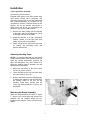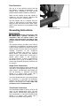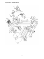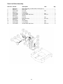
1
Operating Instructions and Parts Manual
20-inch Disc Sander
Model DS20
Three Phase model shown
WALTER MEIER (Manufacturing) Inc.
427 New Sanford Road
LaVergne, TN 37086
Ph.: 800-274-6848
www.powermatic.com
Part No. M-0460226
Revision G 01/2010
Copyright © 2010 Walter Meier (Manufacturing) Inc.
Warranty and Service
Walter Meier (Manufacturing) Inc., warrants every product it sells. If one of our tools needs service or repair, one of our
Authorized Service Centers located throughout the United States can give you quick service. In most cases, any of these Walter
Meier Authorized Service Centers can authorize warranty repair, assist you in obtaining parts, or perform routine maintenance
and major repair on your POWERMATIC® tools. For the name of an Authorized Service Center in your area call 1-800-274-6848.
MORE INFORMATION
Walter Meier is consistently adding new products to the line. For complete, up-to-date product information, check with your local
Walter Meier distributor, or visit powermatic.com.
WARRANTY
POWERMATIC products carry a limited warranty which varies in duration based upon the product.
WHAT IS COVERED?
This warranty covers any defects in workmanship or materials subject to the exceptions stated below. Cutting tools, abrasives
and other consumables are excluded from warranty coverage.
WHO IS COVERED?
This warranty covers only the initial purchaser of the product.
WHAT IS THE PERIOD OF COVERAGE?
The general POWERMATIC warranty lasts for the tim e period specified in the product literature of each product.
WHAT IS NOT COVERED?
The Five Year Warranty does not cover products used for commercial, industrial or educational purposes. Products with a Five
Year Warranty that are used for commercial, industrial or education purposes revert to a One Year Warranty. This warranty does
not cover defects due directly or indirectly to misuse, abuse, negligence or accidents, normal wear-and-tear, improper repair or
alterations, or lack of maintenance.
HOW TO GET SERVICE
The product or part must be returned for examination, postage prepaid, to a location designated by us. For the name of the
location nearest you, please call 1-800-274-6848.
You must provide proof of initial purchase date and an explanation of the complaint must accompany the merchandise. If our
inspection discloses a defect, we will repair or replace the product, or refund the purchase price, at our option.
We will return the repaired product or replacement at our expense unless it is determined by us that there is no defect, or that the
defect resulted from causes not within the scope of our warranty in which case we will, at your direction, dispose of or return the
product. In the event you choose to have the product returned, you will be responsible for the handling and shipping costs of the
return.
HOW STATE LAW APPLIES
This warranty gives you specific legal rights; you may also have other rights which vary from state to state.
LIMITATIONS ON THIS WARRANTY
WALTER MEIER (MANUFACTURING) INC., LIMITS ALL IMPLIED WARRANTIES TO THE PERIOD OF THE LIMITED
WARRANTY FOR EACH PRODUCT. EXCEPT AS STATED HEREIN, ANY IMPLIED WARRANTIES OR MERCHANTABILITY
AND FITNESS ARE EXCLUDED. SOME STATES DO NOT ALLOW LIMITATIONS ON HOW LONG THE IMPLIED WARRANTY
LASTS, SO THE ABOVE LIMITATION MAY NOT APPLY TO YOU.
WALTER MEIER (MANUFACTURING) INC., SHALL IN NO EVENT BE LIABLE FOR DEATH, INJURIES TO PERSONS OR
PROPERTY, OR FOR INCIDENTAL, CONTINGENT, SPECIAL, OR CONSEQUENTIAL DAMAGES ARISING FROM THE USE
OF OUR PRODUCTS. SOME STATES DO NOT ALLOW THE EXCLUSION OR LIMITATION OF INCIDENTAL OR
CONSEQUENTIAL DAMAGES, SO THE ABOVE LIMITATION OR EXCLUSION MAY NOT APPLY TO YOU.
Walter Meier sells through distributors only. The specifications in Walter Meier catalogs are given as general information and are
not binding. Members of Walter Meier reserve the right to effect at any time, without prior notice, those alterations to parts,
fittings, and accessory equipment which they may deem necessary for any reason whatsoever.
2
Table of Contents
Warranty and Service..........................................................................................................................2
Table of Contents ...............................................................................................................................3
Warning .............................................................................................................................................4
Introduction ........................................................................................................................................6
Specifications .....................................................................................................................................6
Unpacking ..........................................................................................................................................6
Installation..........................................................................................................................................7
Attaching Sanding Paper .................................................................................................................7
Mounting the Brake Assembly ..........................................................................................................7
Dust Collection ................................................................................................................................8
Grounding Instructions ........................................................................................................................8
Extension Cords ..............................................................................................................................9
On-Off Switch Padlock .....................................................................................................................9
Adjustments ..................................................................................................................................... 10
Table Movement ........................................................................................................................... 10
Squaring the Table ........................................................................................................................ 10
Replacing Abrasive Disc ................................................................................................................ 10
Miter Gauge .................................................................................................................................. 11
Operation ......................................................................................................................................... 11
Forward-Reverse........................................................................................................................... 12
Brake............................................................................................................................................ 12
Replacement Parts ........................................................................................................................... 14
Parts List: DS20 Disc Sander ......................................................................................................... 15
Exploded View: DS20 Disc Sander ................................................................................................. 17
Parts List: Brake Assembly ............................................................................................................ 18
Electrical Connections....................................................................................................................... 19
3
Warning
1. Read and understand the entire owner’s manual before attempting assembly or operation.
2. Read and understand the warnings posted on the machine and in this manual. Failure to comply with
all of these warnings may cause serious injury.
3. Replace the warning labels if they become obscured or removed.
4. This disc sander is designed and intended for use by properly trained and experienced personnel
only. If you are not familiar with the proper and safe operation of a disc sander, do not use until
proper training and knowledge have been obtained.
5. Do not use this disc sander for other than its intended use. If used for other purposes, Walter Meier
(Manufacturing) Inc., disclaims any real or implied warranty and holds itself harmless from any injury
that may result from that use.
6. Always wear approved safety glasses/face shields while using this disc sander. Everyday eyeglasses
only have impact resistant lenses; they are not safety glasses.
7. Before operating this disc sander, remove tie, rings, watches and other jewelry, and roll sleeves up
past the elbows. Remove all loose clothing and confine long hair. Non-slip footwear or anti-skid floor
strips are recommended. Do not wear gloves.
8. Wear ear protectors (plugs or muffs) during extended periods of operation.
9. Do not operate this machine while tired or under the influence of drugs, alcohol or any medication.
10. Make certain the switch is in the OFF position before connecting the machine to the power supply.
11. Make certain the machine is properly grounded.
12. Make all machine adjustments or maintenance with the machine unplugged from the power source.
13. Some dust created by power sanding, sawing, grinding, drilling and other construction activities
contain chemicals known to cause cancer, birth defects or other reproductive harm. Some examples
of these chemicals are:
•
•
Lead from lead based paint.
Crystalline silica from bricks, cement and other masonry products.
•
Arsenic and chromium from chemically treated lumber.
Your risk of exposure varies, depending on how often you do this type of work. To reduce your
exposure to these chemicals, work in a well-ventilated area and work with approved safety
equipment, such as face or dust masks that are specifically designed to filter out microscopic
particles.
14. Remove adjusting keys and wrenches. Form a habit of checking to see that keys and adjusting
wrenches are removed from the machine before turning it on.
15. Keep safety guards in place at all times when the machine is in use. If removed for maintenance
purposes, use extreme caution and replace the guards immediately.
16. Check damaged parts. Before further use of the machine, a guard or other part that is damaged
should be carefully checked to determine that it will operate properly and perform its intended
function. Check for alignment of moving parts, binding of moving parts, breakage of parts, mounting
and any other conditions that may affect its operation. A guard or other part that is damaged should
be properly repaired or replaced.
17. Provide for adequate space surrounding work area and non-glare, overhead lighting.
18. Keep the floor around the machine clean and free of scrap material, oil and grease.
19. Keep visitors a safe distance from the work area. Keep children away.
20. Make your workshop child proof with padlocks, master switches or by removing starter keys.
4
21. Give your work undivided attention. Looking around, carrying on a conversation and “horse-play” are
careless acts that can result in serious injury.
22. Maintain a balanced stance at all times so that you do not fall or lean against the disc or other moving
parts. Do not overreach or use excessive force to perform any machine operation.
23. Support the workpiece with the miter gauge; maintain control of the workpiece at all times.
24. Use the right tool at the correct speed and feed rate. Do not force a tool or attachment to do a job for
which it was not designed. The right tool will do the job better and safer.
25. Use recommended accessories; improper accessories may be hazardous.
26. Maintain tools with care. Follow instructions for lubricating and changing accessories.
27. Turn off the machine before cleaning. Use a brush or compressed air to remove chips or debris — do
not use your hands.
28. Do not stand on the machine. Serious injury could occur if the machine tips over.
29. Never leave the machine running unattended. Turn the power off and do not leave the machine until it
comes to a complete stop.
30. Remove loose items and unnecessary work pieces from the area before starting the machine.
31. After turning switch to “ON,” always allow the disc to come up to full speed before sanding or
grinding. Keep hands clear of the disc.
32. Do not wet grind or polish. Never use a steady stream of water on the workpiece. Only quench the
workpiece in water to cool it.
33. Do not grind or polish magnesium as it may catch on fire.
34. Replace sanding discs when they become loaded and glazed or frayed.
Familiarize yourself with the following safety notices used in this manual:
This means that if precautions are not heeded, it may result in minor injury and/or
possible machine damage.
even death.
This means that if precautions are not heeded, it may result in serious injury or possibly
5
Introduction
This manual is provided by Walter Meier (Manufacturing) Inc., covering the safe operation and
maintenance procedures for a Powermatic Model DS20 Disc Sander. This manual contains instructions
on installation, safety precautions, general operating procedures, maintenance instructions and parts
breakdown. This machine has been designed and constructed to provide years of trouble free operation if
used in accordance with instructions set forth in this manual. If there are any questions or comments,
please contact either your local supplier or Walter Meier. Walter Meier can also be reached at our web
site: www.waltermeier.com.
Specifications
Model Number ............................................................................................................................. DS20
Stock Number (3HP, 3Ph, 230/460V – prewired 230V)...............................................................1791264
Stock Number (2HP, 1Ph, 230V) ..............................................................................................1791276
Disc Diameter (in.) ............................................................................................................................ 20
Table Tilt (deg.) ............................................................................................................. 30 up, 45 down
Table Size (in.) .............................................................................................................. 27-1/2 x 10-1/2
Table Surface from Floor, minimum height (in.) ........................................................................... 28-3/16
Table Surface from Floor, maximum height (in.) ............................................................................ 35-7/8
Distance Between Disc and Table (in.) ............................................................................................ 0.20
Distance Between Mounted Abrasive and Table (in.)........................................................................ 0.17
Dust Port Diameter (in.)....................................................................................................................... 4
Dust Collection Minimum CFM Required .......................................................................................... 600
Disc Speed (RPM) ....................................................................................................................... 1,720
Overall Size (LxWxH)(in.) .............................................................................................. 31 x 28 x 48-1/2
Footprint (LxW)(in.) ........................................................................................................ 22-1/2 x 22-1/2
Net Weight, approximate (lbs.)......................................................................................................... 426
Shipping Weight, approximate (lbs.) ................................................................................................. 529
The above specifications were current at the time this manual was published, but because of our policy of
continuous improvement, Walter Meier reserves the right to change specifications at any time and without
prior notice, without incurring obligations.
Unpacking
Open shipping container and check for shipping
damage. Report any damage immediately to
your distributor and shipping agent. Do not
discard any shipping material until the Disc
Sander is installed and running properly. Read
the instruction manual thoroughly for assembly,
maintenance and safety instructions.
Contents of shipping container:
1
1
1
1
1
DS20 Disc Sander
20” Abrasive Paper
Brake Assembly
Instruction and Parts Manual
Warranty Card
6
Installation
Tools required for assembly:
6mm hex key (“Allen wrench”)
Exposed metal areas of the Disc Sander have
been factory coated with a protectant. This
should be removed with a soft cloth dampened
with a cleaner/degreaser, or kerosene. Do not
use gasoline, acetone or lacquer thinner for this
purpose. Do not get solvents near plastic or
rubber parts, and do not use an abrasive pad
because it may scratch metal surfaces.
1. Remove the bolts holding the Disc Sander
to the pallet, and use an assistant or a hoist
to slide the machine off the pallet.
2. Install the machine in a level, well-lighted
location. Secure it to the floor with good
quality anchor bolts (not provided).
3. Leave enough space around the work area
for loading and off-loading stock and
general maintenance.
Attaching Sanding Paper
NOTE: It is recommended that you first inspect
certain measurements at the disc/table area and
make any needed adjustments (squaring the
table, disc adjustment, etc.); this is easier to do
before the sanding paper is attached. See the
appropriate sections below.
1. Make sure the surface of the disc is clean
and free of grease or debris.
2. Lower the table all the way and push back
the guard (refer to Figure 5).
3. Remove the backing from the sanding paper
to expose the adhesive, and carefully apply
the sanding paper to the disc on the
machine. Press firmly, starting from the
center and working outward, to remove any
air bubbles.
Mounting the Brake Assembly
Attach the brake assembly as shown in Figure
1, using the two socket head cap screws, lock
washers, and flat washers which are preinstalled on the machine. Use a 6mm hex key to
tighten.
Figure 1
7
Dust Collection
The use of a dust collection system with the
Disc Sander is strongly recommended. It will
maintain shop cleanliness, and help prevent
possible health hazards caused by wood dust.
Make sure the capacity of the dust collector is
suitable for this size machine. Minimum 600
cubic feet per minute is recommended.
The Disc Sander has a 4” diameter dust port
(Figure 2). Slide the hose of your dust collector
over the outlet, and secure with a hose clamp.
NOTE: Dryer vent hose is not acceptable for this
purpose.
Figure 2
hose not included
Grounding Instructions
Electrical connections must
be made by a qualified electrician in
compliance with all relevant codes. This
machine must be properly grounded to help
prevent electrical shock and possible fatal
injury.
This machine must be grounded. In the event of
a malfunction or breakdown, grounding provides
a path of least resistance for electric current, to
reduce the risk of electric shock to the operator.
Improper connection of the equipmentgrounding conductor can result in a risk of
electric shock. The conductor, with insulation
having an outer surface that is green with or
without yellow stripes, is the equipmentgrounding conductor. If repair or replacement of
the electric cord or plug is necessary, do not
connect the equipment-grounding conductor to a
live terminal.
Single Phase Connections
The single phase Sander is factory wired for 230
volts only. It is not supplied with a plug. You may
either install a UL/CSA-listed plug suitable for
230 volt operation, or “hard-wire” the Sander
directly to a service panel (make sure a
disconnect is available for the operator).
It is recommended that the single phase Sander
be connected to a grounded and dedicated,
minimum 30 amp circuit with a 30 amp circuit
breaker or time delay fuse. Local codes take
precedence over recommendations.
Three Phase Connections
The three phase Sander is factory wired for 230
volts. It is not supplied with a plug. You may
either install a UL/CSA-listed plug suitable for
230 volt operation, or “hard-wire” the Band Saw
directly to a service panel (make sure a
disconnect is available to the operator).
8
The three phase Band Saw may be converted to
460 volt operation. Re-connect the motor leads
according to the diagram inside the motor
junction box. (Similar diagrams may be found at
the back of this manual; however, diagrams on
the machine itself should take precedence.)
Recommended Gauges (AWG) of Extension Cords
Extension Cord Length *
It is recommended that the three phase 230V
Sander be connected to a grounded and
dedicated, minimum 20 amp circuit with a 20
amp circuit breaker or time delay fuse. It is
recommended that the three phase 460V sander
be connected to a grounded and dedicated,
minimum 15 amp circuit with a 15 amp circuit
breaker or time delay fuse. Local codes take
precedence over recommendations.
If the Sander is to be hard-wired, make sure the
fuses have been removed or the breakers have
been tripped in the circuit to which the Sander
will be connected. Place a warning placard on
the fuse holder or circuit breaker to prevent it
being turned on while the machine is being
wired.
Amps
25
feet
50
feet
75
feet
100
feet
150
feet
200
feet
<5
16
16
16
14
12
12
5 to 8
16
16
14
12
10
NR
8 to 12
14
14
12
10
NR
NR
12 to 15
12
12
10
10
NR
NR
15 to 20
10
10
10
NR
NR
NR
21 to 30
10
NR
NR
NR
NR
NR
*based on limiting the line voltage drop to 5V at 150% of the
rated amperes.
NR: Not Recommended.
Figure 3
Make sure the voltage of your power supply
matches the specifications on the motor plate of
the Disc Sander.
Extension Cords
If an extension cord is necessary make sure the
cord rating is suitable for the amperage listed on
the machine's motor plate. An undersize cord
will cause a drop in line voltage resulting in loss
of power and overheating.
The chart in Figure 3 shows the correct size
cord to use based on cord length and motor
plate amp rating. If in doubt, use the next
heavier gauge. The smaller the gauge number
the heavier the cord.
On-Off Switch Padlock
The sander is equipped with a push-button
switch that will accept a safety padlock (not
included). See Figure 4. To safeguard your
machine from unauthorized operation and
accidental starting by young children, the use of
a padlock is highly recommended. A padlock
(Stock No. 709012-A) is available from your
local authorized JET distributor or by calling
Walter Meier (Manufacturing) Inc., at the phone
number on the cover of this manual.
Figure 4
9
Adjustments
Table Movement
The work table (A, Figure 5) can be tilted 30
degrees forward and 45 degrees backward.
1. Loosen the handle (B, Figure 5) and rotate
the handwheel (C, Figure 5) clockwise to tilt
table backward, and counterclockwise to tilt
table forward. The pointer on the trunnion
scale (D, Figure 5) indicates the angle.
2. When table is positioned, re-tighten handle
(B, Figure 5).
The table can also be raised or lowered on the
column:
1. Loosen the lock handle (E, Figure 6) and
adjust the table height by rotating the
handwheel (F, Figure 6); clockwise to lower
the table, counterclockwise to raise it.
2. When finished, re-tighten lock handle (E,
Figure 6).
Squaring the Table
Figure 5
1. Verify the accuracy of the scale pointer by
positioning the table in horizontal position,
and placing a square on the table and flus h
against the disc. (It is easier to do this
without an abrasive disc attached.) See
Figure 7.
2. Adjust the table until the square is flus h
against both surfaces.
3. If required, adjust the pointer to the zero
mark, and retighten the screw.
Replacing Abrasive Disc
The DS20 takes standard 20” diameter cloth or
paper-back sanding discs. We recommend 60
grit for coarse or rough sanding, 80 grit for
general purpose medium duty sanding, and 100
grit for fine sanding.
Figure 6
1. Lower the table as far as possible, and pus h
back the guard. See Figure 5.
2. Use a putty knife to remove the old abrasive
from the disc. Clean the disc with solvent
and allow to dry.
3. Mount the new sanding paper. Sanding
paper is available in various forms, such as
adhesive backed discs and pressuresensitive discs.
4. Raise the table, and pull the guard back
over the disc before operating the sander.
Figure 7
10
Miter Gauge
The miter gauge is equipped with individually
adjustable index stops at 90 degrees and 45
degrees right and left. The index stops can be
adjusted by loosening the hex nut (G, Figure 8)
and turning the screw (H, Figure 8).
Check the accuracy of the 90-degree stop by
placing a square against the miter gauge and
the disc, as shown in Figure 9.
To operate the miter gauge, loosen knob (J,
Figure 8) and move the body of the miter gauge
(K, Figure 8) to the desired angle. Re-tighten
knob before sanding operation.
Figure 8
The miter gauge body is set to stop at 0 degrees
and 45 degrees left or right. To move the gauge
body beyond these points, the stop (L, Figure 8)
must be flipped out of the way.
Operation
Raise the table into position, as shown in Figure
10. After turning on the sander, allow the disc to
come up to full speed before beginning to sand.
Slide the miter gauge into the table slot. The
miter gauge can be used from either direction to
facilitate the position of the workpiece.
Figure 9
Use both hands to hold the workpiece against
the miter gauge and sanding disc.
Keep the workpiece on the side of the disc that
is rotating downward (see Figure 10). This will
prevent the workpiece from being thrown
upward by the rotational force of the disc.
When sanding long workpieces, use supports
which are the same height as the sander table.
Figure 10
11
Forward-Reverse
The three phase model of the DS20 has a
Forward-Reverse switch (Figure 11). When
changing direction with the Forward-Reverse
switch, turn the lever to the OFF position and
allow the disc to come to a complete stop. (Use
the brake for immediate stop). Then turn the
lever to the opposite direction, and allow the
disc to come up to speed.
Brake
Pull the brake handle until the pad contacts the
rotating disc.
Figure 11
(3 Phase model only)
Apply the brake only when
the switch is OFF (On the three-phase model,
only when the main switch is OFF, or the
Forward/Reverse switch is OFF). Damage to
the machine can occur if the brake is applied
while the switch is ON.
Maintenance
Before
doing
any
maintenance on the machine, disconnect it
from the electrical supply by pulling out the
plug or switching off the main switch!
Failure to comply may cause serious injury.
The
DS20
Sander
requires
minimal
maintenance. Periodically, make sure the rack
and the trunnions on both sides of the table
(Figure 12) are lubricated with a good grade,
non-hardening grease.
The table surface must be kept clean and free of
rust for best results. If rust appears, use a
mixture of household ammonia, a good
commercial detergent and #000 steel wool.
Alternatively, commercial rust removers can be
found at many hardware stores.
Figure 12
Apply a light, protective coating over the table,
such as paste wax. Products in aerosol form are
also available in hardware stores and supply
catalogs. Whatever method is chosen, the
coating should protect the metal and provide a
smooth surface, without staining the wood.
If the power cord is worn, cut or damaged in any
way, have it replaced immediately.
12
Troubleshooting
Trouble
Probable Cause
Remedy
Machine will not
start/restart or
repeatedly trips
circuit breakers or
blows fuses.
Machine not connected to
power source.
Verify machine is connected to power.
Fuse blown, or circuit
breaker tripped.
Replace fuse, or reset circuit breaker.
Cord damaged.
Replace cord.
Extension cord too light or
too long.
Use adequate size extension cord.
Building circuit breaker trips
or fuse blows.
Verify that sander is on a circuit of correct size. If
circuit size is correct, there is probably a loose
electrical lead.
Loose electrical
connections.
Go through all the electrical connections on the
edge sander including motor connections, verifying
the tightness of each. Look for any signs of
electrical arcing which is a sure indicator of loose
connection or circuit overload.
Switch or motor failure (how
to distinguish).
If you have access to a voltmeter, you can
separate a switch failure from a motor failure by
first, verifying incoming voltage at 220+/-20 and
second, checking the voltage between switch and
motor at 220+/-20. If incoming voltage is incorrect,
you have a power supply problem. If voltage
between switch and motor is incorrect, you have a
switch problem. If voltage between switch and
motor is correct, you have a motor problem.
Motor failure.
If electric motor is suspect, you have two options:
Have a qualified electrician test the motor for
function or remove the motor and take it to a
qualified electric motor repair shop and have it
tested.
On/Off switch failure.
(or Forward/Reverse switch
on 3 phase model).
Disc won’t come
up to speed.
Excessive
replacement of
sanding paper.
If the switch is suspect, you have two options:
Have a qualified electrician test the switch for
function, or purchase a new switch and establish if
that was the problem on changeout.
Extension cord too light or
too long.
Use adequate size extension cord.
Low (incoming) voltage.
Contact qualified electrician.
Excessive bite, or feed
pressure too great.
Allow sanding disc to cut freely, do not force.
Too much pressure being
used during cuts.
Reduce pressure.
Not using full width of belt.
Stroke across the belt using full width.
13
Trouble
Probable Cause
Remedy
Machine vibrates
excessively.
Sander base not level with
floor.
Shim if necessary.
Not secured to the floor.
Use lag screws through holes in base to secure
machine to the floor.
Improper motor mounting.
Check and adjust mounting.
Sanding paper too coarse
for required finish.
Use proper grit. Coarser grits for stock removal,
and finer grits for finish work.
Workpiece sanded across
grain.
When surface sanding, use fine sanding disc
paper then finish by hand, working in direction of
grain.
Sanding grains
quickly rub off
paper.
Sanding paper has lost its
original properties.
Do not store sanding paper in extremely dry or
high-temperature areas. Do not fold sanding disc
papers, store them flat.
Sanding paper
becomes glazed.
Sanding painted surface.
Use open-end grain/flint sanding paper.
Wood is wet or gummy.
No cure. Use different stock.
Wrong sanding paper
surface.
Use coarser grit for stock removal.
Feed pressure too great.
Do not force workpiece into disc. Use just enough
pressure, and let the sanding disc do the work.
Sanding paper
burns, or clogs
quickly.
Too much pressure,
sanding disc biting too
deeply into workpiece.
Adjust for slight sanding action and make several
passes.
Workpiece pulled
from hand.
No support for workpiece.
Use miter gauge. Keep workpiece firmly down
against table.
Sanded edge is
not square.
Result of freehand sanding.
Keep workpiece flat on table at all times when a
square edge is desired. Use miter gauge to ensure
workpiece is square with sanding disc.
Table scale inaccurate.
Check table alignment to disc with a machinist’s
square. It should be 90 degrees. Adjust pointer
and table angle if necessary.
Sanding marks on
workpiece.
Burn marks on
workpiece.
Replacement Parts
Replacement parts are listed on the following pages. To order parts or reach our service department, call
1-800-274-6848, Monday through Friday (see our website for business hours, www.powermatic.com).
Having the Model Number and Serial Number of your machine available when you call will allow us to
serve you quickly and accurately.
14
Parts List: DS20 Disc Sander
Index No. Part No.
Description
Size
Qty
1 .............. 6295560 ..................Base .................................................................................................. 1
2 .............. 6295561 ..................Column .............................................................................................. 1
3 .............. 6295562 ..................Rack .................................................................................................. 1
4 .............. 6295563 ..................Socket Head Cap Screw .............................5/16”-18 x 1/2" .................. 2
5 .............. 6295564 ..................Column Support ................................................................................. 1
6 .............. 6295565 ..................Motor Base......................................................................................... 1
7 .............. 6295566 ..................Stud ................................................................................................... 1
8 .............. 6295567 ..................Flat Washer................................................1/2" .................................. 1
9 .............. 6295568 ..................Spring Washer............................................1/2" .................................. 1
10 ............ 6295569 ..................Hex Nut......................................................1/2" .................................. 1
11 ............ 6295570 ..................Worm Gear ........................................................................................ 1
12 ............ 6295571 ..................Bushing.............................................................................................. 1
13 ............ 6295572 ..................Flat Washer........................................................................................ 1
14 ............ 6295573 ..................Lock Handle Assembly ........................................................................ 1
15 ............ 6295574 ..................Bushing.............................................................................................. 1
16 ............ 6295575 ..................Table Lifting Worm.............................................................................. 1
17 ............ 6295576 ..................Roll Pin ......................................................3 x 20mm ......................... 2
18 ............ 6295577 ..................Shaft .................................................................................................. 1
19 ............ 6295578 ..................Shaft Support Bracket ......................................................................... 1
20 ............ 6295579 ..................Spring Washer............................................1/4” ................................ 10
21 ............ 6295580 ..................Hex Head Screw.........................................1/4"-20 x 1" .................... 10
22 ............ 6295581 ..................Handwheel ......................................................................................... 1
23 ............ 6295582 ..................Handle ............................................................................................... 2
24 ............ 6295583 ..................Set Screw ..................................................5/16"-18 x 3/8" .................. 4
25 ............ 6295584 ..................Hex Head Screw.........................................5/16"-18 x 1-3/4" ............... 2
26 ............ 6295585 ..................Hydraulic Cylinder............................................................................... 1
27 ............ 6295586 ..................Cylinder Head .................................................................................... 2
28 ............ 6295587 ..................Cylinder Fitting ................................................................................... 2
29 ............ 6295588 ..................E-Ring ............................................................................................... 2
30 ............ 6295589 ..................Wire Protector .................................................................................... 1
31 ............ 6295590 ..................Motor .........................................................2HP, 1Ph, 230V ................ 1
................ 6295591 ..................Motor .........................................................3HP, 3Ph, 230/460V ......... 1
................ DS20-SC .................Start Capacitor (not shown) .........................500MFD, 250VAC............. 1
................ DS20-RC ................Run Capacitor (not shown) ..........................40uf, 250VAC ................... 1
32 ............ 6295592 ..................Hex Head Screw.........................................3/8"-16 x 1-1/2"................. 3
33 ............ 6295593 ..................Flat Washer................................................3/8" ................................ 16
34 ............ 6295594 ..................Spring Washer............................................3/8" ................................ 15
35 ............ 6295595 ..................Hex Nut......................................................3/8" .................................. 4
36 ............ 6295596 ..................Key ............................................................5 x 5 x20mm..................... 1
37 ............ 6295597 ..................Hub ................................................................................................... 1
38 ............ 6295598 ..................Set Screw ..................................................3/8"-16 x 3/8".................... 2
39 ............ 6295602 ..................Disc ................................................................................................... 1
40 ............ 6295600 ..................Disc Insert .......................................................................................... 1
41 ............ 6295601 ..................Cap Screw .................................................5/16"-18 x 1"..................... 1
42 ............ ...............................Abrasive Disc (local purchase).....................20”Dia., 100 Grit ............... 1
43 ............ 6295603 ..................Disc Guard Bracket ............................................................................. 2
44 ............ 6295604 ..................Flat Washer................................................1/4" .................................. 2
45 ............ 6295605 ..................Hex Head Screw.........................................1/4"-20 x 1-1/4"................. 2
46 ............ 6295606 ..................Lock Nut ....................................................1/4" .................................. 2
47 ............ 6295607 ..................Hex Head Screw.........................................1/4"-20 x 5/8".................... 2
48 ............ 6295608 ..................Hex Nut......................................................1/4" .................................. 3
49 ............ 6295609 ..................Disc Guard Arm (R) ............................................................................ 1
50 ............ 6295610 ..................Disc Guard Arm (L) ............................................................................. 1
51 ............ 6295611 ..................Disc Guard ......................................................................................... 1
52 ............ 6295612 ..................Solid Segment .................................................................................... 1
53 ............ 6295613 ..................Hex Head Screw.........................................3/8"-16 x 1-3/4"................. 8
54 ............ 6295614 ..................Pilot, Right ......................................................................................... 1
15
Index No. Part No.
Description
Size
Qty
55 ............ 6295615 ..................Phillip Head Screw......................................1/4"-20 x 1/2".................... 4
56 ............ 6295616 ..................Spring Pin ..................................................5 x 20mm ......................... 5
57 ............ 6295617 ..................Pilot, Left............................................................................................ 1
58 ............ 6295618 ..................Gear Segment .................................................................................... 1
59 ............ 6295619 ..................Pointer ............................................................................................... 1
60 ............ 6295620 ..................Round Head Screw ............................................................................. 1
61 ............ 6295621 ..................Trunnion ............................................................................................ 1
62 ............ 6295622 ..................Hex Head Screw.........................................3/8"-16 x 1" ...................... 4
63 ............ 6295623 ..................Table ................................................................................................. 1
64 ............ 6295624 ..................Bolt .................................................................................................... 1
65 ............ 6295625 ..................Roll Pin ......................................................3 x 16mm ......................... 1
66 ............ 6295626 ..................Table Lock Handle .............................................................................. 1
67 ............ 6295627 ..................Table Tilting Worm.............................................................................. 1
68 ............ 6295628 ..................Shaft .................................................................................................. 1
69 ............ 6295629 ..................Handwheel ......................................................................................... 1
70 ............ 6295630 ..................Hex Nut......................................................3/8" .................................. 2
71 ............ 6295631 ..................Gear Housing ..................................................................................... 1
72 ............ 6295632 ..................Scale ................................................................................................. 1
73 ............ 6295633 ..................Hex Head Screw.........................................3/16"-24 x 3/4" .................. 2
74 ............ 6295634 ..................Hex Nut......................................................3/16" ................................ 2
75 ............ 6295635 ..................Switch Plate ....................................................................................... 1
76 ............ 6295636 ..................Switch, Fwd/Rev (3 Phase only) .......................................................... 1
77 ............ 6295637 ..................Round Head Screw .....................................3/16"-24 x 3/4" .................. 9
78 ............ 6295638 ..................Switch Cover ...................................................................................... 1
79 ............ 6295639 ..................Switch, On/Off .................................................................................... 1
80 ............ 6295640 ..................Switch Faceplate ................................................................................ 1
81 ............ 6295641 ..................Tap Screw.......................................................................................... 2
82 ............ 6295642 ..................Set Screw ..................................................1/4"-20 x 1" ...................... 1
83 ............ 6295643 ..................Power Cord ........................................................................................ 1
84 ............ 6295644 ..................Motor Wire ......................................................................................... 1
85 ............ 6295645 ..................Switch Wire (3 Phase only).................................................................. 1
86 ............ 6295646 ..................Dust Chute ......................................................................................... 1
87 ............ 6295647 ..................Cap Screw .................................................1/4"-20 x 1/4".................... 2
................ 6295663 ..................Miter Gauge Assembly (includes index # 88 through 98) ....................... 1
88 ............ 6295648 ..................Guide Bar........................................................................................... 1
89 ............ 6295649 ..................Guide Disc ......................................................................................... 1
90 ............ 6295650 ..................Phillip Head Screw......................................1/4"-20 x 1/4".................... 1
91 ............ 6295651 ..................Pointer ............................................................................................... 1
92 ............ 6295652 ..................Set Screw ..................................................1/4"-20 x 1/4".................... 1
93 ............ 6295653 ..................Stop ................................................................................................... 1
94 ............ 6295654 ..................Roll Pin ......................................................3 x 6mm ........................... 1
95 ............ 6295655 ..................Miter Gauge Body ............................................................................... 1
96 ............ 6295656 ..................Knob .................................................................................................. 1
97 ............ 6295657 ..................Round Head Screw .....................................M4 x 0.7 x 20.................... 3
98 ............ 6295658 ..................Hex Nut......................................................M4 ................................... 3
99 ............ 6295659 ..................Hex Nut......................................................5/16" ................................ 2
100 .......... 6295660 ..................Sponge .............................................................................................. 1
16
Exploded View: DS20 Disc Sander
17
Parts List: Brake Assembly
Index No. Part No.
Description
Size
Qty
................ DS20-200 ................Brake Assembly (includes index #1 through 12) ......................................
1 .............. DS20-201 ................Brake Pad .......................................................................................... 1
2 .............. TS-2311081 ............Hex Nut...........................................................M8 ............................. 1
3 .............. DS20-203 ................Push Body ......................................................................................... 1
4 .............. TS-2361061 ............Lock Washer ....................................................M6 ............................. 4
5 .............. TS-1503041 ............Socket Head Cap Screw ...................................M6 x 16 ...................... 4
6 .............. DS20-206 ................Bracket .............................................................................................. 1
7 .............. TS-1540031 ............Hex Nut............................................................M5 ............................. 1
8 .............. TS-2205301 ............Hex Cap Screw ................................................M5 x 30 ...................... 1
9 .............. DS20-209 ................Spring ................................................................................................ 1
10 ............ TS-1550061 ............Flat Washer......................................................M8 ............................. 2
11 ............ TS-2361081 ............Lock Washer ....................................................M8 ............................. 2
12 ............ TS-1504051 ............Socket Head Cap Screw ...................................M8 x 25 ..................... 2
18
Electrical Connections
19