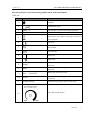
1
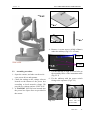
USER MANUAL SLIT LAMP MICROSCOPE Model: GR-7 Version: 1.0 Gilras LLC Version: 1.0 SLIT LAMP MICROSCOPE USER MANUAL Thank you for purchasing our slit lamp microscope. The following is the description and specification of our product. General description This user manual elaborates on the relevant technical specification and operation of the product. The classification of this instrument according to IEC 60601-1-2005 is specified in this manual. Labels and marks required by IEC 60601-1-2005 standard is stuck on the instruments and described in this user manual. Working principle: A beam of light attached to the slit lamp projects to the patients’ eye, which forms an optical section of the living tissue of the eye, in this way the doctor can finish the observation and examination. Slit Lamp Microscopes are used to observe the disease of the anterior structures and tissue damage of eyes. Instruments classification: This instrument is categorized to Class I Type B according to IEC 60601-1-2005 standard, which can not be used under two circumstances: a flammable anesthetic gas and air mixture, oxygen or nitrous oxide gas and air mixture. This instrument can be running continuously. It doesn’t belong to category AP or APG. The specification of this slit lamp microscope. Microscope: Type: Galilean-Type Magnification change: Three steps revolving Drum Eyepieces: 12.5X Angle between eyepieces: 13º Total magnification Ratio: 10X, 16X, 25X Pupilary adjustment: 52mm~78mm Diopter adjustment: 6D Field of view: 25X (8.5mm), 16X (13.5mm), 10X (22mm) Slit Illumination: Slit width: Continuously variable from 0 to 14mm (at 14mm,slit becomes a circle ) Slit length: Continuously variable from 1mm to 14mm Aperture diameters: Slit angle: Filters: Lamp: Luminance: 14mm,8mm,3.5mm,0.5mm 0-180 Heat-absorbing filter, Red-free filter ,Cobalt Blue filter 6V/20W Halogen Lamp 50klx Gilras LLC 2 SLIT LAMP MICROSCOPE USER MANUAL Version: 1.0 Base: Longitudinal movement: Lateral movement: Fine Base movement: Vertical movement: Chin-Rest: Vertical movement: Fixation Target Power: Input voltage: Input frequency: Power Consumption: Output voltage: Light: Fixation: Dimension & Weight: Dimension Gross weight: Net weight: Working environment: Temperature: Relative humidity: Air pressure: Storing environment: Temperature: Relative humidity: Air pressure: Transporting environment: Temperature: Relative humidity: Air pressure: 90mm 100mm 15mm 30mm 80mm LED 220V/110V~10% 50Hz/60Hz 30VA(max) 6V (continuously adjustable) 3V 740mm 450mm x 550mm 22Kg 16Kg +5℃~+40℃ ≤80% 800hpa~1060hpa -40℃~+55℃ ≤93% 700hpa~1060hpa -40℃~+55℃ ≤93% 700hpa~1060hpa Gilras LLC 3 SLIT LAMP MICROSCOPE USER MANUAL Version: 1.0 General Requirements for Safety Please read carefully about following precautions to avoid unexpected personal injury as well as the product being damaged and other possible dangers. Precautions 1. In case there is any trouble, please first refer to the trouble-shooting guide. If it still can’t work, please contact with the authorized distributor or our Repair Department. 2. Do not use this instrument in the environment prone to fire and blast or where there is much dust and with high temperature. Use it in room and simultaneously be careful to keep it clean and dry. 3. Check that all the wires are correctly and firmly connected before using. Ensure that the instrument is well grounded. 4. Please pay attention to all the ratings of the electrical connecting terminal. 5. Turn off the main power first before replacing the main bulb, flash lamp and fuse. 6. When replacing the power cable, please use the power cable in accordance with the notes in the instruction manual. 7. Don’t touch the surface of the lens and prism with hand or hard objects. 8. Please be careful when using the moving parts of the slit lamp, in case that the movement of the base or microscope arm hurts people. 9. To prevent the instrument from falling down to floor, it should be placed on the floor where the inclination angle is less than 10°. 10. Please deal with the waste disposal produced by the machine following relevant laws and regulations. 11. Read carefully the safety and other signals on this machine in order to use the product safely. Gilras LLC 4 SLIT LAMP MICROSCOPE USER MANUAL Version: 1.0 The safety marks, icons and warning symbols stuck on this instrument. Table one: No. mark Description 1 TYPE B 2 Manufacturing date 3 4 Class I Type B The slit lamp is type I medical using equipment English form of B type 5 WEEE mark Please deal with the waste disposal produced by the machine following relevant laws and regulations. 6 CE mark 7 Part Number 8 Serial Number 9 Power ON 10 Power OFF 11 Output At the back of power supply box ,indicate outlet of the power 12 Input At the back of power supply box ,indicate input of the power 13 Fuse 14 Power At the front of power supply box, switch the power on and off 15 Voltage selector Switch the input voltage from 110V to 220V 16 F1AL250V Rated value and current value The mark of light dimmer Gilras LLC 5 SLIT LAMP MICROSCOPE USER MANUAL Version: 1.0 EMC precautions: Other medical instruments and equipment which needs to be installed on the same site using with this instrument shall comply with the same electromagnetic compatibility principle. The equipment which is unable to comply with the electromagnetic compatibility or is known with poor electromagnetic compatibility shall be installed 3 meters at least away from this equipment and powered by different power supply. WEEE precautions: Please dispose the waste electrical and electronic equipment in accordance with relevant regulations and laws. Technical specifications The slit lamp microscope is powered by network power supply. The following marks are required permanently affixed to the instruments according to IEC 60601-1-2005 Standard. The following table lists the tips for your reference. Table two: No. Content Instructions 1 Manufacturer/ supplier Not brand 2 Figure /icon/ mark Detail in table one 3 Connect to main power Detail in power specification 4 Power frequency, Hz 5 Input power frequency 6 Network output power N/A 7 Classification Detail in table one item 3 8 Working time No indication, work continuously 9 Fuse Detail in table one item 11 10 Output Detail in table one item 9 11 Physiological reaction No indication. N/A 12 AP/AGP type device No indication. N/A 13 High pressure terminal device No indication. N/A Detail in power specification Detail in power specification Gilras LLC 6 SLIT LAMP MICROSCOPE USER MANUAL Version: 1.0 14 Cooling condition No indication. N/A 15 Mechanical stability No indication. Detail in Precaution item 8. 16 Protective packing Transportation marks required by <EN ISO 780-1997 packing-handling icon marks> are affixed to the outer packing carton, which includes up, fragile, afraid of the rain, stacking Limit, stacking weight limit and so on. Marks on device The marks on power box of slit lamps. Table 3 No. Content 1 Instructions Protective Earth Terminal Indicator lamp There is indicator lamp on power switch. Green light indicates the power is on, and the instrument is working. 2. Installation of the instrument and working condition Slit lamps are network powered medical instrument. Please check pert the checking list after opening the carton and install the instrument according to this user manual. Test and ensure the instrument operating well before putting to use. 2.1 Replacements of fuse and other consumables 2.1.1 Replacement of fuse The rated value of fuse for this instrument is indicated in table one item 11. And the specification of fuse is also marked on the power box (detail in Chapter 4.6). Spare fuses are provided with this instrument. For more fuses, purchase from your local supplier. 2.1.2 Replacement of other consumables Detail in Chatper 4 of this manual. 3. Electrical circuit drawing and component list 3.1 Electrical circuit drawing Detail in appendix A. 3.2 Component list Gilras LLC 7 SLIT LAMP MICROSCOPE USER MANUAL Version: 1.0 The following electronic components are used in this instrument. Table 4 No. Component name 1 Annulus transformer 2 Light dimmer potentiometer 3 SCR circuit boards 4 Power switch with indicator 5 Metal output socket with four pins 6 220V/110V input voltage selector 7 Network power input socket 8 Light sauce (halogen/ LED lamp) 9 Fixation target 10 fuse 11 Protective earth terminal 3.3 Transport Storage Environmental Limits No special requirements besides the content about transportation and storage of IEC 60601-1-2005 standard. Gilras LLC 8 SLIT LAMP MICROSCOPE USER MANUAL Version: 1.0 Contents EMC PRECAUTIONS: ...........................................................................................................................................6 WEEE PRECAUTIONS: .............................................................................................................................6 1) NOMENCLATURE.......................................................................................................................................10 2) ASSEMBLY....................................................................................................................................................13 3) 4) 2.1 MAIN PARTS CHECK LIST ..........................................................................................................................13 2.2 ASSEMBLY PROCEDURE ............................................................................................................................14 2.3 CHECKING PROCEDURE ............................................................................................................................16 OPERATION PROCEDURES .....................................................................................................................17 3.1 PREPARATION FOR DIOPTER COMPENSATION AND IPD ADJUSTMENT ........................................................17 3.2 PATIENT POSITION AND THE USE OF FIXATION TARGET ..............................................................................18 3.3 BASE OPERATION ......................................................................................................................................18 3.4 OPERATION OF ILLUMINATION SYSTEM.....................................................................................................18 3.5 TIPS OF OPERATION PROCESS ....................................................................................................................19 CLEANING AND DISINFECTION: ...........................................................................................................19 4.1 METHOD OF CLEANING AND DISINFECTION ..............................................................................................19 4.2 CLEANING CIRCLE ....................................................................................................................................20 4.3 MAINTENANCE .........................................................................................................................................20 4.4 PROTECTION.............................................................................................................................................20 4.5 REPLACING THE ILLUMINATION BULB ......................................................................................................20 4.6 REPLACING THE FUSE ...............................................................................................................................21 4.7 REPLACING THE CHIN-REST PAPER ...........................................................................................................22 4.8 CONSUMABLES.........................................................................................................................................22 5. TROUBLE SHOOTING GUIDE......................................................................................................................23 APPENDIX .............................................................................................................................................................24 Gilras LLC 9 SLIT LAMP MICROSCOPE USER MANUAL Version: 1.0 1. Nomenclature 11 12 10 13 14 9 15 16 17 18 19 20 21 22 8 7 6 5 4 3 23 2 1 24 Gilras LLC 10 Version: 1.0 1. 2. 3. 4. 5. 6. 7. 8. 9. 10. 11. 12. 13. 14. 15. 16. 17. 18. SLIT LAMP MICROSCOPE USER MANUAL Work Tabletop Joysticks Incline joystick to move the instrument slightly on the horizontal surface and rotate it to adjust the elevation of the microscope. Brightness Control knob Avoid working continuously at high brightness or the service life of the bulb will be shortened. Base Locking Screw The base will be locked when fastening this screw. Illumination Arm Locking Knob When locking the screw, the illumination system and checking system were connected, when loosing it the illumination system can be used separately. The mark line on the ring of the microscope arm. Together with (6) to indicate the angle between the microscope and illumination unit The indicate of relative angle between the microscope and illumination unit Mark on the angle mark ring of the illumination arm, which relates to the long mark of the microscope arm, represent the two arms’ angle when the”0” on the ring relates to the short mark at one side of the operator the right eyepiece may be blocked, and the side of the patient the left eyepiece. The dial of Aperture Slit Height & the dial of Filter Selection Dial it; there are a few slit heights for selection. Dial it, there are four kinds of filters f or selection. Prism Box Separate the prism box to adjust the interpupillary distance. 12.5X Eyepieces Fixation target Let the patient stare at it and make the patient’s eyes being observed in a stationary state Forehead Belt Make patient’s head in an appropriate position Applanation tonometer adapter Magnification Select Dial Dial it, three different magnification are provided Focusing test rod In order to focus. The Fixation Knob of Chin-rest Paper It is used to fix the chin-rest paper. Chin-rest Supporting the patient’s chin Slit Width Control Knob Gilras LLC 11 Version: 1.0 19. 20. 21. 22. 23. 24. SLIT LAMP MICROSCOPE USER MANUAL The slit width is continuously adjustable within the range from 0 to 14mm.The marks on the left knob stands for the approximant value of the width. Chin-rest Elevation Adjustment Knob Rotate the knob to adjust the elevation of the chin-rest Microscope Arm locking screw Handle (optional accessories) Rail Cover Access line and plug of the brightness control Main Power Switch Turn on the switch, the mark lamp will light Gilras LLC 12 SLIT LAMP MICROSCOPE USER MANUAL Version: 1.0 2. Assembly All parts should be taken out with great care from the packing case before assembling. 2.1 Main parts check List No. Mark Name Quantity Note 1 A Chin-rest part 1 Fig.2.1.1 2 B Microscope part 1 Fig.2.1.2 3 C Illumination part 1 Fig.2.1.3 4 D Tabletop part 1 Fig.2.1.4 5 E Rail cover 1 Fig.2.1.5 6 F Power cable 1 7 G Focusing test rod 1 8 H Dust-proof cover 1 9 I Chin-rest paper 1 10 J Screw driver 1 11 L User manual 1 11 M Packing list 1 Fig.2.1.6 Drawing: Fig.2.1.1 Fig.2.1.2 Gilras LLC 13 SLIT LAMP MICROSCOPE USER MANUAL Version: 1.0 Fig.2.1.3 Fig.2.1.4 Fig.2.1.6 Fig. 2.1.5 4.Remove A team screws (4*M6 x20mm) under the tabletop.(Fig.2.2.1 A Team). B Team A Team Fig2.2.1 2.2 Assembly procedure 1.Open the carton, and take out the tools: cross screw driver and spanner. 2.Check the setting on the voltage selector located on the bottom of the power box according to local network voltage. We provide two voltage options: 220V/110V. 3.A F1AL250V fuse has been inserted into the power box. Spare fuse are provided in the carton. 5.Lift the tabletop to align its screw holes to the assembly holes of the instrument table. (Fig.2.2.2) 6.Fix the tabletop with the power switch facing to the operator. (Fig.2.2.2) The Fig.2.2.2 screws to connect with the electrical table Gilras LLC 14 SLIT LAMP MICROSCOPE USER MANUAL Version: 1.0 7.Connect two white adapters under table board. Turn on and press Up & Down switch to check whether the power table works well. (Fig.2.2.3) Up & Down switch 10. Take out the binocular tubes of microscope part (Fig.2.1.2),match the groove on the binocular tubes with the pin on the microscope body. Fasten the fixing screw on the body to the microscope. Attentions:Don’t touch the objective lens and eyepieces during assembling. White Adapters Fig.2.2.3 The binocular 8.Remove the four screws of B Team with screw drive, and fix the chin-rest part to the tabletop in the way as the following picture shows .(Fig. 2.2.4) tubes Fig.2.1.2 Limit groove Fig.2.2.7 Four screws screw Limit pin Body Fig.2.2.4 Fig 2.2.4 9.Take out the slit lamp part,put it on the rails of the tabletop, and ensure the gears well connected. Move the base to confirm the wheels rolling steadily and then cover the rails with rail covers. (Fig.2.2.5 and 2.2.6). Locking screw on base Insert 11. Make sure the main power plug is not connected (fig.2.2.9). Take out the wire of brightness control knob on the base and connect it to the corresponding socket on the power box. Insert the plug of chin-rest bracket in the correct socket, and fasten it. Rails Fig.2.2.5 Rail Cover Fig.2.2.8 Fig.2.2.6 Gilras LLC 15 SLIT LAMP MICROSCOPE USER MANUAL Version: 1.0 2.3 1. Fuse box 2. Power socket 3. 110V/220V voltage selector 4. Fixation lamp socket 5. Illumination lamp socket 6. Brightness control knob socket Fig 2.2.9 12. Check the voltage selector, this power box support working under the voltage of 110V and 220V. Please select the right voltage according to the voltage in your country. There is a limit groove on the socket. Please Checking procedure 15. A 3 pin cable is supplied with this instrument. Correct plug is supplied as well. Ensure the instrument is grounded. 16. Marks on the power switch: “I” means power on and “O” means power off. The main power switch should be set at the ‘O’ position before connecting the input cable with the power socket. 17. The indicator lamp will be lighted when the instrument is power on (Fig.3.1.3). 18. Insert the focus test rod to right position. A light spot will be projected on the focus test rod. Rotate the slit width knob to adjust the width of the spot and the light dimmer to adjust its brightness. 19. The fixation target is lighted (Fig.3.2.1) 20. Check the following part works flexibly: Aperture changer (Fig.2.3.1) Slit width control knob (Fig.2.3.1) Filter selector (Fig.2.3.1) Joy stick (Fig.2.3.3) Magnification changer lever (Fig.2.3.2) align the plug with the groove. Filter select dial Power box socket Aperture Caution: Wrong power selection may lead to damage of the instruments. 13. Open the fuse box and make sure there is a fuse assembled. Specification of the fuse: F1AL250V 14. Collect tools and spare parts and put them into the drawer under the right side of tabletop. Slit width control knob Fig.2.3.1 Fig.2.3.1 Gilras LLC 16 SLIT LAMP MICROSCOPE USER MANUAL Version: 1.0 Test rod Magnification dial Fig3.1.1 Focal plane Joystick Fig 3.1.2 Fig.2.3.3 ②Brightness adjustment Switch on the main power. Rotate the light dimmer to the central position (Fig.3.1.3). Set the slit width at 2~3mm (Fig.2.3.1). 21. Rotate the light dimmer knob (Fig.3.1.3) and the brightness will go dim. 22. Turn off the main power and cover the instrument with the dust-proof cover after testing. Dark Fig.3.1.3 3. Operation procedures 3.1 Preparation for diopter compensation and IPD adjustment ① Use of the focusing test rod The rod is a standard accessory for accurate adjustment of the microscope. Insert it into the correct poison of slit lamp. With the focal plane facing to the objective lens(Fig.3.1.1 & 3.1.2). Attention : Remove the rod after testing. Bright Light dimmer ③Adjustment of Diopter compensation The focus plane of microscope is calibrated according to the emmetropia. If the operator is ametropia, he should adjust the eyepiece diopter(Fig.3.1.4) according to the following procedures: First, rotate the diopter adjustment ring counter-clockwise to the end. Second, rotate the ring clockwise until the slit image is sharp. Adjust the other eyepiece in the same way. If necessary, record the diopter value on each eyepiece for future reference. Gilras LLC 17 SLIT LAMP MICROSCOPE USER MANUAL Version: 1.0 Diopter 3.3 Base operation adjustment ring 1) Horizontal rough adjustment Move the base back and forth to align microscope with patient’s eye (Fig.3.3.1). Fig.3.1.4 2) Vertical adjustment ④ IPD adjustment Separate the prism box of the microscope to adjust the P.D to get a stereo vision through the microscope (Fig.3.1.5). Rotate the joystick to adjust the microscope’s height until it is perfect to observe the patient’s eye. Rotate the joystick clockwise to raise the microscope and counter-clockwise to lower it (Fig.3.3.1). 3) Horizontal Fine adjustment The prism box Tilt the joystick to move the microscope slightly on the horizontal surface and watch though the eyepieces until a clear and sharp image appear on the field (Fig.3.3.1). Fig.3.1.5 3.2 1) Patient position and the use of fixation target The patient should put chin on the chin-rest and push forehead against the forehead belt. Adjust the elevation of chin-rest until the light of slit lamp projects to the correct position of patient’s eye. (Fig.3.2.1). 2) Joystick Up & Down Fig3.3.1 4) The fixation target is used to attract patient’s attention. Move the tube to put the fixation target at a proper position (Fig.3.2.1). Locking the base When finishing the adjustment, fasten the base locking screw to lock the base and prevent it from sliding. (Fig.3.3.2) Locking screw Fixation Belt Fig.3.3.2 Chin rest 3.4 Handle 1) Fig.3.2.1 Operation of illumination system Changing the aperture and slit height Rotate the aperture and slit height dial to get four round light spots of different diameter sizes: 14mm, Gilras LLC 18 SLIT LAMP MICROSCOPE USER MANUAL Version: 1.0 8mm, 3.5mm, and 0.5mm. Besides the round spot, a wedge-shaped continuous slit spot will be got, whose length is from 1mm to 14mm. The value can be read on the aperture dial (Fig.3.4.1). Aperture Rotate the dial Fig 3.4.1 2) Rotating the slit image Swing the aperture and slit height control knob horizontally to revolve the slit image at any angle from vertical to horizontal direction. The angle of image rotation is indicated by the rotation angle scale with small division for 5° and large division for 10°(Fig.3.4.2). Angle Scale Filter Fig 3.4.2 using the instrument properly. 2) In order to prevent the unnecessary observation misjudgment, read the scales on each knob carefully. 3) Operator should adjust the inter-pupillary distance and diopter correctly in advance in case feeling uncomfortable during observation. 4) Operator may feel dizziness in a long time observation. Take a rest after long time using of the slit lamp. 5) The patients’ eyes will be exposed to the light of slit lamp. The light should be strong enough for observation. Stop observation, if the patient feels uncomfortable. For serious situation please seek for medical treatment. Therefore, avoid prolonged exposure of patients’ eyes in strong light. 4. Cleaning and disinfection: 4.1 Method of cleaning and disinfection 1) Cleaning the lens and reflecting mirror:If there is any dust on the lenses or reflecting mirror, wipe it off with soft cotton dipped in absolute alcohol (Fig.4.1.1). Attention: Do not touch the lens with finger or hard object. Prism 3) Filter selection By rotate the filter dial, three different filters are provided. For general observations, the heat-absorbing filter is placed in position. Set the heat-absorbing filter in position after using the other filters (Fig.3.4.2). 3.5 Tips of operation process Objective Fig.4.1.1 2) Cleaning the sliding pad, rails and shaft:Clean these parts with clean soft cloth regularly to ensure the stable movement of slit lamp. (Fig.4.1.2). 1) Read this user manual carefully to learn the structure and function of slit lamp for Gilras LLC 19 SLIT LAMP MICROSCOPE USER MANUAL Version: 1.0 Rail shaft Slide plate Fig.4.1.2 3) Cleaning and disinfecting the plastic parts: Clean the plastic parts such as chin-rest bracket, forehead-rest belt with soft cloth dipped in soluble detergent or water, and then disinfect these parts with medicinal alcohol. Attention: Don’t wipe these parts with any corrosive detergent in case any surface damage caused. patient. 4) Cleaning the whole machine: Cycle: suggested once per two months. Life cycle of the slit lamp: 4 years. 4.3 Maintenance Correct and periodical protection and maintenance will prolong the service life of the slit lamp. The suggested maintaining cycle is once per two months. 4.4 Protection Cover the main shaft hole with the protection cap to prevent any dust drop in. Remove the cap when the focus test rod needs to be assembled (Fig.4.4.1). 4.2 Cleaning cycle It required that the slit lamp should be stored and used in a clean environment. For prolong the service life of the instrument please clean it regularly per as suggestions below. 1) Clean the eyepieces, objective lens and reflecting mirror: Cycle: suggested once per two months. The lenses and mirror are coated with antireflection coating and the reflective film. Although the coating is strong enough, frequent wipe will lead to damage to the film, and thus affect the observed optical effect. 2) Cleaning the slide pad, rails and shaft: Cycle: suggested once per month Usually, these parts won’t get dirty in normal use. We suggest cleaning these parts once per 6 months for getting smoother movement experience. 3) Cleaning the plastic parts: Cycle: suggested once per day These two parts contact with the patients directly, so please clean and disinfect these two parts timely. Replace a piece of new and clean chin-rest paper for each Protection cap Fig.4.4.1 4.5 Replacing the illumination bulb Caution: the spring blade and the bulb went very hot after a long time of burning. In case any scald injury happens, do not change the bulb until the illumination system is cooling down. 1. Switch off the main power. (Fig.3.1.3); 2. Remove out the fixation knob. Pull up the lamp cap from the illumination unit. Remove the Knob Fig.4.5.1 Gilras LLC 20 SLIT LAMP MICROSCOPE USER MANUAL Version: 1.0 whether the new bulb is illuminating, and if the spot is in good shape without false light. (Fig.3.1.3). Remove the lamp cap 4.6 Replacing the fuse fixing screw Fig.4.5.2 Remove the spring blade Fig.4.5.3 Take bulb holder 1) Switch off the main power and remove the power cable from socket. (Fig.4.6.1). 2) The fuse is inserted in the fuse box which has fuse mark. Please rotate the fuse part out (Fig.4.6.1) by pressing the fuse box with a screw or a coin. One fuse is in use, the other is in spare. Please check them, if the one in use is burnt, please replace it with the spare one and then place both the two fuse parts into original place. Remove the power cable out and Fig.4.5.4 Groove of holder Fig.4.6.3 Replace the fuse Fig.4.6.1 Fig.4.5.5 3. Remove the spring blade(Fig.4.5.2) to take out the original bulb and holder (Fig.4.5.3), and place the new bulb to correct position. Press the spring blade to fix the new bulb. 4. Align the groove on the bulb to the holder; otherwise the illumination may be uneven (Fig.4.5.5). Cover the lamp house with cap and fix the locking screws. 5. Switch on the power and check 3) The fuse specification: F1AL250V Attention: Please select fuse of the same type, specification and rate value. Gilras LLC 21 SLIT LAMP MICROSCOPE USER MANUAL Version: 1.0 4.7 Replacing paper the chin-rest Change the chin-rest paper: remove the two fixation bolts and place the new papers. (Fig.4.7.1) Pull up 4.8 Consumables Fig.4.7.1 1. Fuse: F1AL250 2. Bulb: 6V20W halogen bulb Note: The service life of the halogen bulb is 480 hours. However, it can still work beyond the time limit, while the brightness of the bulb might be lower. Gilras LLC 22 SLIT LAMP MICROSCOPE USER MANUAL Version: 1.0 5. Trouble shooting guide In case there is any trouble, please check according to the following table for reference. If it still cannot work, please contact the Repair Department of an authorized distributor. Trouble Possible cause Remedy The cable isn’t connected correctly with the Connect the power cable power socket correctly No illumination The main power switch is on ‘O’ position Place the switch on ‘I’ position The plug on the power box is loosen Insert the plug firmly The plug on the lamp cap is loosen Insert the plug firmly The bulb has burnt out Change the bulb The fuse has blown Change the fuse The bulb is not assembled properly Assemble properly the bulb The filter lever is in the middle position or in the Set the filter lever to the position of gray filter correct position the brightness adjustment knob is at min. the brightness adjustment knob Voltage selector is wrongly set Set the voltage selector correctly Change the reflecting mirror The coat of the reflecting mirror is oxidized Slit is too dark Too much dust on the reflecting surface Clean the surface with the brush Voltage selector id wrongly set Set the voltage selector properly Replace it with a suitable fuse Fuse has blown The fuse doesn’t comply with the specification Slit width closes automatically Fixation bulb is off The slit width control knob is too loose Adjust the tightness of the control knob The output plug is loose Insert the output plug firmly Gilras LLC 23 SLIT LAMP MICROSCOPE USER MANUAL Version: 1.0 Appendix Electronic Circle Drawing Control plate Halogen bulb Fixation target Transformer Brightness control knob Subject to change in design or specifications without advance notice version: 1.0 20130915 Gilras LLC 24