1
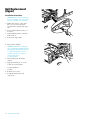
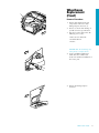
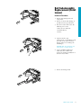
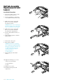
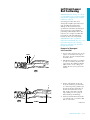
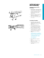
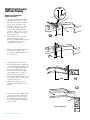
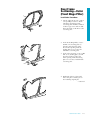
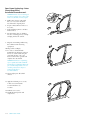
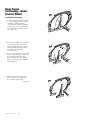
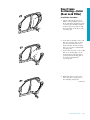
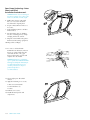
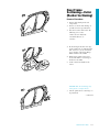
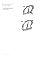
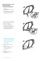
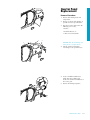
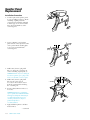
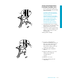
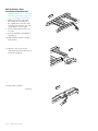
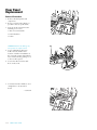
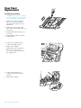
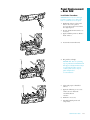
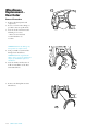
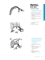
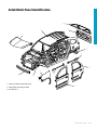
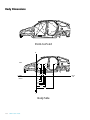
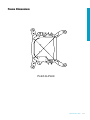
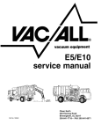
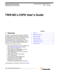
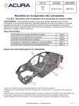
Radiator Support
Replacement
(Upper)
Removal Procedure
1. Remove all related panels and
components including front fascia
supports, right and left (1).
2. Restore as much of the damage as
possible to factory specifications.
3. Note the location and remove the
following as necessary:
1
• Sealers
• Sound deadeners
1
• Anti-corrosion materials
IMPORTANT: Do not damage any
inner panels or reinforcements.
4. Locate and drill out all factory
welds. Note the number and
location of welds for installation of
the Radiator Support Assembly.
5. Remove the damaged Radiator
Support Assembly.
2001 Pontiac Aztek
1-1
2001 Pontiac Aztek
2001 Pontiac Aztek
Radiator Support
Replacement
(Upper)
Installation Procedure
IMPORTANT: In any area damaged
beyond recognition, space plug weld
holes every 40 mm (1-1/2 in) apart.
1. Drill 8 mm (5/16 in) plug weld
holes as necessary in locations
noted from the original panel.
2. Prepare all attachment surfaces as
necessary.
3. Apply weld-thru primer to all baremetal surfaces.
4. Position the Radiator Support
Assembly.
5. Plug weld accordingly.
6. Clean and prepare all welded
surfaces.
IMPORTANT: Prior to refinishing,
refer to publication GM4901M-D-01
GM Approved Refinish Materials for
recommended products. Do not
combine paint systems. Refer to
paint manufacturer’s
recommendations.
7. Apply the following as necessary:
• Anti-corrosion materials
• Sound deadeners
• Sealers
8. Refinish as necessary.
9. Install all related panels and
components.
1-2
2001 Pontiac Aztek
Radiator Support
Replacement
(Lower)
Removal Procedure
1. Remove all related panels and
components.
2. Restore as much of the damage as
possible to factory specifications.
3. Note the location and remove the
following as necessary:
• Sealers
• Sound deadeners
• Anti-corrosion materials
IMPORTANT: Do not damage any
inner panels or reinforcements.
4. Locate and drill out all factory
welds. Note the number and
location of welds for installation of
the Lower Radiator Support.
5. Remove the damaged Lower
Radiator Support.
2001 Pontiac Aztek
1-3
Radiator Support
Replacement
(Lower)
Installation Procedure
IMPORTANT: In any area damaged
beyond recognition, space plug weld
holes every 40 mm (1-1/2 in) apart.
1. Drill 8 mm (5/16 in) plug weld
holes as necessary in locations
noted from the original panel.
2. Prepare all attachment surfaces as
necessary.
3. Apply weld-thru primer to all baremetal surfaces.
4. Position the Lower Radiator
Support.
5. Plug weld accordingly.
6. Clean and prepare all welded
surfaces.
IMPORTANT: Prior to refinishing,
refer to publication GM4901M-D-01
GM Approved Refinish Materials for
recommended products. Do not
combine paint systems. Refer to
paint manufacturer’s
recommendations.
7. Apply the following as necessary:
• Anti-corrosion materials
• Sound deadeners
• Sealers
8. Refinish as necessary.
9. Install all related panels and
components.
1-4
2001 Pontiac Aztek
Rail Replacement
(Upper)
Removal Procedure
1. Remove all related panels and
components.
2. Restore as much of the damage as
possible to factory specifications.
3. Note the location and remove the
following as necessary:
• Anti-corrosion materials
• Sound deadeners
• Sealers
IMPORTANT: Do not damage any
inner panels or reinforcements.
4. Locate and drill out all factory
welds. Note the number and
location of welds for installation of
the Front Upper Rail.
5. Remove the damaged Front Upper
Rail.
2001 Pontiac Aztek
1-5
Rail Replacement
(Upper)
Installation Procedure
IMPORTANT: In any area damaged
beyond recognition, space plug weld
holes every 40 mm (1-1/2 in) apart.
1. Drill 8 mm (5/16 in. ) plug weld
holes as necessary in locations
noted from the original front upper
rail.
2. Prepare all attachment surfaces as
necessary.
3. Apply weld-thru primer to all baremetal surfaces.
4. Position the Upper Rail.
5. Plug weld accordingly.
IMPORTANT: Prior to refinishing,
refer to publication GM4901M-D-01
GM Approved Refinish Materials for
recommended products. Do not
combine paint systems. Refer to
paint manufacturer’s
recommendations.
6. Clean and prepare all welded
surfaces.
7. Apply the following as necessary:
• Anti-corrosion materials
• Sound deadeners
• Sealers
8. Refinish as necessary.
9. Install all related panels and
components.
1-6
2001 Pontiac Aztek
1
Wheelhouse
Replacement
(Front)
Removal Procedure
1. Remove all related panels and
components in the area of the
damaged apron extension (1).
2. Restore as much of the damage as
possible to factory specifications.
3. Note the location and remove the
following as necessary:
• Anti-corrosion materials
• Sound deadeners
• Sealers
IMPORTANT: Do not damage any
inner panels or reinforcements.
4. Locate and drill out all factory
welds. Note the number and
location of welds for installation of
the service part.
5. Remove the damaged apron
extension.
2001 Pontiac Aztek
1-7
Wheelhouse
Replacement
(Front)
Installation Procedure
IMPORTANT: In any area damaged
beyond recognition, space plug weld
holes every 40 mm (1-1/2 in) apart.
1. Drill 8 mm (5/16 in.) plug weld
holes in the service part as
necessary in the locations noted
from the original panel.
2. Prepare all attachment surfaces as
necessary.
IMPORTANT: Prior to refinishing,
refer to the publication GM4901MD-01 GM Approved Refinish
Materials for recommended
products. Do not combine paint
systems. Refer to paint
manufacturer’s recommendations.
3. Apply weld-thru primer to all bare
metal surfaces.
4. Position the apron extension.
5. Plug weld accordingly.
6. Clean and prepare all welded
surfaces.
7. Apply the following as necessary:
• Anti-corrosion materials
• Sound deadening materials
• Sealers
8. Refinish as necessary.
9. Install all related panels and
components.
1-8
2001 Pontiac Aztek
Rail Sub-Assembly
Replacement (Front
Lower)
Removal Procedure
1. Remove all related panels and
components.
2. Restore as much of the damage as
possible to factory specifications.
3. Note the location and remove the
following as necessary:
• Anti-corrosion materials
• Sound deadeners
• Sealers
4. Separate the floor pan
reinforcement (1) weld flanges from
the inside of the lower rail. Care
must be taken not to damage the
weld flanges.
IMPORTANT: Do not damage any
inner panels or reinforcements.
5. Locate and drill out all factory
welds. Note the number and
location of welds for installation of
the Front Lower Rail.
1
6. Remove the damaged rail.
2001 Pontiac Aztek
1-9
Rail Sub-Assembly
Replacement (Front
Lower)
Installation Procedure
1. Prepare the mating surfaces of the
floor pan reinforcement (1).
2. Turn the weld flanges outward (2)
to be welded to the front lower rail.
3. Drill 8 mm (5/16 in.) plug weld
holes as necessary in locations
noted from removal.
IMPORTANT: In any area damaged
beyond recognition, space plug weld
holes every 40 mm (1-1/2 in.) apart.
4. Drill 8 mm (5/16 in.) plug weld
holes as necessary in locations
noted from the original panel.
5. Prepare all attachment surfaces as
necessary.
6. Apply weld-thru primer to all baremetal surfaces.
7. Position the service part
8. Plug weld accordingly.
IMPORTANT: Prior to refinishing,
refer to publication GM4901M-D-01
GM Approved Refinish Materials for
recommended products. Do not
combine paint systems. Refer to
paint manufacturer’s
recommendations.
9. Clean and prepare all welded
surfaces.
10. Apply the following as necessary :
• Anti-corrosion materials
• Sound deadeners
• Sealers
11. Refinish as necessary.
12. Install all related panels and
components.
1-10
2001 Pontiac Aztek
2
1
Left Front Lower
Rail Sectioning
IMPORTANT: If the damage exceeds the
recommended area for sectioning and the
rail cannot be straightened, the complete
rail must be replaced.
Sectioning procedures have been
developed to simplify repair of the lower
rails, providing the majority of the
damage can be returned to factory
specifications. This allows the damaged
front section to be replaced without
performing a full rail replacement. The
rails come as a complete assembly. The
front portion of the rail and bumper
brackets are also serviced separately.
IMPORTANT: Failure to follow the
instructions included with the service rail
may lead to improper rail sectioning,
which may compromise the structural
integrity of the vehicle.
Removal of Damaged
Left Front Rail
1. On top of the rail, locate the cut-out
square (1). From the front edge of
the square, measure forward 25 mm
and scribe a line.
35MM
1
2. Add 10 mm and scribe a second line
(1). The second line (35 mm) is the
cut location. The additional 10 mm
will be used to create a flange for
welding the new service part to the
vehicle.
1
3. On the outboard side of the rail,
locate the brake line pass-thru hole
(1). At the larger hole, pull the tape
measure from the forward edge of
the hole and mark a line at 392
mm. Scribe a line with a straight
edge, making sure it is square to
inboard and top rail markings.
4. Measure forward 10 mm and scribe
a second line. The second line (402
mm) is cut location.
402MM
—continued
2001 Pontiac Aztek
1-11
Removal of Damaged
Left Front Rail con’t
1
5. Locate hole (1), on the inboard side
of the rail. Measure forward 140
mm (5-1/2 in.) and mark the
location. Scribe a straight line on
the rail.
6. Measure forward 10 mm (13/32 in.)
and scribe a second line. The
second line [150 mm (5-29/32 in.)]
is the cut location (2).
2
150MM
7. Make certain all three sides are
aligned. Cut through three sides of
the rail.
8. On the bottom of the damaged rail,
scribe a line from the outboard to
the inboard cut locations and cut
the remainder of the rail (1) from
the vehicle.
9. Remove the damaged section of rail.
1
(LEFT OUTBOARD)
1-12
2001 Pontiac Aztek
Left Front Lower
Rail Sectioning
Preparing Service Part for
Installation
3
1
1. On original rail, cut and remove 10
mm (13/32 in.) of the outboard (1)
and downward (2) turned flanges of
the rail. Cut 10 mm (13/32 in.)
gaps along the corners of the
original rail (3).
2. Step the top, bottom and side tabs
inward (4) to allow the service part
to fit over the original rail.
3. Clean and prepare mating surfaces
as necessary.
4
2
Installation Procedure
1. Position the service part over the
original rail. Align and check fit
using three-dimensional measuring
equipment.
2. Stitch weld along the entire
sectioning joint. Make 25 mm (1
in.) welds along the seam with 25
mm (1 in.) gaps between them.
3. Go back and complete the stitch
weld. This will create a solid weld
joint with minimal heat distortion.
4. Clean and prepare all welded
surfaces.
IMPORTANT: Prior to refinishing,
refer to publication GM4901M-D-01
GM Approved Refinish Materials for
recommended products. Do not
combine paint systems. Refer to
paint manufacturer’s
recommendations.
5. Prime with two-part catalyzed
primer.
6. Apply sealers and anti-corrosion
materials as necessary.
7. Install all related panels and
components.
2001 Pontiac Aztek
1-13
Right Front Lower
Rail Sectioning
18MM
Removal of Damaged
Right Front Rail
1
1. On top of rail, locate the last cutout square. From the rear edge of
the square (1), measure forward 8
mm (5/16 in.) and scribe a line.
2. Add 10 mm and scribe a second
line. The second line is the cut
location. The additional 10 mm
(13/32 in.) will be used to create a
flange for welding the new service
part to the vehicle.
2
160MM
3. On the outboard side of the rail,
locate the fixturing hole (2).
Measure forward 150 mm (5-29/32
in.) and mark location. Scribe a
straight line on the rail.
4. Measure forward 10 mm (13/32 in.)
and scribe a second line. The
second line [160 mm (6-5/16 in.)] is
the cut location.
160MM
5. On the inboard side of the rail,
locate the brake line pass-thru hole
(1). At the larger hole, pull the tape
measure from the forward edge of
the hole and mark a line at 376
mm. Scribe a line with a straight
edge, making sure it is square to
inboard and top rail markings.
6. Measure forward 10 mm and scribe
a second line. The second line (386
mm) is the cut location.
1
386MM
7. Make certain all three sides are
aligned. Cut through three sides of
the rail.
8. On the bottom of the damaged rail,
scribe a line from the outboard to
the inboard cut locations and cut
the remainder of the rail (1) from
the vehicle. Remove the damaged
section of rail.
1
(RIGHT OUTBOARD)
1-14
2001 Pontiac Aztek
Right Front Lower
Rail Sectioning
3
1
Preparing the Undamaged
Portion of the Rail for
Installation
1. On original rail, cut and remove 10
mm of the outboard (1) and
downward (2) turned flanges of the
rail. Cut 10 mm gaps along the
corners of the original rail.
2. Step the top, bottom and side tabs
inward (3) to allow the service part
to fit over the original rail.
4
2
3. Clean and prepare mating surfaces
as necessary.
Installation Procedure
1. Position the service part over the
original rail. Align and check fit
using three-dimensional measuring
equipment.
2. Stitch weld along the entire
sectioning joint. Make 25 mm
(1␣ in.) welds along the seam with 25
mm (1 in.) gaps between them.
3. Go back and complete the stitch
weld. This will create a solid weld
joint with minimal heat distortion.
4. Clean and prepare all welded
surfaces.
IMPORTANT: Prior to refinishing,
refer to publication GM4901M-D-01
GM Approved Refinish Materials for
recommended products. Do not
combine paint systems. Refer to
paint manufacturer’s
recommendations.
5. Prime with two-part catalyzed
primer.
6. Apply sealers and anti-corrosion
materials as necessary.
7. Install all related panels and
components.
2001 Pontiac Aztek
1-15
Door Frame
Sectioning—Outer
(Front Hinge Pillar)
Removal Procedure
1. Remove all related panels and
components.
2. Restore as much of the damage as
possible to factory specifications.
3. Note the location and remove the
following as necessary:
• Anti-corrosion materials
• Sound deadeners (1)
• Sealers
IMPORTANT: Do not damage any
inner panels or reinforcements.
4. Cut the panel where sectioning is to
be performed.
5. Locate and drill out all factory
welds. Note the number and
location of welds for installation of
the service part.
6. Remove the damaged Front Hinge
Pillar.
1-16
2001 Pontiac Aztek
1
1
Door Frame
Sectioning—Outer
(Front Hinge Pillar)
1
Installation Procedure
1. Cut the replacement service part in
corresponding locations to fit the
remaining original panel. The
sectioning joint should be trimmed
to allow a gap of one-and-one-half
times the metal (1) thickness at the
sectioning joint.
1
2. In the Front Hinge Pillar, create a
50 mm (2 in.) backing plate (1)
from the unused portion of the
Door Frame Opening. Trim the
backing plate as necessary to fit
behind the sectioning joint.
3. In the rocker locations, create a 100
mm (4 in.) backing plate (2) from
the unused portion of the door
frame opening. Trim the backing
plate as necessary to fit behind the
sectioning joint.
2
4. Drill 8 mm (5/16 in.) plug weld
holes along the sectioning cut on
the remaining original part
—continued
2001 Pontiac Aztek
1-17
Door Frame Sectioning—Outer
(Front Hinge Pillar)
Installation Procedure con't
IMPORTANT: In any area damaged
beyond recognition, space plug weld
holes every 40 mm (1-1/2 in.) apart.
5. Drill 8 mm (5/16 in.) plug weld
holes as necessary in locations
noted from the original panel.
25MM
(1/2 IN)
2
1
6. Prepare all attachment surfaces as
necessary.
7. Apply weld-thru primer to all baremetal surfaces.
8. Fit the backing plate (1) halfway
into the sectioning joint (2). Clamp
and plug weld to the vehicle.
9. Align the Front Hinge Pillar using
three-dimensional measuring
equipment.
10. Plug weld accordingly.
11. To create a solid weld with
minimum heat distortion, make 25
mm (1 in.) stitch welds along the
seam with 25 mm (1 in.) gaps
between them. Then go back and
complete the stitch weld.
IMPORTANT: Prior to refinishing,
refer to publication GM 4901M-D01 GM Approved Refinish Materials
for recommended products. Do not
combine paint systems. Refer to
paint manufacturer’s
recommendations.
12. Clean and prepare all welded
surfaces.
13. Apply the following as necessary:
• Anti-corrosion materials
• Sound deadeners (1)
• Sealers
14. Refinish as necessary.
15. Install all related panels and
components.
1
1
1-18
2001 Pontiac Aztek
Door Frame
Sectioning—Outer
(Center Pillar)
Removal Procedure
1. Remove all related panels and
components.
2. Restore as much of the damage as
possible to factory specifications.
1
1
3. Note the location and remove the
following as necessary:
• Anti-corrosion materials
• Sound deadeners (1)
• Sealers
IMPORTANT: Do not damage any
inner panels or reinforcements.
4. Cut the panel where sectioning is to
be performed.
5. Locate and drill out all factory
welds. Note the number and
location of welds for installation of
the service part.
6. Remove the damaged Center Pillar.
2001 Pontiac Aztek
1-19
Door Frame
Sectioning—Outer
(Center Pillar)
Installation Procedure
1
1. Cut the replacement Center Pillar
in corresponding locations to fit the
remaining original panel. The
sectioning joint should be trimmed
to allow a gap of one-and-one-half
times the metal (1) thickness at the
sectioning joint.
2. In the Center Pillar, create a 50 mm
(2 in.) backing plate (1) from the
unused portion of the Door Frame
Opening. Trim the backing plate as
necessary to fit behind the
sectioning joint.
3. In the rocker locations, create a 100
mm (4 in.) backing plate (2) from
the unused portion of the door
frame opening. Trim the backing
plate as necessary to fit behind the
sectioning joint.
4. Drill 8 mm (5/16 in.) plug weld
holes along the sectioning cut on
the remaining original part.
—continued
1-20
2001 Pontiac Aztek
1
2
2
Door Frame Sectioning—Outer
(Center Pillar)
Installation Procedure con't
IMPORTANT: In any area damaged
beyond recognition, space plug weld
holes every 40 mm (1-1/2 in.) apart.
25MM
(1 IN)
2
5. Drill 8 mm (5/16 in.) plug weld
holes as necessary in locations
noted from the original panel.
1
6. Prepare all attachment surfaces as
necessary.
7. Apply weld-thru primer to all baremetal surfaces.
8. Fit the backing plate (1) halfway
into the sectioning joint (2) clamp
and plug weld to the vehicle.
9. Align the Center Pillar using threedimensional measuring equipment.
10. Plug weld accordingly.
11. To create a solid weld with
minimum heat distortion, make 25
mm (1 in.) stitch welds along the
seam with 25 mm (1 in.) gaps
between them. Then go back and
complete the stitch weld
100mm
(4 IN)
IMPORTANT: Prior to refinishing,
refer to publication GM 4901M-D01 GM Approved Refinish Materials
for recommended products. Do not
combine paint systems. Refer to
paint manufacturer’s
recommendations.
12. Clean and prepare all welded
surfaces.
13. Apply the following as necessary:
• Anti-corrosion materials
• Sound deadeners (1)
• Sealers
14. Refinish as necessary.
1
15. Install all related panels and
components.
1
2001 Pontiac Aztek
1-21
Door Frame
Sectioning—Outer
(Rear Lock Pillar)
Removal Procedure
1. Remove all related panels and
components.
2. Restore as much of the damage as
possible to factory specifications.
3. Note the location and remove the
following as necessary:
• Anti-corrosion materials
• Sound deadeners (1)
• Sealers
IMPORTANT: Do not damage any
inner panels or reinforcements.
4. Cut the panel where sectioning is to
be performed.
5. Locate and drill out all factory
welds. Note the number and
location of welds for installation of
the service part.
6. Remove the damaged Rear Lock
Pillar.
1-22
2001 Pontiac Aztek
1
1
Door Frame
Sectioning—Outer
(Rear Lock Pillar)
Installation Procedure
1
1. Cut the replacement Rear Lock
Pillar in corresponding locations to
fit the remaining original panel. The
sectioning joint should be trimmed
to allow a gap of one-and-one-half
times the metal (1) thickness at the
sectioning joint.
2. In the Rear Lock Pillar, create a 50
mm (2 in.) backing plate (1) from
the unused portion of the Door
Frame Opening. Trim the backing
plate as necessary to fit behind the
sectioning joint.
1
2
3. In the rocker locations, create a 100
mm (4 in.) backing plate (2) the
unused portion of the door frame
opening. Trim the backing plate as
necessary to fit behind the
sectioning joint.
4. Drill 8 mm (5/16 in.) plug weld
holes along the sectioning cut on
the remaining original part.
—continued
2001 Pontiac Aztek
1-23
Door Frame Sectioning—Outer
(Rear Lock Pillar)
Installation Procedure con't
IMPORTANT: In any area damaged
beyond recognition, space plug weld
holes every 40 mm (1-1/2in.) apart.
25MM
(1 IN)
2
1
5. Drill 8 mm (5/16 in.) plug weld
holes as necessary in locations
noted from the original panel.
6. Prepare all attachment surfaces as
necessary.
7. Apply weld-thru primer to all baremetal surfaces.
8. Fit the backing plate (1) halfway
into the sectioning joint (2) clamp
and plug weld to the vehicle.
9. Align the Center Pillar using threedimensional measuring equipment.
10. Plug weld accordingly.
11. To create a solid weld with
minimum heat distortion, make 25
mm (1 in.) stitch welds along the
seam with 25 mm (1 in.) gaps
between them. Then go back and
complete the stitch weld.
100mm
(4 IN)
IMPORTANT: Prior to refinishing,
refer to publication GM4901M-D-01
GM Approved Refinish Materials for
recommended products. Do not
combine paint systems. Refer to
paint manufacturer’s
recommendations.
12. Clean and prepare all welded
surfaces.
13. Apply the following as necessary:
• Anti-corrosion materials
• Sound deadeners (1)
• Sealers
14. Refinish as necessary.
15. Install all related panels and
components.
1
1
1-24
2001 Pontiac Aztek
Door Frame
Sectioning—Outer
(Rocker Sectioning)
Removal Procedure
1. Remove all related panels and
components.
1
2. Restore as much of the damage as
possible to factory specifications.
1
3. Note the location and remove the
following as necessary:
• Anti-corrosion materials
• Sound deadeners (1)
• Sealers
4. By measuring from the lower edge
of the guide hole (1) downward 30
mm (1-3/16 in.), locate and mark
for sectioning of the Front Hinge
Pillar and the Center Pillar.
1
1
2
5. With quarter panel removed (2),
locate and mark for sectioning of
the Rear Lock Pillar.
30mm
(1 3/16 IN)
30mm
(1 3/16 IN)
6. Scribe a line horizontally to the
rocker.
IMPORTANT: Do not damage any
inner panels or reinforcements.
7. Cut the panel where sectioning is to
be performed.
—continued
2001 Pontiac Aztek
1-25
Door Frame Sectioning—Outer
(Rocker Sectioning)
Removal Procedure con't
8. Locate and drill out all factory
welds. Note the number and
location of welds for installation of
the Rocker Panel.
9. Remove the damaged Rocker Panel.
1-26
2001 Pontiac Aztek
Door Frame
Sectioning—Outer
(Rocker Sectioning)
Installation Procedure
1
1
1. Cut the replacement service part in
corresponding locations to fit the
remaining original panel. The
sectioning joint should be trimmed
to allow a gap of one-and-one-half
times the metal (1) thickness at the
sectioning joint.
2. In the Rear Lock Pillar, create a 50
mm (2 in.) backing plate (1) from
the unused portion of the Door
Frame Opening. Trim the backing
plate as necessary to fit behind the
sectioning joint.
2
1
3. Use the lower hinge reinforcement
(2) as the backing plate in the front
Hinge Pillar and the Center Hinge
Pillar.
4. Drill 8 mm (5/16 in.) plug weld
holes along the sectioning cut on
the remaining original part.
IMPORTANT: In any area damaged
beyond recognition, space plug weld
holes every 40 mm (1 in.) apart.
5. Drill 8 mm (5/16 in.) plug weld
holes as necessary in locations
noted from the original panel and
along the sectioning cut.
—continued
2001 Pontiac Aztek
1-27
Door Frame Sectioning—Outer
(Rocker Sectioning)
Installation Procedure con't
6. Prepare all attachment surfaces as
necessary.
7. Apply weld-thru primer to all baremetal surfaces.
8. Fit the backing plate (1) halfway
into the sectioning joint (2). Clamp
and plug weld to the vehicle.
25MM
(1 IN)
2
1
9. Align the Rocker Panel using threedimensional measuring equipment.
10. Plug weld accordingly.
11. To create a solid weld with
minimum heat distortion, make 25
mm (1 in.) stitch welds along the
seam with 25 mm (1 in.) gaps
between them. Then go back and
complete the stitch weld.
1
IMPORTANT: Prior to refinishing,
refer to publication GM4901M-D-01
GM Approved Refinish Materials for
recommended products. Do not
combine paint systems. Refer to
paint manufacturer’s
recommendations.
12. Clean and prepare all welded
surfaces.
1
13. Apply the following as necessary:
• Anti-corrosion materials
• Sound deadeners (1)
• Sealers
14. Refinish as necessay.
15. Install all related panels and
components.
1-28
2001 Pontiac Aztek
1
Roof Outer
Replacement
Removal Procedure
1. Remove all related panels and
components.
2. Restore as much of the damage as
possible to factory specifications.
3. Note the location and remove the
following as necessary:
• Sealers
• Sound deadeners
• Anti-corrosion materials
IMPORTANT: Do not damage any
inner panels or reinforcements.
4. Locate and drill out all factory
welds. Note the number and
location of welds for installation of
the roof panel.
5. Remove the damaged roof panel.
2001 Pontiac Aztek
1-29
Roof Outer
Replacement
Installation Procedure
1. Drill 8 mm (5/16 in.) plug weld
holes as necessary in locations
noted from the original panel.
IMPORTANT: In any area damaged
beyond recognition, space plug weld
holes every 40 mm (1-1/2 in.) apart.
2. Prepare all attachment surfaces as
necessary.
3. Apply weld-thru primer to all baremetal surfaces.
4. Position the roof panel.
5. Plug weld accordingly.
6. Clean and prepare all welded
surfaces.
IMPORTANT: Prior to refinishing,
refer to publication GM4901M-D-00
GM Approved Refinish Materials for
recommended products. Do not
combine paint systems. Refer to
paint manufacturer’s
recommendations.
7. Apply the following as necessary:
• An anti-corrosion primer
• Sound deadeners
• Sealers
8. Refinish as necessary.
9. Install all related panels and
components.
1-30
2001 Pontiac Aztek
Quarter Panel
Replacement
Removal Procedure
1. Remove all related panels and
components.
2. Restore as much of the damage as
possible to factory specifications.
3. Note the location and remove the
following as necessary:
1
• Sealers
• Sound deadeners (1)
• Anti-corrosion materials
1
1
1
IMPORTANT: Do not damage any
inner panels or reinforcements.
4. Cut the quarter panel where
sectioning is to be performed (1).
5. Locate and drill out all factory
welds. Note the number and
location of welds for installation of
the service part.
6. Remove the damaged quarter.
2001 Pontiac Aztek
1-31
Quarter Panel
Replacement
Installation Procedure
1. Cut the replacement quarter panel
in corresponding locations to fit the
remaining original panel. The
sectioning joint should be trimmed
to allow a gap of one-and-one-half
times the metal thickness at the
sectioning joint.
2. Create a 50 mm (2 in.) backing
plate from the unused portion of the
service part Trim the backing plate
as necessary to fit behind the
sectioning joint.
50MM
(2 IN)
50MM
(2 IN)
3. Drill 8 mm (5/16 in.) plug weld
holes (1) along the sectioning cut
on the remaining original part (2).
IMPORTANT: In any area damaged
beyond recognition, space plug weld
holes every 40 mm (1-1/2 in.) apart.
4. Drill 8 mm (5/16 in.) plug weld
holes in the service part as
necessary in the locations noted
from the original panel and along
the sectioning cut.
5. Prepare all attachment surfaces as
necessary.
IMPORTANT: Prior to refinishing,
refer to publication GM4901M-D-01
GM Approved Refinish Materials for
recommended products. Do not
combine paint systems. Refer to
paint manufacturer’s
recommendations.
6. Apply weld-thru primer to all baremetal surfaces.
—continued
1-32
2001 Pontiac Aztek
2
25MM
(1 IN)
1
Quarter Panel Replacement
Installation Procedure con't
7. Fit the backing plate halfway into
the sectioning joint, clamp and plug
weld to the vehicle.
1
CAUTION: THE FUEL FILLER
OPENING MUST BE PROPERLY
SEALED PRIOR TO
POSITIONING THE QUARTER
PANEL. FAILURE TO PROPERLY
SEAL THE QUARTER PANEL
COULD RESULT IN EXHAUST
GAS LEAKAGE INTO THE
INTERIOR OF THE VEHICLE,
CAUSING PERSONAL INJURY.
8. Install GM P/N 12399117 Sealing
Strip between outer wheelhouse and
quarter panel gas door pocket.
9. Install service quarter panel leaving
a gap of one and one half times the
thickness of the metal (1) at the
sectioning joint.
10. Plug weld accordingly.
11. To create a solid weld with
minimum heat distortion, make 25
mm (1 in.) stitch welds along the
seam with 25 mm (1 in.) gaps
between them. Then go back and
complete the stitch weld.
12. Clean and prepare all welded
surfaces.
13. Apply the following as necessary:
• Anti-corrosion materials
• Sound deadeners
• Sealers
14. Refinish as necessary.
15. Install all related panels and
components.
2001 Pontiac Aztek
1-33
Rail Sectioning—
Rear
Removal Procedure
IMPORTANT: Rear rail sectioning may
require replacement of the rear floor panel.
1. Remove all related panels and
components.
2. Restore as much of the damage as
possible to factory specifications.
3. Note the location and remove the
following as necessary:
• Anti-corrosion materials
• Sound deadeners
• Sealers
IMPORTANT: Do not damage any
inner panels or reinforcements.
4. Perform the necessary procedures to
gain access to the rear rail.
5. Locate and drill out all factory welds.
Note the number and location of
welds for installation of the rear rail.
6. Mark the cut location by measuring 5
mm (1/4 in.) from the rear edge of the
second gauge hole rearward
7. Cut the rear rail section.
5mm
(0.25 in)
8. Remove the damaged rear rail section.
1-34
2001 Pontiac Aztek
Rail Sectioning—
Rear
Installation Procedure
5mm
(0.25 in)
1. Mark the cut location on the service
rail by measuring 5 mm (1/4 in.)
from the front edge of the second
gauge hole forward.
2. Cut the rear rail service part.
3. Cut and remove 30 mm (1 and 3/16
in.) from the flanges on either side
of the service section rail to create
30 mm (1 and 3/16 in.) tabs (1).
4. Cut 5 mm (1/4 in.) wide gaps in the
bottom corners (2).
1
1
2
5. Step the tabs inward (1) to allow the
service rail section to fit inside of
the original rear rail.
IMPORTANT: The metal of the rear
rail is of a heavy gauge. However, the
tabs can be created using the
appropriate tools.
1
6. Weld the tabs together along the
lower edges (2).
2
—continued
2001 Pontiac Aztek
1-35
Rail Sectioning—Rear
Installation Procedure con’t
IMPORTANT: In any area damaged
beyond recognition, space plug weld
holes every 40 mm (1-1/2 in.) apart.
7. Drill 8 mm (5/16 in.) plug weld
holes along the sectioning cut on
the original rail. Locate these holes
13 mm (1/2 in.) from the edge and
spaced 40 mm (1/2 in.) apart.
8. Prepare all attachment surfaces as
necessary.
9. Turn the weld flange downward for
rewelding (2).
10. Apply weld-thru primer to all baremetal surfaces.
11. Align the service part over the
stepped tab using three-dimensional
measuring equipment.
12. Plug weld accordingly.
—continued
1-36
2001 Pontiac Aztek
2
1
Rail Sectioning—Rear
Installation Procedure con’t
13. To create a solid weld with
minimum heat distortion, make 25
mm (1 in.) stitch welds along the
seam with 25 mm (1 in.) gaps
between them. Then go back and
complete the stitch weld.
IMPORTANT: Prior to refinishing,
refer to publication GM4901M-D-01
GM Approved Refinish Materials for
recommended products. Do not
combine paint systems. Refer to
paint manufacturer’s
recommendations.
14. Clean and prepare all welded
surfaces.
15. Apply the following as necessary:
• Anti-corrosion materials
• Sound deadeners
• Sealers
16. Install all related panels and
components.
2001 Pontiac Aztek
1-37
Floor Panel
Replacement
Removal Procedure
1. Remove all related panels and
components.
2. Restore as much of the damage as
possible to factory specifications.
3. Note the location and remove the
following as necessary:
• Anti-corrosion materials
• Sound deadeners
• Sealers
IMPORTANT: Do not damage any
inner panels or reinforcements.
4. Locate and drill out all factory
welds. Note the number and
location of welds for installation of
the rear body opening right and left
lower reinforcements, gaining access
to the rear floor panel.
5. Locate Rear Floor Panel to midfloor overlay seam.
6. Cut rearward of the mid-floor. Use a
straight line to cut Rear Floor
Panel.
—continued
1-38
2001 Pontiac Aztek
Floor Panel Replacement
Removal Procedure con’t
7. Locate and drill out all factory
welds. Note the number and
location of the welds for installation
of the Rear Floor Panel.
8. Remove the damaged Rear Floor
Panel.
2001 Pontiac Aztek
1-39
Floor Panel
Replacement
Installation Procedure
IMPORTANT: In any area damaged
beyond recognition, space plug weld
holes every 40 mm (1-1/2 in.) apart.
1. Drill 8 mm (5/16 in.) plug weld
holes as necessary in locations
noted from the original rear outer
wheelhouse.
2. Drill 8 mm (5/16 in.) plug weld
holes at the forward edge of the rear
floor panel.
3. Prepare all attachment surfaces as
necessary.
4. Apply weld-thru primer to all baremetal surfaces.
5. Position the rear floor panel to
overlap the mid-floor panel.
6. Plug weld accordingly.
7. Drill 8 mm (5/16 in.) plug weld
holes in the service part as
necessary in locations noted from
the original panel.
8. Position right and left lower
reinforcements to the rear body
opening.
9. Plug weld accordingly.
1-40
2001 Pontiac Aztek
Floor Panel Replacement
Installation Procedure con’t
IMPORTANT: Prior to refinishing,
refer to publication GM4901M-D-01
GM Approved Refinish Materials for
recommended products. Do not
combine paint systems. Refer to
paint manufacturer’s
recommendations.
10. Clean and prepare all welded
surfaces
11. Apply the following as necessary:
• Anti-corrosion materials
• Sound deadeners
• Sealers
12. Refinish as necessary.
13. Install all related panels and
components.
2001 Pontiac Aztek
1-41
Panel Replacement
– Rear End
Removal Procedure
1. Remove all related panels and
components.
2. Restore as much of the damage as
possible to factory specifications.
3. Note the location and remove the
following as necessary:
• Anti-corrosion materials
• Sound deadeners
• Sealers
IMPORTANT: Do not damage any
inner panels or reinforcements.
4. Locate and drill out all factory
welds. Note the number and
location of welds for installation of
the rear body opening right and left
lower reinforcements, gaining access
to the rear floor panel.
5. Remove the Rear End Panel.
1-42
2001 Pontiac Aztek
Panel Replacement
– Rear End
Installation Procedure
IMPORTANT: In any area damaged
beyond recognition, space plug weld
holes every 40 mm (1-1/2 in.) apart.
1. Drill 8 mm (5/16 in.) plug weld
holes in the service part as
necessary in locations noted from
the original panel.
2. Prepare all attachment surfaces as
necessary.
3. Apply weld-thru primer to all baremetal surfaces.
4. Position the Rear End Panel.
5. Plug weld accordingly.
IMPORTANT: Prior to refinishing,
refer to publication GM4901M-D-01
GM Approved Refinish Materials for
recommended products. Do not
combine paint systems. Refer to
paint manufacturer’s
recommendations.
6. Clean and prepare all welded
surfaces.
7. Apply the following as necessary:
• Anti-corrosion materials
• Sound deadeners
• Sealers
8. Refinish as necessary.
9. Install all related panels and
components.
2001 Pontiac Aztek
1-43
Wheelhouse
Replacement –
Rear Outer
Removal Procedure
1. Remove all related panels and
components.
2. Restore as much of the damage as
possible to factory specifications.
3. Note the location and remove the
following as necessary:
• Anti-corrosion materials
• Sound deadeners (1)
• Sealers
IMPORTANT: Do not damage any
inner panels or reinforcements.
4. Using a suitable tool, trim off the
damaged rear wheelhouse.
IMPORTANT: The original weld
flange can be used as an attachment
surface for installation of the new
wheelhouse.
5. Note the number and location of
welds for installation of the Rear
Outer Wheelhouse.
6. Remove the damaged Rear Outer
Wheelhouse.
1-44
2001 Pontiac Aztek
1
Wheelhouse
Replacement –
Rear Outer
Installation Procedure
IMPORTANT: In any area damaged
beyond recognition, space plug weld
holes every 40 mm (1-1/2 in.) apart.
1. Drill 8 mm (5/16 in.) plug weld
holes as necessary in locations
noted from the original Rear Outer
Wheelhouse.
2. Prepare all attachment surfaces as
necessary.
3. Apply weld-thru primer to all baremetal surfaces.
4. Position the Rear Outer
Wheelhouse.
5. Plug weld accordingly.
IMPORTANT: Prior to refinishing,
refer to publication GM4901M-D-01
GM Approved Refinish Materials for
recommended products. Do not
combine paint systems. Refer to
paint manufacturer’s
recommendations.
6. Clean and prepare all welded
surfaces
7. Apply the following as necessary:
• Anti-corrosion materials
1
1
• Sound deadeners (1)
• Sealers
8. Refinish as necessary.
9. Install all related panels and
components.
2001 Pontiac Aztek
1-45
Aztek Plastic Panel Identification
1
1
3
2
1
3
1
1
1
1
1
1. TPO (Thermoplastic Olefin)
2. Xenoy
3. Polypropylene Energy Foam
1-46
2001 Pontiac Aztek
Aztek Metal Panel Identification
1
1
1
1
1
2
1
1
2
3
2
1. TSGS (Two Sided Galvanized Steel)
2. UHSS (Ultra High Strength Steel)
1
3. AL (Aluminum)
2001 Pontiac Aztek
1-47
Body Dimensions
994
1456
1058
1052
1081
982
1163
944
Point-to-Point
Ø
WIDTH
807
789
807
801
808
807
CL
1117 970
744 1130 768
HEIGHT
91
LENGTH
18
U
V
1139
W
1122
X
1164
Y
2100
T
Ø
Body Side
1-48
2001 Pontiac Aztek
1136
Z
DATUM
LINE
Body Dimensions
Ø
355 716
687
747
740
WIDTH
CL
CL
WIDTH
355 716
687
925
HEIGHT
747
740
1159
1181
1028
1038
DATUM
LINE
LENGTH
R
Q
P
470
852
O
N
206
433
1019
S
Ø
Engine Compartment
2001 Pontiac Aztek
1-49
Body Measurements
Ø
DRIVER SIDE
450
542
470
538
432
259
WIDTH
432
432
432
450
432
432
474
CL
259
WIDTH
450
542
663
432
450
538
470
580
411
584
HEIGHT
CL
474
432
432
432
432
653
571
411
419
432
415
462
504
528
567
LENGTH
845
C
113
DATUM
LINE
175
E
F
406
953
B
G
1071
H
1425
A
1105
I
1928
J
2555
K
2801
L
3062
D
Ø
Underbody
1-50
2001 Pontiac Aztek
M
Frame Dimensions
905
905
Point-to-Point
2001 Pontiac Aztek
1-51