1
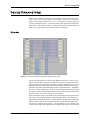
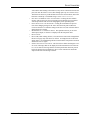
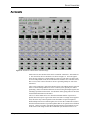
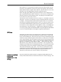
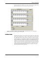
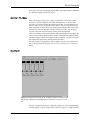
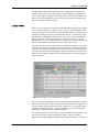
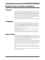
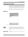
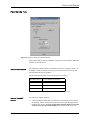
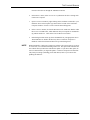
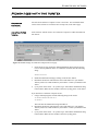
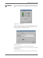
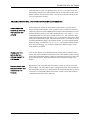
Conference Composer
User Guide
Copyright © 2001 Polycom, Inc. All rights reserved. Printed in the United States of America. Because of technical
progress, specifications are subject to change without notice.
The Polycom logo and Vortex® are registered trademarks of Polycom, Inc..
Polycom, Inc.
Installed Voice Business Group
1720 Peachtree Street NW, Suite 220
Atlanta, GA 30309-2439
Phone: (800) 932-2774, (404) 892-3200
Fax: (404) 892-2512
www.aspi.com
Technical Support:
(800) 932-2774
[email protected]
CCUG-0100-01
CONFERENCE COMPOSERTM USER GUIDE
Conference ComposerTM Software ..............................................................2
Introduction ............................................................................................................ 2
Installation.............................................................................................................. 2
Features of the Conference Composer Window ..................................................... 3
Operating Conference Composer...................................................................5
Device Parameters .........................................................................................8
System ..................................................................................................................... 8
Options.................................................................................................................... 9
Mic/Line Inputs....................................................................................................... 11
Input Filters ............................................................................................................ 12
Automixer................................................................................................................ 13
EF Bus .................................................................................................................... 14
Matrix Mixer........................................................................................................... 15
Output Filters ......................................................................................................... 17
Outputs.................................................................................................................... 17
Logic Input.............................................................................................................. 18
Logic Output ........................................................................................................... 19
Presets..................................................................................................................... 20
Macros .................................................................................................................... 20
Diagnostics ............................................................................................................. 20
Project Files and Creating Reports ................................................................21
File Saving .............................................................................................................. 21
File Restoring ......................................................................................................... 21
Creating Reports..................................................................................................... 21
The Console Window ....................................................................................22
Console Tab ............................................................................................................ 22
Properties Tab ........................................................................................................ 23
Modem Use with the Vortex..........................................................................25
Troubleshooting the Vortex Modem Connection.................................................... 27
Polycom, Inc., Copyright 2001
Technical Support: 800.932.2774
1
CONFERENCE COMPOSERTM SOFTWARE
CONFERENCE COMPOSERTM SOFTWARE
INTRODUCTION
Conference Composer is the design and configuration software that is supplied with
the Vortex®. Its purpose is to make it easy and intuitive to configure Polycom’s Vortex products, share configuration files, create presets, macros, and logic assignments.
Conference Composer operates under Windows™ 98, ME, NT, and 2000.
INSTALLATION
Insert the Conference Composer disk into your CD-ROM drive and run the Setup
program. If you have a previously installed version of Conference Composer on your
computer, it is highly recommended that you uninstall that version (use Add/
Remove Program from the CONTROL PANEL window) before installing the latest
version.
After running the Setup program, simply follow the instructions for installing Conference Composer.
USING CONFERENCE
COMPOSER WITH A
VORTEX AND EF200
PHONE ADD
When using the Conference Composer software with the Vortex and the EF200, plug
the RS-232 into the Vortex. If you plug into the EF200, you may not be able to get
Level information because the EF200 will not know how to interpret the data from the
software that will display metering information.
Conference Composer User Guide
2
Technical Support: 800.932.2774
CONFERENCE COMPOSERTM SOFTWARE
FEATURES OF THE CONFERENCE COMPOSER WINDOW
4
1
3
2
Figure 1. Feauters of Conference Composer window
1.
2.
3.
4.
© Polycom, Inc.
EXPLORER MENU. The Explorer-type menu structure allows you to easily navigate and browse through your device list. Clicking on an item in the tree will display the parameter page to the right of the explorer menu.
STATUS METER. This meter and status light shows the communication status
between your PC and a Vortex or EF device (EF200 or EF1210). The WAITING
light turns yellow when it is communicating via RS-232 with a Vortex or EF
device and the meter indicates how full the command buffer is with commands
being sent to the device.
DSP LOAD. Indicates the current percentage of used available variable DSP
resources.
MENUS.
• FILE. The File menu allows you to create a new Project, Device Chain, or
Device; manages file functions of a Project such as Opening, Saving, or
Closing; and handles printing and Preferences.
• PROJECT. The Project menu contains 3 options: AUTOSCAN, SAMPLE, or
ONLINE. AUTOSCAN finds all Vortex or EF devices connected to the PC and
scans in their settings. SAMPLE loads a sample project into Conference
Composer. ONLINE allows you to either download settings from a Vortex or
EF device or upload settings to a Vortex or EF device.
3
Conference Composer User Guide
CONFERENCE COMPOSERTM SOFTWARE
•
•
Conference Composer User Guide
USER MODE. User mode selects between BASIC and ADVANCED. Basic
mode limits user options that can be adjusted. Advanced mode allows control of all parameters available on Conference Composer.
HELP. The Help menu contains the ABOUT option that shows the version
number of the software.
4
Technical Support: 800.932.2774
OPERATING CONFERENCE COMPOSER
OPERATING CONFERENCE COMPOSER
Conference Composer may either be operated online or off-line (not connected to a
Vortex or EF device) depending on how you would like to use it. If you work off-line
it is easy to save the settings to a file, share the files with others, and then upload the
settings into an EF device when you go online. The online or off-line operation of
Conference Composer is the same, although if you are operating off-line you will
need to add devices to the project before you can start working with the devices.
Conference Composer organizes your projects into a hierarchy of PROJECT, DEVICE
CHAIN, and DEVICE. Starting from the bottom of the list, a DEVICE is simply that –
some piece of equipment that will be used in the installation. A DEVICE CHAIN is a
collection of devices that are linked together through the ASPI Bus or EF Bus (that’s
where the name device chain comes from). Typically these represent all the devices
that are tied to a particular serial port on your computer/controller. The PROJECT represents a collection of DEVICE CHAINS. You can think of the PROJECTS as directories,
the DEVICE CHAINS as files and the DEVICES as items in the files.
There are many different buttons and knobs that allow the user to change settings on
the device. Conference Composer’s convention is that a feature associated with a button is enabled when the button’s LED is lit. To use a knob, click on the knob and
while holding down the mouse button, raise or lower the cursor to increase or
decrease the knob value..
Figure 2. To increase the level, click on the knob and move the cursor UP. To
decrease the level, click on the knob and move the cursor DOWN.
ONLINE: CONNECTED
TO AN EF DEVICE
© Polycom, Inc.
To operate online, the EF Device should be connected to an RS-232 port of your host
computer. The first step is to have Conference Composer scan your EF Device -- this
ensures the settings you see on the PC screen are exactly the settings in the device. To
do this, select the AUTOSCAN option from the PROJECT menu as shown in Figure 3.
This ensures the settings you see on the PC screen are exactly the settings in the
device.
5
Conference Composer User Guide
OPERATING CONFERENCE COMPOSER
Figure 3. Select AUTOSCAN to have Conference Composer automatically find
online devices.
NOTE
If you have any devices currently using the serial port on your PC, such as a PalmPilot’s HotSync, please close those programs to free the COM port before running
AUTOSCAN.
AUTOSCAN will automatically find all EF devices (EF2280, EF1210, EF200) attached
to the RS-232 port and then automatically download all the settings into Conference
Composer. Once the settings have been downloaded to the PC, any changes you
make to the device through Conference Composer will be sent automatically to the
device, updating its configuration in real-time.
Once Conference Composer has finished downloading the settings from the connected devices, you will see the Navigation area look like Figure 4. The amount of
time it takes to sync with the Vortex depends on the number of presets that have valid
data. More presets means more data must be sent to the PC.
Figure 4. Project generated when connected
to a Vortex.
OFF-LINE: OPERATING
WITHOUT AN EF
DEVICE
To operate without any devices connected to the computer you can select NEW>DEVICE->EF2280 to create a sample Vortex system to configure. This will automatically create a Project. Once you have a Vortex installed, your navigation tab should
Conference Composer User Guide
6
Technical Support: 800.932.2774
OPERATING CONFERENCE COMPOSER
look like Figure 4 (the red X’s indicate that you are offline), and you are ready to proceed to the next section.
Figure 5. Operating Conference Composer Offline.
© Polycom, Inc.
7
Conference Composer User Guide
DEVICE PARAMETERS
DEVICE PARAMETERS
Each device in Conference Composer is represented by a list of sub-entries for that
device. For the Vortex, those fields are SYSTEM, MIC/LINE INPUTS, etc. as shown in
Figure 4. By clicking on the Device (EF2280:00 in Figure 4) you bring up the SYSTEM page as shown in Figure 6. Notice that each SYSTEM page has tabs corresponding to the list of sub-entries in Figure 4. Clicking on either a tab or the field name will
bring you to a page with specific controls for that set of functions.
SYSTEM
Figure 6. Vortex System tab shows the block diagram of the device.
The SYSTEM Page presents you with a block diagram of the Vortex. It allows you to
quickly enter text labels for inputs and outputs (this can also be done on all the other
pages too), and see the signal flow from inputs to outputs. Holding the cursor over a
particular block in the block diagram will show signal flow information from inputs
to outputs or outputs to inputs depending on where you hold the mouse. By holding
the cursor over any output block, you can see the all the inputs that map to the particular output. You may enable/disable specific features by left clicking on the blocks in
the SYSTEM Page. If a block is grayed out, it is turned off.
When connected to a device, the Signal Activity LEDs mapped to the inputs and outputs of the SYSTEM Page (See Figure 7) show the signal activity. This indicator is
independent of the gating indicators -- it simply indicates when the input or output has
signal level above the Activity Threshold. The Activity Threshold for what constitutes activity is set on the OPTIONS Page -- it is in the MISCELLANEOUS section. If you
set this level too high, the threshold may be too high and the signal activity LED will
Conference Composer User Guide
8
Technical Support: 800.932.2774
DEVICE PARAMETERS
be difficult to light. If you set the signal activity level too low, the ambient room
noise may light the signal activity LED too easily.
Figure 7. Signal Activity LED of Inputs and Outputs.
The ability to follow signal flow and the Signal Activity LED can provide useful tools
to ensure that the proper input to output mappings have been setup.
OPTIONS
Figure 8. Options Tab.
The OPTIONS tab allows the user to set the following parameters:
•
© Polycom, Inc.
MODEM INITIALIZATION STRING. The modem initialization string, if enabled,
9
Conference Composer User Guide
DEVICE PARAMETERS
•
•
•
•
•
•
will send the desired string to the modem (or any device connected to the RS-232
port) each time the Vortex is reset (either through power-up or a software reset).
This allows the Vortex to put the modem into an Auto Answer Mode, and set the
baud-rate to 9600 bps. The default string is set to: ATE0F1&B1S0=2.
NON-VOLATILE MEMORY LOCK AND PASSWORD. Locking the Non-Volatile
memory will prevent users from overwriting presets that have been saved and
will also prevent the end user from changing the power up default preset.
FRONT PANEL LOCK AND PASSWORD. Locking the Front Panel will prevent
users from changing settings of the Vortex from the front panel LCD menu.
Users will be able to see what the settings in the device are, but will not be able to
change the device settings.
METER DISPLAY ON THE FRONT PANEL. This parameter allows you to select
which input, output, or reference is displayed on the front panel meter.
DEVICE NAME.
DEVICE ID (when working off-line). The Vortex Device ID can be changed from
the OPTIONS page only if the device is off-line. To change the Device ID of an
online Vortex, you should change the Device ID from the front panel LCD menu
and then AUTOSCAN again.
SCREEN SAVER TEXT AND OPTIONS. The Screen Saver allows the designer to create 4 sets of messages that can be displayed on the Front Panel LCD on the Vortex. START TIME is how long after the last front panel button has been pressed
before the messages begin displaying. DELAY TIME controls how much time
elapses before the next message is shown.
Conference Composer User Guide
10
Technical Support: 800.932.2774
DEVICE PARAMETERS
MIC/LINE INPUTS
Figure 9. Vortex MIC/LINE INPUTS tab showing Mic/Line Input 1, Line Input A,
and the Signal Generator.
The MIC/LINE INPUTS page contains all the controls required to configure the 12
inputs (8 mic/line inputs and the 4 line level inputs). Figure 9 shows a Mic/Line Input
channel, a Line Input channel, and the Signal Generator – note that you can enable/
disable an input from view with the numbered buttons on the top of the page. Once
Input 1 is configured, the user may copy those settings to the other mics by clicking
the COPY SETTINGS 1–8 button. The same capability exists to copy the settings from
Input A to the remaining line level inputs.
The fields for Inputs 1-8 are as follows:
•
•
•
•
•
© Polycom, Inc.
TEXT BOX. This stores up to 16 character for the input label.
GATE LED. This LED is active if the LEVELS button is enabled and the particular
input gates on.
METER PER INPUT. This shows the signal level if it is between -20dBu and
+20dBu.
GAIN SLIDER AND TEXT BOX. These allow the user to set the input gain in dB on
the channel. The value adds gain in the analog domain using digitally controlled
trimpots. For Inputs 1-8, the gain slider can provide up to 30dB of gain. For
Inputs A-D, the gain slider can provide up to 20dB of gain.
MIC/LINE SWITCH. This applies mic or line level gain to the Input. In Mic mode,
11
Conference Composer User Guide
DEVICE PARAMETERS
33dB of gain is added to the signal.
PHANTOM POWER. 24 V phantom power can be enabled or disabled (it is enabled
in Figure 9).
• MUTE. This button is used to mute or unmute the input signal (MUTE is disabled
in Figure 9).
• AGC ENABLE. This will enable/disable the automatic gain control (AGC).
• AGC MAX GAIN. This can be used to limit the total amount of gain the AGC can
apply to the signal.
• AGC MIN GAIN. This can be used to limit the total amount of attenuation the
AGC can apply to the signal. For example, setting the AGC MIN GAIN to -10 dB
will keep the AGC from attenuating the signal too much if someone taps on the
microphone.
• AGC RATE. This limits the rate of change of the AGC from between 1 to 5 dB/
sec.
• AEC ENABLE. This will enable or disable the acoustic echo canceller (AEC)
(AEC is enabled in Figure 9). If enabled the user can select the reference signal
to use either REF 1, REF 2, or the BUS REFERENCE.
• SUPPRESION. The user can also control the amount of suppression that is applied
by the echo canceller during a double-talk situation. Suppression ranges from
NONE (no suppression) to YIKES! mode (half-duplex).
• NC ENABLE. This will enable/disable noise cancellation (NC). If enabled, the
user can select the amount of noise cancellation using NC LEVEL. NC LEVEL
ranges from 0 to 15 dB of cancellation.
The controls for the line level Inputs A-D are simpler than the mic/line inputs. The
user can select a Gain (0dB is the default) and enable/disable Mute.
•
The SIGNAL GENERATOR input allows the user to create a noise source (either pink or
white noise) for use with noise masking applications or calibration of the Vortex.
INPUT FILTERS
Each of the inputs can have up to 5 filters of equalization. These filters include Parametric, Low Pass, High Pass, Low Shelf, and High Shelf. To use the filters, select the
type of filter and adjust the controls for the filter. You can adjust the controls in a
variety of ways: by typing in values in the text boxes, using the cursor up/down, using
Page Up/Page Down, or by clicking and holding the knob and moving the mouse up
to increase the value or down to decrease the value. The frequency response of the
plots may be viewed by clicking on the GRAPH button.
The ENABLE button per filter enables/disables that particular filter on the Input. The
ENABLE FILTERS button enables/disables all filters on the particular Input Channel.
This button toggles with the Filter Bypass buttons per Input. All filters for a particular input can be bypassed by clicking on the BYPASS button for that channel.
Once the settings are configured for Input Channel 1, the user may copy those settings
to all other channels using the COPY CHANNEL 1 FILTERS TO ALL CHANNELS button.
Conference Composer User Guide
12
Technical Support: 800.932.2774
DEVICE PARAMETERS
AUTOMIXER
Figure 10. Automixer controls on the Automixer Page.
Each Vortex has two automixers that can be controlled: Automixer 1 and Automixer
2. The controls for the two automixers are shown in Figure 10. For most applications, the user will choose a single automixer. However if the Vortex is split to operate in two independent rooms, the second automixer should be used. The HOLD TIME,
DECAY TIME, and CAMERA THRESHOLD TIME is specified globally for each of the
automixers.
The CAMERA THRESHOLD TIME is the amount of time a microphone must be gated on
before a Camera Gating Indicator is sent to a control system, possibly for camera
positioning. Please note that the automixers do not sum the gated inputs together, the
summing is performed in the matrix - the automixer makes gating and level decisions
and sends that information to the matrix.
The LOCAL MAX NOM can be set to limit the maximum number of open microphones that can be open at a given time on the local Vortex. In single Vortex applications, this is the only control required to limit the number of open microphones.
When multiple Vortexes are linked together, the GLOBAL MAX NOM can be used to
limit the maximim number of open microphones that can be opened across all linked
Vortexes. Unless you want to specifically limit the number of microphones in a particular Vortex when using GLOBAL MAX NOM then you should leave the LOCAL
© Polycom, Inc.
13
Conference Composer User Guide
DEVICE PARAMETERS
MAX NOM set to 8. To link Vortexes together, use the BUS MIXER number. Put all
the Vortexes you would like to operate as one large mixer together on the same BUS
MIXER number with the exception of BUS MIXER 0. If the BUS MIXER is set to 0, the
Automixer will work independently from other connected Vortexes.
Each of the eight signal channels going into the automixer can be configured to be
part of a particular automixer (Mixer 1 or Mixer 2). If set to NONE, it is not part of an
automixer and does not affect gating decisions. The gating for each channel can be
set to to FORCE ON, FORCE OFF, or AUTO.
The THRESHOLD TYPE can either be ADAPTIVE or MANUAL. The default is ADAPTIVE
THRESHOLD. The ADPATIVE THRESHOLD can be set when the THRESHOLD TYPE is set
to Adaptive. This represents how much louder the signal needs to be over the noise
floor before the microphone should be gated on. MANUAL THRESHOLD allows you to
set an absolute threshold that the signal needs to be greater than in order to gate on.
GATE PRIORITY can be configured for each microphone. Priority 1 is the highest priority and Priority 4 is the lowest priority. A higher priority input takes precedence
over a lower priority input if the maximum number of open microphones (Max NOM)
is set to be less than the number of microphones assigned to that automixer.
EF BUS
The EF BUS page allows the user to configure how to combine the bus signals from
the other linked Vortexes and control which echo canceller reference is sent to other
devices as the Bus Reference. Since there can be up to 8 Vortexes linked together and
each device can put 4 different signals on the bus (W, X, Y, and Z), there are 4 submatrices to allow flexibility in how the signals from other devices get mixed together and
get presented to the main matrix. Figure 11 shows the EF BUS submatrix and the fact
that there are 4 submatrices and the inputs are WB0, … WB7 for the W bus, XB0, …,
XB7 from the X bus, and the same for the Y and Z busses. The cross points can be
changed by left clicking on the cell and adjusting the gain. Cross points can be muted
by right-clicking on the cell (an unmuted crosspoint is indicated by a bolded black
value; muted is indicated by a gray value). Any of the rows of the matrices can be
configured as a mix-minus which allows the user to work with a simple mix-minus
sum of all the other devices. If more complicated mixing from other devices is
required, any of the matrix rows can have arbitrary cross points gains.
EXPORTING THE ECHO
CANCELLER
REFERENCE ON THE
EF BUS
You can set which echo canceller reference is assigned as the Bus Reference to be
used by all other linked Vortexes in the EXPORTED SIGNALS section on the page. The
Conference Composer User Guide
14
Technical Support: 800.932.2774
DEVICE PARAMETERS
choices are REFERENCE 1, REFERENCE 2, or NONE. Only one Vortex can put an AEC
Reference onto the Bus. The other Vortexes can use this reference.
Figure 11. The EF BUS sub matrix. In this example, WB0 is grayed out because we are working with
Device 0. Any of the cross points can have arbitrary gains.
MATRIX MIXER
The Matrix Mixer in Figure 12 allows the user to map any input to any output with an
arbitrary gain in dB applied from -100 dB to +20 dB. Muted cells are shown in light
gray while unmuted cells are shown in bold. To set the gain of a single cross point,
“left” click on the cell. To set the gain of a collection of cross points click and drag to
select a rectangular area. A slider control with a text box will appear to allow you to
change the gain, select mute/unmute, or, on Inputs 1-8, choose the gated version of
the Input. If you are using signals for reinforcement and specifically want the gated
signals at an attenuated level, then set the gated crosspoint to the desired level such as
-15 dB. In general, the gain of gated signals should be set to 0 dB since the matrix
will sum the automixed signals and use the appropriate weightings of the signals
based on the information from the automixer.
© Polycom, Inc.
15
Conference Composer User Guide
DEVICE PARAMETERS
To change the gain of an entire row or column you may simply click on the column or
row header (any of the labels 1-D on the columns or the rows) to see a collection of
sliders as shown in Figure 13.
Figure 12. The full cross point matrix for a system using a phone add, a codec,
and stereo program audio. Only the bold crosspoints are unmuted.
Figure 13. Cross point slider view of how Input A is used in all the output channels.
The outputs R1 and R2 correspond to the echo canceller references REF 1 and REF 2.
While these outputs are not physical outputs on the product, they allow you to build
the echo canceller reference without using physical outputs from the device. In the
example in Figure 12, we used stereo program audio and consequently had a local left
output (Output C) and a local right output (Output D) in the room. The echo canceller
reference R1 included both the codec audio (Input A), the phone add audio (Input B)
Conference Composer User Guide
16
Technical Support: 800.932.2774
DEVICE PARAMETERS
and a mono mix of the left and right program audio. The program audio is attenuated
by 3 dB before adding it into the R1 output.
OUTPUT FILTERS
Each of the outputs can have up to 5 filters of equalization. These filters include
Parametric, Low Pass, High Pass, Low Shelf, and High Shelf. To use the filters,
select the type of filter and adjust the controls for the filter. You can adjust the controls in a variety of ways: by typing in values in the text boxes, using the cursor up/
down, using Page Up/Page Down, or by clicking and holding the knob and moving
the mouse up to increase the value or down to decrease the value. The frequency
response of the plots may be viewed by clicking on the GRAPH button.
The ENABLE button per filter enables/disables that particular filter on the Output. The
ENABLE FILTERS button enables/disables all filters on the particular Output Channel.
This button toggles with the Filter Bypass buttons per Output. All filters for a particular output can be bypassed by clicking the BYPASS button.
Once the settings are configured for Output Channel 1, the user may copy those settings to all other channels using the COPY CHANNEL 1 FILTERS TO ALL CHANNELS
button.
OUTPUTS
Figure 14. Output control for each of the 12 output channels is available on the
Outputs Tab. Channels can be hidden from view from the VIEW OUTPUTS control.
The OUTPUTS page allows the user to adjust the output level, select NOM attenuation,
and mute outputs. A typical output control is shown in Figure 14. NOM attenuation
© Polycom, Inc.
17
Conference Composer User Guide
DEVICE PARAMETERS
(labelled NOM) enabled will reduce the gain of the output signal by 3dB for each
doubling of the number of open microphones. NOM attenuation is computed separately for each output, depending on the inputs that are used to build each output. The
output levels will be displayed in real-time if the LEVELS function is enabled (click
the LEVELS button to enable the levels).
LOGIC INPUT
The LOGIC INPUTS page allows the user to assign individual logic input pins to trigger
specific functions, macros, or complete presets. The types of functions that can be
executed include any function that can be controlled with an RS232 command such as
changing or ramping gains, muting, enable/disable the AEC, set AEC Mode, choose
AEC Reference, enable/disable AGC, set AGC Max, set AGC Rate, enable/disable
Noise Cancellation, set Noise Cancellation Level, set Mic or Line Level, or turn
Phantom Power On or Off. Within Conference Composer, the Logic pins also have an
LED associated with them to indicate the status of the contact closure.
A logic pin can have one of the following states: unassigned, assigned to a particular
function, macro, or preset, or assigned to one of four groups. To assign a function to a
pin, single click and hold on the pin of the connector and select a colored assignment
of the pin from the colored boxes that appear. Figure 15 shows the selection process –
match the colors with the legend to create an assignment entry for either the single pin
or the logic group.
Figure 15. Selecting a type of assignment for a logic pin
Once a pin has been assigned, there are three states associated with the pin: activated,
deactivated, and held. To assign a function to one of these three states, right click in
the cell, and then pick the function off the list. Alternatively you can type the associated RS232 command in directly. Clicking the SHOW ACTUAL COMMAND button
translates the command to the actual RS232 command.
You can also change the polarity of the pin by right clicking on the pin number. This
will cause an underline to appear under the pin number. When the polarity is
changed, what normally happened when the command was activated (i.e., contact was
Conference Composer User Guide
18
Technical Support: 800.932.2774
DEVICE PARAMETERS
closed) will happen when the contact is open. The LED status will also update to
reflect polarity status.
Figure 16 shows an assignment of Pin 1 to mute Input 1 when active (i.e., the contact
closed) and to unmute when inactive (contact open)..
Figure 16. Logic pin 1 is assigned to mute input 1 when activated and unmute when deactivated.
LOGIC OUTPUT
The LOGIC OUTPUT page allows the user to assign a status function to one of the 20
logic status outputs. The status functions could include AEC On or Off, AGC On or
Off, NOM Attenuation, Camera Gating, Gating, Mic or Line Level, Muting, Noise
Cancellation, and Phantom Power On or Off. To assign a status function to the status
pin, click on the pin. This will enable the ACTIVATED and DEACTIVATED control windows. Right click in the ACTIVATED or DEACTIVATED field to pick a status off the
menu list, or type the command in directly. As with the Logic Input pins, the SHOW
ACTUAL COMMAND button will show the command syntax.
To create status output that is a logical combination of particular inputs or outputs, use
the logical syntax (+, 0, or 1). For instance, to create a status output that will be set
when Input Channels 1 AND 3 are muted, the syntax is ’MUTE*1.1.....’. To
create a muting status output that will be set when Input Channels 1 OR 3 are muted,
the syntax is ’MUTE*+.+.....’. Notice that the MUTE* status command can take
up to 12 arguments, one for each input. The gating status command GATE* takes 8
arguments since only Inputs 1-8 can be gated.
The polarity of the outputs can also be changed by right-clicking on the pin number.
© Polycom, Inc.
19
Conference Composer User Guide
DEVICE PARAMETERS
PRESETS
The Vortex supports 16 factory presets (meaning they can’t be overwritten by the
user) and 32 user presets. These presets store all information about the settings for
the device: input gains, matrix crosspoints, automixer settings, etc. Everything.
Changes to the device’s settings are not automatically saved in the preset -- you must
save your changes to the preset by clicking on the SAVE button. Each preset can have
a 16 character label. The user can SAVE the current settings as a preset at any time or
RESTORE a different preset at any time. Restoring a preset will send all the status
messages to the RS-232 interface so an attached control panel will remain synchronized with the device. The user may also configure which preset is used when the
device powers up using the POWER ON PRESET parameter at the top right of the page.
The DELETE button can be used to erase a preset.
MACROS
You can create up to 256 macros. Each macro can have up to 256 single commands
that are executed sequentially when the macro is executed. The user selects a macro
to create and then sequentially puts the commands into the macro.
New commands may be inserted into the macro after the existing command by right
clicking on an existing command and selecting either a command off the list or the
INSERT COMMAND option which will let you type a command in directly. You can
also add new commands to the macro by typing the RS-232 command strings directly
into the text box.
To change the order of the command in the macro, choose either MOVE COMMAND
UP or MOVE COMMAND DOWN. Use DELETE COMMAND to delete a command and
DELETE ALL COMMANDS to delete all commands from the current macro. CLEAR
MACRO will erase all commands from a macro and CLEAR ALL MACROS will delete
all commands and macros.
DIAGNOSTICS
The DIAGNOSTICS page allows you to adjust Gain levels and enable/disable Mute on
Inputs 1-8, A-D and Outputs 1-8, A-D. On Input 1-8, you can also check the status of
gating, AEC state information (shown by the LEDs marked XMIT and RECV), AGC,
and Room Gain as well as enable/disable AGC and Noise Cancellation. Levels of the
echo canceller References, R1 and R2 are also displayed on this page.
To turn on the meter information, select the LEVELS button.
Conference Composer User Guide
20
Technical Support: 800.932.2774
PROJECT FILES AND CREATING REPORTS
PROJECT FILES AND CREATING REPORTS
FILE SAVING
When working off-line, you may find it useful to save Project files for archival purposes or to allow you to send the configuration to another person. To save a Project
file, either left click on the Project and then right click to select SAVE or from the FILE
menu, select SAVE PROJECT. Once you enter a file name, you can save the selected
Project to disk. A Project file includes all the devices that make up the project. For
instance if you have a Project that includes multiple Vortexes and an EF200, then the
Project file that is saved to disk will include settings for all the devices. To save the
file to a different name, select SAVE AS from the FILE menu.
Presets for the devices in the Project are also stored to the file when working off-line.
FILE RESTORING
You can easily restore the settings from a file to actual EF devices. To restore a
Project, first open the Project from the FILE menu. Then when connected to the EF
Devices, left click on the Project and select the ONLINE button. This will present a
window with the following options: DOWNLOAD SETTINGS FROM THE DEVICE,
UPLOAD SETTINGS TO DEVICE, or CANCEL. Select UPLOAD SETTINGS TO DEVICE to
upload the Project settings to the device.
You should set the Device IDs on the actual devices to match those in the project
before uploading the Project.
Once uploading has started, the display will present a status bar of the progress of
uploading. All Presets in the Project will be uploaded along with Project settings.
CREATING REPORTS
Conference Composer can automatically generate reports of a Project, Device Chain,
or Device which show all the settings configured for the device. A Project report will
consist of the device chains and any devices that are part of the device chain. A device
chain report will only include the devices included in the device chain. A device
report only includes the settings for that particular device.
Once a report has been selected, the system prompts for whether all the presets should
be included in the reports. Select Yes if you would like all the presets to be included
in the reports. Select No if you do not want the preset information to be included in
the report. In this case you will only report the current operating settings of the
device.
Reports may be customized by allowing you to put in a company name and address
information. You can enter this information by selecting the Project and type Report
tab.
To print the report, you have the option to print directly to a printer and/or to create a
Portable Disk Format (PDF) file.
© Polycom, Inc.
21
Conference Composer User Guide
THE CONSOLE WINDOW
THE CONSOLE WINDOW
The Console Window provides communication information between your PC and the
EF Device. There are two tabs in this window: the Console Tab and the Properties
Tab. The Console Tab is a terminal program that allows you to send commands to the
EF Device and monitor the acknowledgements. The PROPERTIES Tab allows you to
change the settings on flow control and also includes the capability to update firmware.
To open a Console Window, right click on the COM port in Conference Composer’s
Explorer menu, and choose CONSOLE from the pull down menu that appears.
CONSOLE TAB
Figure 17. Console Tab.
WATCHING
COMMANDS
The larger window in the Console Tab displays communications between your PC
and the EF Device. Strings that are shown in blue text indicate a string sent by the
PC. Strings shown in red text are acknowledgements sent by the EF Device.
This tool is a good way to monitor communication between control systems and the
EF Devices.
SENDING COMMANDS
The small rectangular box at the bottom of the Tab is for typing in commands to send
to the EF Device.
Conference Composer User Guide
22
Technical Support: 800.932.2774
THE CONSOLE WINDOW
PROPERTIES TAB
Figure 18. Properties Tab in the Console Window.
The Properties Tab provides the capability to change flow control and also update the
firmware of your EF Device.
UPDATING FIRMWARE
The capability to update firmware is included in Conference Composer version 1.62
and higher. Check our website at www.aspi.com for the latest versions of the software and information on our products.
The latest EchoFree firmware versions are listed below in Table 1.
ECHOFREE DEVICE
LATEST FIRMWARE VERSION
EF2280 Vortex
version 1.18
EF1210
version 1.05
EF200
version 1.13
Table 1: Latest firmware versions of EchoFree devices as of 11/15/01.
UPDATE YOUR EF
DEVICE
© Polycom, Inc.
In Conference Composer software,
1.
Connect the RS-232 cable from your computer to the EchoFree device that you
are updating. Ensure that your serial port cable is wired with RTS and CTS for
hardware flow control. If you do not have RTS and CTS, this process will not
work and error messages will be displayed. You can keep the device con-
23
Conference Composer User Guide
THE CONSOLE WINDOW
nected to other devices through the ASPI Bus or EF Bus.
NOTE
2.
In the PROJECT menu, select AUTOSCAN to synchronize the device settings with
Conference Composer.
3.
Open a CONSOLE window by right-clicking on the Serial Port connected to your
EchoFree device in the Explorer type menu on the left side of the Conference
Composer window. Choose CONSOLE from the menu that appears.
4.
In the CONSOLE window, click on the PROPERTIES tab. Make sure that the ASPI
DEVICE FOUND LED is blue, which indicates that your computer is communicating with the EF device. Click on the UPDATE MICROCODE button.
5.
In the dialog box that comes up, choose the EFB file for your appropriate device.
These EFB files are found in the directory where Conference Composer is
installed. Follow the instructions that come up in the dialog boxes.
When prompted by Conference Composer to perform a STANDARD UPDATE or THOROUGH UPDATE, we recommend choosing THOROUGH. This option will reinitialize the
non-volatile memory both before and after the update. If you choose this option, be
sure to Autoscan before you begin the update. Conference Composer will automatically load your settings (including presets and macros) back to your Vortex after
updating the firmware.
Conference Composer User Guide
24
Technical Support: 800.932.2774
MODEM USE WITH THE VORTEX
MODEM USE WITH THE VORTEX
CONFERENCE
COMPOSER
You will need Conference Composer version 1.62 or later. You can find the latest
version of the software on our website at www.aspi.com, on the Vortex page.
ON SITE WITH THE
VORTEX
At the local site with the Vortex, use Conference Composer to enable the modem to
auto answer:
Figure 19. Modem settings on Conference Composer OPTIONS page.
1.
On the OPTIONS page, choose the default initialization string from the INITIALSTRING pull-down menu. If a default is not listed, enter the following
string:
IZATION
ATE0F1&B1S0=2
2.
3.
4.
Enable the initialization string by clicking on the ENABLE button.
Disconnect the RS-232 cable from the Vortex and connect it to your modem.
You may need to use a null modem for your modem. Connect your modem to the
Vortex.
Cycle power on the Vortex. As it powers up, it will send the initialization string
to the modem. Make sure the modem is On before cycling power on the Vortex.
If you don’t have Conference Composer on site,
1.
2.
3.
© Polycom, Inc.
Using a terminal program, send the following strings to the Vortex:
F**MINISTRATF1E0&B1S0=2
F**MINI1
This will enter the initialization string and enable it.
Disconnect the RS-232 cable from the Vortex and connect it to your modem.
You may need to use a null modem for your modem. Connect your modem to the
Vortex.
Cycle power on the Vortex. As it powers up, it will send the initialization string
to the modem. Make sure the modem is On before cycling power.
25
Conference Composer User Guide
MODEM USE WITH THE VORTEX
FROM THE REMOTE
SITE
At the remote site, open Conference Composer and from the FILE menu choose PREFERENCES. The dialog box that comes up should look similar to the one below in Figure 20.
Figure 20. FILE -> PREFERENCES
Find the Comm Port that your modem is connected to and make sure the box beside it
is checked. Click on the corresponding SETTINGS button. In the dialog box that
comes up, go to the MODEM tab (see Figure 21 below).
Figure 21. Modem tab
If the modems hang up before you connect, increase the TIMEOUT time.
Choose the default string in the INITIALIZATION STRING pull down menu. It should be
the following string:
AT F1 E0 Q0 V0 &K3 &D0
Click on the box beside USE MODEM to enable it. Then enter in the phone number.
Conference Composer User Guide
26
Technical Support: 800.932.2774
MODEM USE WITH THE VORTEX
After both sides are setup, you should be able to AUTOSCAN from the remote end.
Autoscanning will have your modem dial the remote site and connect to the remote
modem, which is connected to the Vortex. You can then control the Vortex just like
you were connected to it locally.
TROUBLESHOOTING THE VORTEX MODEM CONNECTION
VERIFY THAT THE
VORTEX IS SENDING
THE CORRECT INIT
STRING
MAKE SURE THE
INITIALIZATION
STRING IS SENT TO
THE MODEM
DOUBLE CHECK THE
CABLE BETWEEN THE
MODEM AND THE
VORTEX
© Polycom, Inc.
On the Vortex side, connect the Vortex RS-232 port to the PC (you may need to
remove the null modem adapter). Next, open the CONSOLE window in Conference
Composer (right-click on the COMM port in the Explorer menu and choose CONSOLE
from the pull down menu) or some other terminal program. Now, send a F**PING
command and make sure the Vortex responds with a PONG. This verifies the cable
connection between the PC and the Vortex. Now, cycle the power on the Vortex while
leaving the terminal window open. When the Vortex reboots, you should see it send
the modem initialization string to the terminal window. If you are using the default
modem init string, you should see ATE0F1&B1S0=2 echoed in the terminal window.
If you don’t see the string, you will need to double check that the string is set correctly and that it is enabled.
If you are sure that the correct modem init string is being sent out when the Vortex
reboots, then connect the RS-232 cable between the Vortex and the modem (you may
need to add a null modem adapter). Make sure the modem is powered on, then cycle
the power to the Vortex. This ensures that the Vortex sends the init string to the
modem.
Depending on your serial cable and your modem, you may or may not need a null
modem adapter. The Vortex RS-232 port is configured as a DCE. Most modems are
also configured as a DCE, so you will most likely need a null modem (The serial ports
of most PCs are configured as DTE, which means you don’t need a null modem to
communicate between the Vortex and a PC).
27
Conference Composer User Guide