1
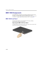
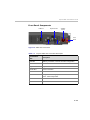
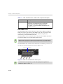
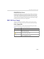
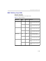
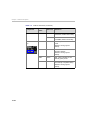
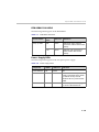
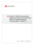
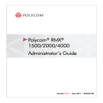
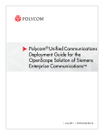
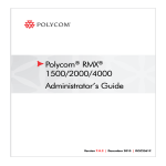
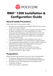
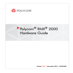
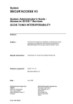
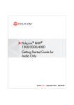
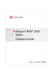
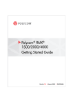
Polycom® RMX® 1500
Hardware Guide
Version 7.0.1 | September 2010 | DOC2557B
Trademark Information
Polycom®, the Polycom “Triangles” logo, and the names and marks associated with Polycom’s
products are trademarks and/or service marks of Polycom, Inc., and are registered and/or
common-law marks in the United States and various other countries.
All other trademarks are the property of their respective owners.
Patent Information
The accompanying product is protected by one or more U.S. and foreign patents and/or pending
patent applications held by Polycom, Inc.
© 2010 Polycom, Inc. All rights reserved.
Polycom, Inc.
4750 Willow Road
Pleasanton, CA 94588-2708
USA
No part of this document may be reproduced or transmitted in any form or by any means,
electronic or mechanical, for any purpose, without the express written permission of Polycom, Inc.
Under the law, reproducing includes translating into another language or format.
As between the parties, Polycom, Inc., retains title to and ownership of all proprietary rights with
respect to the software contained within its products. The software is protected by United States
copyright laws and international treaty provision. Therefore, you must treat the software like any
other copyrighted material (e.g., a book or sound recording).
Every effort has been made to ensure that the information in this manual is accurate. Polycom, Inc.,
is not responsible for printing or clerical errors. Information in this document is subject to change
without notice.
Polycom RMX 1500 Hardware Guide
Table of Contents
Hardware Description . . . . . . . . . . . . . . . . . . . . . . . . . . 1-1
Main Features .......................................................................................... 1-1
RMX 1500 Specifications ....................................................................... 1-2
RMX 1500 System Capacities ................................................................ 1-3
Site Requirements ................................................................................... 1-5
Safety Requirements ...................................................................... 1-5
Rack Mount Safety Precautions .................................................... 1-5
Installation Precautions ................................................................. 1-6
Connecting the RMX 1500 to a Power Source ............................ 1-7
Connecting the RMX 1500 to AC Power ............................. 1-7
Connecting Cables on the RMX 1500 ........................................... 1-8
First-time Power-up ....................................................................... 1-8
RMX 1500 Components ....................................................................... 1-10
RMX 1500 Front Panel ................................................................. 1-10
Opening the RMX 1500 Front Panel .................................. 1-10
Front Panel Components ..................................................... 1-11
RMX 1500 Rear Panel ................................................................... 1-12
RTM IP 1500 .......................................................................... 1-12
RTM ISDN 1500 .................................................................... 1-14
ISDN/PSTN Clock Source .................................................. 1-15
RMX 1500 Power Supply ............................................................. 1-15
Power Supply LEDs ............................................................. 1-15
RMX 1500 LEDs .................................................................................... 1-16
RMX 1500 Front Panel LEDs ....................................................... 1-16
RMX 1500 Rear Panel LEDs ........................................................ 1-17
RTM IP 1500 LEDs ................................................................ 1-17
RTM ISDN 1500 LEDS ......................................................... 1-19
Power Supply LEDs ............................................................. 1-19
Component Installation & Replacement . . . . . . . . . . . . 2-1
Installing the RTM ISDN 1500 Card ............................................ 2-2
Component Replacement ...................................................................... 2-4
Replacing the RTM ISDN 1500 ..................................................... 2-5
i
Table of Contents
ii
1
Hardware Description
This Hardware Guide provides information on the RMX 1500 and its
components. This system utilizes a modular platform, whose
components are designed for high performance, capacity and reliance.
Main Features
The Polycom RMX 1500 offers the following features:
•
Linux® based
•
Chassis based on the ATCA standard
•
Support for standard network interfaces (H.323, SIP video, ISDN,
PSTN and LAN)
•
New hardware technologies
•
Telco grade high availability, on-line upgrading and dynamic
resource allocation
•
Easy integration of conference elements into external network
management
•
Enhanced Continuous Presence (multi-image video)
•
IVR (Interactive Voice Response) module
1-1
Chapter 1-Hardware Description
RMX 1500 Specifications
Table 1-1
Polycom RMX 1500 Specifications
Physical
Height
1U (4.44 cm.)
Width
19” (48.26 cm.)
Depth
23.6” (60 cm.)
Weight
Up to 12 Kg.
Media Protocols
Audio
G.711, G. 719, G.722, G.722.1, G.729A, G.723.1,
Siren14, Siren 22.
Video
H.261, H.263, H.264.
Network Interfaces
IP, ISDN, PSTN and LAN
H.323, SIP, ISDN, PSTN and LAN
Power Supply
AC Input/ Range, BTU
Voltage range: 100-240 VAC ±10%, 47-63 Hz.
Maximum BTU output: 3400 per hour.
Power Consumption
AC Maximum Power
consumption
350 Watts.
Environment
1-2
Operating temperature
0°– 40°C (22°– 104°F).
Storage temperature
-40°– 70°C (-40°– 158°F).
Relative humidity
15% - 90% no condensing.
Operating altitude
Up to 4,500 m (15,000 ft.).
Operating ESD
4 kV.
Polycom RMX 1500 Hardware Guide
RMX 1500 System Capacities
Conferencing Capacities
The following table summarizes the different system capacities.
Table 1-2
System Functions and Capacities RMX 1500
System Functions
Capacity
Maximum number of Video participants in a conference
90
Maximum number of PSTN participants in a conference
120
Maximum number of VOIP participants in a conference
360
Maximum number of Audio calls per second
5
Maximum number of Video calls per second
2
Maximum number of Conferences
400
Maximum number of Meeting Rooms
1000
Maximum number of Entry Queues
40
Maximum number of Profiles
40
Maximum number of Conference Templates
100
Maximum number of SIP Factories
40
Maximum number of IP Services
1
Maximum number of ISDN Services
2
Maximum number of IVR Services
40
Maximum number of Recording Links
20 (default)
Maximum number of IVR Video Slides
150
Maximum number of Log Files (1Mb max.)
4000
Maximum number of CDR Files
2000
Maximum number of Fault Files
1000
Number of Participant alerts
Unlimited
1-3
Chapter 1-Hardware Description
Table 1-2
System Functions and Capacities RMX 1500
System Functions
Capacity
Maximum number of concurrent RMX Web Client
connections to the MCU
20
Maximum number of Users
100
Maximum number Address Book entries
4000
Maximum number of gateway profiles
40
Maximum number of Reservations (Internal Scheduler)
2000
Resource Capacities
Table 1-3
1-4
System Resource Capacities According to Video Resolution
Resource Type/Video Resolution
Resources with MPMx
HD Support
CP / VSW
CIF H.263
60
CIF H.264
90
SD / 4CIF H.264
60
4CIF H.263
30
720p30
30
1080p30fps/720p60
15 (Symmetric)
VSW 2Mb
80
VSW 4Mb
40
VSW 6Mb
20
VOIP
360
PSTN
120
ISDN
60 (at 128 Kbps) - 4 E1/T1
Polycom RMX 1500 Hardware Guide
Site Requirements
This section describes the requirements your site must meet for safe
installation and operation of the system.
Safety Requirements
For your protection, please read these safety instructions completely
before operating the equipment.
•
Look carefully for potential hazards in your work area: moist floors,
ungrounded power cables, frayed power cords, missing safety
grounds and so forth.
•
Locate the main circuit breaker within the room.
•
Locate the emergency power OFF switch within the room.
•
Never assume that power is disconnected from a circuit.
•
Use only the power cord supplied with the system.
•
The power cord should only be connected to a power outlet that has a
protective ground contact.
•
Ensure that the power cord is easily accessible from the back of the
system at all times.
•
Place the equipment in a well-ventilated area where the vents are free
from obstruction.
•
Do not place heavy objects directly on top of the RMX 1500 unit.
•
Do not use liquids around your equipment.
Rack Mount Safety Precautions
The following precautions should be followed with regards to rack mount
safety:
•
Keep the area around the RMX 1500 clean and free of clutter.
•
Decide on a suitable location for the equipment rack that will hold the
RMX 1500 unit. It should be situated in a clean, dust-free area that is
well ventilated. Avoid areas where heat, electrical noise and
electromagnetic fields are generated. You will also need it placed
near a grounded power outlet.
•
Ensure that the leveling jacks on the bottom of the rack are fully
extended to the floor with the full weight of the rack resting on them.
1-5
Chapter 1-Hardware Description
•
In a single rack installation, stabilizers should be attached to the rack.
•
In multiple rack installations, the racks should be coupled together.
•
Always make sure the rack is stable before extending a component
from the rack.
•
You should extend only one component at a time - extending two or
more simultaneously may cause the rack to become unstable.
•
Before you install the rails, determine the placement of each
component in the rack.
•
Install the heaviest components on the bottom of the rack first, and
then work up.
•
Allow the power supply units to cool before touching them.
•
Always keep the rack’s trays and card’s slots closed when not
servicing, to maintain proper cooling.
Installation Precautions
When handling electronic components, standard anti-static precautions must be
observed:
• Wear a grounding strap
•
Handle cards by their edges only and do not touch their components or
connector pins
•
Keep components in anti-static bags, when not installed in the RMX1500
The following precautions should be followed with regards to installation
of the RMX 1500:
•
Use a regulating uninterruptable power supply (UPS) to protect the
RMX 1500 from power surges and voltage spikes, to keep your MCU
operating in case of a power failure.
•
Place the RMX 1500 on a hard, flat surface such as a desktop or mount
it on 19” rack.
•
The airflow of the RMX 1500 is from right to left. Be sure that the
areas in the left and right side of the system are clear for proper
ventilation.
Sealed System! The RMX 1500 is a sealed system, breaking the seal and
opening the RMX chassis VOIDS the WARRANTY!
1-6
Polycom RMX 1500 Hardware Guide
Connecting the RMX 1500 to a Power Source
The following restrictions apply to the conductors and connectors that
may be used to ground the unit when rack mounted:
•
When using bare conductors, they must be coated with an
appropriate antioxidant compound before crimp connections are
made. Tinned, solder-plated or silver-plated connectors do not have
to be prepared in this manner.
•
The same bolt assemblies should not secure multiple connectors.
•
Listed fastening hardware must be compatible with the materials
being joined and must be preclude loosening, deterioration and
electrochemical corrosion of the hardware and joint materials.
Connecting the RMX 1500 to AC Power
•
Do not connect the green or green-yellow wire to the system single-point
ground screw.
•
•
Only the AC Power cable supplied by Polycom should be used.
•
The outlet intended for connecting the power cord must be protected with
an external overcurrent protection device either in building or in the rack
with the rating not higher than 20Amp.
•
Do not use an Extension cord with the cable.
1
The size of the protective earthing conductor should be a minimum of
10AWG.
Make sure that the power button is switched OFF on the RMX 1500.
ON/OFF
button
USB Slot
2
Insert the power cable into the power connector on the rear panel of
the RMX 1500.
1-7
Chapter 1-Hardware Description
Connecting Cables on the RMX 1500
To connect the cables:
• For the RTM-IP 1500 module:
— Connect the Media cable to LAN 2 port.
— Connect the Network cables to the MNG (Signaling) port &
MNGB (Management Network) port.
— (Optional) Connect the Shelf Management cable to the Shelf port.
•
For the RTM ISDN 1500 module:
— Connect the E1/T1 cables to their PRI (1-4) ports.
Power Cable
E1/T1 PRI
Connection(s)
LAN 2; media, MNG; signaling,
MNGB; management & Shelf
Figure 1-1 RMX 1500 Rear Panel View with AC Power and Communication
Cables
The LAN 1, LAN3, LAN4 and Modem ports are not be used and the plastic caps
covering those ports should not be removed.
First-time Power-up
1-8
1
For first entry installation, you must insert the USB key containing the
modified IP addresses in USB slot on the RMX’s front panel. For more
information see, the RMX 1500/2000/4000 Getting Started Guide,
"Procedure 1: First-time Power-up” on page 2-19.
2
Turn ON the power by pressing on the power switch located on the
front panel of the RMX 1500.
Polycom RMX 1500 Hardware Guide
The parameters in the lan.cfg file are uploaded from the USB key to
the RMX’s memory and applied during the power-up sequence.
System power-up sequence may take up to five minutes.
During the First-time Power-up the red ERROR LED on the RMX’s
front panel remains ON until both the Management and IP Network
Services have been defined.
When the RMX's configuration is completed (including the
Management and IP Network Services), and if there are no System
Errors, the green READY LED (on the RMX’s front panel) turns ON.
3
Remove the USB key. For more information see, the RMX 1500/2000/
4000 Getting Started Guide, "Hardware Description", "Procedure 4:
Modifying the Default IP Service and ISDN/PSTN Network Service
Settings” on page 2-22
1-9
Chapter 1-Hardware Description
RMX 1500 Components
On the RMX 1500, components are located on both the front and rear of
the MCU as listed in Table 1-4, "Polycom RMX 1500 Front Panel
Description". For more information see the descriptions of the "RMX 1500
Front Panel” on page 1-10 and "RMX 1500 Rear Panel” on page 1-12.
RMX 1500 Front Panel
The front panel enables access to the RMX 1500 using a USB key,
keyboard, mouse and VGA connection.
Opening the RMX 1500 Front Panel
The RMX 1500 has a front panel which can be opened by pressing on the
location shown in the following illustration:
1-10
Polycom RMX 1500 Hardware Guide
Front Panel Components
USB Slot
Keyboard Slot
ON/OFF
button
Front
LEDs
VGA Slot
Mouse slot
Figure 1-2 RMX 1500 Front Panel
Table 1-4
Polycom RMX 1500 Front Panel Description
SLOT/Button/
LED
Description
USB Slot
USB key connection, used for First time configuration.
VGA Slot
Monitor connection.
Keyboard Slot
Keyboard connection.
Mouse Slot
Mouse connection.
ON/OFF Button
Turn the RMX ON or OFF.
READY Led
Orange - RMX Starting up.
Green - RMX ready/online.
IN USE Led
Amber - In use, when a conference is active.
ERROR Led
Red - Error.
1-11
Chapter 1-Hardware Description
RMX 1500 Rear Panel
The RMX 1500 rear panel contains the RTM IP 1500 and optionally, the
RTM ISDN 1500. In addition, the rear panel houses the power supply with
fan & AC inlet, and Serial port.
Power Supply
with built in Fan
RTM ISDN 1500
RTM IP 1500
Serial
Slot
RTM IP 1500
This card contains an Ethernet Switch that manages the network of the
system, routes data between the cards and components of the system and
provides connectivity to external IP networks. It controls and monitors
the system fans and regulates power supply.
The RTM IP 1500 connections include:
•
2 signalling & media ports
•
2 ethernet management ports
•
Shelf (Manager) port
•
Modem
•
1 Serial port
The LAN 1, LAN3, LAN4 and Modem ports are not be used and the plastic caps
covering those ports should not be removed.
1-12
Polycom RMX 1500 Hardware Guide
LAN 1-2
Ports
Signaling & Management Ports
Shelf
connection
NA
Modem
Port
Serial Main RS 232
Port
Switch
LAN3, LAN 4 and the Serial
ports are only for debugging and not
for customer use
Standby button
Figure 1-3 RMX 1500 RTM IP Rear Panel Layout
The following items appear on the RMX 1500 rear panel:
Table 1-5
RMX 1500 Rear Panel - RTM IP 1500 Component Description
Item
Description
LAN 1 port
Not Available (NA).
LAN 2 port
LAN (Media) Connection. 1 Media IP address is available.
MNG port
Signaling connection.
MNGB
Management connection for Web Client and RMX
Manager.
LAN 3/4 ports
Not Available (NA).
Note: LAN 3/4 are covered with a plastic cap that should
not be removed.
Shelf (Manager)
port
(Optional) Shelf Manager connection.
Modem port
Internal IP connection, for debugging purposes only.
Serial (RS 232)
port
For debugging purposes only. Enables print-outs of
various LOGs from RTM IP 1500 and Card Manager.
MAIN/RTM
Selection of the connection type for the RS-232 Port.
When the switch is up - the serial port connects to the
MPMx card.
When the switch is down, connects to the RTM IP.
1-13
Chapter 1-Hardware Description
Table 1-5
RMX 1500 Rear Panel - RTM IP 1500 Component Description
Item
Description
Standby button
Toggle button. Use this button to either perform
Diagnostics or Software Recovery on the RMX.
Short press (2 seconds) - MPMx Diagnostics.
Long press - (10 seconds) Media and RTM IP 1500
Software Recovery.
RTM ISDN 1500
The RTM ISDN 1500 connects directly to the built-in MPMx. The RTM
ISDN card routes data between the MPMx card and components of the
system, converts ISDN T1/E1 media to IP packets and provides
connectivity to external ISDN networks.
The RTM ISDN card is installed on the rear panel of the RMX interfaces
between the RMX unit and the ISDN/PSTN switch.
With the RMX 1500, you can either have a dedicated E1 or T1 Type Network
Service. It is not possible to have a mixed E1 and T1 ISDN Network Service.
The RTM ISDN card contains four connections to which up to four E1 or
T1 PRI lines can be connected as shown in Figure 1-4.
4 E1/T1 connections
Figure 1-4 RMX 1500 RTM ISDN Rear Panel Layout
The RTM ISDN card supports up to 200 audio participants, regardless of
whether the spans are E1 or T1.
1-14
Polycom RMX 1500 Hardware Guide
ISDN/PSTN Clock Source
Each RTM ISDN 1500 has its own primary and secondary clock source.
The first span to synchronize becomes the primary clock source and the
second span to synchronize becomes the secondary clock source. This
clock is used to synchronize ISDN spans only (it is not the system clock).
A single clock source triggers an alarm that can be turned off by setting
the appropriate flag in the system configuration.
RMX 1500 Power Supply
Subject to availability on the RMX 1500 there are two types of power
supplies (Power-One & Astec), both are identical in their functionality.
Power Supply LEDs
On the RMX 1500 there are three LEDs that indicate the power status.
Table 1-6
Polycom RMX 1500 Power Supply LEDs
Power Supply LED
Description
OK
DC power indication to internal components of the RMX:
Green - DC Power Good.
(Alarm symbol)
AC/~ (symbol)
Power supply failure Indication:
Amber - Power Supply Failure.
Main power supply indication (Voltage In):
Green - Voltage Input > 85 VAC.
1-15
Chapter 1-Hardware Description
RMX 1500 LEDs
The RMX includes LEDs located on the front panel and rear panel. In the
front panel, the LEDs reflect the state of the components. The LEDs on the
rear panel indicate the state of the external connections and the status of
the RTM IP card.
RMX 1500 Front Panel LEDs
The following items appear on the RMX 1500 front panel:
Table 1-7
RMX 1500 Front Panel LED’s
Component
LED ID
LED Color
Indication
Front Panel
ERROR
Red
ON - Major system error. In case
of an active alarm this light is ON,
and the READY-green is OFF.
OFF - Normal.
Flashes - During system startup.
READY
Green
ON - CPU card has successfully
completed startup. This light turns
green after completing the entire
system configuration.
OFF - Turns OFF when the
ERROR red LED is activated.
Flashes - During system startup.
IN USE
1-16
Amber
ON - At least one endpoint is
connected to the system.
Flashes - During system startup.
Polycom RMX 1500 Hardware Guide
RMX 1500 Rear Panel LEDs
RTM IP 1500 LEDs
The following LEDs appear on the RTM IP 1500:
Table 1-8
RTM IP 1500 LEDs
Component
LED
Name
LED Color
Indication
LAN LEDs (1-2)
LNK
Green
ON with an active network
connection, flickers with Packet
activity.
1 Gb
Amber
ON with a 1Gb online
connection, flickers with Packet
activity.
LNK
Green
ON with an active network
connection, flickers with Packet
activity.
1 Gb
Amber
ON with a 1Gb online
connection, flickers with Packet
activity.
LNK
Green
ON with an active network
connection, flickers with Packet
activity.
1 Gb
Amber
ON with a 1Gb online
connection, flickers with Packet
activity.
LNK
Green
ON with an active network
connection, flickers with Packet
activity.
100
Amber
ON when the active network is
10/100Mb, flickers with Packet
activity.
MNG LED
MNG B LED
Shelf LED
1-17
Chapter 1-Hardware Description
Table 1-8
RTM IP 1500 LEDs (Continued)
Component
LED
Name
LED Color
Indication
Modem
LNK
Green
ON with an active network
connection, flickers with activity.
Amber
ON when the active network is
10/100Mb, flickers with activity.
ERR
Red
ON - Major error on RTM IP
1500.
Flashes - During system
startup.
ACT
Red
ON - Packet flow to and from
the MCU chassis.
Flashes - During system
startup.
STBY
Green
ON - CPU & System are in a
standby (OFF) mode.
RDY
Green
ON - RTM IP 1500 has
successfully completed startup.
Flashes - During system
startup.
Additional LEDs
(4)
1-18
Polycom RMX 1500 Hardware Guide
RTM ISDN 1500 LEDS
The following LEDs appear on the RTM ISDN:
Table 1-9
RTM ISDN 1500 LEDs
Function Name
LED
Name
LED Color
Indication
PRI (1-4) LEDs
LNK
Green
ON with an active network
connection, flickers with Packet
activity.
1 Gb
Amber
ON when 1Gb connection is
online, flickers with Packet
activity.
Power Supply LEDs
The following items appear on the rear panel power supply:
Table 1-10 Power Supply LED’s
Component
LED ID
LED Color
Indication
Power Statuses
OK
Green
OK.
Alarm
Amber
PS Fail - Problem with power
supply. This amber LED is driven
by internal circuitry and will
illuminate when a power rail has
failed.
AC
Green
When the power cable is pluggedin, the AC LED becomes lit.
1-19
Chapter 1-Hardware Description
1-20
2
Component Installation &
Replacement
On the RMX 1500 you can install and replace the RTM ISDN 1500 card.
For more information see, "Installing the RTM ISDN 1500 Card” on
page 2-2.
Before installing a parts:
•
Make sure you have the correct replacement part on hand.
•
Make sure you are using proper ESD equipment, to prevent damage
to the system.
Warning!
• All maintenance tasks are to be performed by qualified, authorized personnel.
•
•
Use only replacement parts supplied by your dealer.
Follow all procedures. Do not skip any steps.
Chapter 2- Component Installation & Replacement
Installing the RTM ISDN 1500 Card
Prior to adding the RTM ISDN 1500 card you must have your ISDN
product license available. For more information see, RMX 1500/2000/
Getting Started Guide, "Procedure 2: Product Registration” on page 2-20.
2-2
1
Ensure that the power switch on the RMX 1500 is turned OFF (O).
2
Loosen the captive screws that fasten the card to the MCU.
3
Slide in the RTM ISDN 1500 card.
4
Insert the card into the slot and tighten the captive screws on each
side of the rear panel of the card, securing the RTM ISDN card to
RMX.
Polycom RMX 1500 Hardware Guide
5
Connect the PRI cables.
4 E1/T1 connections
6
Turn ON the RMX 1500.
7
Login on to the RMX Web Client.
a
Update your license. For more information see, RMX 1500/2000/
Getting Started Guide, Chapter 2, “Procedure 2: Product Registration”
on page 2-20.
b
In the ISDN/PSTN Network Services define a New ISDN Network
Service. For more information see, RMX 1500/2000/4000
Administrator’s Guide, Chapter 13, “Adding/Modifying ISDN/PSTN
Network Services” on page 13-51.
2-3
Chapter 2- Component Installation & Replacement
Component Replacement
The RMX 1500 is designed with ease of maintenance in mind. Most
components are swappable and are accessible directly via the front panel
or the rear panel.
The following component can be replaced when it is faulty:
The RTM-IP 1500 and Power Supply are not field replaceable.
•
RTM ISDN 1500, see "Replacing the RTM ISDN 1500” on page 2-5.
Before replacing a part:
2-4
•
Make sure you have the correct replacement part on hand.
•
Make sure you are using proper ESD equipment, to prevent damage
to the system.
Polycom RMX 1500 Hardware Guide
Replacing the RTM ISDN 1500
1
Ensure that the power switch on the RMX 1500 is turned OFF (O).
2
Remove the PRI cables.
3
Loosen the captive screws that fasten the card to the MCU.
4
Remove the RTM ISDN card and pull the RTM ISDN card out of its
slot in the backplane.
5
Carefully slide the RTM ISDN card out through the rear panel.
6
Slide in the replacement RTM ISDN card into it’s slot.
7
Tighten the captive screws on each side of the rear panel of the card,
securing the RTM ISDN card to RMX.
8
Connect the PRI cables.
9
Turn ON the RMX 1500.
2-5