1
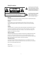
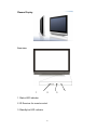
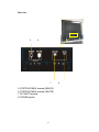
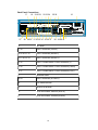
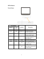
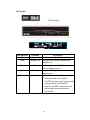
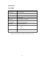
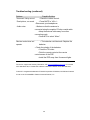
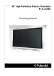
42” High-Definition Plasma Monitor
PLA-4255BD
Operation Manual
20041126
1
Table of Contents
Safety Precautions
3
Plasma Display
6
Set-Top Box
9
LED Indicators
12
Remote Control Unit
13
Installing the plasma Monitor
14
Basic Operation
15
Using the Remote Control
16
Basic Adjustments:
Video Source
17
PC Source
20
Audio Source
23
PIP Source
25
TV Source
26
Parental Menu
29
Settings Menu
32
Specifications
36
Troubleshooting
38
2
Safety Precautions
The lightning flask with arrowhead symbol,
within an equilateral triangle, is intended to
alert the user to the presence of uninsulated
“dangerous voltage” within the product’s
enclosure that may be of sufficient magnitude
to constitute a risk of electric to persons.
CAUTION: TO REDUCE THE RISK OF ELECTRIC SHOCK, DO NOT
REMOVE COVER (OR BACK). NO USE-SERVICEABLE PARTS INSIDE.
REFER SERVICING TO QUALIFIED SERVICE PERSONNEL.
The exclamation point within an equilateral
triangle is intended to alert the user to the
presence of important operating and
maintenance (servicing) instructions in the
literature accompanying the appliance.
Warning
The apparatus shall not be exposed to dripping or splashing and that no objects filled with liquids,
such as vases, shall be placed on the apparatus.
Caution
To prevent electric shock, match wide blade of plug to wide slot, fully insert. Refer to the
identification/rating label located on the back panel of your product for its proper operating
voltage.
Caution
Using video games or any external accessory with fixed images for extended periods of time can
cause them to be permanently imprinted on the picture tube (or projection TV picture tubes).
ALSO, some network/program logos, phone numbers, etc. may cause similar damage. This
damage is not covered by your warranty.
Cable TV Installer
This reminder is provided to call your attention to Article 820-40 of the National Electrical Code
(Section 54 of the Canadian Electrical Code, Part 1) which provides guidelines for proper
grounding and, in particular, specifies that the cable ground shall be connected to the grounding
system of the building as close to the point of cable entry as practical.
Customer Record
You will find the model number and chassis number of your TV on the back of your TV set.
Record these numbers in the spaces provided below. Refer to them whenever you call customer
service or your dealer regarding this product.
Model Number:_______________________
Chassis Number:______________________
3
Important Safety Instructions
1. Read these instructions.
2. Keep these instructions.
3. Heed all warnings.
4. Follow all instructions.
5. Do not use this apparatus near water.
6. Clean only with dry cloth.
7. Do not block any ventilation openings. Install in accordance with the
manufacturer's instructions.
8. Do not install near any heat sources such as radiators, heat registers, stoves,
or other apparatus (including amplifiers) that produce heat.
9. Do not defeat the safety purpose of the polarized or grounding-type plug. A
polarized plug has two blades with one wider than the other. A grounding type
plug has two blades and a third grounding prong. The wide blade or third prong
is provided for your safety. If the provided plug does not fit into your outlet,
consult an electrician for replacement of the obsolete outlet.
10. Protect the power cord from being walked on or pinched particularly at plugs,
convenience receptacles, and the point where they exit from the apparatus.
11. Only use attachments/accessories specified by the manufacturer.
12. Use only the cart, stand, tripod, bracket, or table specified by the
manufacturer, or sold with the apparatus. When a cart is used, use caution
when moving the cart/apparatus combination to avoid injury from tip-over.
13. Unplug this apparatus during lightning storms or when unused for long
periods of time.
14. Refer all servicing to qualified service personnel. Servicing is required when
the apparatus has been damaged in any way, such as power-supply cord or plug
is damaged, liquid has been spilled or objects have fallen into the apparatus, the
apparatus has been exposed to rain or moisture, does not operate normally, or
has been dropped.
15. Warning - This product should only be serviced by an authorized and
properly trained technician. Opening the cover or other attempts by the user to
service this product may result in serious injury or death from electrical shock,
and may increase the risk of fire.
4
FCC Statement of Compliance
Class B Computing Device Information to User
This equipment has been tested and found to comply with the limits for a Class B
Digital Device pursuant to part 15 of FCC Rules. These limits are designed to
provide reasonable protection against harmful interference in a residential
installation. This equipment generates, uses, and can radiate radio frequency
energy and, if not installed and used in accordance with the instructions, may
cause harmful interference to radio communications. However, there is no
guarantee that interference will not occur in a particular installation. If this
equipment receives interference while off and on, the user is encouraged to try
to correct the interference by one or more of the following measures:
1) Reorient or relocate the receiving antenna.
2) lncrease the separation between the equipment and TV.
3) Connect the equipment into an outlet on a circuit different from that to
which the TV is connected.
4) Consult the dealer or an experienced radio/TV technician for help and
for additional suggestions.
The user may find the following booklet prepared by the Federal
Communications Commission helpful: "How to Identify and Resolve Radio - TV
Interference Problems". This booklet is available from the US Government
Printing Office. Washington, D.C. 20402, Stock No. 004-000-00345-4.
FCC Warning
The user is cautioned that changes or modifications not expressly approved by
the manufacturer could void the user's authority to operate the equipment.
NOTE: In order for an installation of the product to maintain compliance with the
limits for a Class B Device, shielded cables must be used.
5
Plasma Display
Front view
1
2
1. Status LED indicator
2. IR Receiver for remote control
3. Standby/on LED indicator
6
3
Right view
1
2
3
4
1. STANDBY/ON button
2. VOLUME +/- buttons
3. CHANNEL +/- buttons
4. INPUT button
7
Rear view
5
6
7
5. SYSTEM CABLE terminal (BLACK)
6. SYSTEM CABLE terminal (WHITE)
7. AC INLET terminal
8. POWER switch
8
8
Set-Top Box
Front view
9
10
11
12
13
14 15
9. Push here to open the access panel door
10. COMPUTER (PC) INPUT terminal (ANALOG RGB)
11. COMPUTER (PC) INPUT terminal (AUDIO)
12. VIDEO 3 INPUT terminal (S-VIDEO)
13. VIDEO 3 INPUT terminal (VIDEO)
14. VIDEO 3 INPUT terminal (AUDIO L)
15. VIDEO 3 INPUT terminal (AUDIO R)
9
Back Panel Connections
17
18 19 20 21 22 23 24
27
28 29 30 31 32 33 34 35 36 37
25 26
16
38 39 40 41
16
AC INLET
17 30
INPUT terminals (VIDEO)
18 20 25 31 32
INPUT terminals (AUDIO L)
19 21 26 32 34
INPUT terminals (AUDIO R)
22 35
INPUT COMPONENT VIDEO terminals (Y)
23 36
INPUT COMPONENT VIDEO terminals (Cb/Pb)
24 37
INPUT COMPONENT VIDEO terminals (Cr/Pr)
27
Antenna Cable
28 29
INPUT terminals (S-VIDEO)
38
DVI cable terminal
39
SERVICE terminal
40
SYSTEM CABLE terminal (WHITE)
41
SYSTEM CABLE terminal (BLACK)
10
LED Indicators
Plasma Display
LED indicator
Condition
STATUS
Off
Off
Off
Flash
Off
Red
Description
AC power off The AC power is off
Standby to on Only lights when power
switches from standby to on.
Standby
The power LED lights up in red
to indicate standby mode
Off
Blue
On
Red
Blue
Sleep
Flash
Blue
DVI connector The DVI connector on the
error
system cable is disconnected
to Plasma Display.
Flash
Flash
DFP connector The DFP connector on the
error
System cable is disconnected
to Plasma Display.
11
The indicator on the Plasma
Display lights up blue to
indicate power-on.
Sleep mode is going to go off.
Set-Top Box
LED indicator
Condition
Description
Off
AC power off
The AC power of Set-Top Box is off
Flash
Standby to on
Only lights when power switches from
standby to on.
Blue
On
The indicator on the Set-Top Box lights up
blue to indicate power-on.
Red
Standby
The power LED lights up in red to indicate
standby mode
Flash
Error
1. The DVI connector on the system cable
is disconnected to Set-Top Box.
2. The DFP connector on the system cable
is disconnected to Set-Top Box.
3. Both DVI and DFP connectors on the
system cable are disconnected to
Set-Top Box.
12
Remote Control
Button labels
SETUP
Functions
Universal Function Key
Turns on the power to the Plasma Display or
PWR
places it into standby mode
TV/CBL/VCR/AUX
Device buttons
Digits 0 - 9
Access to main input #0~9 directly
MUTE
Mute main audio
ENTER/PIP SOURCE
Switch PIP source
VOL+/-
Increase/decrease main volume
LAST
Go to the last channel
INPUT
View the current input source and select
video input sources
GUIDE/WIDE
Select aspect ratio
FAV/EXIT
Indicate favorite channel
SELECT
Select an OSD option when the OSD is
active
Up/down/left/right arrows Navigate up/down/left/right in the OSD
INFO
Indicate input formation in use
MENU
View the on-screen-display (OSD)
VIDEO 1 - 3
Select composite/S-video inputs
VIDEO 4 - 5
Access to component video inputs
DVI
Select DVI input
MODE
Select picture mode
- FAV CH +
Delete channel from/ Add channel to
Favorite Channel List
PIP
Select PIP/PBP mode
FREEZE
Freeze the image
DTV
Used in digital TV
MTS
Select stereo: Auto, SAP and Mono
CC
Close caption toggling on/off
SLEEP
Sleep Timer
VGA
Select VGA input
TV
Select TV input
LED indicator
Lights red while a button is pressed
SWAP
Swap the main window and the PIP window
13
Installing the Plasma Display
Locating
•
•
Avoid direct sunlight. Maintain adequate ventilation.
The length of the system cable used to connect the Plasma Display and
the Set-Top Box is about 3 m (118 inches).
•
Because the Plasma Display is heavy, be sure to have someone to help
you when moving it.
•
Do not place anything on the top of the Media Receiver; it will not receive
enough ventilation and will not operate properly.
Note
Allow enough space around the upper and back parts when installing to ensure
ventilation around the backside of the Plasma Display.
Preparation
Connecting the cable between the PDP and the Set-Top Box:
•
White connectors connect to the WHITE terminal on the Set-Top Box and
DVI terminal on the PDP.
•
Black connectors connect to the BLACK terminal on the Set-Top Box and
DFP terminal on the PDP.
14
Basic Operation
Turning on the power
Check that the AC switches on the back of the PDP and the Set-Top Box are
turned to “I”.
1. Press PWR on the Plasma Display and Set-Top Box. The power LED on PDP
and Set-Top Box light up in red to indicate standby mode.
2. Confirm that the STANDBY indicators light up red, and then press TV on the
remote control unit or STANDYBY/ON on the right side of Plasma Display to turn
the system on. The POWER ON indicators on the Plasma Display and Set-Top
Box light up blue.
Note
In this manual, “system” means the Plasma Display Panel and the Media
Receiver (Set-Top Box).
Turning off the power
Press PWR button on the remote control or STANDBY/ON button on the right
side of the PDP. The power LEDs on the PDP and the Set-Top Box turn red to
indicate standby mode.
CAUTION
Before disconnecting any system cables, turn the PDP off (put into Standby
Mode) and turn the AC switches to “0”.
Note
If the PDP is not to be used for a long period of time, unplug the AC cord from the
wall outlet.
15
Basic Operation
Using the Remote Control
Use the remote control unit by pointing it towards the remote sensor window.
Objects between the remote control unit and sensor window may prevent proper
operation.
Inserting batteries
Install batteries in the remote control unit before using:
1. Open the battery cover.
2. Insert the two AA size batteries supplied with the product. Place batteries
with their terminals corresponding to the (+) and (-) indicators in the
battery compartment.
3. Close the battery cover.
Cautions regarding the remote control unit:
•
Do not expose the remote control unit to shock. In addition, do not expose
the remote control unit to liquids, and do not place in an area with high
humidity.
•
Do not leave the remote control unit under direct sunlight. The heat may
cause deformation of the unit.
•
The remote control unit may not work properly if the remote sensor
window of the Plasma Display is under direct sunlight or strong lighting. In
such case, change the angle of the lighting or Plasma Display set, or
operate the remote control unit closer to the remote sensor window.
•
If the remote control unit fails to operate Plasma Display System
functions, replace the batteries in the remote control unit.
16
Basic Adjustments for VIDEO Source
Use the menu to change the options.
1.
Press MENU.
2. Press ←/→ to select “VIDEO” source.
3. Press ↑/↓ to select the desired option, and then press SELECT.
4. Press MENU to exit the menu.
VIDEO
● PICTURE MODE
BRIGHTNESS
CONTRAST
SATURATION
HUE
SHARPNESS
PICTURE MODE
Adjust picture to your preference for the chosen Video option.
1.
Press MENU.
2.
3.
Press ←/→ to select “VIDEO” source.
Press ↑/↓ to select “PICTURE MODE”, and then press SELECT.
4.
Press ↑/↓ to select the desired option, and then press SELECT.
5.
Press MENU to exit.
17
Basic Adjustments for VIDEO Source (continued)
PICTURE MODE
● MOVIE
STANDARD
VIVID
SPORTS
For Picture mode
Item
MOVIE
STANDARD
VIVID
SPORTS
Description
For a movie.
For a highly defined image in a bright room.
For a clear, active image.
For a sports image.
VIDEO
PICUTURE MODE
● BRIGHTNESS
CONTRAST
SATURATION
HUE
SHARPNESS
1. Press MENU.
2. Press ←/→ to select “VIDEO” source.
3. Press ↑/↓ to select an item to be adjusted, and then press SELECT.
4. Press ←/→ to select the desired level, and then press SELECT.
When an adjustment screen is displayed, you can also change an item to be
adjusted, by press ↑/↓.
5
Press MENU to exit the menu.
18
Basic Adjustments for VIDEO Source (continued)
For Video source
Item
←button
→button
BRIGHTNESS
CONTRAST
SATURATION
HUE
For less brightness
For less contrast
For less saturation
For less color intensity
For more brightness
For more contrast
For more saturation
For more color intensity
SHARPNESS
For less sharpness
19
For more sharpness
Basic Adjustments for PC Source
PC
● AUTO
COLOR TEMP
CLOCK
PHASE
POSITION
AUTO
Auto image adjustment.
1. Press MENU.
2. Press ←/→ to select “PC” source.
3. Press ↑/↓ to select “AUTO”, and then press SELECT.
4. Press ←/→ to select the desired parameter—“YES” or “NO”, and then press
SELECT.
5. Press MENU to exit the menu.
COLOR TEMPERATURE
Adjust the color temperature to give a better white balance.
1. Press MENU.
2. Press ←/→to select “PC” source.
3. Press ↑/↓ to select “COLOR TEMP”, and then press SELECT.
4. Press ↑/↓ to select the desired option, and then press SELECT.
5. Press MENU to exit the menu.
20
Basic Adjustments for PC Source (continued)
Color Temp
● Warm
Normal
Cool
Item
Warm
Normal
Cool
Description
for warm tone
for natural tone
for cool tone
CLOCK
Clock adjustment
1. Press MENU.
2. Press ←/→ to select “PC” source, and then press SELECT..
3. Press ↑/↓ to select “CLOCK”, and then press SELECT.
4. Press ←/→ to select the desired level, and then press SELECT.
5. Press MENU to exit the menu.
PHASE
Phase adjustment.
1. Press MENU.
2. Press ←/→ to select “PC” source.
3. Press ↑/↓ to select “PHASE”, and then press SELECT.
4. Press ←/→ to select the desired level, and then press SELECT.
5. Press MENU to exit the menu.
21
Basic Adjustments for PC Source (continued)
POSITION
Adjusts the vertical and horizontal positions of displayed images.
1. Press MENU.
2. Press ←/→ to select “PC” source.
3. Press ↑/↓ to select “POSITION”, and then press SELECT.
4. Press ↑/↓ to select “X” or “Y”, and then press SELECT.
5. Press ←/→ to select the desired level, and then press SELECT.
6. Press MENU to exit the menu.
22
Basic Adjustments for AUDIO Source
For AUDIO source
AUDIO
● BASS
TREBLE
BALANCE
SRS TS XT
BASS
Adjusts the bass weaker or stronger.
1. Press MENU.
2. Press ←/→ to select “AUDIO” source.
3. Press ↑/↓ to select “BASS”, and then press SELECT.
4. Press ←/→ to select the desired level, and then press SELECT.
5. Press MENU to exit the menu.
TREBLE
Adjusts the treble weaker or stronger.
1. Press MENU.
2. Press ←/→ to select “AUDIO” source.
3. Press ↑/↓ to select “TREBLE”, and then press SELECT.
4. Press ←/→ to select the desired level, and then press SELECT.
5. Press MENU to exit the menu.
BALANCE
Adjusts audio output between left and right speakers.
1. Press MENU.
2. Press ←/→to select “AUDIO” source.
3. Press ↑/↓ to select “BALANCE”, and then press SELECT.
4. Press ←/→ to select the desired level, and then press SELECT.
Basic Adjustments for AUDIO Source (continued)
SRS TS XT
Reproduces highly effective three-dimensional sound.
1. Press MENU.
23
2. Press ←/→ to select “AUDIO” source.
3. Press ↑/↓ to select “SRS TS XT”, and then press SELECT.
4. Press ↑/↓ to select the desired parameter (OFF or ON):
Item
Description
OFF
Deactivates SRS TruSurround XT sound effect
ON
Activates SRS TruSurround XT sound effect
TruSurround XT, SRS and
symbol are trademarks
of SRS Labs, Inc.
TruSurround XT technology is incorporated under license
from SRS Labs, Inc.
24
Basic Adjustments for PIP Source
PIP
● PIP POSITION
PIP SIZE
PIP POSITION
Adjusts the PIP position.
1. Press MENU.
2. Press ←/→ to select “PIP” source.
3. Press ↑/↓ to select “PIP POSITION”, and then press ENTER.
4. Press ←/→ to select “X” or “Y”.
5. Press ↑/↓ to select the desired level.
PIP SIZE
Adjusts the PIP size.
1. Press MENU.
2. Press ←/→ to select “PIP” source, and then press SELECT.
3. Press ↑/↓ to select “PIP SIZE”, and then press SELECT.
4. Press ←/→ to select the desired option (OFF/SMALL/MEDIUM/PBP)
PIP OPTIONS
I/O terminal placement on
the cabinet
25
Basic Adjustments for TV Source
TV
● SYSTEM
CHANNEL EDIT
SYSTEM
This section describes how to search and set up conventional TV channels that
you can watch under the current conditions. Unless you set up conventional TV
channels using SYSTEM, you may not be able to tune in those channels.
1. Press MENU.
2. Press ←/→ to select “TV” source.
3. Press ↑/↓ to select “SYSTEM”, and then press .SELECT.
4. Press ↑/↓ to select the desired option, and then press SELECT.
For System source
Item
Antenna
Stand-cable
HRC-cable
Description
For Antenna
For Standard Cable
For HRC Cable
IRC-cable
For IRC Cable
26
Basic Adjustments for TV Source (continued)
CHANNEL EDIT
CHANNEL EDIT
● AUTO PROGRAM
ADD
DELETE
AUTO PROGRAM
Auto channel preset automatically searches and sets up conventional TV
channels.
This section describes how to search and set up conventional TV
channels that you can watch under the current conditions. Unless you set
up conventional TV channels using AUTO PROGRAM, you may not be
able to tune in those channels.
1. Press MENU.
2. Press ←/→ to select “TV” source.
3. Press ↑/↓ to select “CHANNEL EDIT”, and then press SELECT.
4. Press ↑/↓ to select the “AUTO PROGRAM”, and then press SELECT.
ADD
Setting for adding channels.
From among conventional TV channels searched and set up using AUTO
PROGRAM, you can select channels to be added when CH+/- are operated.
5. Press MENU.
6. Press ←/→ to select “TV” source.
7. Press ↑/↓ to select “CHANNEL EDIT”, and then press SELECT.
8. Press ↑/↓ to select the “ADD”, and then press SELECT.
27
Basic Adjustments for TV Source (continued)
DELETE
Setting for skipping unwanted channels.
From among conventional TV channels searched and set up using AUTO
PROGRAM, you can select channels to skipped when CH+/- are operated.
1. Press MENU.
2. Press ←/→ to select “TV “source.
3. Press ↑/↓ to select “CHANNEL EDIT”, and then press SELECT.
4. Press ↑/↓ to select the “DELETE”, and then press SELECT.
PARENTAL
Prevents your children from watching specified types of TV programs.
This tool gives parents a great degree of control over broadcasts accessed by
their children. It allows parents to select programs judged suitable for child
viewing while blocking ones judged not suitable.
This tool functions for both conventional and digital TV channels.
˙The U.S. has two rating systems for viewing content: TV Parental Guidelines
and movie ratings.
˙The TV Parental guidelines work in conjunction with the V-CHIP to help parents
screen out inappropriate television shows from their children.
˙Movie ratings are used for original movies rated by the Motion Picture
Association of America (MPAA) as watched on cable TV and not edited for
television. The V-CHIP can also be set to block MPAA-rated movies.
28
Basic Adjustments for Parental Menu
PARENTAL
● LOCK MENU
NEW PASSWORD
MPAA RATING
TV PG RATING
LOCK MENU
The parental menu will be locked by pressing “LOCK MENU”
1. Press MENU.
2. Press ←/→ to select “PARTENTAL” source.
3. Press ↑/↓ to select “LOCK MENU”, and then press SELECT,
the message “ENTER THE VCHIP PASSWORD:” will be displayed.
4. Enter the password on the remote (factory default: 0000), then the menu will
be locked.
NEW PASSWORD
To change the password.
1. Press MENU.
2. Press ←/→ to select “PARTENTAL” source.
3. Press ↑/↓ to select “NEW PASSWORD”, and then press SELECT,
the message “ENTER NEW VCHIP PASSWORD:” will be displayed.
4. Enter the number you want (4 digits).
5. Press ↑/↓ to return to LOCK MENU option and then press SELECT, the
parental menu will be locked with new password.
29
MPAA RATING
Voluntary movie rating system (MPAA)
Rating
NA
G
PG
Description
None available
General audiences. All ages admitted.
Parental guidance suggested. Some material may not
be suitable for children.
PG-13
Parents strongly cautioned. Some material may be
inappropriate for children under 13.
R
Restricted. Under 17 requires accompanying parent or
adult guardian (age varies in some jurisdictions).
NC-17
No one 17 and under admitted.
X
A rating that has now been superseded by NC-17.
1. Press MENU.
2. Press ←/→ to select “PARENTAL” source.
3. Press ↑/↓ to select “MPAA RATING”, and then press SELECT.
4. Press ↑/↓ to select the desired option, and then press SELECT.
30
Basic Adjustments for Parental Menu (continued)
TV RG RATING
TV PARENTAL GUIDELINES
Content
Rating
Violence
Sexual
Content
Foul
Suggestive
F
Language Dialog
Violence
TV-Y
(All children)
AgeBase
TV-Y7
(Directed to older
children)
X
TV-G
(General audience)
TV-PG
(Parental guidance
suggested)
TV-14
(Parents strongly
X
X
X
X
X
X
X
X
X
X
X
cautioned)
TV-MA
(Mature audience only)
X: Content rating can be set.
1. Press MENU.
2. Press ←/→ to select “PARENTAL” source.
3. Press ↑/↓ to select “TV RG RATING”, and then press SELECT.
4. Press ↑/↓ to select the desired option, and then press SELECT.
31
Basic Adjustments for Settings Menu
For SETTING source
OSD LANGUAGE
You can select a language to be used for the on-screen display of menus from
three languages; English, French and Spanish.
1. Press MENU.
2. Press ←/→ to select “SETTING” source”.
3. Press ↑/↓ to select “OSD LANGUAGE”, and then press SELECT.
4. Press ↑/↓ to select the desired language (English, French, Spanish)
5. Press SELECT.
6. Press MENU to exit the menu.
FIRMWARE VER
Displays the version of firmware.
1. Press MENU.
2. Press ←/→ to select “SETTING” source”.
3. Press ↑/↓ to select “FIRWARE VER”, and then press SELECT.
RESTORE DEFAULT
To restore the factory default settings.
1. Press MENU.
2. Press ←/→ to select “SETTING” source”.
3. Press ↑/↓ to select “RESTORE DEFAULT”, and then press SELECT.
4. Press ←/→ to select the desired option “YES” or “NO” and then press
SELECT.
32
Basic Adjustments for Settings Menu (continued)
TRANSPARENCY
To adjust the transparency degree of OSD.
1. Press MENU.
2. Press ←/→ to select “SETTING” source”.
3. Press ↑/↓ to select “TRANSPARENCY”, and then press SELECT.
4. Press ←/→ to select the desired level and then press SELECT.
5. Press MENU to exit the menu.
CC CONTROL
CC means “Closed Caption”. Your Plasma Display System is equipped with an
internal closed caption decoder. Closed caption is a system which allows you to
view conversations, narration, and sound effects in TV programs and home
videos as subtitles on your Plasma Display screen.
˙Not all programs and videos offer closed caption.
Please look for the “CC” symbol to ensure that captions will be shown.
1. Press MENU.
2. Press ←/→ to select “SETTING” source”.
3. Press ↑/↓ to select “CC CONTROL”, and then press SELECT to activate or
deactivate CC CONTROL.
4. Press MENU to exit the menu.
33
Basic Adjustments for Settings Menu (continued)
MODE
Selecting the type of closed captions.
˙”CC-1” or “CC-2” or “CC-3” or “CC-4” displays subtitles of TV dramas and news
programs while allowing a full view of the picture.
˙”TEXT-1” or “TEXT-2” or “TEXT-3” or “TEXT-4” superimposes on the picture
other information(e.g. TV guide, weather) that is independent of the TV in
progress.
1. Press MENU.
2. Press ←/→ to select “SETTING” source”.
3. Press ↑/↓ to select “MODE”, and then press SELECT.
4. Press ↑/↓ to select desired option
(CC1/CC2/CC3/CC4/TEXT1/TEXT2/TEXT3/TEXT4).
5. Press SELECT.
6. Press MENU to exit the menu.
34
Basic Adjustments for Settings Menu (continued)
DISPLAY
To adjust the showing way of subtitles.
1. Press MENU.
2. Press ←/→ to select “SETTING” source.
3. Press ↑/↓ to select “DISPLAY”, and then press SELECT.
4. Press ↑/↓ to select desired option (BOX or SHADOW).
5. Press SELECT.
6. Press MENU to exit the menu.
35
Specifications
PLA-4255BD
Item
42” Plasma Display Panel
Native Resolution
1024(H) x 768(V) pixels
Effective Display Size
933.89 mm (H) x 532.24 mm (V)
Aspect Ratio
16:9
Color
16.77million colors
Viewing Angle
> 160° (horizontal) / > 160° (vertical)
Brightness
1000 cd/m2 ( typical, panel spec)
(w/glass filter)
Contrast Ratio
Dimensions
Weight
Min.350 cd/m, 400 cd/m (Typical)
3000:1 (Typical, panel spec)
Height
820mm
Width
1095mm
Depth
91mm
Net
49.8kgs ±0.5kgs
Design and specifications are subject to change without notice.
36
Specifications
PLA-4255BDSTB
Item
Set-Top Box (Media Receiver)
Video System
NTSC
Input Signal Interface
Front:
1 x Composite Video (1x RCA) + 1x S-Video (1x 4-Pin DIN) + 1x
Stereo Audio (2x RCA, Left + Right)
1x Analog RGB (1x 15-Pin D-Sub) + 1x Stereo Audio (1x Stereo
Mini Jack)
Rear:
1x RF Connector for internal NTSC Tuner
2 x [1x Composite Video (1x RCA) + 1x S-Video (1x 4-Pin DIN) +
1x Stereo Audio (2x RCA, Left + Right)]
2x [1x Component (3x RCA, YPbPr/YCbCr) + 1x Stereo Audio
(2x RCA, Left + Right)]
1x Digital Video (1x DVI) + 1x Stereo Audio (2x RCA, Left + Right)
HDCP support
Output Signal Interface
1x Subwoofer (w/o amp)
1x Headphone (mini-Jack stereo)
1x DVI (for PDP connection)
1 x DFP (for PDP connection)
Power Input
100 to 240 Vac
Power Consumption
30W (Max.)
Dimension
Height
107.4mm
Width
420.7mm
Depth
224mm
Net
3.5kgs±0.5kgs
Weight
Design and specifications are subject to change without notice.
“DCDi by Faroudja” is a registered trademark of Genesis Microchip, Inc.
All rights reserved.
37
Troubleshooting
Problem
Possible Solution
˙No picture.
Can not see video at VIDEO 1,2,3 • Select source again.
Cannot receive any channels.
• Make sure the power cord is connected
securely.
• Turn on the power of the PDP.
• Check antenna/cable connections.
______________________________________________________________
˙TV is locked to one channel.
• Perform Auto Program to add receivable
channels that are not presently in the PDP’s
memory.
Cannot receive any channels
• Run Auto Program to add receivable
when using cable TV.
channels that are not presently in the PDP’s
memory.
Cannot receive or select
• Run Auto Program to add receivable
channels.
channels that are not presently in the PDP’s
memory.
Can not see any information
on display (OSD and video)
and the power LED is blue.
˙Poor picture
Double images or ghosts.
˙Turn off AC power of Box and PDP,
and turn on again.
• Check antenna/cable connections.
• Check the antenna location and direction.
˙Only snow and noise appear
• Check if the antenna is broken or bent.
on the screen.
• Check if the antenna has reached the end of
its serviceable life.
______________________________________________________________
˙No color.
• Press MODE to select the desired Picture
Mode.
˙Color is not correct.
• Adjust the Picture Mode options in the
Dark picture
Video menu.
_____________________________________________________________
38
Troubleshooting (continued)
Problem
˙No sound./ Noisy sound.
˙Good picture, no sound.
Audio noise.
Possible Solution
• Check the volume control.
• Press MUTE or VOL +/-.
• Disconnect your headphones.
• Make sure that the antenna is
connected using the supplied 75-ohm coaxial cable.
• Keep the antenna cable away from other
connecting cords.
• Press MTS to select “Mono”.
_____________________________________________________________
Remote control does not
• The batteries could be weak. Replace the
operate.
batteries.
• Check the polarity of the batteries.
• Press the TV button.
• Point the remote control at the remote
control sensor of the PDP.
• Install the PDP away from fluorescent lights.
For service, support and warranty information, visit www.polaroidelectronics.com or in the US
call 1-866-289-5168, in Canada call 1-866-301-7922 and in Mexico call 01-800-400-2443.
“Polaroid” is a registered trademark of Polaroid Corporation of Waltham, MA USA and licensed
for use on the PLA-4255BD to Petters Consumer Brands, LLC.
39