1
INSTALLATION, OPERATION AND MAINTENANCE MANUAL
POLARIS - SERIES TBM 200 LH ( 8” ) - TYPE PHO / PBO / PVO
DOCUMENT NBR. :
REVISION:
PED-010
1
1of 29
EFFECTIVE
DATE:
08-24-2004
POLARIS SERIES TBM 200 LH ( 8" ) TYPE PHO / PBO / PVO
ELECTRO-SUBMERSIBLE PUMP
PUMP TYPE:
TBM 200 LH ( 8" ) TYPE (
POLARIS PART NBR.:
700.200.05.
HP / V / Hz / Poles:
/
/
INSULATION:
F
H
EXPLOSION PROOF:
Y
N
/
SUPER H
EQUIPMENT OPTIONS:
POWER CABLE:
VITON MOTOR O-RINGS
VITON SEAL ELASTOMERS
“SEAL GUARD”
“SLURRY BOSS”
“MOTOR SENTRY”
SS MOTOR FLANGE
COAL TAR EPOXY
PUMP SERIAL NUMBER:
DATE:
CUSTOMER:
CUSTOMER P.O. NBR.
SHIPPED TO:
ADDITIONAL
)
(FEET)
INSTALLATION, OPERATION AND MAINTENANCE MANUAL
POLARIS - SERIES TBM 200 LH ( 8” ) - TYPE PHO / PBO / PVO
DOCUMENT NBR. :
REVISION:
PED-010
1
2of 29
EFFECTIVE
DATE:
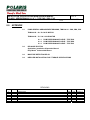
TABLE OF CONTENTS
SECTION 1.0
INTRODUCTION
SECTION 2.0
WARRANTIES
SECTION 3.0
SAFETY
SECTION 4.0
MECHANICAL INSTALLATION
4.1
RECEIVING INSPECTION
4.2
STORAGE
4.2.1
4.2.2
4.2.3
4.3
HANDLING
4.4
MECHANICAL SEAL INSPECTION
4.5
PUMP SET UP / MOUNTING
4.5.1
4.5.2
4.5.3
4.6
CABLE AND CHAIN SUSPENSION
OPTIONAL LIFTING / SUSPENSION BAIL MOUNTING
FLOOR MOUNTING
PIPING
4.6.1
4.6.2
4.6.3
4.6.4
SECTION 5.0
NEW PUMP AND EQUIPMENT STORAGE
USED PUMP STORAGE
SPARE PARTS STORAGE
DISCHARGE PIPING / DISCHARGE HOSE
PRIMARY SEAL FLUSH PIPING
OPTIONAL WATER JACKET / PIPING
OPTIONAL WATER JET RING
ELECTRICAL INSTALLATION
5.1
5.2
5.3
GENERAL
MOISTURE DETECTION RELAY - THERMAL PROTECTION
INSTALLATION
REFER TO THE RELIANCE ELECTRIC MOTOR
INSTALLATION & MAINTENANCE MANUAL FOR
DUTY MASTER SUBMERSIBLE MOTORS (SECTION 8.2)
08-24-2004
INSTALLATION, OPERATION AND MAINTENANCE MANUAL
POLARIS - SERIES TBM 200 LH ( 8” ) - TYPE PHO / PBO / PVO
DOCUMENT NBR. :
REVISION:
PED-010
1
SECTION 6.0
08-24-2004
PRE START UP CHECK
PUMP START UP
PUMP SHUT DOWN
TROUBLE SHOOTING
WET END INSTALLATION
7.1
7.2
7.3
SECTION 8.0
EFFECTIVE
DATE:
OPERATION
6.1
6.2
6.3
6.4
SECTION 7.0
3of 29
TBM 200 LH - Type PHO - Open Suction, Strainer
TBM 200 LH - Type PBO - Open Suction, Strainer, Solids Mixer Attachment
TBM 200 LH - Type PVO - Open Suction, Strainer, Shredder Attachment
APPENDIX
8.1
PUMP GENERAL ARRANGEMENT DRAWING, TBM 200 LH – PHO / PBO / PVO
8.1.1
8.1.2
8.1.3
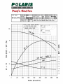
PUMP PERFORMANCE CURVE TYPE - PHO
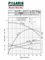
PUMP PERFORMANCE CURVE TYPE - PBO
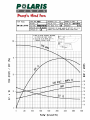
PUMP PERFORMANCE CURVE TYPE - PVO
8.2
RELIANCE ELECTRIC MOTOR
INSTALLATION & MAINTENANCE MANUAL FOR
DUTY MASTER SUBMERSIBLE MOTORS
8.3
MOISTURE DETECTION RELAY
8.4
IMPELLER INSTALLATION / BOLT TORQUE REQUIREMENTS
INSTALLATION, OPERATION AND MAINTENANCE MANUAL
POLARIS - SERIES TBM 200 LH ( 8” ) - TYPE PHO / PBO / PVO
DOCUMENT NBR. :
REVISION:
PED-010
1
1.0
4of 29
EFFECTIVE
DATE:
08-24-2004
INTRODUCTION
Your new Series TBM pump has been designed and manufactured to perform for many years
with a minimum of maintenance. However, parts will wear and need replacing eventually. The
period between maintenance will greatly depend on the service and your maintenance program.
Series TBM pumps are heavy-duty Electro-submersible pumps featuring motor armatures with a
nominal service factor up to 2 depending on pump wet end and motor combination.
Pumps with standard motors are designed to operate completely submersed in liquids with pH
values from 6–14 and temperatures not exceeding 40°C (104°F). Higher temperatures and / or
dry-running applications will require H or Super H insulation and / or an optional water jacket.
Motor modules of series TBM can be ordered in standard configuration
or as explosion proof units per
Class 1, Groups C&D, Temperature code T3C
UL Listed, File No. E10822
CSA Certified, File No. LR19467-15 (Frames 140,180,210,250 & 360)
CSA Certified, File No. LR19467-15 (Frame 320)
This manual has been compiled to help you minimize your maintenance and speed repairs when
required. Read and understand this manual.
Please provide the Serial Number of your equipment if additional manuals are needed.
WHEN ORDERING PARTS ALWAYS REFER TO PUMP SERIAL NUMBER.
THIS NUMBER IS FOUND ON THE NAMEPLATE ON THE PUMP.
INSTALLATION, OPERATION AND MAINTENANCE MANUAL
POLARIS - SERIES TBM 200 LH ( 8” ) - TYPE PHO / PBO / PVO
DOCUMENT NBR. :
REVISION:
PED-010
1
2.0
5of 29
EFFECTIVE
DATE:
08-24-2004
WARRANTIES
Seller warrants that the products covered by this contract conform to applicable drawings and
specifications accepted in writing by Seller, will be free from defects in material and workmanship,
will be merchantable and will perform in accordance with the detailed specifications accepted in
writing by Seller.
These warranties extend for a period of twelve (12) months from the date of purchase by Buyer.
Buyer’s exclusive remedy and Seller’s sole duty under these warranties is to repair or replace the
product. Normal wear and tear on Seller’s product shall not constitute a warranty defect.
THERE ARE NO OTHER WARRANTIES, EXPRESS OR IMPLIED, WHICH EXTEND BEYOND THOSE SET
FORTH ABOVE. THE WARRANTY OF MERCHANTABILITY IS LIMITED TO THE PERIOD SPECIFIED ABOVE.
These warranties are contingent upon the product being stored, installed, maintained, and
operated in accordance with good engineering practices and the instructions contained in the
Operating and Maintenance Manual. Failure to do so shall operate to void all warranties.
Seller’s total responsibility for damages whether arising in contract or tort arising out of or relating
to the performance of the product or the warranties hereunder shall be strictly limited to the
contract price for the product. In no event shall Seller be liable for any incidental or consequential
damages such as lost profits, loss of use of productive facilities or equipment, expenses or
damages incurred in reliance on the product's performance or lost production whether suffered by
buyer or any third party.
Seller warrants that the products comply with OSHA standards on drive guard design and
construction (if applicable) in effect at the time of manufacture and makes no other warranty with
respect to any other standards. Seller shall not be responsible for failure of parts to fit properly
due to deterioration of or modification to Buyer’s existing equipment for which such parts are
furnished.
Seller makes no warranty or guarantee that the product supplied hereunder will comply with the
performance of Buyer’s existing equipment.
Seller reserves the right to furnish substitutes for material not available or whose use is restricted.
The use of (a) non-OEM components or (b) non-OEM pump spare parts and/or (c) non-approved
modifications to the product and/or (d) failure to install a moisture detection relay and/or (e) failure
to connect the thermal overload protection wiring will operate to void all warranties.
We reserve the right to change the design, construction or material of any part without incurring
the obligation of installing such changes on pumps already delivered.
INSTALLATION, OPERATION AND MAINTENANCE MANUAL
POLARIS - SERIES TBM 200 LH ( 8” ) - TYPE PHO / PBO / PVO
DOCUMENT NBR. :
REVISION:
PED-010
1
3.0
6of 29
EFFECTIVE
DATE:
08-24-2004
SAFETY
Do not install the equipment other than in accordance with the instructions contained in this
manual.
When required information cannot be found in this manual, contact the nearest POLARIS PUMPS
representative.
This instruction book should be read completely before starting installation, maintenance or
operation. The equipment is capable of trouble free operation when properly installed, operated
and maintained. These instructions present the basic information and methods required for
proper installation and maintenance.
This pump has been designed to provide safe and reliable service, however as with all equipment
of this type, the operator(s) must exercise good judgment and proper safety practices to avoid
damage to the equipment and surroundings and to avoid personal injury. The instructions in this
manual are intended for personnel with a general training in operation and maintenance of
centrifugal pumps and electric motors.
It is assumed that your safety department has established a safety program based upon a
thorough analysis of industrial hazards. Before installing, operating or performing maintenance on
the pump and associated components described in this manual, it is suggested that the safety
program be reviewed to ensure that it covers the hazards arising from rotating- and electrical
machinery. In general, all personnel should be guided by all the basic rules of safety associated
with the equipment and the process.
It should be understood that the information contained in this manual does not relieve operating
and maintenance personnel of the responsibility of exercising normal good judgment in operation
and care of the pump and its components.
INSTALLATION, OPERATION AND MAINTENANCE MANUAL
POLARIS - SERIES TBM 200 LH ( 8” ) - TYPE PHO / PBO / PVO
DOCUMENT NBR. :
REVISION:
PED-010
1
4.0
7of 29
EFFECTIVE
DATE:
08-24-2004
INSTALLATION
4.1 RECEIVING INSPECTION
The unit must be inspected immediately upon arrival and any irregularities and damages
due to shipment must be reported to the carrier and POLARIS PUMPS. A copy of this
manual is included in the shipment. Put this manual a safe, accessible place for ready
reference when required. It is important that the entire contents of this manual are studied
before installation.
Pump parts and accessories may be packed inside shipping container, or attached to skids
in individual packages. Inspect all containers, crates and skids before discarding.
4.2
STORAGE
4.2.1 NEW PUMP AND EQUIPMENT STORAGE
If your new pump is to be stored for a long period before use, the following
procedures must be adhered to in order for POLARIS PUMPS to extend the normal
warranties.
Notify POLARIS PUMPS that the equipment is to be stored and that the storage
procedures will be followed. Notify POLARIS PUMPS when the equipment is to be
removed from storage and put into service.
Failure to notify POLARIS PUMPS will result in your warranty being void. Your new
pump will arrive ready for use. Close off all flush and cooling water inlet ports and
cooling water exhaust ports on water jackets. Suitable covers out of plywood or
plastic must be installed on the suction entrance and discharge to provide adequate
protection against dirt, dust and nesting animals. The main power and control cable
ends must be protected by means of suitable shrink-on boots or similar to prevent
the ingress of moisture during storage.
Equipment should be stored in a dry location and situated on an even surface with
no strains applied. If stored outdoors, the equipment must be covered with a
waterproof tarp secured to the equipment or skid.
INSTALLATION, OPERATION AND MAINTENANCE MANUAL
POLARIS - SERIES TBM 200 LH ( 8” ) - TYPE PHO / PBO / PVO
DOCUMENT NBR. :
REVISION:
PED-010
1
8of 29
EFFECTIVE
DATE:
08-24-2004
4.2.2 USED PUMP STORAGE
A used pump should be completely disassembled and all parts cleaned and
inspected. All unpainted metal surfaces should be coated with grease or suitable
protectant. All previously painted parts should be touched up or repainted.
Reassemble the pump as per Sections 7.0 and store as per Section 4.2.1.
4.2.3 SPARE PARTS STORAGE
Spare parts may not arrive at your site with adequate protection for long-term
storage unless it was specified in your parts order. It is the customer's responsibility
to ensure that all spare parts are prepared and packaged for long term storage.
Components such as mechanical seal assemblies and parts should be left in their
original sealed containers. The long-term storage of elastomer (rubber) parts must
be given consideration since elastomers may have a short shelf live under certain
circumstances.
4.3
HANDLING
Use care when moving pumps. Sling pumps so that any protruding components will not be
damaged. Do not use choke type sling or chain arrangements for skids or containers.
Make sure that the lifting equipment is rated to safely handle the weight of the pump and
auxiliary equipment.
See relevant general arrangement drawings (Section 8.0) or bills of materials for weight
information.
4.4
MECHANICAL SEAL INSPECTION
The pump was checked during assembly and testing for proper alignment of the pump
components. Rough handling during shipment, storage or preparation for installation could
cause damage to mechanical seals. POLARIS PUMPS are equipped with tandem
mechanical seals and should be checked for any oil leakage on the wet end side. This is to
ensure that the seal faces did not receive any damage during shipment, storage or
preparation for installation.
INSTALLATION, OPERATION AND MAINTENANCE MANUAL
POLARIS - SERIES TBM 200 LH ( 8” ) - TYPE PHO / PBO / PVO
DOCUMENT NBR. :
REVISION:
PED-010
1
4.5
9of 29
EFFECTIVE
DATE:
08-24-2004
PUMP SET UP / MOUNTING
4.5.1 CABLE AND CHAIN SUSPESION
Pumps of SERIES TBM are fitted with integral lifting lugs sized to accommodate the
dead weight of the pump assembly. Verify the weight of your specific pump before
making lifting cable or chain selection.
See relevant general arrangement drawings (Section 8.0) or bills of materials for
weight information.
4.5.2 OPTIONAL LIFTING / SUSPENSION BAIL MOUNTING
Optional lifting bails are available for all pumps of SERIES TBM for applications
where a single lifting cable or chain is preferred.
4.5.3 FLOOR MOUNTING
When Pumps are operated resting on the pump stand on the sump floor, they must
rest on a horizontal surface that prevents the pump from tipping over and burying
itself. A chain or cable with limited slack can be utilized to prevent this.
4.6
PIPING
4.6.1 DISCHARGE HOSE / DISCHARGE PIPING
Flexible, heavy duty, non-collapsible discharge hose is preferred.
All rigid piping must be independently supported. Pump casing should never bear
the weight of the piping. Non-collapsible, expansion type joints are recommended on
the discharge side of the pump for rigid pipe installations.
INSTALLATION, OPERATION AND MAINTENANCE MANUAL
POLARIS - SERIES TBM 200 LH ( 8” ) - TYPE PHO / PBO / PVO
DOCUMENT NBR. :
REVISION:
PED-010
1
10of 29
EFFECTIVE
DATE:
08-24-2004
4.6.2 PRIMARY SEAL FLUSH
The seal flush / cooling water to the outboard mechanical seal is automatically
supplied if the pump is running. Be aware that if the pump is operated in applications
where the sump can be pumped dry, a minimum water level must be present to
prevent the mechanical seal from dry running. If the sump level falls below the
minimum requirement, the higher than normal seal temperatures can cause the seal
faces to crack due to thermal shock once the sump water level rises back and
quenches the hot seal faces.
Refer to the general arrangement drawing of your pump (Section 8.0) for the
minimum sump level requirement and install suitable level controls.
4.6.3 OPTIONAL WATER JACKET / PIPING
An optional water jacket must be installed if the pump is operated in applications
where the sump can be pumped dry below the minimum water level and the pump
remains running for periods exceeding 15 minutes. This is to prevent
overheating and subsequent burnout of the stator windings.
Cooling water should be 3 GPM at 60 P.S.I. maximum pressure at a
temperature not exceeding 40◦C (104◦F).
Water must be clean so that no sand, etc., is pumped into the water jacket.
INSTALLATION, OPERATION AND MAINTENANCE MANUAL
POLARIS - SERIES TBM 200 LH ( 8” ) - TYPE PHO / PBO / PVO
DOCUMENT NBR. :
REVISION:
PED-010
1
5.0
11of 29
EFFECTIVE
DATE:
08-24-2004
ELECTRICAL INSTALLATION
5.1
GENERAL
Power supply and electrical work must be as per local and national codes. All wiring
and installation of cables, relays, disconnects, etc., should be performed by qualified
personnel. Check that main line voltage and frequency agree with the specifications
on the motor data plate. Prior to installation of any wiring, inspect both main power
and control cable for possible cuts and tears.
5.2
MOISTURE SENSOR RELAY
Failure to install / operate the specified Motor Moisture-Detection Relay and
not connecting the thermal over-load wiring will void your Warranty.
POLARIS PUMPS requires the use of a Warrick Controls - Type 2810 moisture
detection relay. This relay must be purchased with your pump as an integral part of
the package to validate your warranty.
See Section 8.3 for dimensional information and wiring diagram.
5.3
INSTALLATION
All activities related to the electrical installation, maintenance and operation and
service of the motor module must be in accordance with the
RELIANCE ELECTRIC
Application, Installation & Operation Manual
Duty Master Submersible Motors
See Section 8.2 of this pump manual.
INSTALLATION, OPERATION AND MAINTENANCE MANUAL
POLARIS - SERIES TBM 200 LH ( 8” ) - TYPE PHO / PBO / PVO
DOCUMENT NBR. :
REVISION:
PED-010
1
6.0
12of 29
EFFECTIVE
DATE:
08-24-2004
OPERATION
6.1
PRE-START UP CHECK
A pre-start up check should always be performed prior to putting your pump into
service. The following procedures should be adhered to as a minimum.
• POWER SUPPLY
Double-check and confirm that the power supply voltage and frequency match
with the pump data plate.
• WIRING
Double-check all power and control cable connections. Check and confirm that
all ground leads are connected and properly grounded.
• CONTROL SYSTEM
Double-check that all control equipment is powered up and operational.
• CABLES
Inspect both power and control cables for visual damage such as cuts and tears
in the jacket.
• OIL LEVEL
Double-check the motor seal oil level
• ROTATION CHECK
Correct rotation is counter clock wise as viewed from the pump intake side. In
case of wrong rotation, switch two of the three main power leads. Do not run the
pump in air longer than required to verify proper rotation.
• COOLING AND FLUSH WATER
Double-check all connections, hoses and piping and ensure that the water supply
is turned on for applications requiring motor cooling. Visually confirm that the
cooling water is circulating and exiting through the exhaust opening of the water
jacket prior to start up.
INSTALLATION, OPERATION AND MAINTENANCE MANUAL
POLARIS - SERIES TBM 200 LH ( 8” ) - TYPE PHO / PBO / PVO
DOCUMENT NBR. :
REVISION:
PED-010
1
6.2
13of 29
EFFECTIVE
DATE:
08-24-2004
PUMP START UP
Whenever possible, start the pump in clear liquid to prime discharge piping and/or
hoses. If flexible hoses are used, make sure that they are not pinched since the
pressure developed by the pump may not be enough to force them open.
Lower the pump slowly into the material to be pumped.
Mixture density can be monitored via a current meter. Higher current draw of the
pump will indicate higher density and therefore higher production rate. The mixture
density can be controlled by raising or lowering the pump into the material.
Be aware of the mixture characteristics for your specific application. It is important
that you maintain a pipeline velocity above the critical settling velocity of the solids
mixture being pumped to prevent the solids from settling out and clogging the
discharge line.
Never stop the pump while pumping solids through the system. This will plug the
piping. Before shut down, raise the pump into clean water and completely flush the
discharge line.
During the initial few days of operation while all parts are still new, observe the
discharge gauge readings as well as the motor amperage draw. If a flow meter is
available, monitor the pump output as well.
These readings should be taken and recorded periodically and will help you to
establish an inspection and maintenance schedule. Keeping track of your pumps
performance will make it easier to identify problems before they become serious and
cause undue damage.
INSTALLATION, OPERATION AND MAINTENANCE MANUAL
POLARIS - SERIES TBM 200 LH ( 8” ) - TYPE PHO / PBO / PVO
DOCUMENT NBR. :
REVISION:
PED-010
1
6.3
14of 29
EFFECTIVE
DATE:
08-24-2004
PUMP SHUT DOWN
Never stop the pump while pumping solids through the system. This will plug the
piping. Lift the pump into clear fluid for as long as it takes to flush the entire system
of any slurry.
IMPORTANT
If you operate and store your pump in environments subject to below-freezing
temperatures:
1.
After the pump has been shut down, completely drain wet end, water jacket
and piping. Failure to do so will result in serious damage to your equipment.
2.
Be aware that the motor seal oil can thicken during cold storage to the point
where it will be too viscous and can not provide adequate lubrication for startup. Pre-heat the pump as required before start up.
3.
Be aware that certain elastomer components (lip seals, o-rings etc.) must not
be operated if their temperature is below -4°F (-20°C). Pre-heat the pump as
required before start up.
INSTALLATION, OPERATION AND MAINTENANCE MANUAL
POLARIS - SERIES TBM 200 LH ( 8” ) - TYPE PHO / PBO / PVO
DOCUMENT NBR. :
REVISION:
PED-010
1
6.4
15of 29
EFFECTIVE
DATE:
08-24-2004
TROUBLE SHOOTING
6.4.1 FAULT TRACING
To carry out fault tracing on electrical equipment, a multi-meter, test lamp and wiring
diagram are required. Fault tracing must be done with the power disconnected
unless checks cannot be performed without power to the motor. If a fault is detected,
be sure to keep all personnel clear of the pump when the power is turned on. A
qualified electrician must perform all electrical work. Obey all local codes and
regulations and follow recommended safety procedures.
The following Checklist is designed to aid in identifying possible faults, assuming the
pump has been in operation and functioned previously.
All activities related to the electrical installation, maintenance and operation and
service of the motor module must be in accordance with the
RELIANCE ELECTRIC
Application, Installation & Operation Manual
Duty Master Submersible Motors
See Section 8.2 of this pump manual.
-
FAULT SIGNAL AT THE STARTER
If the stator temperature is too high, check that the pump motor is completely
submerged or that the water supply to the water jacket is turned on during operation
and that the impeller rotates freely.
In case of a moisture sensor fault, check the condition of the oil and check for water
in the motor housing and oil sump. Make sure the overload protection is reset.
INSTALLATION, OPERATION AND MAINTENANCE MANUAL
POLARIS - SERIES TBM 200 LH ( 8” ) - TYPE PHO / PBO / PVO
DOCUMENT NBR. :
REVISION:
PED-010
1
-
16of 29
EFFECTIVE
DATE:
08-24-2004
FAULT SIGNAL AT THE STARTER, PUMP CAN BE STARTED MANUALLY
Check for faulty level-control system components (start or high water sensors).
Clean or replace as required.
Check for faulty control equipment. Check that all connections are intact. Check
relay and actuator windings. Test actuator switch for contact in both manual and
automatic mode.
-
PUMP CAN NOT BE STARTED MANUALLY, NO VOLTAGE TO PUMP
Check that the main power switch is on. Check for control voltage to the starter
equipment and that all fuses are intact.
Check that all supply line phases are live and that all fuses are intact and properly
fitted. Check that the overload protection relay is reset. Check for breaks in the
motor cable.
-
PUMP CAN NOT BE STARTED MANUALLY, VOLTAGE IS GOING TO PUMP
If this is the case, some oversized material or other debris may have jammed the
impeller, solids mixer or shredder.
CAUTION: Disconnect and lock out the main power supply before working in the
intake area of the pump. Failure to do so can result in serious injury.
Clean out and remove any objects that may have jammed the impeller and inspect
the pump components for any visual damage. Inspect the sump area and remove
any oversized material and debris. Inspect pump strainer for excessive wear and
replace if required.
-
PUMP CAN BE STARTED, MOTOR PROTECTION TRIPS
Check that the overload protection is not set too low or is defective. Check the
breaker set point vs. the amperage on the motor data plate and adjust or replace
overload protection relay as required.
Check for free rotation of the impeller. If it is not easily rotated, or feels tight, check
for tramp material within the pump. Using an Amp-meter, check the current on all
three phases. Using a Meg-ohm meter, check the insulation between the phases
and ground. If the phase amp readings are too high or uneven, or a ground fault is
detected, contact POLARIS PUMPS.
INSTALLATION, OPERATION AND MAINTENANCE MANUAL
POLARIS - SERIES TBM 200 LH ( 8” ) - TYPE PHO / PBO / PVO
DOCUMENT NBR. :
REVISION:
PED-010
1
-
17of 29
EFFECTIVE
DATE:
08-24-2004
PUMP IS EXPECTED TO STOP BUT KEEPS RUNNING
If the pump has been running satisfactory and is capable of emptying the
sump to the control stop level, check for leakage in discharge piping and
connections. Leakage water may be re-circulated back into the sump.
Check that the impeller or suction is not clogged.
CAUTION: Disconnect and lock out the main power supply before working in
the intake area of the pump. Failure to do so can result in serious injury.
Clean out and remove any objects that may have clogged the impeller and
inspect the pump components for any visual damage. Inspect the sump area
and remove any oversized material and debris. Inspect pump strainer for
excessive wear and replace if required.
Check that the impeller and casing are not worn and need to be replaced.
Check the impeller running clearance and adjust as required.
Check for faults in the level control equipment. Clean and inspect the level
sensor probes and perform a function test. Check the level control relay
contactor and holding circuit. Replace any faulty components. Check the
location of the stop level probe to ensure it is not set too low.
-
PUMP STARTS AND STOPS REPEATEDLY
Check if the back flow from the discharge pipe is enough to raise the sump
level to the level-controller starting probe. If so, positioning a rubber flap valve
in the discharge pipe close enough to the pump will minimize back-flow.
Check that the distance between start and stop level probes is not too short.
Check that the contactor does not break its self-holding function. Check the
voltage in the control circuit in relation to the rated voltage on the coil. Check
the functioning of the stop sensor probe. The voltage drop in the line during
the start-up surge can cause the contactor self-holding function to break.
INSTALLATION, OPERATION AND MAINTENANCE MANUAL
POLARIS - SERIES TBM 200 LH ( 8” ) - TYPE PHO / PBO / PVO
DOCUMENT NBR. :
REVISION:
PED-010
1
-
18of 29
EFFECTIVE
DATE:
08-24-2004
PUMP IS RUNNING WITH REDUCED FLOW
This can be caused by either pump and / or system related problems.
Check your system set-up:
Verify that all piping connections are tight and that there are no leaks in the
discharge line.
Check that any valves are fully open and operable and the discharge line and
valves are not clogged.
Check your system-head requirement. The pump flow will reduce if the point
of discharge has been raised or additional piping has been added.
Check your pump:
Verify proper direction of rotation.
Check the pump intake area to ensure that the impeller, strainer and mixer or
shredder is not clogged.
Visually inspect the wet-end components for wear. The performance of the
pump can be significantly reduced if casing and impeller have experienced
excessive wear. Check the impeller running clearance and adjust if required.
Replace parts as required.
INSTALLATION, OPERATION AND MAINTENANCE MANUAL
POLARIS - SERIES TBM 200 LH ( 8” ) - TYPE PHO / PBO / PVO
DOCUMENT NBR. :
REVISION:
PED-010
1
7.0
19of 29
EFFECTIVE
DATE:
08-24-2004
WET END INSTALLATION
Inspect and inventory all parts before you begin assembly. Clean all parts and
remove protective coatings as required. Inspect the motor module for any visual
damage paying particular attention to the shaft end and mechanical seal. Remove
any protective coatings from the shaft end and check to make sure that the tapped
hole in the end of the shaft and the key seat are free of any shavings and dirt. Prior
to the physical assembly of the wet end, familiarize yourself with all of the
components and the assembly sequence by reading the assembly instructions and
the enclosed explosion drawings. Based on your particular pump model and size
gather the necessary tools as per the following tool list.
TOOL REQUIREMENTS
Series TBM - 200 LH - Type “PHO”
-
Allen wrenches 5/8” - 14 mm - 6 mm
Plastic or Rubber Hammer
“Never-Seize” or “Molykote”, “Locktite”
Series TBM - 200 LH - Types “PBO” and “PVO”
-
Allen wrenches 5/8” - 14 mm – 8 mm - 5 mm
Open ended wrench
2” or 51 mm
Plastic or Rubber Hammer
“Never-Seize” or “Molykote”, “Locktite”
INSTALLATION, OPERATION AND MAINTENANCE MANUAL
POLARIS - SERIES TBM 200 LH ( 8” ) - TYPE PHO / PBO / PVO
DOCUMENT NBR. :
REVISION:
PED-010
1
7.1
TBM 200 LH - TYPE PHO
20of 29
EFFECTIVE
DATE:
08-24-2004
Drawing A0207 and A0210
Apply "Never-Seize" to the motor shaft end. Position Flinger Gasket (Item
060.2) onto shaft. Insert Drive Key (Item 113) into the key seat. Slide Flinger
(Item 110) onto the shaft. Position Impeller Gasket (Item 060.1) against the
Impeller flinger.
Hoist the Volute Casing (Item 102) into position and insert into the motor
flange spigot. Apply “Never-Seize” to the Socket Head Cap Screws and insert
with Lock Washers (Items 040.1, 040.4) through the motor flange into the
Casing and tighten.
Slide the Impeller (Item 101) onto the shaft. Position the O-ring (Item 062.2)
onto the Impeller Cap (Item 107) and the same into the impeller bore, lining
up the groove in the cap face with the key. Position O-Ring (Item 062.1) onto
the Impeller Lock Screw (Item 040.3), apply “Locktite” and insert into the shaft
end and tighten.
Refer to Appendix - 8.4 for Impeller Lock Screw Torque and Procedure
Position Casing Gaskets (Item 060.3) onto Strainer (Item 103), aligning the
holes. To verify the impeller running clearance, compare the depth from the
top of the strainer to the gaskets with the depth from the casing face to the
impeller vanes. The total difference should be 1/32” – 1/16”. Adjust as
necessary by adding or subtracting casing gaskets.
Slide strainer and gaskets into the casing bore. Position the Pump Stand
(Item 112) over the strainer, insert “Never-Seize” coated Socket Head Cap
Screws and Lock Washers (Items 040.2, 040.4) and tighten.
Apply “Never-Seize” to the Countersunk Head Cap Screws (Item 040.5),
insert the Intake Screen (Item 111) and screws into the strainer and tighten.
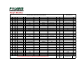
POLARIS PUMPS - SERIES TBM - 200 LH TYPE PHO
ITEM
ITEM
ITEM
151
PART NUMBER
QTY.
DESCRIPTION
EXT. DESC.1
A0210 (Rev.0) 1/2
MODEL1
MODEL 2
WT.(lbs)
375.57
826.37
MTL.
DWG. #
C0182
151.200.05.00240
1
KIT, WET END - BASIC
101
101.012.05.00213
1
IMPELLER
RH, 5V
TBM 200LH
PHO, PBO, PVO
A532 CL III TP. A
102
102.012.05.00215
1
CASING
VOLUTE
TBM 200LH
PHO, PBO, PVO
A532 CL III TP. A
D0184
103
103.012.05.00217
1
LINER
SUCTION
TBM 200LH
PHO, PBO, PVO
A532 CL III TP. A
D0186
110
110.082.05.00228
1
FLINGER
TBM 200LH
FRAME 320TY/360TYS
ASTM A564 Gr.630 (17-4 PH)
B0193
112
112.056.05.00231
1
STAND
PUMP
TBM 200LH
PHO, PBO, PVO
ASTM A36
C0197
113
113.052.05.00235
1
KEY
DRIVE
FRAME 320TY/360TYS
PHO, PBO, PVO
SAE 1045
B0111
041.1
041.200.05.00260
1
KIT, FASTENER
040.1
040.084.00.00254
8
FASTENER
SCREW
HEX SOCKT.HD.CAP
DIN 912 / M16 X 55
A4/70
040.2
040.084.00.00255
8
FASTENER
SCREW
HEX SOCKT.HD.CAP
DIN 912 / M16 X 70
A4/70
040.3
040.084.00.00257
1
FASTENER
SCREW
HEX SOCKT.HD.CAP
ANSI B18.3 / 3/4"UNC X 2.50"
A4/70
040.4
040.084.00.00070
16
FASTENER
WASHER
LOCK
DIN 127B / M16
061.200.05.00252
1
KIT, GASKET
060.1
060.101.05.00232
1
GASKET
IMPELLER
FRAME 320 TY / 360 TYS
PHO, PBO, PVO
GYLON-3500, .031"
B0044
060.2
060.101.05.00233
1
GASKET
FLINGER
FRAME 320 TY / 360 TYS
PHO, PBO, PVO
GYLON-3500, .031"
B0044
061.200.05.00253
1
KIT, GASKET
060.3
060.102.05.00234
4
GASKET
CASING
TBM200LH
PHO, PBO, PVO
"BLUE GARD", .125"
B0045
TBM 200LH
PHO
TBM 200LH
PHO
QT400
B0195
061.1
061.2
152
152.200.05.00241
1
KIT, INTAKE SCREEN
111
111.053.05.00229
1
SCREEN
041.2
041.200.05.00261
1
KIT, FASTENER
040.084.00.00258
3
FASTENER
040.5
153
TBM 200LH
WT.(KG)
A4/70
GYLON-3500
BLUE-GARD
INTAKE
3.57
7.85
A4/70
SCREW
HEX SOCKT, CSK.HD.FLAT
DIN 7991 / M12 X 30
TBM 200LH
PHO
TBM 200LH
PHO
A4/70
153.200.05.00242
1
KIT, IMPELLER CAP
107
107.082.05.00225
1
CAP
063.1
063.200.05.00246
1
KIT, O-RING
062.1
062.131.00.00249
1
O-RING
18 x 2
72 NBR
062.2
062.131.00.00248
1
O-RING
80 x 3
72 NBR
IMPELLER
1.75
3.85
ASTM A564 Gr.630 (17-4 PH)
B0191
72 NBR
SEE TABLE BELOW FOR COMPLETE PUMP PART NUMBERS AND MOTOR DETAILS
380.89
838.07
ESTIMATED WEIGHT
TOTAL
INSTALLATION, OPERATION AND MAINTENANCE MANUAL
POLARIS - SERIES TBM 200 LH ( 8” ) - TYPE PHO / PBO / PVO
DOCUMENT NBR. :
REVISION:
PED-010
1
7.2
TBM 200 LH - TYPE PBO
23of 29
EFFECTIVE
DATE:
08-24-2004
Drawing A0208 and A0211
Apply "Never-Seize" to the motor shaft end. Position Flinger Gasket (Item
060.2) onto shaft. Insert Drive Key (Item 113) into the key seat. Slide Flinger
(Item 110) onto the shaft. Position Impeller Gasket (Item 060.1) against the
Impeller flinger.
Hoist the Volute Casing (Item 102) into position and insert into the motor
flange spigot. Apply “Never-Seize” to the Socket Head Cap Screws and insert
with Lock Washers (Items 040.1, 040.4) through the motor flange into the
Casing and tighten.
Slide the Impeller (Item 101) onto the shaft. Position the O-rings (Item 062.2,
062.3) onto the Shaft Adapter (Item 108) and the same into the impeller bore,
lining up the groove in the cap face with the key. Position O-Ring (Item 062.1)
onto the Impeller Lock Screw (Item 040.3), apply “Locktite” and insert into the
shaft end and tighten.
Refer to Appendix - 8.4 for Impeller Lock Screw Torque and Procedure
Apply “Never-Seize” to the adapter thread and screw on the Shaft Extension
(Item 109). Tighten the shaft extension via the wrench flats on the outboard
end. Position the O-ring (Item 062.4) into the shaft extension thread relief.
Position Casing Gaskets (Item 060.3) onto Strainer (Item 103), aligning the
holes. To verify the impeller running clearance, compare the depth from the
top of the strainer to the gaskets with the depth from the casing face to the
impeller vanes. The total difference should be 1/32” – 1/16”. Adjust as
necessary by adding or subtracting casing gaskets.
Slide strainer and gaskets into the casing bore. Position the Pump Stand
(Item 112) over the strainer, insert “Never-Seize” coated Socket Head Cap
Screws and Lock Washers (Items 040.2, 040.4) and tighten.
Apply “Never-Seize” to the Countersunk Head Cap Screws (Item 040.5),
insert the Intake Screen (Item 111) and screws into the strainer and tighten.
Apply “Never-Seize” to the shaft extension thread and screw on the Solids
Mixer (Item 106). Tighten using a plastic or rubber hammer.
POLARIS PUMPS - SERIES TBM - 200 LH TYPE PBO
ITEM
ITEM
ITEM
151
PART NUMBER
QTY.
DESCRIPTION
EXT. DESC.1
A0211 (Rev.0) 1/2
MODEL1
MODEL 2
WT.(lbs)
375.57
826.37
MTL.
DWG. #
C0182
151.200.05.00240
1
KIT, WET END - BASIC
101
101.012.05.00213
1
IMPELLER
RH, 5V
TBM 200LH
PHO, PBO, PVO
A532 CL III TP. A
102
102.012.05.00215
1
CASING
VOLUTE
TBM 200LH
PHO, PBO, PVO
A532 CL III TP. A
D0184
103
103.012.05.00217
1
LINER
SUCTION
TBM 200LH
PHO, PBO, PVO
A532 CL III TP. A
D0186
110
110.082.05.00228
1
FLINGER
TBM 200LH
FRAME 320TY/360TYS
ASTM A564 Gr.630 (17-4 PH)
B0193
112
112.056.05.00231
1
STAND
PUMP
TBM 200LH
PHO, PBO, PVO
ASTM A36
C0197
113
113.052.05.00235
1
KEY
DRIVE
FRAME 320TY/360TYS
PHO, PBO, PVO
SAE 1045
B0111
041.1
041.200.05.00260
1
KIT, FASTENER
040.1
040.084.00.00254
8
FASTENER
SCREW
HEX SOCKT.HD.CAP
DIN 912 / M16 X 55
A4/70
040.2
040.084.00.00255
8
FASTENER
SCREW
HEX SOCKT.HD.CAP
DIN 912 / M16 X 70
A4/70
040.3
040.084.00.00257
1
FASTENER
SCREW
HEX SOCKT.HD.CAP
ANSI B18.3 / 3/4"UNC X 2.50"
A4/70
040.4
040.084.00.00070
16
FASTENER
WASHER
LOCK
DIN 127B / M16
061.200.05.00252
1
KIT, GASKET
060.1
060.101.05.00232
1
GASKET
IMPELLER
FRAME 320 TY / 360 TYS
PHO, PBO, PVO
GYLON-3500, .031"
B0044
060.2
060.101.05.00233
1
GASKET
FLINGER
FRAME 320 TY / 360 TYS
PHO, PBO, PVO
GYLON-3500, .031"
B0044
061.200.05.00253
1
KIT, GASKET
060.3
060.102.05.00234
4
GASKET
CASING
TBM200LH
PHO, PBO, PVO
"BLUE GARD", .125"
B0045
061.1
061.2
154
TBM 200LH
WT.(KG)
A4/70
GYLON-3500
BLUE-GARD
154.200.05.00243
1
KIT, MIXER
TBM 200LH
PBO
106
106.012.05.00223
1
MIXER
ROTATING
TBM 200LH
PBO
A532 CL III TP. A
C0188
111
111.053.05.00230
1
SCREEN
INTAKE
TBM 200LH
PBO
QT400
B0196
041.2
041.200.05.00261
1
KIT, FASTENER
040.084.00.00258
3
FASTENER
040.5
156
6.37
14.05
A4/70
SCREW
HEX SOCKT, CSK.HD.FLAT
DIN 7991 / M12 X 30
A4/70
156.200.05.00245
1
KIT, SHAFT EXTENSION
TBM 200LH
PBO, PVO
108
108.082.05.00226
1
ADAPTER
SHAFT
TBM 200LH
PBO, PVO
1.75
3.85
ASTM A564 Gr.630 (17-4 PH)
B0192
109
109.082.05.00227
1
EXTENSION
SHAFT
TBM 200LH
PBO, PVO
ASTM A564 Gr.630 (17-4 PH)
B0190
063.200.05.00246
1
KIT, O-RING
062.1
062.131.00.00249
1
O-RING
18 x 2
72 NBR
062.2
062.131.00.00248
1
O-RING
80 x 3
72 NBR
063.200.05.00247
1
KIT, O-RING
062.3
062.131.00.00250
1
O-RING
50 x 3
72 NBR
062.4
062.131.00.00251
1
O-RING
20 x 6
72 NBR
063.1
063.2
72 NBR
72 NBR
SEE TABLE BELOW FOR COMPLETE PUMP PART NUMBERS AND MOTOR DETAILS
383.69
844.27
ESTIMATED WEIGHT
TOTAL
INSTALLATION, OPERATION AND MAINTENANCE MANUAL
POLARIS - SERIES TBM 200 LH ( 8” ) - TYPE PHO / PBO / PVO
DOCUMENT NBR. :
REVISION:
PED-010
1
7.3
TBM 200 LH - TYPE PVO
26of 29
EFFECTIVE
DATE:
08-24-2004
Drawing A0209 and A0212
Apply "Never-Seize" to the motor shaft end. Position Flinger Gasket (Item
060.2) onto shaft. Insert Drive Key (Item 113) into the key seat. Slide Flinger
(Item 110) onto the shaft. Position Impeller Gasket (Item 060.1) against the
Impeller flinger.
Hoist the Volute Casing (Item 102) into position and insert into the motor
flange spigot. Apply “Never-Seize” to the Socket Head Cap Screws and insert
with Lock Washers (Items 040.1, 040.4) through the motor flange into the
Casing and tighten.
Slide the Impeller (Item 101) onto the shaft. Position the O-rings (Item 062.2,
062.3) onto the Shaft Adapter (Item 108) and the same into the impeller bore,
lining up the groove in the cap face with the key. Position O-Ring (Item 062.1)
onto the Impeller Lock Screw (Item 040.3), apply “Locktite” and insert into the
shaft end and tighten.
Refer to Appendix - 8.4 for Impeller Lock Screw Torque and Procedure
Apply “Never-Seize” to the adapter thread and screw on the Shaft Extension
(Item 109). Tighten the shaft extension via the wrench flats on the outboard
end. Position the O-ring (Item 062.4) into the shaft extension thread relief.
Position Casing Gaskets (Item 060.3) onto Strainer (Item 103), aligning the
holes. To verify the impeller running clearance, compare the depth from the
top of the strainer to the gaskets with the depth from the casing face to the
impeller vanes. The total difference should be 1/32” – 1/16”. Adjust as
necessary by adding or subtracting casing gaskets.
Slide strainer and gaskets into the casing bore. Position the Pump Stand
(Item 112) over the strainer, insert “Never-Seize” coated Socket Head Cap
Screws and Lock Washers (Items 040.2, 040.4) and tighten.
Apply “Never-Seize” to the Socket Head Cap Screws (Item 040.6) insert the
Stationary Shredder (Item 105) and screws into the strainer. Insert SetScrews (Item 040.7) into stationary shredder. Apply “Never-Seize” to the shaft
extension thread and screw on the Rotating Shredder (Item 104). Tighten
using a plastic or rubber hammer. Adjust shredder clearance to 0.5 mm
(0.020”) using the set-screws and tighten the socket head cap screws.
POLARIS PUMPS - SERIES TBM - 200 LH TYPE PVO
ITEM
ITEM
ITEM
151
PART NUMBER
QTY.
DESCRIPTION
EXT. DESC.1
A0211 (Rev.0) 1/2
MODEL1
MODEL 2
WT.(lbs)
375.57
826.37
MTL.
DWG. #
C0182
151.200.05.00240
1
KIT, WET END - BASIC
101
101.012.05.00213
1
IMPELLER
RH, 5V
TBM 200LH
PHO, PBO, PVO
A532 CL III TP. A
102
102.012.05.00215
1
CASING
VOLUTE
TBM 200LH
PHO, PBO, PVO
A532 CL III TP. A
D0184
103
103.012.05.00217
1
LINER
SUCTION
TBM 200LH
PHO, PBO, PVO
A532 CL III TP. A
D0186
110
110.082.05.00228
1
FLINGER
TBM 200LH
FRAME 320TY/360TYS
ASTM A564 Gr.630 (17-4 PH)
B0193
112
112.056.05.00231
1
STAND
PUMP
TBM 200LH
PHO, PBO, PVO
ASTM A36
C0197
113
113.052.05.00235
1
KEY
DRIVE
FRAME 320TY/360TYS
PHO, PBO, PVO
SAE 1045
B0111
041.1
041.200.05.00260
1
KIT, FASTENER
040.1
040.084.00.00254
8
FASTENER
SCREW
HEX SOCKT.HD.CAP
DIN 912 / M16 X 55
A4/70
040.2
040.084.00.00255
8
FASTENER
SCREW
HEX SOCKT.HD.CAP
DIN 912 / M16 X 70
A4/70
040.3
040.084.00.00257
1
FASTENER
SCREW
HEX SOCKT.HD.CAP
ANSI B18.3 / 3/4"UNC X 2.50"
A4/70
040.4
040.084.00.00070
16
FASTENER
WASHER
LOCK
DIN 127B / M16
061.200.05.00252
1
KIT, GASKET
060.1
060.101.05.00232
1
GASKET
IMPELLER
FRAME 320 TY / 360 TYS
PHO, PBO, PVO
GYLON-3500, .031"
B0044
060.2
060.101.05.00233
1
GASKET
FLINGER
FRAME 320 TY / 360 TYS
PHO, PBO, PVO
GYLON-3500, .031"
B0044
061.200.05.00253
1
KIT, GASKET
060.3
060.102.05.00234
4
GASKET
CASING
TBM200LH
PHO, PBO, PVO
"BLUE GARD", .125"
061.1
061.2
155
TBM 200LH
WT.(KG)
A4/70
GYLON-3500
BLUE-GARD
7.50
B0045
155.200.05.00244
1
KIT, SHREDDER
TBM 200LH
PVO
104
104.012.05.00219
1
SHREDDER
ROTATING
TBM 200LH
PVO
16.50
A532 CL III TP. A
C0200
105
105.012.05.00221
1
SHREDDER
STATIONARY
TBM 200LH
PVO
A532 CL III TP. A
C0202
041.200.05.00262
1
KIT, FASTENER
040.6
040.084.00.00256
3
FASTENER
SCREW
HEX SOCKT.HD.CAP
DIN 912 / M12 X 35
A4/70
040.7
040.084.00.00259
3
FASTENER
SCREW
HEX SOCKT.SET
DIN 913 / M12 X 20
A4/70
041.2
156
A4/70
156.200.05.00245
1
KIT, SHAFT EXTENSION
TBM 200LH
PBO, PVO
108
108.082.05.00226
1
ADAPTER
SHAFT
TBM 200LH
PBO, PVO
7.80
17.16
ASTM A564 Gr.630 (17-4 PH)
B0192
109
109.082.05.00227
1
EXTENSION
SHAFT
TBM 200LH
PBO, PVO
ASTM A564 Gr.630 (17-4 PH)
B0190
063.200.05.00246
1
KIT, O-RING
062.1
062.131.00.00249
1
O-RING
18 x 2
72 NBR
062.2
062.131.00.00248
1
O-RING
80 x 3
72 NBR
063.200.05.00247
1
KIT, O-RING
062.3
062.131.00.00250
1
O-RING
50 x 3
72 NBR
062.4
062.131.00.00251
1
O-RING
20 x 6
72 NBR
063.1
063.2
72 NBR
72 NBR
SEE TABLE BELOW FOR COMPLETE PUMP PART NUMBERS AND MOTOR DETAILS
390.87
860.03
ESTIMATED WEIGHT
TOTAL
INSTALLATION, OPERATION AND MAINTENANCE MANUAL
POLARIS - SERIES TBM 200 LH ( 8” ) - TYPE PHO / PBO / PVO
DOCUMENT NBR. :
REVISION:
PED-010
1
8.0
29of 29
EFFECTIVE
DATE:
08-24-2004
APPENDIX
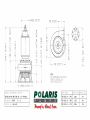
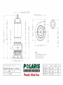
8.1
PUMP GENERAL ARRANGEMENT DRAWING, TBM 200 LH – PHO, PBO, PVO
TBM 200 LH – 40 / 50 / 60 HP MOTOR
TBM 200 LH – 75 / 100 / 125 HP MOTOR
8.1.1
8.1.2
8.1.3
PUMP PERFORMANCE CURVE - TYPE PHO
PUMP PERFORMANCE CURVE - TYPE PBO
PUMP PERFORMANCE CURVE - TYPE PVO
8.2
RELIANCE ELECTRIC
Application, Installation & Operation Manual
Duty Master Submersible Motors
8.2
MOISTURE DETECTION RELAY
8.4
IMPELLER INSTALLATION / BOLT TORQUE SPECIFICATIONS
REVISIONS
REV
0
1
ECN
CHANGE DESCRIPTION
NEW RELEASE
ADDED BOLT TORQUE SPECIFICATIONS
BY
APP
DATE
UJB
UJB
UJB
UJB
8 AUG, 01
24 AUG, 04
''#"*"&% %)*##*"&%
% '(*"&% #"%.
%$ # "% # %
&#-'!) +*- )*(. /
+$()"# +$' &*&()
")* &( #)) (&+') % "% *( &( , !&(* "$ +*-
$"%+*) "% "(
“Solutions
You Can
Trust”
%)*(+*"&%%+#/
/
'("#
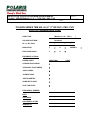
RECEIVING AND HANDLING . . . . . . . . . . . . . . . . . . . . . . . . . . . . . . . . . . . . . . . . . . . . . . . . . . . . . . . . . . . . . . . . . . . .
1
INSTALLATION . . . . . . . . . . . . . . . . . . . . . . . . . . . . . . . . . . . . . . . . . . . . . . . . . . . . . . . . . . . . . . . . . . . . . . . . . . . . . . . . 2, 3
MAINTENANCE . . . . . . . . . . . . . . . . . . . . . . . . . . . . . . . . . . . . . . . . . . . . . . . . . . . . . . . . . . . . . . . . . . . . . . . . . . . . . . . . 4, 5
THERMAL PROTECTION SYSTEM . . . . . . . . . . . . . . . . . . . . . . . . . . . . . . . . . . . . . . . . . . . . . . . . . . . . . . . . . . . . . . . 5, 6
MOISTURE DETECTION SYSTEM . . . . . . . . . . . . . . . . . . . . . . . . . . . . . . . . . . . . . . . . . . . . . . . . . . . . . . . . . . . . . . . . 6, 7
LEAD COLOR CODING . . . . . . . . . . . . . . . . . . . . . . . . . . . . . . . . . . . . . . . . . . . . . . . . . . . . . . . . . . . . . . . . . . . . . . . . .
8
STANDARD REPLACEMENT SEAL CROSS REFERENCE . . . . . . . . . . . . . . . . . . . . . . . . . . . . . . . . . . . . . . . . . . .
9
STANDARD REPLACEMENT O" RING CROSS REFERENCE . . . . . . . . . . . . . . . . . . . . . . . . . . . . . . . . . . . . . . . .
9
STANDARD REPLACEMENT SNAP RING CROSS REFERENCE . . . . . . . . . . . . . . . . . . . . . . . . . . . . . . . . . . . . . .
10
* ) #&%(*$* ** *) $)*(+* %$) )*+ / * &()%$$" $)*"" $ $ %&(* $
* ) '+ &#$* *%(%+"/ %( )*(* $ & *) $)*(+* %$) %( +*+(
(($
#%*%() )& $ * ) $)*(+* %$ %%! ( " )* %( &&" * %$ $ ")) (%+&) $ .&"%) %$1&(%% $, (%$#$*) "" (& () %*( *$ " (%$$*) $
%+*( )" (&"#$* )"" &(%(# / $ +*%( 0 " $ )(, " */ $/
%*( (& () &(%(# / * +)*%#( %( $%$1" $ )(, " * ) $*) * " )* $ $ #%*%( -(($*/
©Copyright Reliance Electric Industrial Company, 1996.
Revisions to this manual require Hazardous Approval Engineering and/or UL approval.
®Reliance and DutyMaster are registered trademarks of Reliance Electric Industrial Company
0
RECEIVING AND HANDLING
ACCEPTANCE
#*-*0"#'4 $).+ / /#$.
,0$+( )/ !* +/$)" .#$+( )/ !-*( /# /-).+*-//$*)
*(+)4 ! )4 *! /# "**. '' !*- $) /#
$'' *! '$)" *- 3+- .. - $+/ - (" */# ,0)/$/4 $. .#*-/ * )*/ +/ /# ( 0)/$' /#
!- $"#/ *- 3+- .. " )/ (& . ) ++-*+-$/
)*//$*) *) 4*0- !- $"#/ $'' *- 3+- .. - $+/
! )4 *) ' '*.. *- (" $. $.*1 - '/ - )*/$!4 4*0- !- $"#/ *- 3+- .. " )/ / *)
) - ,0 ./ #$( /* (& ) $).+ /$*) 2$''
..$./ 4*0 $) *'' /$)" '$(. !*- '*.. *- ("
$) .#$+( )/
#*2 1 - /#$. 2$''$)") .. *) *0- +-/
* . )*/ - (*1 /# /-).+*-//$*) *(+)4.
- .+*).$$'$/4 $) - $(0-.$)" 4*0 !*- *'' /$*) *!
'$(. *- - +' ( )/ *! (/ -$' '$(. !*- '*..
*- (" $) .#$+( )/ (0./ )*/ 0/ !-*( /# '$) ' /-$ $)1*$ )*- .#*0'
+4( )/ *! /# '$) ' /-$ $)1*$ 2$/## ' 2$/$)" %0./( )/ *! .0# '$(. .
/# --$ - "0-)/ . .! '$1 -4
! *).$ -' (" #. ) $)0-- )
/# .$/0/$*) $. 0-" )/ *)// /# ) - ./
'$) ' /-$ ' . !!$ !*- ..$./) ' . & + 2-$// ) - *- *! '' .0#
*((0)$/$*).
UNPACKING
! !$'$/$ . !*- /# .# '/ - *! ,0$+( )/ - )*/
1$'' - +& (*/*- ) ./*- .#!/ *2)
0)/$' - 4 !*- 0. !/ - 0)+&$)" ) $).+ /$)" /* .
/#/ ''
+-/. #1 ) - $1 $) "** *)$/$*) /0-)
/# (*/*- .#!/ 4 #) /* .0- /#/ /# - )* *./-0/$*). /* !- -*//$*)
# (*/*- .#*0' # & !*- *$' ' &. !/ $)" - (*1 !-*( /# -/ ! +*.$/$1
$)$/$*) *! ) *$' ' & $. !*0) -*0) /# .#!/
. ' *- -$1
) -& / )*/$!4 /# ) - ./
'$) ' /-$ ' . !!$ APPLICATION
- ,0$- 4 *) '' (*/*-. ) '-" '$./ '.. -*0+. ) # . 1$ .
- )*/ - *")$5 4 !*- (*/*-. ' .. /#)
0/ - $)'0 4 '$) !*- $/$*)'
(*/*- +-*/ /$*) Motors less than 1 HP are
supplied with a cautionary label and are
suitable on applications where vapor or gas
ignition temperatures exceed 280°C. These
motors are listed for Class I, Group D only.
Reliance Electric stocks common ratings
through 100 HP continuous duty submerged
in liquid, 15 minutes duty in air at nameplate
horsepower. Designs through 250 HP and
special continuous in air ratings are also
available. (Continuous in Air Designs have a
1.0 Service Factor.)
*-(''4 /# - - !*0- *)$/$*). 0-$)" 2#$#
.0( -.$' . 2" +0(+ (4 *+ -/ $) ". . *- 1+*-.
# ) /# 2 / 2 '' $. $)" 2/ - # ) /# +0(+ (*/*- .. ('4 $. $)"
'*2 - *2) /# "0$ -$'. # !'*2 !-*(
/# +0(+ $. ) 0-$)" /# $)./''/$*)
+-* .. /* $).0- /#/ .*'$. - ' - !-*(
/# $.#-" !')" - /* $).0- +-*+ . /$)"
# ) '*26' 1 ' 0/*!! *)/-*'. !$'
# ) '*26' 1 ' . ).*-. - +*.$/$*) / /#
*//*( *! /# +0(+ .. ('4
CONTINUOUS OPERATION GASES OR
VAPORS
It is the driven equipment manufacturer's
responsibility to insure this motor product is
properly applied.
'' '$) 0( -.$' 0(+ */*-. $)'0
/# -(' 1$ . . ./)- # . 1$ . -
#* $$ (#" "#(' # "#( !
#+" #&
#&'$#+& &%)&!"(' & )"(#" # $)!$
'" !$ & '. " #+ #"(#"'
" ' #$&(" (! ' )"(#" # $( '.
$)!$ $(- " #+ #"(#"' " - (
$)!$ !")()&& " "')& (( ($)!$
!#(#& ' $&#$& - $$ #& #"(")#)' "/'
#& *$#& #$&(#" ' +( "- !#(#& $&#)(
( ' ''"( (( $&#$& #"'&(#" *"
(# ( # &(&'(' (# "')& ( !#(#&
$&#)( + "#( #*& # #) ') "
#*& # #)& (&!#'((' ! " (
+""' + $&#* '" (# "&. (
!#(#& #+*& $&#$& #"'&(#" # (
$$ (#" + $&*"( ') " #*& #
( ,"& ( # ( ((
$)!$ ( ' $)!$" & (* - ## )
" + &!#* '#! (
!#(#& #' "#( #$&( ) - #
" ' ( ' ) - # ' (
!#(#& ' " )"#*&
( + ' " &+" #+" &#! (
(#$ # ( !#(#& " !,!)! #+
#"(#"' ,'( ( " )"( #+ +
)') - $&#* , "( ## " # (
$)!$ !#(#&
( &&" (# ( &! " )& (
# #+" # #"(#"' '#) "#(
#+ * #((#! # ( $)!$ ) '
"#( $)!$ " "# # ' & ( (# (
!#(#&
" $)!$ '#) +-' '. ')"(/
- & (# &+ ( + #+" *"
)"&!,!)! #+ #"(#"' !,/
!)! !#)"( # (! ( !#(#& + #$&(
) - # " )"#*& ' ( !#)"(
#(! &%)& (# &+ ( + #+"
&#! * (#$ # ( !#(#& (# ( #((#!
# ( $)!$
! '& " #* '#) "#( &(& (" !")(' ) !#(#& "!/
$ ( #&'$#+& ' &%)& #& (' #$&/
(#" $$ (#" "'(&)(#"'
# +'& +)- -)+, '.,- , '+% ( -#$, '(.& -#)+)."#&2 !)+ $(,-&&3
-$)(
# ., + '.,- , & - ')-)+ ,-+- + (
)/ +3.++ (- *+)- -$)( ,.$-& !)+ -#$,
')-)+ ( $-, **&$-$)( )(,.&- ')-)+
,-+- + **&$-$)( - , 0 && , -#
-$)(& & -+$ ) ()+ )-# + &)&
) ,
1$'.' ,.' +" ( )! ')-)+ $, ()- -)
1 ! - $( *-# ()+ ')-)+ , &
)(( - $".+ )$,-.+ (,$(" +) , '.,- )(3
( - , '+% ( $".+ # % 2).+ *)0 + ,.**&2 "$(,- !$(&
(' *&- )(( -$)( /)&-" &%)& ( !$ & '#) ( ' (/
-#& $&''" ( #" ( '( When
removing impeller warm slightly with a torch
and pry impeller off evenly with either small
pry bars or a wheel puller.
When the submersible pump motor leaves the
factory it is ready for installation. No adjustment,
venting or oil filling is required. For THREE
PHASE motors the only connection to the motor
lead cable is the power supply. For SINGLE
PHASE motors the motor lead cable and power
supply must be properly connected at the
Control Box. Motor will operate successfully with
frequency not more than 5% and voltage not
more than 10% above or below nameplate data.
Performance within this range will not necessarily
be the same as the established performance at
exact rated voltage and frequency.
All submersible pump motors will operate in
either direction of rotation. To reverse direction
of a THREE PHASE motor, interchange any
two motor leads at the starter. To reverse
direction of rotation of a SINGLE PHASE motor
the proper connections must be made in the
motor connection chamber; refer to the W/D's
supplied in the motor connection chamber and
Control Box.
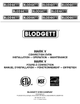
Lifting eyes are supplied for purpose of
installation and servicing. ' &'* +) %'*'(
$ $ ) !'( $#!*#&" % &) Normal care
should be exercised to prevent mechaniĆ
cal damage to the seal, the frame and the
insulated cable.
Surface temperature of motor
enclosure may reach temperatures which can
cause discomfort or injury to personnel acciĆ
dentally coming into contact with hot surĆ
faces. (When installing, protection should be
provided by user to protect against accidental
contact with hot surface) .
On initial start up the motor and pump should
be checked for proper rotation prior to final
application.
The unit is designed to protect all power connecĆ
tions against moisture. All Reliance Submersible
Pump Motors have a lead connection chamber.
- THREE PHASE dual voltage motors have 9
motor leads and SINGLE PHASE dual voltage
motors have 8 motor leads in this chamber. All
Submersible Pump Motors have 2 thermal proĆ
tector leads and 2 moisture sensing probe leads
in this chamber.
Leads are tagged for easy identification. A conĆ
nection diagram is provided in the lead chamber.
Motors can be connected for either high or low
voltages. (Some motor ratings are built as single
voltage units and as such are not reconnectable).
The motor lead cable assembly for all
Submersible Pump Motors has 3 marked power
leads plus two ground leads, two thermal leads
and two moisture sensing probe leads in
standard cable lengths of 25 feet.
Leads are brought through an epoxy sealed conĆ
nector providing a mechanically strong water tight
seal. The cap and cable assembly are available
from Reliance Electric as a replacement part asĆ
sembly. When replacing the lead wire cap, care
should be taken not to nick or damage the O" ring
seal. Replace any damaged or nicked O" rings.
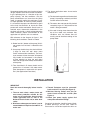
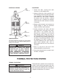
,
LIFT MOTOR ONLY USING BOTH ATTACHMENT POINTS.
EYENUTS & EYEBOLTS MUST BE SEATED & IN LINE AS
SHOWN BELOW.
PREFERRED METHOD - USE SPREADER BAR.
4
692.FF
45°
MAX.
3
With proper application and installation of
monitoring devices, periodic inspection of motor
seals is not required. Should a malfunction occur
the motor has been equipped with a moisture
detection system and thermal protection which
will provide advance warning of impending
failure allowing the user to plan a maintenance
program before failure occurs.
1. Reliance Submersible Motors utilize an
explosionĆproof Class I, Groups C and D,
tandem seal design, with an oil chamber
separate from the winding area.
6. When replacement cable assembly is
required, order from Reliance Electric
Industrial Co. using motor identification
number.
U/L listed motors must be returned to an
authorized Reliance Electric Service Facility for
repairs other than to replace the outer seal. (See
note on Table of Content page.)
To inspect the outer seal proceed as follows:
1. Remove outer snap ring (3), replace as
needed.
2. Wound Stators - Reliance Submersible MoĆ
tors utilize a wound stator which has been
pressed into the frame. The stator insulation
system has been designed for the temperaĆ
ture and electrical rating involved. If the motor
failure is analyzed to encompass a winding
failure, return the motor to an authorized ReĆ
liance Electric Service Shop.
3. Encapsulated Lead Connector Assembly The lead connector assembly has been
especially encapsulated to insure integrity of
the motor. The connector can be removed
from the motor in order to reconnect leads.
Should the lead connector assembly be
damaged or the integrity of the encapsulation
be in question, it is required that a replaceĆ
ment lead connector assembly be ordered
from Reliance Electric Company.
MOTOR MAY CONTAIN GAS UNDER
PRESSURE DUE TO HIGH TEMPERATURES FROM OPERATION WITHOUT
BEING SUBMERGED.
DISASSEMBLY
MAY CAUSE BODILY INJURY. FOR ASSISTANCE CONTACT A RELIANCE OFFICE.
4. Hardware - All hardware is stainless steel
and should be replaced with the same type.
5. If the Conduit Connection is used, a corrosion
resistant conduit such as stainless steel is
recommended.
2. Remove rotating outer seal (4), replace as
needed.
3. Approved lubricating and insulating oil shall
meet Reliance approved source sheet 4824Ć
18ĆAF. Manufacturer's materials currently
meeting this specification are as follows:
ITEM
MANUFACTURER
MANUFACTURER'S
IDENTIFICATION
OF MATERIAL
1
Sun Oil Company
Sun Fleet Regular SAE 10W
2
Standard Oil Co.
Sohio 62 SAE 10W
3
Shell Oil Company
Rotella 10 SAE 10W
After assembly, run motor in shaft down position
for 30 seconds minimum to one minute
maximum to allow seals to seat; then check for
oil leakage. In some cases, a slight oil mist will
appear around the seal. Wipe clean after test.
Before painting motor, cover exposed seal.
Remove any paper, tape, etc., from seal area
before crating motor. These motors can be
shipped in shaft up or shaft down position. Care
must be taken that exposed seal is not damaged
during shipment. Carton must protect exposed
seal from dirt, dust and damage.
4
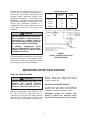
1. Loosen four bolts, securing lead cable
connector (1), two complete turns.
CABLE
CONNECTOR
2. Attempt to break the cable connector seal
thus relieving gas pressure within the motor.
If gas pressure is not relieved loosen the
bolts another turn and try again. Continue
this process until the pressure is relieved
and/or the cap is removed. Be extremely
careful until the cable connector assembly
is removed.
MOISTURE
SENSORS (2)
3. Remove cable connector and reconnect to
desired voltage as shown on connection
diagram inside the cable connector.
OUTER SEAL
OUTER SNAP
RING
The cable connector assembly may be removed
to reconnect the leads without negating the U/L
listing or the warranty.
4. Insulate connectors with 4824Ć13ĆAU heat
shrinkable plastic. If the 4824Ć13ĆAU shrinkĆ
able plastic is not available, tape may
be used, but it should be an oil resistant
type. Enough wraps should be used to
insure the buildup will be sufficient to prevent
the connector from breaking through the
insulation. The following procedure should
be employed: Five layers of plastic elecĆ
trical tape followed by two layers electrical
grade woven adhesive tape, such as
Mystik 7020 or 3M #27, for oil and abrasion
resistance.
5. Place O" ring over fit and coat fit with
Chevron SRI grease (not excessive).
MOTOR MAY CONTAIN GAS UNDER
PRESSURE DUE TO HIGH TEMPERATURES FROM OPERATION WITHOUT
BEING SUBMERGED. DISASSEMBLY
MAY CAUSE BODILY INJURY. FOR ASSISTANCE CONTACT A RELIANCE OFFICE.
6. Place cable connector back on motor, install
four bolts, and tighten.
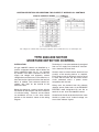
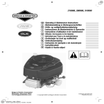
Thermostat leads marked P1 & P2 must be conĆ
nected in series with the stop button of the 3Ćwire
pilot circuit of the magnetic motor controller, so
that the thermostat will open the circuit before
dangerous temperatures are reached.
'$% '" !&!$% $
#'"" )& &$ "$!&&! (%
'$ &! "$!"$* ! & !$ '&+ &%
%*%& (!% !&!$ )$$ &*
5
Alternating Current
Thermostats are automatic reset for use in a
normally closed circuit where the thermostat is
connected in series with the holding coil of the
magnetic starter. Thermostats provide Over
Temperature Protection 2" in accordance with
NEMA MG 1Ć12.53. When the motor is so marked
locked rotor protection is not provided by the
winding over temperature protector. It is
suggested that over current protection be used
in the motor starter to insure locked rotor
protection.
!
Volts
Continuous
Amperes
Inrush
Amperes
110Ć120
3.0
30
220Ć240
1.5
15
440Ć480
0.75
7.5
550Ć600
0.6
6.0
STARTER
P1
AĆC LINE
P2
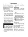
WARNING
(2)
STOP
MOTOR CONTROLLER MAY HAVE AUTOMATIC OR MANUAL OVERLOAD RESET.
DISCONNECT ALL POWER LEADS TO
MOTOR WHEN PERFORMING ANY WORK
ON MOTOR OR DRIVEN EQUIPMENT.
(1)
L1
L2
L3
AĆC LINE
START
T1 T2 T3
GRD
P2
MOTOR
P1
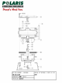
A MANUAL, MOMENTARY START
SWITCH IS REQUIRED TO PREVENT AUTOMATIC RESTART OF MOTOR WHEN
THERMOSTAT RESETS.
P1 & P2 Normally Closed Thermostat Leads
(normally open thermostats are not acceptable to UL)
(1) Starter Holding Coil
(2) Holding Coil Contacts - N.O.
THERMOSTATS
FIGURE 2
TYPICAL THERMAL PROTECTOR
WIRING DIAGRAM
If current through the thermostat will exceed the
values listed in Figure 2 an intermediate control
circuit relay must be used to reduce the current
or the thermostat will not work properly.
MOISTURE DETECTION SYSTEM
MOISTURE SENSING PROBES
!
IMPORTANT
Reliance Submersible Pump Motors are
equipped
with
moisture
detection
devices. Failure to properly connect or
utilize this system voids motor warranty.
Moisture sensing probes, leads marked W1, and
W2, must be used in conjunction with an
induction relay. This device will detect moisture
entering the oil chamber due to failure of the
outer seal and, when properly connected to a
warning device, will provide notification of
needed maintenance. Integrity of system
requires periodic test.
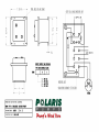
CONTROLS AND SIGNAL DEVICES
A control and signal device (not supplied by
Reliance) must be installed at the job site to
complete the moisture detection system.
Compatible controls are available from:
Charles F. Warrick Co., Normandy Court,
Royal Oak, Michigan 48073, (810) 549Ć4900.
6
"& .'$, + * &'%"&$ .$-+ & %0 &0/!* *'% &'%"&$ %"&-+ ,' &'%"&$ ($-+ $$ ,0( 2 '&,*'$+ * "&,"" 0 +("" '%('&&, &-%* /!"! '$$'/+ ,!
'*%, 2 /!* ,! + * *($
0&-%*+ & $,,*+ "&",". ' ,! 2
+-(($0 $"& .'$, & *)-&0 '&,,
'&" -*,"'& & &$'+-* ! '&,*'$ !+ , $$ '& ,! *" !, !& +" ' ,! ,*%"&$
$'# & ","'& ! &$'+ '&,*'$ !+
&',!* , $$ '& ,! '-,+" ' ,!
&$'+-* '.*
'-&, ,! '&,*'$ '& .*,"$ +-* /",! ,!
,*&+'*%* '& ,! $, !& +" & '%($"+!
$$ "&", /"*"& *%"&$+ '& ,! '&,*'$
*&-%* & * "& ,! +% *$,".
('+","'& + ,! ,*%"&$+ +!'/& '& ,! /"*"&
" *%
*%"&$ ("* 2
%-+, '&,"&-'-+$0 &* "1
*'% & 2 +-(($0 $"& ' $,*"$ !*,*2
"+,"+ +!'/& '& ,! , $$
'&,,+ %-+, /"* "&,' ,! $,*"$ $'
"*-",+ ' ,! /*&"& ."+ + *)-"*
! '&,, -+ '* $' -,0 %-+, /"*
"& +*"+ /",! ,! $' & ,!, +*"+ *&!
"*-", '&&, *'++ ('/* +'-*
'%(,"$ /",! ,! $'
"*"& %-+, (*'." *'% ,! %'"+,-*
,,'* +&+'* (*' $+ ' ,! %','* +" &, & ,'
,*%"&$+ & ' ,! 2 '&,*'$
'&,*'$ $+ +!'-$ &', "&+,$$ "& ,! +%
'&-", + ('/* $+ &- .'$, &
-+ $+ %'"+,-* +" &$+
Normally open load contacts close and normally
closed load contacts open when the sensor
probes detect the influx of moisture within the
motor.
#
A normally closed pushbutton and neon
indicating lamp are provided as means of
checking the moisture sensing components.
#
When the pushbutton is depressed, the
indicating lamp will be illuminated to indicate (A)
power is supplied to the control, (B) the control
is operative, and (C) wiring to the moisture
sensing probes in the motor is intact. This
procedure should be performed periodically to
confirm integrity of circuit.
!
#
!
The signal device may be audible (bell, buzzer,
horn or siren) or visible (incandescent or neon
lamp) or both - a signal device of your choice
may be obtained from your local electrical supply
house.
"
# # It is recommended that upon indication (by warnĆ
ing light, etc.,) of outer seal failure that the motor
be removed from the installation and the oil and
outer seal be replaced as soon as possible.
"
"
WIRING BY WARRICK
WIRING BY OTHERS
CONTROL ENCLOSURE
If reconditioning is not performed within a 30 day
period it is recommended that the inner seal be
thoroughly inspected and replaced if required.
#"
When ordering parts or reporting trouble give
Sales Office complete Nameplate Data.
Power
Cable
Control Cable
"
Polyphase
T1
T2
T3
Ċ
Ground
Single
Phase
T1
T4
TA
Ċ
Ground
All
P1
P2
W1
W2
Ground
8
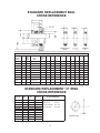
STANDARD REPLACEMENT SEAL
CROSS REFERENCE
PURCHASING SPECIFICATIONS
a
Crane
Type
Seal
b
c
d
k
m
2
2
1- %."*'$
2
2
2
2
2
2
2
1- %."*'$
2
2
2
2
2
2
2
1- %."*'$
2
2
2
2
2
2
2
1- %."*'$
2
2
2
2
2
2
1- %."*'$
2
2
2
2
2
2
2
1- %."*'$
2
2
1- %."*'$
2
2
1- %."*'$
2
2
1- %."*'$
2
2
1- %."*'$
Part No.
64262Ć
Type
Seat
Spring
Code
No.
e
f
g
h
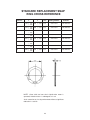
STANDARD REPLACEMENT O" RING
CROSS REFERENCE
Part No.
421900
I.D.
Nominal
W.
UL Listed
Material
Approved Suppliers and
Compound Number
2!
2!
! ! "0',+") %")
, 2
".(%. %")
22
2!
! .%$'/',+ 1##%.
, 2!
! ."+% "$('+&
, 2!
! 2!
! 2!
! 2!
! 2!
! 2!
! ! 2 #% "
((
$
% " &!#
!#$
&
&&
$ "!##
% &
&&
$ "!##
% &
&&
$ "!##
% &&
$ "!##
% &
&&
$ "!##
% &
&&
$ "!##
% &
&
$ "!##
% &
&
&
$ "!##
% %
'
ENGINEERING STANDARD PROCEDURE
IMPELLER INSTALLATION – TECH BULLETIN
DOCUMENT NBR. :
REVISION:
PED-016
1of 2
EFFECTIVE
DATE:
1
09-26-2003
1.0
SCOPE: The purpose of this Engineering Standard Document is to define the procedure to be
followed in installing the Impeller and Impeller Lock Screw.
2.0
METHOD:
2.1 – Impeller Installation
Clean all parts prior to impeller installation.
Apply “Never Seize” or similar to Impeller bore, Shaft and
Key.
Install Impeller onto Shaft. Using a grease remover or
solvent, remove all grease, oil or preservative from the shaftend internal threads and dry.
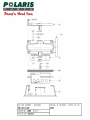
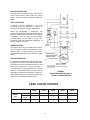
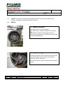
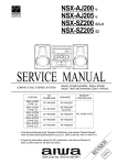
2.2 – Impeller Blocking
Position an Open End or Box / Open End Wrench Using one
of the Strainer Bolts as shown. Place a piece of Wood
between the Impeller and Wrench.
Note: Reverse Wrench Location to opposite side for Impeller
removal.
0
1
REV
ECN
NEW
ADDED250LH
CHANGE DESCRIPTION
UJB
UJB
BY
APPV’D
08-15-02
09-26-03
DATE
ENGINEERING STANDARD PROCEDURE
IMPELLER INSTALLATION – TECH BULLETIN
DOCUMENT NBR. :
REVISION:
PED-016
2of 2
EFFECTIVE
DATE:
1
09-26-2003
2.3 – Impeller Cap Installation
Remove all oil or grease from Impeller Screw. Install O-rings
onto Impeller Screw and Impeller Cap (Model PHO) or Shaft
Adapter (Models PBO, PVO).
Insert Impeller Screw and apply Thread Locker to the
Impeller Screw and shaft-end internal threads.
Use Devcon SuperLock 2271 High Strength Stud Lock
Grade or equivalent.
2.4 – Lock Screw Installation
Align and insert the Impeller Cap or Shaft Adapter into the
Impeller Counter Bore. Insert the Lock Screw into Motor
Shaft and tighten using a Torque Wrench or Allen Wrench
with suitable extension.
See Table below for required Torque.
2.5 - Impeller Lock Screw Torque Requirements
0
1
REV
ECN
NEW
ADDED250LH
CHANGE DESCRIPTION
TBM 50LH – 100LH
TBM 150LH
TBM 200LH
TBM 250LH
(1/2”-13 UNC)
(5/8”-11 UNC)
(3/4”-10 UNC)
(3/4”-10 UNC)
55 ft/lbs (75 Nm)
110 ft/lbs (150 Nm)
200 ft/lbs (275 Nm)
200 ft/lbs (275 Nm)
TBM 75MH
TBM 100MH
TBM 150MH
TBM 200MH
(5/8”-11 UNC)
(5/8”-11 UNC)
(3/4”-10 UNC)
(3/4”-10 UNC)
110 ft/lbs (150 Nm)
110 ft/lbs (150 Nm)
200 ft/lbs (275 Nm)
200 ft/lbs (275 Nm)
UJB
UJB
BY
APPV’D
08-15-02
09-26-03
DATE
ENGINEERING STANDARD PROCEDURE
IMPELLER INSTALLATION – TECH BULLETIN
DOCUMENT NBR. :
REVISION:
PED-017
1.0
1of 1
EFFECTIVE
DATE:
0
09-16-2003
SCOPE:
Assembly Pre-Load / Bolt Torque requirements for Metric Fasteners of Grades A2-70 (304L)
A4-70 (316L) and 8.8, for Sizes M4 to M20.
2.0
METHOD:
ASSEMBLY TORQUE / ASSEMBLY PRE-LOAD
SIZE
TIGHTENING TORQUE
CLASS
ASSEMBLY PRE-LOAD
lb/ft [lb/in]
kN
lbf
M4
2.20
1.622 [19.46]
2.73
612.23
M5
4.20
3.097 [37.16]
4.47
1002.44
7.40
5.45 [65.40]
6.31
1415.08
17.80
13.12
11.60
2601.42
36.00
26.54
18.40
4126.40
62.00
45.72
26.90
6032.62
M16
150.00
110.62
50.90
11414.88
M20
303.00
223.45
82.00
18389.40
M6
M8
M10
M12
A2-70, A4-70, 8.8
Nm
ABOVE TORQUE / PRE-LOAD VALUES ARE BASED ON A COEFFICIENT OF FRICTION OF 0.14 (Anti-seize Lubricant)
0
1
REV
ECN
NEW
ADDED250LH
CHANGE DESCRIPTION
UJB
UJB
BY
APPV’D
08-15-02
09-26-03
DATE