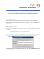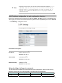
1
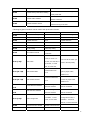
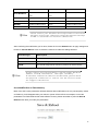
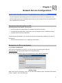
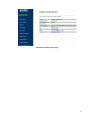
VoIP Analog Telephone Adapter VIP-156/VIP156PE/VIP-157/VIP-157S User’s manual Version 3.1 1 Copyright Copyright (C) 2008 PLANET Technology Corp. All rights reserved. The products and programs described in this User’s Manual are licensed products of PLANET Technology, This User’s Manual contains proprietary information protected by copyright, and this User’s Manual and all accompanying hardware, software, and documentation are copyrighted. No part of this User’s Manual may be copied, photocopied, reproduced, translated, or reduced to any electronic medium or machine-readable form by any means by electronic or mechanical. Including photocopying, recording, or information storage and retrieval systems, for any purpose other than the purchaser's personal use, and without the prior express written permission of PLANET Technology. Disclaimer PLANET Technology does not warrant that the hardware will work properly in all environments and applications, and makes no warranty and representation, either implied or expressed, with respect to the quality, performance, merchantability, or fitness for a particular purpose. PLANET has made every effort to ensure that this User’s Manual is accurate; PLANET disclaims liability for any inaccuracies or omissions that may have occurred. Information in this User’s Manual is subject to change without notice and does not represent a commitment on the part of PLANET. PLANET assumes no responsibility for any inaccuracies that may be contained in this User’s Manual. PLANET makes no commitment to update or keep current the information in this User’s Manual, and reserves the right to make improvements to this User’s Manual and/or to the products described in this User’s Manual, at any time without notice. If you find information in this manual that is incorrect, misleading, or incomplete, we would appreciate your comments and suggestions. CE mark Warning The is a class B device, In a domestic environment, this product may cause radio interference, in which case the user may be required to take adequate measures. WEEE Warning To avoid the potential effects on the environment and human health as a result of the presence of hazardous substances in electrical and electronic equipment, end users of electrical and electronic equipment should understand the meaning of the crossed-out wheeled bin symbol. Do not dispose of WEEE as unsorted municipal waste and have to collect such WEEE separately. Trademarks The PLANET logo is a trademark of PLANET Technology. This documentation may refer to numerous hardware and software products by their trade names. In most, if not all cases, their respective companies claim these designations as trademarks or registered trademarks. 2 Revision User’s Manual for PLANET VoIP Analog Telephone Adapter: Model: ATA Rev: 3.1 (2008, February) Part No. EM-VIP_ATAV3.1 3 TABLE OF CONTENTS Chapter 1 ................................................................................................................................... 6 Introduction .............................................................................................................................. 6 Overview....................................................................................................................................................... 6 Package Content .......................................................................................................................................... 7 Physical Details ............................................................................................................................................ 7 LED Display & Button....................................................................................................................... 10 Chapter 2 Preparations & Installation................................................................................. 12 Physical Installation Requirement............................................................................................................ 12 LAN IP address configuration via web configuration interface ......................................................... 13 Chapter 3 Network Service Configurations......................................................................... 17 Configuring and monitoring your ATA from web browser .................................................................... 17 Overview on the web interface of ATA .............................................................................................. 17 Manipulation of ATA via web browser............................................................................................... 17 Chapter 4 VoIP Telephone Adapter Configurations............................................................ 19 Phone Book ........................................................................................................................................ 19 Call Forward....................................................................................................................................... 20 SNTP settings ..................................................................................................................................... 22 Volume Setting ................................................................................................................................... 22 Block Setting ...................................................................................................................................... 23 Auto Answer (For VIP-157) ............................................................................................................... 24 Caller ID settings................................................................................................................................ 24 Dial Plan Settings ............................................................................................................................... 25 Flash Time Setting.............................................................................................................................. 27 Call waiting Settings .......................................................................................................................... 27 T.38 (FAX) Settings............................................................................................................................ 28 Hot line Settings ................................................................................................................................. 28 Alarm Settings.................................................................................................................................... 29 LAN Settings...................................................................................................................................... 29 PC Settings ......................................................................................................................................... 30 DDNS Settings ................................................................................................................................... 31 VLAN Settings ................................................................................................................................... 32 DMZ Settings ..................................................................................................................................... 33 Virtual Server ..................................................................................................................................... 33 PPTP Settings ..................................................................................................................................... 34 Service Domain Settings .................................................................................................................... 35 Port Settings ....................................................................................................................................... 36 Codec Settings.................................................................................................................................... 36 4 Codec ID Setting ................................................................................................................................ 37 DTMF Setting .................................................................................................................................... 38 RPort Settings..................................................................................................................................... 38 Other Settings..................................................................................................................................... 39 STUN settings .................................................................................................................................... 39 Auto Configuration............................................................................................................................. 40 PTT Settings ....................................................................................................................................... 40 Cancel without to tag.......................................................................................................................... 41 MAC CIone Setting............................................................................................................................ 41 Tone Settings ...................................................................................................................................... 43 Advanced Settings.............................................................................................................................. 43 System Authority................................................................................................................................ 44 Save & Reboot ................................................................................................................................... 45 Firmware Upgrade.............................................................................................................................. 45 Auto Upgrade ..................................................................................................................................... 46 Reset to Default .................................................................................................................................. 47 Reboot without saving........................................................................................................................ 47 Appendix A Voice Communication Samples......................................................................................... 49 Case 1: ATA to ATA connection via IP address .................................................................................. 49 Case 2: (Peer-to-Peer mode) VIP-157S Port 1 to Port 2 communications ......................................... 50 Case 3: Voice communication via SIP proxy server – SIP-50 ............................................................ 51 Case 4: Voice communication via IP PBX system – IPX-2000 (Auto-config)................................... 53 Case 5: Call Forward Feature_Example 1.......................................................................................... 57 Case 6: Call Forward Feature_Example 2.......................................................................................... 59 Case 7: Call Forward Feature_Example 3.......................................................................................... 61 Case 8: Call Forward Feature_Example 4.......................................................................................... 63 Case 9: Auto Answer Feature_IP to PSTN ......................................................................................... 64 Case 10: Auto Answer Feature_PSTN to IP....................................................................................... 66 Appendix B The method of operation guide ............................................................................................ 68 Call Transfer....................................................................................................................................... 68 3-Way Conference .............................................................................................................................. 68 Call Waiting........................................................................................................................................ 68 Switch the Realm (Registration Proxy Server)................................................................................... 68 Auto Update firmware by manual (Keypad) ...................................................................................... 69 Appendix C VIP-156/VIP-156PE/VIP-157/VIP-157S Specifications..................................................... 70 5 Chapter 1 Introduction 1 Overview Based on years of VoIP manufacturing experiences, PLANET Technology VoIP total solutions are known for advanced implementation of standards based telephony with mass deployment capability. Cost-effective, easy-to-install and simple-to-use, the PLANET VIP-156/VIP-157/VIP-157S VoIP Phone Adapter (“ATA” in the following term) converts standard telephones to IP-based networks. The service providers and enterprises offer users traditional and enhanced the telephony communication services via the existing broadband connection to the Internet or corporation network. With the ATA, home users and companies are able to save the installation cost and extend their past investments in telephones, conference and speakerphones. The ATA can be the bridge between traditional analog systems and IP network with an extremely affordable investment. The ATA includes two alternatively Ethernet interface for Internet (PPPoE, DHCP or Fixed IP), or office LAN connection. With adding the auto-provision feature of our IP PBX product - IPX-2000, the ATA can be seamlessly integrated into the telephony network and be used in consumer and business IP telephony service, no expertise required! The ATA and our IP PBX system integration are the ideal combination for your office daily communications. Product Features • Feature-rich telephone service over home or office Internet/Intranet connection • Auto-config feature for flexible, ease-of-use IP PBX system integration • Cost effective, field proven compatibility, and stability • Web-based and telephone keypad machine configuration • Remote machine administration authentication • Voice prompt for machine configurations VoIP Features • SIP 2.0 (RFC3261) compliant • Peer-to-Peer / SIP proxy calls • Voice codec support: G.711, G.723.1, G.729A/G.729B • T.38 FAX transmission over IP network 6 • Voice processing: Voice Active Detection, DTMF detection/ generation, G.168 echo cancellation (16mSec.), Comfort noise generation (CNG) • In band, out-of-band, and SIP-info DTMF support Package Content The contents of your product should contain the following items: VoIP Telephone Adapter Power adapter Quick Installation Guide User’s Manual CD RJ-11 cable x 1 Physical Details The following figure illustrates the front/rear panel of ATA. Respective model/descriptions are shown below: VIP-156: SIP Analog Telephone Adapter VIP-156PE: 802.3af PoE SIP Analog Telephone Adapter VIP-157: 1 FXS/ 1 FXO SIP Analog Telephone Adapter VIP-157S: 2-port FXS SIP Analog Telephone Adapter Front Panel of VIP-156 7 Left / Right Panel of VIP-156 Front Panel of VIP-156PE Left / Right Panel of VIP-156PE 8 Front Panel of VIP-157 Left / Right Panel of VIP-157 Front Panel of VIP-157S 9 Left / Right Panel of VIP-157S LED Display & Button 1 PC RJ-45 connector, to maintain the existing network structure, connected directly to the PC through straight CAT-5 cable RJ-45 connector, for Internet access, connected directly to Switch/Hub through straight CAT-5 cable. 2 LAN The LAN interface also can be connected with 802.3af PoE switch or converter for power supply (VIP-156PE) 3 12V DC 4 Reset ÍNote 12V DC Power input outlet Reset to the factory default setting Machine default IP is http://192.168.0.1. Press RESET button on rear panel over 5 seconds will reset the VoIP Phone Adapter to factory default value. (Except speed dial and call forward settings) 10 LED display of VIP-156 / VIP-156PE LED Indicators Descriptions PWR Power is supplied to the device. STATUS The Status LED will be flashing when the machine is operational LNK/ACT OFF: the device is connected to LAN at 10Mb/s. ON: the device is connected to LAN at 100Mb/s. RING OFF: the phone is idle. ON: the phone is in use (offhook). Blinking: the phone is ringing. LED display of VIP-157 / VIP-157S LED Indicators Descriptions STATUS The Status LED will be flashing when the machine is operational LNK/ACT OFF: the device is connected to LAN at 10Mb/s. ON: the device is connected to LAN at 100Mb/s. RING 1 OFF: the phone is idle. ON: the phone is in use (offhook). Blinking: the phone is ringing. RING 2 OFF: the phone is idle. ON: the phone is in use (offhook). Blinking: the phone is ringing. 11 Chapter 2 Preparations & Installation 2 Physical Installation Requirement This chapter illustrates basic installation of ATA analog Phone Adapter ((“ATA” in the following term)) • Network cables. Use standard 10/100BaseT network (UTP) cables with RJ45 connectors. • TCP/IP protocol must be installed on all PCs. For Internet Access, an Internet Access account with an ISP, and either of a DSL or Cable modem Administration Interface PLANET ATA provides GUI (Web based, Graphical User Interface) for machine management and administration. Web configuration access To start ATA web configuration, you must have one of these web browsers installed on computer for management • Microsoft Internet Explorer 6.0.0 or higher with Java support Default LAN interface IP address of ATA is 192.168.0.1. You may now open your web browser, and insert http://192.168.0.1 in the address bar of web browser to logon ATA web configuration page. ATA will prompt for logon username/password, please enter: root / null (no password) to continue machine administration. 12 ÍNote Please locate your PC in the same network segment (192.168.0.x) of ATA. If you’re not familiar with TCP/IP, please refer to related chapter on user’s manual CD or consult your network administrator for proper network configurations. LAN IP address configuration via web configuration interface Execute your web browser, and insert the IP address (default: 192.168.0.1) of VIP in the adddress bar. After logging on machine with username/password (default: root / no passwrd), browse to “Network” --> “LAN Settings” configuration menu: Parameter Description IP address LAN IP address of ATA Default: 192.168.0.1 Subnet Mask LAN mask of ATA Default: 255.255.255.0 Default Gateway Gateway of ATA Default: 192.168.0.254 Network settings via Keypad commands The ATA series phone adapters support telephone keypad configurations, please connect analog telephone set and refer to the following table for machine network configurations. IVR Menu Choice #111# Machine operation Set DHCP client Parameter(s) None Notes: ATA will change to DHCP 13 Client #112xxx*xxx*xxx* Setup Static IP Address xxx# Use the * (star) key DHCP will be disabled and when entering a decimal system will change to the point. Static IP type. Use the * (star) key #113xxx*xxx*xxx* Set Network Mask xxx# when entering a decimal Must set Static IP first. point. Use the * (star) key #114xxx*xxx*xxx* Set Gateway IP Address xxx# when entering a decimal Must set Static IP first. point. Use the * (star) key #115xxx*xxx*xxx* Set Primary DNS Server xxx# when entering a decimal Must set Static IP first. point. Must unlock the protect function before set up #190# Unlock None network settings and ATA function via keypad. The system will be lock #191# Lock None and can’t set up network settings via keypad. #195# The system will reboot Reboot None automatically. The system will be reset to #198# Factory Reset None factory default value and reboot automatically. 0* To switch PSTN mode None VIP-157 only Following keypad commands can be used to display the network settings enabled on ATA via voice prompt. IVR Menu Choice Machine operation Notes: IVR will announce the current PC-port IP #120# Check PC IP Address #121# Check network connection Type #122# Check the Phone Number #123# Check Network Mask #124# Check Gateway IP Address address of the ATA. IVR will announce if DHCP in enabled or disabled. IVR will announce current enabled VoIP number. IVR will announce the current network mask of the ATA. IVR will announce the current gateway IP 14 address of the ATA. IVR will announce the current setting in the #125# Check Primary DNS Server Setting #126# Check LAN IP Address #128# Check Firmware Version Primary DNS field. IVR will announce the current LAN port IP address of the ATA. IVR will announce the version of the firmware running on the ATA. Following keypad commands can be used to set up the main function . IVR Menu Choice Machine operation Parameter(s) Notes: #138# Enable call waiting None Enable Call waiting #139# Disable call waiting None Disable Call waiting #160# Update firmware None Update firmware #510# Blind Transfer ATA Bland Transfer #511# Attendant Transfer ATA Attendant Transfer #512# 3-way calling ATA 3-way calling #514# IP transfer to PSTN ATA transfer IP call to PSTN side 1:G.711 u-Law, 2: G.711 a-Law, 3: G.723.1, 4: You can set the codec you #130+[1~8]# Set Codec G.729a, 5: G.726 16K, 6: want to the first priority. G.726 24K, 7: G.726 32K, 8: G.726 40K, You can set the Handset Handset Gain from #131+[00~15]# Set Handset Gain gain to proper value, 0~15 default is 10 You can set the Handset Handset Volume from #132+[00~12]# Set Handset Volume volume to proper value, 0~12 default is 10 #135xxx*xxx*xxx* xxx# #136xxx*xxx*xxx* Set Auto config TFTP You can set the TFTP Server IP Address Server IP address Set Auto config FTP You can set the FTP Server IP Address Server IP address TFTP Server IP Address FTP Server IP Address xxx# You can set the Auto #137+[0~2]# 0: Disable, 1: TFTP configuration mode, 0: mode, 2: FTP mode Disable, 1: use TFTP Auto config mode Server, 2: user FTP Server #145# Forward function disable Disable forwrad funciton #146+Number# enable forward to FXS Eanble forward to FXS 15 Port Port enable forward to FXO Eanble forward to FXO Port Port #116# Enable PPTP function None Enable PPTP function #117# Disable PPTP function None Disable PPTP function #118# Enable VLAN function None Enable VLAN function #119# Disable VLAN function None Disable VLAN function #147+Number# L Hint Please contact your Internet service provider to obtain the Internet access type, and select the proper network settings in ATA to establish the network connections. After confirming the modification you’ve done, Please click on the Submit button to apply settings and browse to “Save & Reboot” menu to reboot the machine to make the settings effective. Connection Type Data required. Fixed IP In most circumstances, it is no need to configure the DHCP settings. DHCP clinet The ISP will assign IP Address, and related information. PPPoE The ISP will assign PPPoE username / password for Internet access, L Hint Please consult your ISP personnel to obtain proper PPPoE/IP address related information, and input carefully. If Internet connection cannot be established, please check the physical connection or contact the ISP service staff for support information. Save Modification to Flash Memory Most of the VoIP router parameters will take effective after modifications, but it is just temporary stored on RAM only, it will disappear after your reboot or power off the VoIP Phone Adapter, to save the parameters into Flash ROM and let it take effective forever, please remember to press the Save & Reboot button after you modify the parameters. 16 Chapter 3 Network Service Configurations 3 Configuring and monitoring your ATA from web browser The ATA integrates a web-based graphical user interface that can cover most configurations and machine status monitoring. Via standard web browser, you can configure and check machine status from anywhere around the world. Overview on the web interface of ATA With web graphical user interface, you may have: More comprehensive setting feels than traditional command line interface. Provides user input data fields, check boxes, and for changing machine configuration settings Displays machine running configuration To start ATA web configuration, you must have one of these web browsers installed on computer for management Microsoft Internet Explorer 6.0.0 or higher with Java support Manipulation of ATA via web browser Log on ATA via web browser After TCP/IP configurations on your PC, you may now open your web browser, and input http://192.168.0.1 to logon Phone Adapter web configuration page. Phone Adapter will prompt for logon username/password: root / null (no password) ATA log in page When users login the web page, users can see the Phone Adapter system information like firmware version, company…etc in this main page. 17 VoIP Phone Adatper main page 18 Chapter 4 VoIP Telephone Adapter Configurations 4 Phone Book ATA can set up 140 records of Phone Book. User can dial the Name records to make calls via Phone Book feature. Field Phone Book Page Phone Name URL Select Description The default is Page 1. It can select Page1 ~ Page 14 to look round Phone Book records. The record number from 0 ~ 139, it can set up 140 records in total. The name of Phone Book records, it only can input numerals. Fill in the outgoing number (Line Number) or IP address. To select this record. 19 If you need to add a phone number into the Phone Book list, you need to input the position, the name, and the phone number (by URL type). When you finished a new phone list, just click the “Add Phone” button. If you want to delete a phone number, you can select the phone number you want to delete then click “Delete Selected” button. If you want to delete all phone numbers, you can click “Delete All” button. For Example: Ex_1: ATA had added the above phone numbers. User pick up the handset and dial the “301” to make the P2P call ([email protected]). Ex_2: Users pick up the handset and dial the “206” to make the Proxy call (17476433364). Ex_3: Users pick up the handset and dial the “202” to make the P2P call (192.168.1.2:5062). Call Forward This page defines Call Forward function. You can setup the phone number you want to forward in this page. There are three type of Forward mode. You can choose All Forward, Busy Forward, and No Answer Forward by click the icon. All Forward: All incoming call will forward to the number you chosen. You can input the name and the phone number in URL field. If you select this function, then all the incoming call will direct forward to the 20 speed dial number you choose. Busy Forward: If you are on the phone, the new incoming call will forward to the number you choosed. You can input the name and the phone number in URL field. No Answer Forward: If you can not answer the phone, the incoming call will forward to the number you chosen. You can input the name and the phone number in URL field. Also you have to set the Time Out time for system to start to forward the call to the number you choosed. When you finished the setting, please click the Submit button. Call Forward function for VIP-156/VIP-156PT/VIP-157S Call Forward to PSTN (VIP-157): VIP-157 not only support Call Forward to IP calls, but also can forward the calls to PSTN. You can choose the Call Forward type with PSTN, then input the name and the PSTN number in URL/Number field. 21 Call Forward function for VIP-157 SNTP settings This page defines the primary and second SNTP Server IP Address, to get the date/time information. Also you can base on your location to set the Time Zone, and how long need to synchronize again. When you finished the setting, please click the Submit button. Volume Setting This page defines the Handset Volume, Ringer Volume, and the Handset Gain. When you finished the setting, please click the Submit button. Handset Volume is to set the volume for you can hear from the handset. Handset Gain is to set the volume send out to the other side’s handset. 22 Volume Settings for VIP-154T/VIP-154PT Beside the above settings, VIP-157 also can set the volume of PSTN. PSTN-Out Volume is to set the PSTN volume for you can hear. PSTN-In Gain is to set the volume send out to the other side’s handset. Volume Settings for VIP-157 Block Setting This page defines the Block Setting to keep the phone slience. You can choose Always Block or Block a period. Always Block: All incoming call will be blocked until disable this feature. Block Period: Set a time period and the phone will be blocked during the time period. If the “From” time is large than the “To” time, the Block time will from Day 1 to Day 2. When you finished the setting, please click the Submit button. 23 Auto Answer (For VIP-157) This page defines the Auto Answer function. You can set the Auto Answer function to answer the incoming call by the phone. If the call is come from the IP, then the VIP-157 can let user to redial the call to PSTN phone number. If the call is coming from PSTN, then the VIP-157 can let user to redial to IP Phone number. Auto Answer Counter is to set after the ring count met the number you set then the auto answer will enable. For security issue, You’d better to set the PIN Code. If you have set the PIN code, you will hear a tone to inform you input the PIN Code then you can dial out. Caller ID settings This page defines the device to show Caller ID in your PSTN Phone or IP Phone. There are four selection of Caller ID. You need to base on your environment to set the Caller ID function for FSK or DTMF. 24 Dial Plan Settings This page defines the Dial Plan Setting function. This function is when you input the phone number by the keypad but you don’t need to press “#”. After time out the system will dial directly. Field Description Drop Prefix The rule of add or replace code. If setup as No, it will add the prefix number prior to the identification number. If setup as Yes, it will replace the identification number. Replace rule The prefix number. It only accept the numeral and the max length is 8. + The identification number. It can accept the numeral or symbol and 25 the max length is 40. - Symbol: It only accept the [+], [x] - +: It means as “or”. For example, [123+456+334+5xx] even if [123 or 456 or 334 or 5xx] - x: It is equal to 0~9. For example, [5xx] even if the number begin 5. Dial Now If the dialing number are match with this field, it will dial out and need not to press the “#” key to end the dialing. It accepts the numeral or symbol, and the max length are 124. LNote: The starting number can’t be the “0”. For example, if the number is “0xxxx”, because the starting number is “0”, so that the system will ignore this dial plan. Auto Dial Time Stop dialing after seconds then send dial number out. Use # as send key If setup as Yes, the symtem sill stop to receive the dialing number when receive the [#] key. The system also will to determine the Auto Dial Time, it will carry out the calling if there isn’t receive the digit after the Auto Dial Time. If setup as No, the system just according to the Auto Dial Time to determine the end time. Use * for IP dialing If setup as Yes, the system will look on [*] as [.]. For example, if dial the “192*168*0*100#”, it will dial out as “192.168.0.100#”. If setup as No, it just look on [*] as [*]. For example, if dial the “700*#”, it will dial out as “700*#”. Descriptions of example: Example_1: Drop prefix: No, Replace rule 1: 002, +: 1234+4321 (No limit the digit length) 1. If the dialing number is start as “1234”, it will add the 002 at begin. The real dialing number is [0021234…]. 2. If the dialing number is start as “4321”, it will add the 002 at begin. The real dialing number is [0024321…]. Example_2: Drop prefix: Yes, Replace rule 2: 006, +: 002+003+004 (No limit the digit length) 1. If the dialing number is start as “002”, it will replace 002 by 006. The real dialing number is [006…]. 2. If the dialing number is start as “003”, it will replace 003 by 006. The real dialing number is [003…]. Example_3: Drop prefix: No, Replace rule 3: 007, +: 5xxx+35xx (Has limit the digit length) 1. If the dialing number start as “5” and follow 3 digits, it will add the 007 at begin. The real dialing number is [0075xxx]. 2. If the dialing number start as “35” and follow 2 digits, it will add the 007 at begin. The real dialing number is [00735xx]. 26 Example_4: Dial Now: *xx+#xx+11x+xxxxxx 1. If the dialing number is match with the rule of “*xx”, it will send out the dialing number directly. For example, *00/ *01/ *02…*99. 2. If the dialing number is match with the rule of “#xx”, it will send out the dialing number directly. For example, #00/ #01/ #02…#99. 3. If the dialing number is match with the rule of “11x”, it will send out the dialing number directly. For example, 111/ 112/ 113…119. 4. If the dialing number is match with the rule of 8 digits, it will send out the dialing number directly. For example, 12345678. Flash Time Setting When you use the PSTN Phone and you need to press the Hook to do the Flash (Switch to the other phone line or HOLD), this function is for you to set the time you press the Hook to represent the Flash function. Flash Time Settings for VIP-156/VIP-156PT/VIP-157S Beside the above settings, VIP-157 also can set the flash time of FXO port. Flash Time Settings for VIP-157 Call waiting Settings When you are talking with other people, You can choose If you want to hear the notice when there is a new coming call. If the call waiting function is On, if there is a new incomeing call, you will hear the call 27 waiting notice in your current call. If you set the function to Off, then you will not hear any notice. T.38 (FAX) Settings This page defines the T.38 (FAX) Setting function. You can Enable/Disable the T.38 function, and can modify the T.38 transmission port of each FXS port. T.38 (FAX) Settings for VIP-156/VIP-156PE/VIP-157 T.38 (FAX) Settings for VIP-157S Hot line Settings This page defines the Hot line setting in this page. When user pick up the handset, the device will call to 28 the specific number automatically. Use Hot Line: Click Enable to carry the Hot line function out. Hot line number: The hot line number, it can input the IP address or registration number. Alarm Settings This page defines the Alarm setting in this page. It provides the alarm function, and it can set up the Alarm Time to get the telephone ringed up every day. Alarm: The default is Off. If set up as On, the telephone will ringed up at the specific time. Alarm Time: It can set up the system prompt time with 24 hours. Current time: The next alarm time. LAN Settings This page defines the LAN setting in this page. LAN Mode: The default is Bridge mode, and it also provides NAT mode. - Bridge: When set as is mode, the LAN and PC ports are in the same network segment. - NAT: The LAN and PC ports are in the different network segment, and PC port could enable the DHCP Server function to allot the IP address. IP Type: The default is Fixed IP, and it also provides DHCP Client and PPPoE connection modes. 29 - Fixed IP: It could setup the IP address manual. - DHCP Client: It will acquire the IP address automatically. - PPPoE: It will use the PPPoE connection method. IP: The IP address Mask: The sub net address Gateway: The default gateway address DNS Server1: The default is 168.95.192.1, it could setup the first DNS server address. DNS Server2: The default is 168.95.1.1, it could setup the second DNS server address. MAC: The MAC of LAN port Host Name: The product model User Name: The PPPoE connection account name. It could inpout numeral or character, the maximum date length are 63. Password: The PPPoE connection account password. It could inpout numeral or character, the maximum date length are 63. PC Settings This page defines the PC setting in this page. IP: The IP address of PC port. (In the Birdge mode, the Default IP: 192.168.0.1) Mask: The sub net address. (Default: 255.255.255.0) MAC: The MAC of PC port 30 DHCP Server: It will allot the IP address automatically when enabke this function. Start IP: Start IP of lease table End IP: End IP of lease table. Network device connecting to the PC port can dynamic obtain the IP in the range between start IP and end IP Lease Time: DHCP server lease time DDNS Settings This page defines the DDNS setting in this page. You need to have the DDNS account and input the informations properly. You can have a DDNS account with a public IP address then others can call you via the DDNS account. But now most of the VoIP applications are work with a SIP Proxy Server. When you finished the setting, please click the Submit button. 31 VLAN Settings This page defines the VLAN setting in this page. This function needs to co-operate with network devices which have VLAN function. VLAN Packets: If setup as On, it could receive VLAN messages. VID (802.1Q/TAG): Dispose VLAN ID is add a Tag header after realize enable the VLAN function. The realized voice packets transfer at the same VLAN. The prerequisite is it must the same as VLAN of upper switch. The value range are 2~4094. User Priority (802.1P): To setup the user priority. CFI: To indicate the Canonical Format. - If CFI=1, it means the header label include RIF field, and the NCIF flag valus of RIF will to decide the MAC address is Canonical Format or Non-Canonical Format in frame information. - If CFI=0, it means the header label does not include RIF field, and the MAC address is Canonical Format in frame information. 32 DMZ Settings This page defines the DMZ setting in this page. DMZ: If setup as On, all of packets (expect SIP packets) will send to the specific IP address. DMZ Host IP: The DMZ host IP address. Virtual Server This page defines the Virtual Server setting in this page. You could define 24 virtual service information in this page. When you finished the setting, please click the Submit button. Virtual Server Page: There are total page1 to page 3. It could choose the page which want to go over. Num: The serial number. There are total 24 records from Num 0 to 23. Enable: The activate status. The default is Disable, this record will been activate if enable. Protocol: The TCP or UDP communication protocol. Internal Port: For corresponding the internal port. 33 External Port: For corresponding the external port. Server IP: To input the Server IP address. PPTP Settings This page defines the PPTP setting in this page. You could setup the PPTP Server connection information. When you finished the setting, please click the Submit button. 34 Service Domain Settings In Service Domain Function you need to input the account and the related informations in this page, please refer to your ISP provider. You can register three SIP account in the ATA. You can dial the VoIP phone to your friends via first enable SIP account and receive the phone from these three SIP accounts. First you need click Active to enable the Service Domain, then you can input the following items: Display Name: you can input the name you want to display. Line number: you need to input the User Name get from your ISP. Register Name: you need to input the Register Name get from your ISP. Register Password: you need to input the Register Password get from your ISP. Domain Server: you need to input the Domain Server get from your ISP. Proxy Server: you need to input the Proxy Server get from your ISP. Outbound Proxy: you need to input the Outbound Proxy get from your ISP. If your ISP does not provide the information, then you can skip this item. You can see the Register Status in the Status item. If the item shows “Registered”, then your Phone Adapter is registered to the ISP, you can make a phone call direcly. If you have more than one SIP account, you can following the steps to register to the other ISP. When you finished the setting, please click the Submit button. LNote: ATA can register to three different SIP Proxies at the same time. It can receive any one of different SIP accounts incoming call, and it can switch to any one SIP accounts for making calls through input the switch code. Realm switch code: 1*: Realm 1 2*: Realm 2 3*: Realm 3 35 For example: The default is realm 1, input the 2* (Follow by the # key) from keypad and hang up the telephone set. It will switch to realm 2, and it can make the SIP calls via realm 2. Port Settings This page defines the SIP and RTP port number in this page. Each ISP provider will have different SIP/RTPport setting, please refer to the ISP to setup the port number correctly. When you finished the setting, please click the Submit button. Codec Settings This page defines the Codec priority, RTP packet length, and VAD function in this page. You need to follow the ISP suggestion to setup these items. When you finished the setting, please click the Submit button. 36 Codec ID Setting This page defines the Codec ID. Sometimes 2 VoIP devices with different Codec ID will cause the interopability issue. If you are talking with others got some problems, you may ask the other one what kind of Codec ID he use, then you can change your Codec ID. When you finished the setting, please click the Submit button. 37 DTMF Setting This page defines the RFC2833 Out-Band DTMF, Inband DTMF and Send DTMF SIP Info in this page. To change this setting, please following your ISP information. When you finished the setting, please click the Submit button. RPort Settings This page defines the RPort Enable/Disable in this page. To change this setting, please following your ISP information. When you finished the setting, please click the Submit button. 38 Other Settings This page defines the Hold by RFC, Voice/SIP QoS and other settings in this page. To change these settings please following your ISP information. When you finished the setting, please click the Submit button. Hold by RFC: The default is disable, and to start up communication hold back function (RFC definition). Set enable to start up the Hold by RFC function. Voice QoS (Diff-Serv): The Voice QoS feature. SIP QoS (Diff-Serv): The SIP QoS feature. The QoS setting is to set the voice packets’ priority. If you set the value higher than 0, then the voice packets will get the higher priority to the Internet. But the QoS function still need to cooperate with the others Internet devices. SIP Expire Time: To setup the registration interval time. Use DNS SRV: The default is disable, and use DNS SRV mode. Set enable to use DNS to SRV mode to search the host information. STUN settings This page defines the STUN Enable/Disable and STUN Server IP address in this page. This function can help your Phone Adapter working properly behind NAT. To change these settings please following your ISP information. When you finished the setting, please click the Submit button. 39 Auto Configuration This page defines the Auto Configuration (Auto Provision) setting. ATA supports TFTP, FTP, HTTP and IP PBX auto configuration function in total. In IP PBX Auto Configuration Setting you need to check with your service provider if they have provided this function. Usually this function will be boundle with an IP PBX to use in the office. PTT Settings In PTT Settings is for you to set the Country, different country will have different settings in FXS inter face. 40 PTT Settings for VIP-156/VIP-157S Beside the above settings, VIP-157 also can set country of FXO port. PTT Settings for VIP-157 Cancel without to tag This function can decide the device if send the cancel tag to Proxy Server. If there has the similar symptom that the caller cancel the call before the called answer the call, the called still continue to ring up even the caller has cancel this call. It could try select this function to Yes to avoid the above symptom. MAC CIone Setting This page defines the MAC Clone Enable/Disable. This function will copy the MAC address from NIC (Network Interface Card) which placed in PC to LAN port of ATA. That because some ISP will limit the 41 MAC address for PPPoE dial-up connection. Please refer to the following operate procedures for more understandings to carry out the MAC Clone function. 1. Please login ATA and browse to “Network -> LAN Settings” page. To switch the LAN mode to NAT mode then press Save&Reboot button to save the settings and reboot machine. 2. Please make sure the network cable of your PC directly connect with PC port of ATA, then re-login ATA. (In the NAT mode, the default IP address of PC port is http://192.168.123.1) 3. Please browse to “Advanced Settings -> MAC Clone Setting” page and enable the MAC Clone function. 4. ATA will prompt if sure want to clone the MAC of your PC to the LAN port of ATA. 42 5. After Save&Reboot, the MAC of LAN port will become to PC’s original MAC address. Tone Settings This page defines the Tone settings. This function can setup the related parameters of Dial Tone, Ring Back Tone, Busy Tone, Error Tone and Inser Tone. When you finished the setting, please click the Submit button. Advanced Settings This page defines the advanced functions. When you finished the setting, please click the Submit button. ICMP Not Echo: This function can disable echo when someone ping this device, it can avoid haker try to attack the device. Send Anonymous CID: If enable this function, machine will to start the calling hidden function, and it will not send the related Caller information. (The Registration Server also need support this function) Billing Signal: There are provide three type billing types: Polarity Reversal, Tone_12K and Tone_16K. 43 (The Registration Server also need support this function) CPC Delay: When receive the disconnect signal, machine will to cut the voltage down to 0V after this time. CPC Duration: When starting to cut the voltage down to 0V, machine will to continue this state by this time. Send Flash event: There are provide two flash formats: DTMF Event and SIP Info. SIP Encrypt: There are provide seven encrypt formats: INFINET, AVS, WALKERSUN1, WALKERSUN2, CSF1, CSF2 and GX. (The Registration Server also need support this function) PPPoE retry period: If PPPoE dial-up connection fail, machine will retry the dial-up motion after this time. System Log Server: Machine could send the system logs to the specific Syslog Server. It can input the IP or Domain address. System Log Type: There are seven Syslog types: Call Statistics, General Debug, Call Statistics + General Debug, SIP Debug, Call Statistics + SIP Debug, General Debug + SIP Debug and All. System Authority In System Authority you can change your login password. 44 Save & Reboot In Save & Reboot you can save the changes you have done. If you want to use new setting in the Phone Adapter, You have to click the Save button. After you click the Save button, the Phone Adapter will automatically restart and the new setting will effect. Firmware Upgrade In Firmware Upgrade function you can update new firmware via HTTP or TFTP methods in this page. You can ugrade the firmware by the following steps: Select the upgrade method and the firmware code type, AP or DSP code. Click the “Browse” button in the right side of the File Location or you can type the correct path and the filename in File Location blank. Select the correct file you want to download to the device then click the Update button. LNote: For technological consideration, we’ve strongly suggested refering to the following upgrade methods for update your device. After firmware loaded, the unit will be reboot, and Default IP address of the customized firmware: http://192.168.0.1; login name/password: root/null (no password) 45 Auto Upgrade The device can update new firmware with the gz or ds file format automatically by the Auto Upgrade function. Field Descriptions Update via There are TFTP/ FTP and HTTP three ways to provide the auto upgrade function. TFTP Server Input the TFTP Server address, and it could input the IP or Domain Name form. HTTP Server Input the HTTP Server address, and it could input the IP or Domain Name form. HTTP File Path Set up the file path. FTP Server Input the FTP Server address, and it could input the IP or Domain Name form. FTP Username The login username. FTP Password The login password FTP File Path Set up the file path. Check new firmware The device will according to the below ways to check the new 46 firmware. - Power On (+ Scheduling): The machine will check the new firmware when power on and following the scheduling date and time. - Scheduling: The machine will follow the scheduling date and time to check the new firmware. Scheduling (Date) The machine will check the new firmware between the time range by random. Automatic Update There are Notify only and Automatic ways to update. - Notify only: If there are new firmware, the ATA will send the “Be Be Be” sounds when pick up the handset to prompt there are new firmware. - Automatic: The device will carry firmware update out automatically. Firmware File Prefix It will check the information of model name. Next update time It will show the next check date and time. LNote: If the Check new firmware field selected to Power On, the machine will chck the new firmware accoeding the scheduling time/date and power on. If there are new firmware can be upgraded, the machine won’t carry firmware update out automatic. The machine will send the prompt sounds when pick up the handset, and it needs to update firmware by manual. Reset to Default In Default Setting you can restore the Phone Adapter to factory default in this page. You can just click the Restore button, then the Phone Adapter will restore to default and automatically restart again. Reboot without saving Reboot function you can restart the Phone Adapter. If you want to restart the Phone Adapter, you can just click the Reboot button, then the Phone Adapter will automatically. 47 48 Appendix A Voice Communication Samples There are several ways to make calls to desired destination in ATA. In this section, we’ll lead you step by step to establish your first voice communication via keypad and web browsers operations. Case 1: ATA to ATA connection via IP address Assume there are two ATAs in the network the IP address are 192.168.0.1, 192.168.0.2 Analog telephone sets are connected to the phone (RJ-11) port of ATAs respectively 192.168.0.2 192.168.0.1 1 9 2 * 1 6 8 * 0 * 2 # Test the scenario: 1. Pick up the telephone set on ATA A. 2. Press the keypad: 192*168*0*2# shall be able to connect to the ATA B. 3. Then the phone in 192.168.0.2 should ring. Please repeat the same dialing steps on ATA B to establish the first voice communication from ATA A 49 Case 2: (Peer-to-Peer mode) VIP-157S Port 1 to Port 2 communications Supposing one VIP-157S connects to two telephones, just pick up phone 1 and dial ‘192*168*0*1**5062’, phone 2 will ring. Analog telephone sets are connected to the phone (RJ-11) ports of VIP-157S respectively 192.168.0.1 1001 1 9 2 * 1 1002 6 8 * 0 * 1 * * 5 0 6 2 # Test the scenario: 1. Pick up the telephone set on VIP-157S port 1, and you should be able to hear the dial-tone 2. Press the keypad: 192*168*0*1**5062# shall be able to connect to the VIP-157S port 2 3. Then the telephone set in VIP-157S port 2 should ring. Please repeat the same dialing steps on port 2 to establish the first voice communication from VIP-157S y L Hint y y If the IP address of the remote calling party is known, you may directly make calls via its IP address and end with a “#”. If the ATAs are installed behind a NAT/firewall/IP sharing device for Peer-to-Peer VoIP application, please make sure the NAT device support SIP applications, and suitable settings should be applied to the NAT device to enable the SIP communications before making calls [VIP-157S] in PLANET ATA series products, to connect to remote ATA, press the keypad in the following sequence to connect to the remote VIP-157S port 2: [remote ATA IP address]**5062, for example: 192*168*0*2**5062 50 Case 3: Voice communication via SIP proxy server – SIP-50 Registration / Registration / Authentication Authentication SIP-50 IP Address: 192.168.0.50 ATA A IP Address: 192.168.0.1 Line Number: 1001 ATA B IP Address: 192.168.0.2 Line Number: 2002 Device configurations on the ATA: STEP 1: Log in SIP-50 and create two testing accounts/password: 1001 / 123 (for ATA A), and 1002 / 123 (for ATA B) for the voice calls. STEP 2: Please log in ATA via web browser, browse to the SIP setting menu and select the Domain Service config menu. In the setting page, please insert the account/password information obtained from your service provider (in this sample, we’re using PLANET SIP-50 as the SIP Proxy server for SIP account, call authentications), and then the sample configuration screen is shown below: 51 STEP 3: Repeat the same configuration steps on ATA B, and check the machine registration status, make sure the registrations are completed. Test the scenario: 1. Pick up the telephone on ATA A 2. Press the keypad: 2002 shall be able to connect to the ATA B 3. Then the telephone set in ATA B should ring. Please repeat the same dialing steps on ATA B to establish the first voice communication from ATA A 52 Case 4: Voice communication via IP PBX system – IPX-2000 (Auto-config) In the following sample, we’ll introduce how to integrate the ATA with our IP PBX system IPX-2000 via Auto-config feature. Registration / Registration / Authentication Authentication IPX-2000 LAN IP Address: 192.168.0.50 ATA A IP Address: 192.168.0.1 Line Number: 1001 ATA B IP Address: 192.168.0.2 Line Number: 2002 Device configurations on the IPX-2000: STEP 1: Log in IPX-2000 and browse to the Srevice Æ DHCP Service menu and create new options list for the auto configuration. Code: please insert 151 as the DHCP server option. Value: http://LAN IP for IPX-2000/tftpboot/ An example option 151 would be option=151 value= http://192.168.0.50/tftpboot/ 53 STEP 2: Please browse to the Device Æ IP Phone menu and create new device. And press the EDIT button for set up the Auto Config configuration. STEP 3: Please fill out the Vendor Prefix code and MAC Address of ATA. LNote: The following are the Vendor Prefix of devices: 1. VIP-156: pla156 2. VIP-157/VIP-157S: pla157 STEP 4: Please browse to the Device Æ Extension of IP Phone menu to create the two extension accounts/password: 1001/123 (for ATA A), and 1002/123(for ATA B) for the voice calls. 54 STEP 5: After setting up the parameters, please browse to the Service Æ IP PBX service menu, and press RELOAD of IP PBX configuration reload selection for activating the settings. Device configurations on the ATA: STEP 6: Please log in ATA via web browser, browse to the SIP setting menu and select the Domain Service config menu. In the setting page, please browse to the Auto-config page, and enable the Auto Configuration features for IP PBX system. 55 STEP 7: After enabling the auto-config feature, the ATA shall be able to obtain IP address and SIP extension information from IP PBX system IPX-2000 information. To verify the auto-config results, you may connect telephone set to ATA; press #120# to check if the IP address is obtained from IPX-2000. And #122# can be used to verify the extension number assigned by IPX-2000. STEP 8: Repeat the same configuration steps on ATA B, and check if the ATA B is successfully registered with the IPX-2000 as one of the IP extensions. Test the scenario: 1. Pick up the telephone on ATA A 2. Press the keypad: 2002 shall be able to connect to the ATA B 3. Then the telephone set in ATA B should ring. Please repeat the same dialing steps on ATA B to establish the first voice communication from ATA A 56 Case 5: Call Forward Feature_Example 1 In the following samples, we’ll introduce the Call Forward Feature applications. In this example, there are three VIP-156 register to IPX-300 and VIP-156_A had set Call Forward function to VIP-156_B. Machine configuration on the VIP-156: Please log in VIP-156_A via web browser, browse to the Phone Settings menu and select the Call Forward config menu. In the setting page, please enable the All Forward function and fill in the Name and URL of VIP-156_B, then the sample configuration screen is shown below: 57 Test the scenario: 1. VIP-156_C pick up the telephone 2. Dial the number 1001(VIP-156_A), 3. Because VIP-156_A had set up All Forward function to the number 2002(VIP-156_B) 4. The number 2002(VIP-156_B) will ring up then it pick up the telephone and communication with the number 3003(VIP-156_C) 58 Case 6: Call Forward Feature_Example 2 In this example, there are one VIP-157 and two VIP-156 register to IPX-300. The VIP-157_A had set Call Forward function to phone number 1111-2222 (PSTN). Machine configuration on the VIP-157: Please log in VIP-157_A via web browser, browse to the Phone Settings menu and select the Call Forward config menu. In the setting page, please select the All Forward function to PSTN choice and fill in the Name and URL/Number of PSTN Phone Number 11112222, then the sample configuration screen is shown below: 59 Test the scenario: 1. VIP-156_C pick up the telephone 2. Dial the number 1001(VIP-157_A) 3. Because VIP-157_A had set up All Forward function to the PSTN Phone Number 11112222 4. The PSTN Phone Number 11112222 will ring up then it pick up the telephone and communication with the number 3003(VIP-156_C) 60 Case 7: Call Forward Feature_Example 3 In this example, there are one VIP-157 and two VIP-156 register to IPX-300. The VIP-157_A had set Call Forward function to number 2002 (VIP-156_B). Machine configuration on the VIP-157: Please log in VIP-157_A via web browser, browse to the Phone Settings menu and select the Call Forward config menu. In the setting page, please select the All Forward function to IP choice and fill in the Name and URL/Number of of VIP-156_B, and then the sample configuration screen is shown below: 61 Test the scenario: 1. PSTN Phone Number 11112222 pick up the telephone 2. Dial the PSTN Phone Number 33334444(VIP-157_A) 3. Because VIP-157_A had set up All Forward function to the number 2002(VIP-156_B) 4. The number 2002(VIP-156_B) will ring up then it pick up the telephone and communication with the PSTN Phone Number 11112222 62 Case 8: Call Forward Feature_Example 4 In this example, there are three VIP-156 and connect with Peer to Peer mode. VIP-156_A had set Call Forward function to VIP-156_B. Machine configuration on the VIP-156: Please log in VIP-156_A via web browser, browse to the Phone Settings menu and select the Call Forward config menu. In the setting page, please enable the All Forward function and fill in the Name and URL of VIP-156_B, and then the sample configuration screen is shown below: Test the scenario: 1. VIP-156_C pick up the telephone 2. Dial the IP Address 192.168.0.1(VIP-156_A) 3. Because VIP-156_A had set up All Forward function to the IP Address 192.168.0.2 (VIP-156_B) 4. The IP Address 192.168.0.2 (VIP-156_B) will ring up then it pick up the telephone and communication with the VIP-156_C 63 Case 9: Auto Answer Feature_IP to PSTN In this example, there are one VIP-157 and two VIP-156 and connect with Peer to Peer mode. The VIP-157_A had set Auto Answer function for forwarding calls to arbitrary telephone. If there have incoming IP calls and VIP-157_A doesn’t answer the incoming calls after specific time, the caller will hear prompt sounds to input the password then dial out an arbitrary PSTN telephone. Machine configuration on the VIP-157: STEP 1: Please log in VIP-157_A via web browser, browse to the Phone Settings menu and select the Call Forward config menu. In the setting page, please disable All Forward function, and then the sample configuration screen is shown below: STEP 2: Please log in VIP-157_A via web browser, browse to the Phone Settings menu and select 64 the Auto Answer config menu. In the setting page, please enable the Auto Answer and PIN Code Enabled function, then the sample configuration screen is shown below: Test the scenario: 1. VIP-156_C pick up the telephone 2. Dial the IP Address 192.168.0.1(VIP-157_A) 3. VIP-157_A will ring up but doesn’t answer the call 4. After 3 rings, the VIP-156_C will hear the prompt sounds then input the password 123# 5. VIP-156_C will hear the dial tone from PSTN line then input Phone Number 11112222 6. The Phone Number 11112222 will ring up then it pick up the telephone and communication with the VIP-156_C 65 Case 10: Auto Answer Feature_PSTN to IP In this example, there are one VIP-157 and two VIP-156 and connect with Peer to Peer mode. The VIP-157_A had set Auto Answer function for forwarding to arbitrary telephone. If there have incoming PSTN calls and VIP-157_A doesn’t answer the incoming calls after specific time, the caller will hear prompt sounds to input the password and then dial out an arbitrary IP telephone. Machine configuration on the VIP-157: STEP 1: Please log in VIP-157_A via web browser, browse to the Phone Settings menu and select the Auto Answer config menu. In the setting page, please enable the Auto Answer and PIN Code Enabled function, and then the sample configuration screen is shown below: STEP 2: Please log in VIP-157_A via web browser, browse to the Phone Book menu and select the Speed Dial Settings config menu. In the setting page, please add a speed dial number for dial to IP address 192.168.0.2 (VIP-156_B), and then the sample configuration screen is shown below: 66 Test the scenario: 1. The Phone Number 11112222 pick up the telephone 2. Dial the PSTN Phone Number 33334444(VIP-157_A) 3. VIP-157_A will ring up but doesn’t answer the call 4. After 3 rings, the Phone Number 11112222 will hear the prompt sounds then input the password 123# 5. The Phone Number 11112222 will hear the dial tone then input 0# 6. The IP address 192.168.0.2 (VIP-156_B) will ring up then it pick up the telephone and communication with the Phone Number 11112222 67 Appendix B The method of operation guide In this section, we’ll introduce the features method of operation, and lead you step by step to establish these features. Call Transfer A. Blind Transfer 1. B call to A and they are in the process of conversation. 2. A carry the transfer function out (Press “transfer” button) to hold the conversation with B. 3. A press “#510#” and hear the dial tone, then input the number of C (Follow by the “#” key). 4. C will ring up and A will get the busy tone for prompting to hang up 5. C picks up the handset and conversation with B. B. Attendant Transfer 1. B call to A and they are in the process of conversation. 2. A carry the transfer function out to hold the conversation with B. 3. A press “#511#” and hear the dial tone, then input the number of C (Follow by the “#” key). 4. C will ring up. 5. C picks up the handset and conversation with A. 6. A hang up and C conversation with B. 3-Way Conference 1. A and B are in the process of conversation. 2. A want to invite C to join their conversation. 3. A press “Transfer” or “Hold” button to hold the conversation with B at first, then press “#512#” and hear the dial tone, then input the number of C (plus the “#” key). 4. C will ring up and pick up the handset to conversation with A. 5. A press “Transfer” button again, and they will entry the 3-Way conference mode. Call Waiting 1. A and B are in the process of conversation. 2. C call to A and A will hear the prompt sounds. 3. A press “Hold” button to hold the conversation with B, and switch to conversation with C. Switch the Realm (Registration Proxy Server) ATA can register to three different SIP Proxies at the same time. It can receive any one of different SIP accounts incoming call, and it can switch to any one SIP accounts for making calls through input 68 the switch code. Realm switch code: 1*: Realm 1 2*: Realm 2 3*: Realm 3 For example: The default is realm 1, input the 2* (Follow by the # key) from keypad and hang up the telephone set. It will switch to realm 2, and it can make the SIP calls via realm 2. Auto Update firmware by manual (Keypad) If pick up the handsetof ATA, it will hear the “DoDoDo” prompt. If want to carry out the upgrade action, please input ”#190#” to unlock the device at first. Then input ”#160#” to upgrade the new firmware. 69 Appendix C VIP-156/VIP-156PE/VIP-157/VIP-157S Specifications Product Model Hardware LAN PC FXS (for telephone set connection) FXO (PSTN connection) Protocols and Standard Standard Voice codec Fax support Voice Standard Protocols Network and Configuration Access Mode Management Dimension (W x D x H) Operating Environment Power Requirement EMC/EMI SIP Analog Telephone Adapter VIP-156 VIP-156PE VIP-157 VIP-157S 1 x 10/100Mbps RJ-45 port (802.3af PoE for VIP-156PE) 1 x 10/100Mbps RJ-45 port 1 x RJ-11 --- 2 x RJ-11 1 x RJ-11 --- SIP 2.0 (RFC3261) G.711a/u, G.723.1 (6.3k/5.3k), G.726, G.729A, G.729B, GSM T.38 Voice activity detection (VAD) Comfort noise generation (CNG) Acoustic echo canceller (AEC) G.165: Line echo canceller (LEC) Jitter Buffer SIP 2.0 (RFC-3261), TCP//IP, UDP/RTP/RTCP, HTTP, ICMP, ARP, DNS, DHCP, NTP/SNTP, PPP, PPPoE Static IP, PPPoE, DHCP Web, keypad 94 x 72 x 30 mm 0~40 degree C, 10~95% humidity 12V DC CE, FCC Class B 70 EC Declaration of Conformity For the following equipment: *Type of Product *Model Number : SIP Telephone Adapter : VIP-156 * Produced by: Manufacturer‘s Name : Manufacturer‘s Address: Planet Technology Corp. 11F, No 96, Min Chuan Road Hsin Tien, Taipei, Taiwan, R. O.C. is herewith confirmed to comply with the requirements set out in the Council Directive on the Approximation of the Laws of the Member States relating to 1999/5/EC R&TTE. For the evaluation regarding the R&TTE, the following standards were applied: Emission Conducted / Radiated Harmonic Flicker Immunity ESD RS EFT/ Burst Surge Test CS Magnetic Field Voltage Disp Safety EN 55022 EN 61000-3-2 EN 61000-3-3 EN 55024 EN 61000-4-2 EN 61000-4-3 EN 61000-4-4 EN 61000-4-5 EN 61000-4-6 EN 61000-4-8 EN 61000-4-11 EN 60950 3rd (1998 + A1:2000 Class B) (1995 Class A) (1995) (1998 + A1:2001) (1995) (1995) (1995) (1995) (1996) (1993) (1994) (2000) Responsible for marking this declaration if the: ⌧ Manufacturer Authorized representative established within the EU Authorized representative established within the EU (if applicable): Company Name: Planet Technology Corp. Company Address: 11F, No.96, Min Chuan Road, Hsin Tien, Taipei, Taiwan, R.O.C Person responsible for making this declaration Name, Surname Jimmy Lin Position / Title : Product Manager Taiwan Place 7th July, 2005 Date Legal Singnature PLANET TECHNOLOGY CORPORATION e-mail: [email protected] http://www.planet.com.tw 11F, No. 96, Min Chuan Road, Hsin Tien, Taipei, Taiwan, R.O.C. Tel:886-2-2219-9518 Fax:886-2-2219-9528