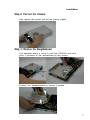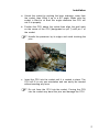
1
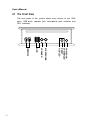
ZPCgx Barebone
User’s Manual
Version 1.0
FB24633000
Federal Communications Commission (FCC) Statement
This equipment has been tested and found to comply with the limits for a Class B digital
device, pursuant to Part 15 of the FCC Rules. These limits are designed to provide
reasonable protection against harmful interference in a residential installation. This
equipment generates, uses, and can radiate radio frequency energy and, if not installed and
used in accordance with the instructions, may cause harmful interference to radio
communications. However, there is no guarantee that interference will not occur in a
particular installation. If this equipment does cause harmful interference to radio or
television reception, which can be determined by turning the equipment off and on, the user
is encouraged to try to correct the interference by one or more of the following measures:
1. Reorient or relocate the receiving antenna.
2. Increase the separation between the equipment and the receiver.
3. Connect the equipment onto an outlet on a circuit different from that to which the
receiver is connected.
4. Consult the dealer or an experienced radio/TV technician for help.
Shielded interconnect cables and shielded AC power cable must be employed with this
equipment to insure compliance with the pertinent RF emission limits governing this
device. Changes or modifications not expressly approved by the system s manufacturer
could void the user s authority to operate the equipment.
Declaration of Conformity
This device complies with part 15 of the FCC rules. Operation is subject to the following
conditions:
1. This device may not cause harmful interference, and
2. This device must accept any interference received, including interference that may cause
undesired operation.
User’s Manual
Disclaimer of Warranties
The information in this document is subject to change without
notice. The manufacturer makes no representatives or
warranties with respect to the contents hereof and specifically
disclaims any implied warranties of merchantability or fitness for
any particular purpose. Furthermore, the manufacturer reserves
the right to revise this publication and to make changes from
time to time in the content hereof without obligation of the
manufacturer to notify any person of such revision or changes.
Copyright
This publication, including all photographs, illustrations and
software, is protected under international copyright laws, with all
rights reserved. Neither this manual, nor any of the material
contained herein, may be reproduced without the express written
consent of the copyright holders.
© 2003. All rights reserved.
Trademark Recognition
Microsoft and Windows are registered trademarks of Microsoft
Corp. Intel and Pentium are registered trademarks of
Intel.
2
Overview
Contents
Electrostatic Precautions................................................. 4
Electrical Precautions.....................................................
5
Safety Precautions.......................................................... 5
Installation Manual..........................................................
Unpacking the System...............................................
Tools.........................................................................
Package Contents......................................................
Chapter 1: Overview....................................................
1.1 The Front View...............................................
1.2 The Rear View................................................
1.3 Positioning the System Unit............................
Chapter 2: Installation.................................................
2.1 Installing Devices............................................
2.2 Getting Started...............................................
Chapter 3: BIOS.........................................................
3.1 Overview.........................................................
3.2 Entering the BIOS Setup Program...................
3.3 Main Menu.....................................................
Chapter 4: Specifications............................................
7
8
8
8
9
10
12
14
15
16
31
33
34
34
35
45
User’s Guide..................................................................
Chapter 1: Basic Care and Tips..................................
Chapter 2: Software Installation...................................
Chapter 3: Positioning the System Unit.......................
Chapter 4: Overview of the System Unit.......................
Chapter 5: Troubleshooting Tips..................................
Chapter 6: Glossary....................................................
1
3
5
9
11
17
21
3
User’s Manual
Electrostatic Precautions
It is quite easy to inadvertently damage your PC, mainboard,
components or devices even before installing them in your
system unit. These devices are sensitive to static electricity
discharge and are normally wrapped in antistatic bags to prevent
this damage. Static electrical discharge can damage computer
components without causing any signs of physical damage. You
must take extra care in handling them to ensure against
electrostatic build-up.
1. Wear an antistatic wrist strap.
2. Do all preparation work on a static-free surface.
3. To prevent electrostatic build-up, leave the device in its antistatic bag until you are ready to install it.
4. If, for any reason, you need to lay down the device first, lay it
on the antistatic bag. Before picking it up again, touch the
antistatic bag and the metal frame of the system chassis at
the same time.
5. Hold the device only by its edges. Be careful not to touch any
of the components, contacts or connections.
6. Avoid touching the pins or contacts on all modules and
connectors. Hold modules or connectors by their ends.
4
Electrostatic discharge (ESD) can damage your CPU,
disk drive and other components. Perform the upgrade
instruction procedures described at an ESD workstation
only. If such a station is not available, you can provide
some ESD protection by wearing an antistatic wrist strap
and attaching it to a metal part of the system chassis. If a
wrist strap is unavailable, establish and maintain contact
with the system chassis throughout any procedures
requiring ESD protection.
Overview
Electrical Precautions
•
Damage to system components and injury to yourself may
result if power is applied during installation. Make sure all
power cables are unplugged before opening the chassis
cover.
•
Before connecting or disconnecting signal cables, make sure
all the power cables of the system unit and all attached
devices are unplugged.
•
When adding or removing devices to or from the system,
make sure the power cables of these devices are unplugged.
For continued protection against risk of electric shock and
fire, use a three-wire grounding plug that will fit into a
grounding-type power outlet. This is a safety measure. Do
not defeat the safety purpose of the grounding-type plug.
Safety Precautions
•
The manufacturer assumes no liability for any damage,
caused directly or indirectly, by improper installation of any
components by unauthorized service personnel. Make sure
operation on this system is conducted by a certified engineer.
•
Read all operating instructions before using the system.
•
Keep operating instructions for future reference.
•
Give special attention to all warnings specified in the manual.
•
Tighten all screws to provide secure connections between
devices and the system.
•
Before using the system, make sure all signal cables and
power cables are correctly connected and are not damaged.
•
To avoid short circuits, keep paper clips, screws and staples
away from connectors and slots.
•
Avoid dust, humidity and temperature extremes.
•
Place the system on a stable surface.
5
User’s Manual
6
•
If an outdoor antenna or cable system is connected to the
product, make sure the antenna or cable system is grounded
to provide protection against voltage surges and built-up
static charges.
•
For added protection during a lightning storm, or when it is
left unattended and unused for long periods of time, unplug it
from the wall outlet, and disconnect the antenna or cable
system. This will prevent damage caused by lightning and
power line surges.
•
An outside antenna system should not be located in the
vicinity of overhead power lines or other light or power
circuits. When installing an outside antenna system, extreme
care should be taken to keep from touching such power lines
or circuits, as contact with them may be fatal.
Overview
Installation Manual
7
User’s Manual
Unpacking the System
Unpack the shipping carton and verify that the contents are all
there and in good condition. Visually inspect the physical condition of the shipping carton. Exterior damage to the shipping
carton may indicate that the contents of the carton are damaged.
If any damage is found, do not remove the system; contact the
dealer where you purchased the system for further instructions.
Tools
•
•
•
Phillips screwdriver
Torx head screwdriver
Antistatic wriststrap
Package Contents
The system unit package includes the following items:
•
•
•
•
•
•
•
ZPC mini P4 barebone
Power adapter
Power cord
CPU cooler and heatsink
Screws
Drivers and software
User’s manual
If any of these items are missing or damaged, please contact
your dealer or sales representative for assistance.
8
Overview
Chapter 1
Overview
9
User’s Manual
1.1 The Front View
The front panel of the system allows easy access to the 1394
ports, USB ports, speaker jack, microphone jack, switches and
LED indicators.
POWER ON
SYSTEM LED
RESET
HDD LED
MICROPHONE
SPEAKER
USB
IEEE1394
10
Overview
Front Component Descriptions
IEEE1394 Ports
These ports allow connecting up to 63 IEEE 1394 devices with
data transfer rates of up to 400Mbps.
USB 2.0 Ports
These ports allow connecting USB devices such as keyboard,
pointing devices, cameras, etc. connected in a series with data
transfer rates up to 480Mb/second.
Speaker Jack
This jack is used to connect external speakers for audio output
from the system. Using this jack disables the line-out jack at the
rear panel.
Microphone Jack
This jack is used to connect an external microphone or output
signals from audio devices. Using this jack disables the mic-in
jack at the rear panel.
System LED
This LED will light when the system’s power is on.
Reset Switch
This switch allows you to reboot without having to power off the
system. It is also used for shutting down the system when
<Ctrl> <Alt> <Del> does not respond.
HDD LED
This LED will light when the hard drive is being accessed.
Power Switch
This switch allows powering on and off the system. Push the
switch once to turn it on and once to turn it off.
11
User’s Manual
1.2 The Rear View
The illustration below shows the components on the rear panel
of the system.
MICROPHONE
USB PORT
SPEAKER
LAN
VGA PORT
PS/2 KEYBOARD
SERIAL PORT
PS/2 MOUSE
POWER CONNECTOR
12
Overview
Rear Component Descriptions
PS/2 Mouse
This port is used to connect a PS/2 mouse.
Serial Port
This port supports serial devices such as serial mouse, PDA
cradle, etc.
LAN Port
This port supports an RJ45 ethernet cable and is used to
connect to a local area network by means of a network hub.
Microphone Jack
This jack is used to connect an external microphone or output
signals from audio devices. Using this jack disables the mic-in
jack at the front panel.
Power Connector
This connector is used to connect a power cord. Power supplied
through this connector supplies power to the system.
PS/2 Keyboard
This port is used to connect a PS/2 keyboard.
VGA Port
This port is used to connect a monitor.
USB Ports
Aside from the 2 USB ports at the front panel, the rear panel is
also equipped with 2 USB ports for connecting additional USB
devices.
Speaker Jack
This jack is used to connect external speakers for audio output
from the system. Using this jack disables the line-out jack at the
front panel.
13
User’s Manual
1.3 Positioning the System Unit
The system unit can be easily positioned in 2 ways. Please refer
to the illustrations below. The arrow indicates the location of the
CPU fan’s air vent. The air vent allows cool air to enter and
warm air to exit the system.
Air Vent
Position 1
(Recommended position)
Air Vent
Position 2
Do not block the air vent or else overheating will occur.
14
Installation
Chapter 2
Installation
15
User’s Manual
2.1 Installing Devices
Most devices will be connected to the I/O ports that are located
at the front panel and rear panel of the system. These ports are
readily accessible that you do not need to remove the rear
panel’s cover. However, if you need to install or replace the CPU,
DIMM, hard drive or CD-ROM drive, you must first remove the
rear panel cover in order to access the sockets and connectors.
The system chassis is designed for easy assembly and
disassembly allowing installation of internal components very
convenient.
Before opening the system unit, make sure you have
done the following.
1. The system and all other peripheral devices
connected to it has been powered-off.
2. Disconnect all power cords and cables.
Step 1: Release the Rear Panel’s Screws
a. Place the system on a flat surface with the rear side facing
you.
b. There are 2 screws that secure the rear panel’s cover to
the chassis. Please release the screws first.
16
Installation
Step 2: Pull out the chassis.
After release the screws, pull out the chassis slightly.
Step 3: Remove the Daughterboard
The daughter board is used to hold the CD-ROM and hard
drive. It connects to the motherboard by two screws.
Remove the daughterboard by pulling it upward.
17
User’s Manual
Step 4: Remove the CPU Cooler
Remove the 4 screws on the cooler by screwdriver.
Step 5: Install the CPU
The surface mount 478-pin CPU socket is exclusively designed
for installing an Intel processor.
If you plan to replace or upgrade the CPU of a system
that has just been powered off, you must let the CPU cool
first before touching it. The CPU may be too hot.
18
Installation
a. Unlock the socket by pushing the lever sideways, away from
the socket, then lifting it up to a 90o angle. Make sure the
socket is lifted to at least this angle otherwise the CPU will
not fit in properly.
b. Position the CPU above the socket then align the gold mark
on the corner of the CPU (designated as pin 1) with pin 1 of
the socket.
Handle the processor by its edges and avoid touching the
pins.
Gold mark
Pin 1
c. Insert the CPU into the socket until it is seated in place. The
CPU will fit in only one orientation and can easily be inserted
without exerting any force.
Do not force the CPU into the socket. Forcing the CPU
into the socket may bend the pins and damage the CPU.
19
User’s Manual
d. Once the processor is in place, push down the lever to lock
the socket. The lever should click on the side tab to indicate
that the CPU is completely secured in the socket.
Step 6: Apply the thermal cream
Apply the thermal cream onto the top of the CPU.
Do not spread the compound all over the surface. When you
place the fan / heat sink on top of the CPU later, the cream
will disperse evenly.
20
Installation
Step 7: Install the CPU Fan / Heat Sink
The CPU must be kept cool by using a CPU fan with heat sink.
Without sufficient air circulation across the CPU and heat sink,
the CPU will overheat damaging both the CPU and motherboard.
Only use the heat sink that boundle with ZPC.
a. Connects the fan's 3-pin power cord to the motherboard.
b. The retention levers at this time are still unlocked. Push the
retention levers down to secure the fan / heat sink.
D
A
C
B
Secure the screws on the heatsink
by cross way.
For example:
Secure the screw A and C, first.
And screw the others B and D.
c. Place the fan / heat sink on top of the CPU. Make sure each
screws fits well to the holes on the motherboard.
21
User’s Manual
Step 8: Install the DDR DIMM
The DIMM socket is for installing a DDR SDRAM system memory
module.
a. Unlock the DIMM socket by pulling the “tabs” that are at the
ends of the socket to the side.
Tab
Tab
b. Position the DIMM above the socket with the “notch” in the
module aligned with the “key” on the socket.
Notch
Key
22
Installation
c. Push down the module into the socket. Make sure it is
completely seated. The tabs will hold the DIMM in place.
23
User’s Manual
Step 9: Install the Hard Disk Drive
The hard disk drive connector is located on the underside of the
daughterboard (the side with 3 connectors for attaching the
daughterboard to the motherboard). Install only a 2.5” hard disk
drive.
a. Align the hard disk drive’s IDE connector to the IDE connector
on the daughterboard.
b. Now slide the HDD in making sure it is secured in place.
24
The system only supports one 2.5” hard disk drive. Make
sure to install the right HDD on the ZPC
Installation
Step 10: Secure the HDD
Secure the HDD on the reverse side
25
User’s Manual
Step 11: Replace the Daughterboard
Align the 3 connectors located on the underside of the
daughterboard (HDD side) to their corresponding connectors on
the motherboard. Gently insert the daughterboard into the
motherboard. Make sure it is firmly seated in place.
Two connectors
near the DIMM
socket
Secure 2 screws each side.
26
One connector
at the edge of
the motherboard.
User’s Manual
Step 12: Install the CD-ROM Drive
The IDE connector for installing the CD-ROM drive is located on
the top side of the daughterboard, opposite the HDD.
a. Secure the CDROM on the daughterboard.
a. Align the CD-ROM drive’s IDE connector to the IDE connector
on the daughterboard.
IDE Connector
27
Installation
c. Use the provided screws to secure the CD-ROM to the CDROM drive’s bracket.
The CD-ROM drive’s eject button is electronic therefore it
requires powering on the system in order to eject the
drive tray.
28
Installation
Step 14: Replace the chassis into the case
a. Before inserting the motherboard back into the chassis,
position the motherboard so that its front side (the side with
CD-ROM) will go first.
b. Align the motherboard to the side rails of the chassis then
slide it in.
29
User’s Manual
Step 15: Secure the chassis to bottom of the case
a. Make sure the holes on the cover match up with the I/O ports.
Step 16: Secure the Screws tight.
30
Installation
2.2 Getting Started
Before you turn on the system, make sure you have completed
the basic system connections. Follow the basic steps below.
1. Connect a monitor.
2. Connect the power cord to an AC outlet.
3. Turn the power on.
Power
button
4. Check the LEDs.
31
User’s Manual
32
BIOS
Chapter 3
BIOS
33
User’s Manual
3.1 Overview
The BIOS is a program that takes care of the basic level of
communication between the CPU and peripherals. In contains
codes for various advanced features found in this motherboard.
The BIOS allows you to configure the system and save the
configuration in a battery-backed CMOS so that the data retains
even when the power is off. In general, the information stored in
the CMOS RAM of the EEPROM will stay unchanged unless a
configuration change has been made such as a hard drive
replaced or a device added.
It is possible that the CMOS battery will fail causing CMOS data
loss. If this happens, you need to install a new CMOS battery
and reconfigure the BIOS settings.
The BIOS is constantly updated to improve the performance of
the motherboard; therefore the BIOS screens in this chapter may
not appear the same as the actual one. These screens are for
reference purposes only.
3.2 Entering the BIOS Setup Program
After you power up the system, the BIOS message appears on
the screen and the memory count begins. After the memory test,
the message “Press DEL to enter setup” will appear on the
screen. If the message disappears before you respond, restart
the system or press the “Reset” button. You may also restart the
system by pressing the <Ctrl> <Alt> and <Del> keys
simultaneously.
Most of the configuration settings are either predefined by the
BIOS Optimized Default settings which are stored with the BIOS
or are automatically detected and configured without requiring
User action. There are a few settings that you may need to
change depending on your system configuration.
34
BIOS
3.3 Main Menu
The main menu displays all the available menu items. To select
the item you want to configure, move the highlight to the menu
item then press <Enter>.
3.3.1 Standard CMOS Features
Standard CMOS Features allows you to configure system
settings such as the current date and time, type of hard disk
drive installed and display type. Memory size is auto-detected by
the BIOS and displayed for your reference.
35
User’s Manual
3.3.2 Advanced BIOS Features
Advanced BIOS Features allows you to configure your system for
basic operation. It mainly configures boot options including boot
devices and their boot order and some power functions. Most
entries are defaults required by the motherboard, while others, if
enabled, will improve the performance of your system or let you
set some features according to your preference.
3.3.3 Advanced Chipset Features
Advanced Chipset Features gives you functions to configure the
system based on the specific features of the chipset. The
chipset manages bus speeds and access to system memory
resources. These items should not be altered unless necessary.
The default settings have been chosen because they provide the
best operating conditions for your system. The only time you
might consider making any changes would be if you discovered
some incompatibility or that data was being lost while using your
system.
36
BIOS
3.3.4 Integrated Peripherals
Integrated Peripherals configures the peripheral features
integrated onto the motherboard. All fields in this screen are set
to optimized default. The IDE transfer mode settings are
autodetected. The system will work with these defaults.
The port settings are standard PC settings. You can disable
onboard devices and change port settings. If you’re going to use
a USB keyboard or mouse, you have to enable support for them
from this screen.
37
User’s Manual
3.3.5 Power Management Setup
Power Management Setup allows you to configure your system
to most effectively save energy. Most of these are overridden by
ACPI power management in Windows. You can select the
Minimum or Maximum configurations rather than the User
Defined defaults; but if you want to customize the settings, select
User Defined mode.
The Soft-Off by PWR-BTTN line controls the function of the
system housing power button. The default sets it to turn the
system on and off when you press the button. The alternate
setting, Delay 4 Sec., requires you to press the power button for
more than four seconds before the system will turn off.
You can also set a date and time for the system to turn on or
wake up using the Resume by Alarm settings.
38
BIOS
3.3.6 PnP/PCI Configurations
PnP/PCI Configurations describes configuring Plug and Play and
other PCI bus settings. It covers some very technical items and it
is strongly recommended that only experienced users should
make any changes to the default settings.
Don’t change the resource settings. They’re set to be handled
automatically by the BIOS. While you can set them manually,
there shouldn’t be any need to do so.
The onboard 1394 and LAN can be configured in this submenu.
39
User’s Manual
3.3.7 PC Health Status
PC Health Status displays detected system information such as
CPU fan speed and various voltage levels.
3.3.8 Smart Setting
Smart Setting configures CPU settings. The default
settings autodetect the CPU and PCI clock settings. The “Spread
Spectrum” setting reduces interference generated by the board
circuitry when Enabled. Don’t change the auto-detected settings
unless you really know what you are doing. You can configure
the CPU settings manually, however, configuring CPU settings at
variance with Intel’s specifications can damage the CPU and
void the CPU warranty.
40
BIOS
3.3.9 Load Fail-Safe Defaults
Load Fail-Safe Defaults loads the troubleshooting default values
permanently stored in the ROM chips. These settings are not
optimal and turn off all high performance features. You should
use these values only if you have hardware problems.
3.3.10 Load Optimized Defaults
Load Optimized Defaults loads optimized settings from the BIOS
ROM. Do this if the configuration record has been corrupted or
mistakenly configured or after the Clear CMOS procedure has
been performed.
41
User’s Manual
3.3.11 Set Supervisor/User Password
These two items set passwords for system access. You can set
a Supervisor or User Password. The password prevents access
to the CMOS Setup Utility (Supervisor) or the entire system
(User). To install a password, follow these steps:
1. Highlight “Set Supervisor Password” or “Set User Password”
in the main menu and press <Enter>.
2. The password dialog box will appear.
3. If you are entering a new password, carefully type in the
password. You cannot use more than eight characters or
numbers. Passwords are case-sensitive. Press <Enter> after
you have typed in the password. If you are deleting a
password that is already installed, just press <Enter> when
the password dialog box appears.
4. The system will ask you to confirm the new password by
asking you to type it in a second time. Carefully type the
password again and press <Enter>, or just press <Enter> if
you are deleting a password that is already installed.
5. If you have used the correct format, the password will be
recorded.
If you decide not to set a password after bringing up the
password entry window, press <Enter>, not <Esc> to exit the
password entry window.
42
BIOS
3.3.12 Save & Exit Setup
This saves the current utility configuration as a new configuration
record, exits the utility and restarts the system using the saved
configuration record. In general, it is not necessary to use the
CMOS Setup Utility once you have fully configured it. In the event
you need to change or re-establish the settings, make sure to
save the settings when you exit the utility or the new settings will
not be stored.
3.3.13 Exit Without Saving
Exits the utility and restarts the system without changing the
saved configuration record.
43
User’s Manual
44
Specifications
Chapter 4
Specifications
45
User’s Manual
4.1 Specifications
Processor
•
•
•
•
•
Supports Intel® Pentium® 4 CPU
533/400MHz system bus
Supports Willamette, Northwood processor
Supports Intel® Celeron processor
Supports Pentium® 4 with MAXIMUM of up to 2.53GHz speed
Memory
•
•
•
•
PC1600/PC2100 DDR SDRAM
DDR266/200 SDRAM
Unbuffered DDR SDRAM
One DDR DIMM socket
Chipset
•
•
•
•
•
•
North bridge: Intel® 845GV
South bridge: ICH4
VIA® 6306 IEEE1394 Host Controller
Realtek® 8100B
Realtek® ALC650
Winbond® Super I/O: W83627HF
Graphics
•
•
•
•
Integrated Intel® Extreme Graphics with 266MHz core speed
Supports Rapid Pixel and Texel Rendering
New technology for drawing 3D scenes - Zone Rendering
Technology
Intel® Dynamic Video Memory Technology
Ethernet
•
•
•
•
•
46
100Mbps and 10Mbps Fast Ethernet operations
Supports 100Mbps and 10Mbps N-way auto-negotiation
Compliant to PCI 2.2 standard and PC99/PC2001 standard
Half/Full duplex capability
Supports Full Duplex Flow Control (IEEE 802.3x)
Specifications
USB 2.0
•
•
•
•
Integrated Hi-Speed USB 2.0
Offer up to 480MB/s, enabling fast data transfers for I/O
peripherals
Two USB 2.0 external ports on the rear panel
Two USB 2.0 external ports on the front panel
Firewire
•
•
•
•
IEEE1394-1394A compliant OHCI compatible programming
interface
Two IEEE1394 ports on the front panel
100/200/400 Mbps data transfer rates
3.3V power supply with 5V tolerant inputs
Available Drive Bay
•
•
One internal drive bay for "slim type" CDROM/DVD driver
One 2.5" drive bay for hard drive disk (Notebook computer
used)
Audio
•
•
•
•
AC'97, Realtek ALC650
18-bit, full duplex AC'97 2.2 compatible stereo audio CODEC
High-performance CODEC with high S/N ratio (>90 dB)
Supports LINE OUT/ MIC IN on rear and front panel
BIOS
•
•
•
•
Award® BIOS
Flash write protection
Auto configuration for IDE hard disk type
Multiple boot options
Power Supply
•
•
Power adapter, 110~240V full range AC input
DC19V output from power adapter
47
User’s Manual
System Management
•
•
•
•
•
Winbond hardware monitor
One 3-pin CPU fan header
One CPU temperature sensor
Monitors seven voltages (Vcore, +1.5V, +2.5V, +3.3V, +5V,
+12V, Battery and 5VSTB)
One 3-pin chassis intrusion header
Certification and Approval
•
•
•
FCC class B
CE mark 89/336/ECC(EMV) and acc. To EU
RU certification from power adapter
Dimension
•
•
•
Height: 263 mm
Width: 184 mm
Depth: 54 mm
Weight
•
•
Net: 2.15 KG (without power adapter and cooler, HDD and
CDROM)
Gross: 2.95 KG (with power adapter, CPU cooler and
CDROM)
Body Color
•
•
48
Silver: supports slot type CDROM
Black: supports tray type CDROM
Basic Care and Tips
User’s Guide
1
User’s Manual
2
Basic Care and Tips
Chapter 1
Basic Care and Tips
3
User’s Manual
1.1 Taking Care of the System Unit
•
Do not expose the system to extreme temperatures.
•
Do not expose the system unit to direct sunlight. Do not
place it near sources of heat such as a radiator.
•
Do not expose the system to rain or moisture.
•
Do not spill water or any liquid on the system.
•
Do not subject the system to magnetic fields.
•
Do not subject the system to heavy shock and vibration.
•
Do not expose the system to dust and dirt.
•
Do not place or drop objects on top of the system to avoid
damaging the system.
•
Do not place the system on uneven surfaces.
1.2 Taking Care of the Power Cord
•
Do not step on the power cord or place heavy objects on top
of it.
•
Do not connect the power cord to any other device.
•
When unplugging the power cord, do not pull on the cord
itself. Pull on the plug.
1.3 Cleaning and Servicing
1. Power off the system and unplug the power cord.
2. Use a soft cloth moistened with water. Do not use liquid or
aerosol cleaners.
4
Software Installation
Chapter 2
Software Installation
5
User’s Manual
2.1 Software Features - Using the Power Installer Disc
This ZPC system comes with driver software and bundled
utility software on the supplied Power Installer CD-ROM disc.
You can run the Power Installer CD-ROM install interface under
Microsoft Windows 9X, NT 4.0, 2000 or XP. The disc's install
interface should load automatically.
2.1.1 Driver Software
This ZPC requires that you install driver software to support
the onboard hardware. You will need to install the following:
1. Intel INF, IAA support software. 2. Audio 3. Graphic 4. LAN
drivers and support software.
6
Software Installation
2.1.2 Utility Software
The Power Installer disc also has several Windows utility
programs on it.
Acrobat Reader
Acrobat Reader allows you to read documents in the Adobe
PDF format, including online documents on the Power Installer disc
Hardware Monitor Utility
Hardware Doctor is a Winbond utility that allows you monitor
the system hardware and obtain information about volatge levels,
internal housing and CPU temperatures.
7
User’s Manual
2.1.4 Installing an OS & Support Software
This section covers installing Operating System software and the
support software on the Power Installer support CD-ROM disc.
Once you have configured the CMOS SetupUtility, you
should install an OS. If you install a supportedMicrosoft OS, you should
also install the driversoftware on the Power Installer disc.
changes to the setup, press <Ctrl> <Alt> <Esc> simultaneously
or <Del> after memory testing is done.
2.2 Operating System
After configuring the BIOS, you must install an operating system
onto your hard drive. Install Windows XP or Windows 2000.
Refer to your operating system’s manual or documentation for
more information.
8
Positioning the System Unit
Chapter 3
Positioning the System Unit
9
User’s Manual
The system unit can be easily positioned in 2 ways. Please refer
to the illustrations below. The arrow indicates the location of the
CPU fan’s air vent. The air vent allows cool air to enter and
warm air to exit the system.
Recommended position
Air Vent
Air Vent
Position 1
Position 2
Do not block the air vent or else overheating will occur.
10
Overview of the System Unit
Chapter 4
Overview of the System Unit
11
User’s Manual
4.1 The Front View
The front panel of the system allows easy access to the 1394
ports, USB ports, speaker jack, microphone jack, switches and
LED indicators.
POWER ON
SYSTEM LED
RESET
HDD LED
MICROPHONE
SPEAKER
USB
IEEE1394
12
Overview of the System Unit
Front Component Descriptions
IEEE 1394 Ports
These ports allow connecting up to 63 IEEE 1394 devices with
data transfer rates of up to 400Mbps.
USB Ports
These ports allow connecting USB devices such as keyboard,
pointing devices, cameras, etc. connected in a series with data
transfer rates up to 480Mb/second.
Speaker Jack
This jack is used to connect external speakers for audio output
from the system. Using this jack disables the line-out jack at the
rear panel.
Microphone Jack
This jack is used to connect an external microphone or output
signals from audio devices. Using this jack disables the mic-in
jack at the rear panel.
System LED
This LED will light when the system’s power is on.
Reset Switch
This switch allows you to reboot without having to power off the
system. It is also used for shutting down the system when
<Ctrl> <Alt> <Del> does not respond.
HDD LED
This LED will light when the hard drive is being accessed.
Power Switch
This switch allows powering on and off the system. Push the
switch once to turn it on and once to turn it off.
13
User’s Manual
4.2 The Rear View
The illustration below shows the components on the rear panel
of the system.
MICROPHONE
USB PORT
SPEAKER
LAN
VGA PORT
PS/2 KEYBOARD
SERIAL PORT
PS/2 MOUSE
POWER CONNECTOR
14
Overview of the System Unit
Rear Component Descriptions
PS/2 Mouse
This port is used to connect a PS/2 mouse.
Serial Port
This port supports serial devices such as serial mouse, PDA
cradle, etc.
LAN Port
This port supports an RJ45 ethernet cable and is used to
connect to a local area network by means of a network hub.
Microphone Jack
This jack is used to connect an external microphone or output
signals from audio devices. Using this jack disables the mic-in
jack at the front panel.
Power Connector
This connector is used to connect a power cord. Power supplied
through this connector supplies power to the system.
PS/2 Keyboard
This port is used to connect a PS/2 keyboard.
VGA Port
This port is used to connect a monitor.
USB Ports
Aside from the 2 USB ports at the front panel, the rear panel is
also equipped with 2 USB ports for connecting additional USB
devices.
Speaker Jack
This jack is used to connect external speakers for audio output
from the system. Using this jack disables the line-out jack at the
front panel.
15
User’s Manual
16
Introduction
1
Chapter 5
Troubleshooting Tips
17
User’s Manual
This chapter instructs you on how to deal with common system
problems. Read it before calling a technician for service.
Solutions to more serious problems require opening up the
system. If you do not know how to deal with the problem, we
advise that you contact your dealer or an authorized service
center for assistance.
The following is a list of the most common things to check when
you encounter problems.
1. Make sure the power switch of the system and each
peripheral device is turned on.
2. Make sure all cables and power cords are tightly connected.
3. Make sure the electrical outlet to which your peripheral
devices are connected is working. Test the outlet by plugging
in a lamp or other electrical device.
4. Make sure the monitor is turned on.
5. Make sure the display’s brightness and contrast controls are
adjusted properly.
When the computer is turned on, nothing happens.
Make sure one end of the AC power cord is plugged into a live
outlet and the other end properly plugged into the back of the
system.
The display screen remains dark after the system is turned
on.
1. Make sure that the monitor’s power switch is on.
2. Make sure one end of the monitor’s power cord is properly
attached to the monitor and the other end is plugged into a
working AC outlet. If necessary, try another outlet.
3. Adjust the brightness of the display by turning the monitor’s
brightness control knob.
18
Troubleshooting Tips
The picture seems to be constantly moving.
1. The monitor has lost its vertical sync. Adjust the monitor’s
vertical sync.
2. Move away any objects, such as another monitor or fan, that
may be creating a magnetic field around the display.
The screen seems to be constantly wavering.
If the monitor is close to another monitor, the adjacent monitor
may need to be turned off. Fluorescent lights adjacent to the
monitor may also cause screen wavering.
The hard disk drive failed.
Make sure the correct drive type has been entered in the BIOS.
The disk drive takes excessively long formatting period.
If your hard drive takes an excessively long period of time to
format, it is likely a cable connection problem. However, if your
hard drive has a large capacity, it will take a longer time to
format.
The serial device is not working.
1. Make sure that the serial device’s power (if there is one) is
turned on and that the device is on-line.
2. Verify that the device is properly plugged into the serial port
on the rear of the system.
3. Verify that the attached serial device works by attaching it to a
serial port that is working and configured correctly. If the
serial device does not work, either the cable or the serial
device has a problem. If the serial device works, the problem
may be due to the onboard I/O or the address setting.
4. Make sure the COM settings and I/O address are configured
correctly.
19
User’s Manual
20
Glossary
Chapter 6
Glossary
21
User’s Manual
IEEE 1394
IEEE 1394 is fully compliant with the 1394 OHCI (Open Host
Controller Interface) 1.1 specification. It supports up to 63
devices that can run simultaneously on a system. 1394 is a fast
external bus standard that supports data transfer rates of up to
400Mbps. In addition to its high speed, it also supports
isochronous data transfer which is ideal for video devices that
need to transfer high levels of data in real-time. 1394 supports
both Plug-and-Play and hot plugging.
BIOS (Basic Input/Output System)
The BIOS is the set of essential software routines that tests
hardware at startup, starts the operating system, and supports
the transfer of data among hardware devices. The BIOS is
stored in read-only memory (ROM) so that it can be executed
when the computer is turned on. BIOS parameters can be
configured by the user through the BIOS setup program.
CPU (Central Processing Unit)
CPU, also referred to as “Processor”, functions as the brain of
the computer. It is the device that interprets and executes
instructions and processes all the data stored in memory.
DDR (Double Data Rate)
A type of SDRAM that doubles the data rate through reading and
writing at both the rising and falling edge of each clock. This
effectively doubles the speed of operation therefore doubling the
speed of data transfer.
DIMM (Dual Inline Memory Module)
A type of memory board composed of RAM chips mounted on a
circuit board. DIMMs are characterized by a 64-bit data path and
pins (connectors) on each side that are on different circuits and
that respond to different signals.
IDE (Integrated Device Electronics)
A type of disk-drive interface in which the controller electronics
reside on the drive itself, eliminating the need for a separate
adapter card.
22
Glossary
North Bridge
The CPU to PCI interface. It also contains the memory and
cache controllers.
PS/2 Port
The PS/2 ports are based on IBM’s Micro Channel Architecture.
The Micro Channel functions as either a 16-bit or a 32-bit bus.
Serial Port
An input/output channel that sends and receives data to and
from a computer’s CPU or a communication device one bit at a
time. The serial port is used as an interface with some
peripheral devices such as mouse, modems, etc.
Ultra DMA/100
Ultra DMA is based on direct memory access. It improves ATA/
IDE performance, doubles burst transfer rates to 100 megabytes
per second and increases data transfer integrity.
USB 2.0 (Universal Serial Bus)
A serial bus with a data transfer rate of 480Mb/second for the
system that supports USB 2.0 specification. USB can connect up
to 127 peripherals such as external CD-ROM drives, keyboards,
mice, etc. It has the ability to automatically add and configure
new devices without having to shut down and restart the system
(hot plugging).
23