1
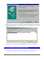
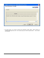
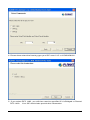
USB ADSL Modem
ADU-2120
User’s Manual
Copyright
Copyright (C) 2004 PLANET Technology Corp. All rights reserved.
The products and programs described in this User’s Manual are licensed products of
PLANET Technology, This User’s Manual contains proprietary information protected by
copyright, and this User’s Manual and all accompanying hardware, software, and documentation are copyrighted.
No part of this User’s Manual may be copied, photocopied, reproduced, translated, or reduced to any electronic medium or machine-readable form by any means by electronic or
mechanical. Including photocopying, recording, or information storage and retrieval systems,
for any purpose other than the purchaser's personal use, and without the prior express written permission of PLANET Technology.
Disclaimer
PLANET Technology does not warrant that the hardware will work properly in all environments and applications, and makes no warranty and representation, either implied or expressed, with respect to the quality, performance, merchantability, or fitness for a particular
purpose.
PLANET has made every effort to ensure that this User’s Manual is accurate; PLANET disclaims liability for any inaccuracies or omissions that may have occurred.
Information in this User’s Manual is subject to change without notice and does not represent
a commitment on the part of PLANET. PLANET assumes no responsibility for any inaccuracies that may be contained in this User ’s Manual. PLANET makes no commitment to update
or keep current the information in this User ’s Manual, and reserves the right to make improvements to this User’s Manual and/or to the products described in this User’s Manual, at
any time without notice.
If you find information in this manual that is incorrect, misleading, or incomplete, we would
appreciate your comments and suggestions.
FCC Compliance Statement
This equipment generates and uses radio frequency energy and if not installed and used
properly, that is, in strict accordance with the instructions provided with the equipment, may
cause interference to radio and TV communication. The equipment has been tested and
found to comply with the limits for a Class A computing device in accordance with the specifications in Subpart B of Part 15 of FCC rules, which are designed to provide reasonable
protection against such interference in a residential installation. However, there is no guarantee that interference will not occur in a particular installation. If you suspect this equipment
is causing interference, turn your Ethernet Switch on and off while your radio or TV is showing interference, if the interference disappears when you turn your Ethernet Switch off and
reappears when you turn it back on, there is interference being caused by the Ethernet
Switch.
You can try to correct the interference by one or more of the following measures:
w Reorient the receiving radio or TV antenna where this may be done safely.
w To the extent possible, relocate the radio, TV or other receiver away from the Switch.
w Plug the Ethernet Switch into a different power outlet so that the Switch and the receiver
are on different branch circuits.
If necessary, you should consult the place of purchase or an experienced radio/television
technician for additional suggestions.
CE mark Warning
The is a class B device, In a domestic environment, this product may cause radio interference, in which case the user may be required to take adequate measures.
Trademarks
The PLANET logo is a trademark of PLANET Technology. This documentation may refer to
numerous hardware and software products by their trade names. In most, if not all cases,
these designations are claimed as trademarks or registered trademarks by their respective
companies.
Revision
User’s Manual for PLANET USB ADSL Modem
Model: ADU-2120A / ADU-2120B
Rev: 1.0 (JAN. 2004)
Part No.: EM-ADU2120
TABLE OF CONTENTS
CHAPTER 1 INTRODUCTION ................................................................................. 1
FEATURES .............................................................................................................. 1
DATA REQUIREMENT................................................................................................ 1
ADSLRFC1483 mode user............................................................................... 1
ADSL PPPoE/PPPoA mode user ..................................................................... 1
SYSTEM REQUIREMENT ........................................................................................... 2
LED DEFINITION...................................................................................................... 2
CHAPTER 2 INSTALLATION................................................................................... 3
HARDWARE INSTALLATION........................................................................................ 3
DRIVER INSTALLATION WITH W INDOWS 98 ................................................................ 3
DRIVER INSTALLATION WITH W INDOWS ME............................................................... 5
DRIVER INSTALLATION WITH W INDOWS 2000 ............................................................ 6
DRIVER INSTALLATION WITH W INDOWS XP ............................................................... 9
DRIVER CONFIGURATION ....................................................................................... 11
CHAPTER 3 PPPOE AND PPPOA CONFIGURATION......................................... 15
ADSL LAN CONFIGURATION ................................................................................. 16
CHAPTER 4. USER INTERFACE .......................................................................... 17
ACCESSING CSA .............................................................................................. 17
CSA USER SCREEN.......................................................................................... 17
CHAPTER 5. UNINSTALL MODEM....................................................................... 20
USB MODEM UNINSTALLATION ............................................................................... 20
CHAPTER 6. TROUBLESHOOTING ..................................................................... 21
CHAPTER 7. ABBREVIATIONS ............................................................................ 22
Chapter 1
Introduction
1
PLANET USB ADSL modem ADU-2120 is designed to provide cost-effective access to high-speed ADSL services. With our ADSL modem, surfing on Internet is
just like driving a sport car on the Express Highway. Video on Demand, Videoconference and any high-speed Internet applications is not a dream any more. But a
reality!
Features
l
l
l
l
l
l
l
USB bus-powered; an external power supply is not required
ANSI T1.413 issue 2, ITU G.dmt(G.992.1), and ITU G.lite(G.992.2) compliant
Software upgradeable
Support the following three modes
n
PPP over ATM LLC or VCMUX (RFC 2364)
n
PPP over Ethernet LLC or VCMUX (RFC 2516)
n
RFC 1483 LLCSNAP/VC-MUX
Bridged IP over ATM, LLC or VCMUX (RFC 1483)
Routed IP over ATM LLC or VCMUX (RFC 1483)
Supports DSL downstream data rates up to 8 Mbps
Supports DSL upstream data rates up to 1 Mbps
Compliant with Universal Serial Bus Specification Revision 1.1
Data Requirement
You must get the following data information from your ISP or phone company to set
up ADU-2120.
ADSLRFC1483 mode user
l
l
l
l
VPI/VCI value
Encapsulation mode(example: RFC 1483...etc.)
IP Address, Subnet Mask
Gateway, DNS related information
ADSL PPPoE/PPPoA mode user
l
l
l
VPI/VCI value
Encapsulation mode (example: RFC 2364, 2516...etc.)
Username and password for authentication
1
System Requirement
l
l
l
l
Mainboard with USB support
Pentium II CPU and above or compatible
RAM: 64M or above
Windows 98SE, Windows 2000, Windows ME, Windows XP, Windows 2003
Server
NOTE: For Windows XP it is recommended that your PC have at least 128 M Bytes of memory.
LED definition
Below is the front panel of ADU-2120 and its LEDs definition.
LED
USB – Red
USB – Green
ADSL – Red
ADSL - Green
Definition
Flashing when is attaching and configuring
Solid green when the connection to PC is OK and the driver
is well installed.
Flashing when the software downloading from PC is successful.
Flashing when is trying to connect to ADSL DSLAM
Solid green when is ready for dial-up connection
2
Chapter 2
Installation
2
Please refer to the following steps to complete ADU-2120 installation.
Hardware Installation
1. Turn on your PC
2. Insert the rectangular end of a USB cable into the USB port of your PC. Then,
insert the square end of the USB cable into the USB port of the ADU 2120.
3. PC will automatically detect this modem as “DynaMiTe USB Modem”.
4. Insert bundled USB driver CD into the proper drive and follow instruction to install ADU 2120.
Driver Installation with Windows 98
1. The “Add New Hardware Wizard” will be displayed. Click Next.
2. Choose the “search for a better Driver (Recommended)” and click Next.
3
3. Choose “Specify a location”. Then click “Browse” to find out the driver location
to install. (Assume "E" is your CD-ROM drive, the driver can be found in
E:\driver\ADU-2120B) then click OK. Please then click “Next” to continue.
4
4. The Add New Hardware Wizard will appear and indicate the PLANET
ADU-2120 USB ADSL modem has been recognized and will install a new
driver. Click Next
5. Please then go to Section “Driver Configuration” for further configuration.
Driver Installation with Windows ME
1. The “Found New Hardware Wizard” will be displayed. Insert ADU-2120 driver
CD and click Next.
5
2. Please specify the path which ADSL modem connected your computer to
Internet, then click OK. Please select the directory with ADU-2120 driver and
then click “OK”.
3. Please then go to Section “Driver Configuration” for further configuration.
Driver Installation with Windows 2000
1. The “Add New Hardware Wizard” will be displayed.
Please click Next.
6
2. Choose the “Search for a suitable driver for my device (recommended)”, and
click Next.
3. Next you will be prompted for software drivers. Select Specify a location.
7
4. Insert the ADSL Driver CD into your systems CD-ROM drive and then click
“Browse” to find out the driver location to install. (Assume "E" is your CD-ROM
drive, the driver can be found in E:\driver\ADU-2120B) then click OK.
5. The Found New Hardware Wizard will then find the ADSL USB MODEM, click
Next.
8
6. The “Digital Signature Not Found” window will pop-up, Click Yes.
7. Please then go to Section “Driver Configuration” for further configuration.
Driver Installation with Windows XP
1. The “Add New Hardware Wizard” will be displayed. Choose Install from a list or
specific location (Advanced) and click Next.
9
2. Insert the ADSL Driver CD into your systems CD-ROM drive, select “Include
this location in the search” and then click “Browse” to find out the driver location to install. (Assume "E" is your CD-ROM drive, the driver can be found in
E:\driver\ADU-2120B). Click “Next” to continue.
10
3. The Hardware Installation window appears. Click Continue Anyway.
4. Now please go to Step 3 for driver configuration.
Driver Configuration
Step 3: Driver Configuration
1. The system will start to copy the driver and utility files to your PC. After completing, the ADSL Modem Driver Suite installation page is shown. Click “Next”
to continue.
2. The modem driver version is shown.
Click “Next” to continue.
11
3. On this page, you need to select the operation mode (RFC 1483, PPPoA or
PPPoE) and input the VPI / VCI values per your ISP’s requirement. Click “Next”
to continue.
12
4. Please then select the framing type your ISP uses: LLC or VCMUX/NULL.
5. If you select RFC 1483, you will then need to specified if it is Bridged or Routed
RFC 1483. Your ISP should also provide this information.
13
6. The system will then ask you to reboot your PC. Please select “Yes, I want to
restart my computer now” and click OK to finish this setup procedure.
7. After reboot, the system will ask you to install the driver again.
“Install the software automatically“ and click “Next” to continue.
Please select
14
3
8. The Hardware Installation page is shown.
Windows XP and “OK” on Windows 2000
Please select “Continue Anyway” or
3. The Found New Hardware Wizard window appears and displays your newly installed PLANET ADU-2120 USB ADSL Interface, then click Finish. The system
may ask you to reboot again. Please select “Yes” to reboot if asked.
Chapter 3
PPPoE and PPPoA Configuration
15
ADSL LAN Configuration
To configure the connection, after you have installed the appropriate
driver:
4
Step 1. Click either the desktop icon, or the Dial-Up Networking icon to open the
Connect To window. For Windows XP, please click “Start” -> “Settings” -> “Network Connections” and then click the ADSL or PPPoE on the “Dial-up” option.
Step 2. Provide the following information
Step a. Supply the User Name.
Step b. Supply the Password.
Step c. Click the field for Save Password, if you want the system to remember
the password.
Step d. Click DIAL to set up the connection.
NOTE: The data for the Phone number field has been furnished by your
service provider.
Note: There is a known issue for PPPoA in case of Windows 98 Second Edition
and Windows Millennium. Extra disabled adapters may appear in Device Manager.
These extra adapters do not affect the functionality of the enabled adapter. However, do not remove the disabled adapters.
Check this link for more information .http://support.microsoft.com/default.aspx?scid=kb;EN-US;q279116
16
Chapter 4.
User Interface
ACCESSING CSA
The User Interface to the ADSL Modem is provided by the Control and Status
Application (CSA). You can access the CSA by double-clicking on the CSA icon
in the System Tray, located near the clock on the task bar. The icon, which appears as two monitor screens, also changes color to indicate the status of the modem (see Table 1. ICON Condition.).
If the icon does not appear in the System Tray, it can be restored by any of the following methods:
• Restart the PC.
• Click the Windows START button, then Programs, ADSL Modem Driver, and
Add CSA Tray Icon.
• Go to the CONTROL PANEL and double-click the ADSL Control and Status
icon.
While connected, the System Tray CSA icon provides pop-up text that gives information about the current ADSL connection. This text appears when the cursor is
placed over the icon. The information displayed is:
• bytes transmitted
• bytes received
• connection rate.
Table 1. ICON Condition
Color
Condition
Black
The modem is not available.
Red
The modem is disconnected.
Blue
The modem is waiting for initialization.
Yellow
The modem is initializing.
Green
The modem is connected and functioning.
CSA USER SCREEN
17
Modem Performance
The Modem Performance displays performance information. The primary purpose
is to display the instantaneous throughput rate for both transmit and receive paths
of the modem. This rate is calculated based on the poll period (generally 2 seconds)
and the number of bytes passed during that time.
Transmit and Receive
The throughput is indicated through two bar graphs, each provides a maximum rate
label indicating the transmit and receive bit rates currently in use. The bar graph
displays peak throughput rates over the last 10-second period. Basically, the user
interface records the instantaneous throughput for each poll period over the last 10
seconds, and the peak rate is displayed as the maximum value achieved over that
10-second period. This value is indicated on the throughput graph with a vertical
red marker indicating the peak rate.
The user interface displays operational information about the ADSL modem, relevant when the modem is connected. When the modem is not connected, all of the
non-averaged operational information are reported as zero unless otherwise CSA
User Screen Connection Status noted. This means that when the modem is disconnected, these values should immediately report zero.
Connection Status
The Connection Status field changes to indicate the status of the modem connec18
tion:
• ADSL link connected
• ADSL link disconnected
Device Status
The Device Status field changes to indicate the status of the modem connection:
• ADSL Modem available
• ADSL Modem not available
Connect/ Disconnect Button
The CONNECT/DISCONNECT button performs the connection/disconnection operation. If the ADSL Modem is unavailable, the button is disabled. This occurs
when the ADSL modem driver is disabled or fails to communicate correctly.
Close Button
The CLOSE button closes the main interface screen. If the main window was displayed while the system tray icon was present, then the application continues to
execute - hiding the main screen. If for some reason the icon is not present, however, the application is terminated.
Help
On-line help is available through the HELP screens. Press the F1 key at the CSA
main screen to see the Help table of contents. This is available from the context
menus and system tray icon menus Help selection.
AboutCSA
The ABOUTCSA button displays the product information, including the version
number and date.
19
Chapter 5.
Uninstall Modem
5
USB Modem uninstallation
USB MODEM
To uninstall the software and hardware for the USB ASDL Modem, perform the
following:
Step 1. Detach the USB Modem from your computer.
Step 2. At Windows Start, click on Programs > ADSL Modem Driver > Remove
ADSL Modem Driver.
Step 3. A Question screen asks for verification of an uninstallation. Click YES to
continue.
Step 4. At the Rebooting Machine screen, click the radio button for Yes, I want to
restart my computer now, and then click OK to complete the uninstallation. The
system is restarted.
You have successfully uninstalled the software and hardware for the modem.
20
Chapter 6.
Troubleshooting
6
If your internet connection is not working, the following hints may be helpful. After
trying these hints, if you still can not make your connection work, it is recommended that you ask your service provider for assistance. To run troubleshooting
on the system:
Step 1. Is the system tray CSA icon green? If it is not, try a restart of your PC. This
may clear the problem.
Step 2. If this does not correct the problem, make the following checks:
Step a. Is your phone line connected to the wall outlet and to your modem?
Step b. For USB. Is the modem connected to the USB port?
Step 3. If the CSA icon color does not show green after performing the steps
above, it is recommended to "cleanup" the installation and reinstall. "Cleanup" is a
utility that can be run from the Installation CD. At the Windows Start button, select
Run, click Browse and search for "Cleanup.exe" on the installation CD. Once you
Run the utility, it pops up a message for restarting the system. Re-install the modem after a restart.
Step 4. If the CSA tray icon is still not showing green uninstall the modem (see
“Chapter 5. Uninstall Modem”) and re-install.
Step 5. If the system tray CSA icon is green, but you have problems in logging in,
or connecting to, your ISP, running "Cleanup’ and reinstalling may solve the problem (see "Step 3" for details).
Step 6. If still experiencing difficulties, contact your service provided for help.
21
Chapter 7.
Abbreviations
AAL
7
ATM Adaptation Layer. A function performed during ATM cell processing to
adapt traditional IP or Ethernet traffic for transmission through an ATM
network.
ADSL Asymmetric Digital Subscriber Line. A method for modulating data to
achieve high bit rates over common twisted-pair copper wire.
ATM
Asynchronous Transfer Mode. A method of networking the uses a fixed
length cell to transmit data (versus a variable length packet). The fixed
length cell improved cell switch performance, hence improves end-to-end
data transfer performance.
CBR
Constant Bit Rate. This class of service delivers ATM traffic at a consistent
rate. The rate is specified during virtual circuit construction and cannot exceed the specified value.
CSA
Control and Status Application. Basis for this whole document. GUI
Graphical User Interface. The Windows-based interface a user interacts
with to manage and monitor the ADSL modem activity.
LEC
Local Exchange Carrier. The business party responsible for delivery of
telephone service to a geographic region.
PDU
Protocol Data Unit. Similar to a data packet, a protocol data unit is simply a
data packet that has some protocol processing applied to it.
PVC
Permanent Virtual Circuit. A virtual circuit that is defined and exists until
explicitly destroyed.
SAR
Segmentation and Reassembly. The process of segmenting AAL PDUs
into cells and reassembling received cells as AAL PDUs.
SVC
Switched Virtual Circuit. A virtual circuit that is dynamically created and
destroyed using UNI signaling.
UBR
Unspecified Bit Rate. This class of service attempts to deliver ATM traffic in
a ‘best effort’ mode, as long as the amount of bandwidth consumed by the
effort does not exceed a specified peak rate.
UNI
User-To-Network Interface. The interface between the user endpoint
equipment and the first ATM switch encountered in the network. The UNI
specification suite (versions 3.0, 3.1, and 4.0) is maintained by the ATM
Forum.
VBR
Variable Bit Rate. Service class attempts to deliver ATM traffic.
VC
Virtual Circuit. A data path setup across an ATM link.
VCI
Virtual Circuit Identifier. A 16-bit value that is included in an ATM cell
header to identify the destination virtual circuit.
VPI
Virtual Path Identifier. An 8-bit value that is included in an ATM cell header
to identify the destination virtual path.
22